EP2407565A1 - A method of improving the mechanical properties of a component - Google Patents
A method of improving the mechanical properties of a component Download PDFInfo
- Publication number
- EP2407565A1 EP2407565A1 EP11170184A EP11170184A EP2407565A1 EP 2407565 A1 EP2407565 A1 EP 2407565A1 EP 11170184 A EP11170184 A EP 11170184A EP 11170184 A EP11170184 A EP 11170184A EP 2407565 A1 EP2407565 A1 EP 2407565A1
- Authority
- EP
- European Patent Office
- Prior art keywords
- forging
- heat treatment
- shaped preform
- predetermined temperature
- strain
- Prior art date
- Legal status (The legal status is an assumption and is not a legal conclusion. Google has not performed a legal analysis and makes no representation as to the accuracy of the status listed.)
- Granted
Links
Images







Classifications
-
- C—CHEMISTRY; METALLURGY
- C22—METALLURGY; FERROUS OR NON-FERROUS ALLOYS; TREATMENT OF ALLOYS OR NON-FERROUS METALS
- C22F—CHANGING THE PHYSICAL STRUCTURE OF NON-FERROUS METALS AND NON-FERROUS ALLOYS
- C22F1/00—Changing the physical structure of non-ferrous metals or alloys by heat treatment or by hot or cold working
- C22F1/10—Changing the physical structure of non-ferrous metals or alloys by heat treatment or by hot or cold working of nickel or cobalt or alloys based thereon
-
- C—CHEMISTRY; METALLURGY
- C22—METALLURGY; FERROUS OR NON-FERROUS ALLOYS; TREATMENT OF ALLOYS OR NON-FERROUS METALS
- C22C—ALLOYS
- C22C1/00—Making non-ferrous alloys
- C22C1/02—Making non-ferrous alloys by melting
- C22C1/023—Alloys based on nickel
-
- C—CHEMISTRY; METALLURGY
- C22—METALLURGY; FERROUS OR NON-FERROUS ALLOYS; TREATMENT OF ALLOYS OR NON-FERROUS METALS
- C22C—ALLOYS
- C22C14/00—Alloys based on titanium
-
- C—CHEMISTRY; METALLURGY
- C22—METALLURGY; FERROUS OR NON-FERROUS ALLOYS; TREATMENT OF ALLOYS OR NON-FERROUS METALS
- C22C—ALLOYS
- C22C19/00—Alloys based on nickel or cobalt
- C22C19/03—Alloys based on nickel or cobalt based on nickel
-
- C—CHEMISTRY; METALLURGY
- C22—METALLURGY; FERROUS OR NON-FERROUS ALLOYS; TREATMENT OF ALLOYS OR NON-FERROUS METALS
- C22C—ALLOYS
- C22C19/00—Alloys based on nickel or cobalt
- C22C19/03—Alloys based on nickel or cobalt based on nickel
- C22C19/05—Alloys based on nickel or cobalt based on nickel with chromium
-
- C—CHEMISTRY; METALLURGY
- C22—METALLURGY; FERROUS OR NON-FERROUS ALLOYS; TREATMENT OF ALLOYS OR NON-FERROUS METALS
- C22C—ALLOYS
- C22C19/00—Alloys based on nickel or cobalt
- C22C19/03—Alloys based on nickel or cobalt based on nickel
- C22C19/05—Alloys based on nickel or cobalt based on nickel with chromium
- C22C19/051—Alloys based on nickel or cobalt based on nickel with chromium and Mo or W
-
- C—CHEMISTRY; METALLURGY
- C22—METALLURGY; FERROUS OR NON-FERROUS ALLOYS; TREATMENT OF ALLOYS OR NON-FERROUS METALS
- C22C—ALLOYS
- C22C19/00—Alloys based on nickel or cobalt
- C22C19/03—Alloys based on nickel or cobalt based on nickel
- C22C19/05—Alloys based on nickel or cobalt based on nickel with chromium
- C22C19/051—Alloys based on nickel or cobalt based on nickel with chromium and Mo or W
- C22C19/056—Alloys based on nickel or cobalt based on nickel with chromium and Mo or W with the maximum Cr content being at least 10% but less than 20%
-
- C—CHEMISTRY; METALLURGY
- C22—METALLURGY; FERROUS OR NON-FERROUS ALLOYS; TREATMENT OF ALLOYS OR NON-FERROUS METALS
- C22C—ALLOYS
- C22C19/00—Alloys based on nickel or cobalt
- C22C19/03—Alloys based on nickel or cobalt based on nickel
- C22C19/05—Alloys based on nickel or cobalt based on nickel with chromium
- C22C19/051—Alloys based on nickel or cobalt based on nickel with chromium and Mo or W
- C22C19/057—Alloys based on nickel or cobalt based on nickel with chromium and Mo or W with the maximum Cr content being less 10%
-
- C—CHEMISTRY; METALLURGY
- C22—METALLURGY; FERROUS OR NON-FERROUS ALLOYS; TREATMENT OF ALLOYS OR NON-FERROUS METALS
- C22F—CHANGING THE PHYSICAL STRUCTURE OF NON-FERROUS METALS AND NON-FERROUS ALLOYS
- C22F1/00—Changing the physical structure of non-ferrous metals or alloys by heat treatment or by hot or cold working
- C22F1/16—Changing the physical structure of non-ferrous metals or alloys by heat treatment or by hot or cold working of other metals or alloys based thereon
- C22F1/18—High-melting or refractory metals or alloys based thereon
- C22F1/183—High-melting or refractory metals or alloys based thereon of titanium or alloys based thereon
-
- F—MECHANICAL ENGINEERING; LIGHTING; HEATING; WEAPONS; BLASTING
- F01—MACHINES OR ENGINES IN GENERAL; ENGINE PLANTS IN GENERAL; STEAM ENGINES
- F01D—NON-POSITIVE DISPLACEMENT MACHINES OR ENGINES, e.g. STEAM TURBINES
- F01D5/00—Blades; Blade-carrying members; Heating, heat-insulating, cooling or antivibration means on the blades or the members
- F01D5/02—Blade-carrying members, e.g. rotors
-
- F—MECHANICAL ENGINEERING; LIGHTING; HEATING; WEAPONS; BLASTING
- F05—INDEXING SCHEMES RELATING TO ENGINES OR PUMPS IN VARIOUS SUBCLASSES OF CLASSES F01-F04
- F05D—INDEXING SCHEME FOR ASPECTS RELATING TO NON-POSITIVE-DISPLACEMENT MACHINES OR ENGINES, GAS-TURBINES OR JET-PROPULSION PLANTS
- F05D2230/00—Manufacture
- F05D2230/10—Manufacture by removing material
-
- F—MECHANICAL ENGINEERING; LIGHTING; HEATING; WEAPONS; BLASTING
- F05—INDEXING SCHEMES RELATING TO ENGINES OR PUMPS IN VARIOUS SUBCLASSES OF CLASSES F01-F04
- F05D—INDEXING SCHEME FOR ASPECTS RELATING TO NON-POSITIVE-DISPLACEMENT MACHINES OR ENGINES, GAS-TURBINES OR JET-PROPULSION PLANTS
- F05D2230/00—Manufacture
- F05D2230/20—Manufacture essentially without removing material
- F05D2230/25—Manufacture essentially without removing material by forging
-
- F—MECHANICAL ENGINEERING; LIGHTING; HEATING; WEAPONS; BLASTING
- F05—INDEXING SCHEMES RELATING TO ENGINES OR PUMPS IN VARIOUS SUBCLASSES OF CLASSES F01-F04
- F05D—INDEXING SCHEME FOR ASPECTS RELATING TO NON-POSITIVE-DISPLACEMENT MACHINES OR ENGINES, GAS-TURBINES OR JET-PROPULSION PLANTS
- F05D2230/00—Manufacture
- F05D2230/40—Heat treatment
Definitions
- the present invention relates to a method of improving the mechanical properties of a component, in particular to a method of improving the mechanical properties of a forged nickel base superalloy article, e.g. a forged nickel base superalloy gas turbine engine turbine disc or a forged nickel base superalloy gas turbine engine compressor disc.
- a forged nickel base superalloy article e.g. a forged nickel base superalloy gas turbine engine turbine disc or a forged nickel base superalloy gas turbine engine compressor disc.
- High strength nickel base superalloys for critical rotor components are made by complex powder processing route.
- Other high strength nickel base superalloys for critical rotor components are made by a cast and wrought route.
- the complex powder processing route comprises vacuum induction melting (VIM) of the nickel base superalloy, inert gas, e.g. argon, atomisation (IGA) to produce a metal powder, sieving of the metal powder, blending of the metal powder, canning of the metal powder, hot isostatic pressing (HIP) of the metal powder, extrusion to form a billet, isothermal forging of the billet to form a forging, solution heat treatment (SHT) of the forging, ageing heat treatment (AHT) of the forging and machining the forging to form the final shape of a component.
- the cast and wrought route comprises vacuum induction melting (VIM), electro slag refining (ESR), vacuum arc remelting (VAR), conversion of the ingot to a billet through multiple upset and heat treatment operations, isothermal forging of the billet to a forging, solution heat treatment (SHT) of the forging, ageing heat treatment (AHT) of the forging and machining the forging to form the final shape of a component.
- VIP vacuum induction melting
- ESR electro slag refining
- VAR vacuum arc remelting
- Lower strength and/or lower temperature capability nickel base superalloys such as Waspaloy or IN718, forgings are formed to shape using conventional forging, e.g. press forging.
- the forgings undergo a complex heat treatment cycle to optimise the grain size and the strengthening precipitate phase distribution.
- the forging is then machined to the final shape of a component.
- nickel base superalloys are optimised to provide maximum creep and fatigue crack growth properties and/or maximum tensile and fatigue properties by altering the grain size of the nickel base superalloy and the volume fraction and size of strengthening precipitates, which results in a trade off in mechanical properties. Therefore, it is desirable to increase the creep properties and/or tensile properties of a high strength nickel base superalloy without altering the grain size of the nickel base superalloy or the size and/or distribution of other strengthening phases in the nickel base superalloy.
- the residual stresses in the disc are added to the stresses induced in the disc by the operation of the gas turbine engine. This combined stress must be maintained below the stress level that would be predicted to cause tensile or fatigue failure of the turbine disc or compressor disc. Thus, the residual stress in the turbine disc, or compressor disc, limits the mechanical stress cycle that the engine is designed for.
- the present invention seeks to provide a novel method of manufacturing a component which reduces, preferably overcomes, the above mentioned problem or problems.
- the present invention provides a method of improving the mechanical properties of a component comprising the steps of:-
- Step f) may be after step c) and before step d), step f) may be after step d) and before step e) or step f) may be concurrent with step d).
- the second predetermined temperature is between 700°C and 870°C.
- the second predetermined temperature is between 750°C and 850°C. More preferably the second predetermined temperature is between 760°C and 810°C. The second predetermined temperature may be 760°C, 802°C or 843°C.
- the forging step f) imparts a predetermined residual tensile strain or a predetermined residual compressive strain.
- the forging step f) imparts a strain of less than 10%.
- step f) comprises isothermally forging.
- step f) comprises forging at a strain rate between 1 x 10 -4 and 1 x 10 -2 s -1 .
- step a) comprises isothermally forging.
- the first predetermined temperature may be up to gamma prime solvus minus 25°C to 50°C.
- the forging may be at a strain rate between 1 x 10 -4 and 1 x 10 -2 s -1 .
- the first predetermined temperature may be up to gamma prime solvus minus 55°C to 110°C.
- the forging may be at a strain rate between 1 x 10 -2 and 5 x 10 -1 s -1 .
- the method comprises machining the shaped preform after step a) and before step b).
- Step b) may comprise a subsolvus solution heat treatment and or a supersolvus heat treatment.
- Step b) may comprise a subsolvus solution heat treatment at 1120°C for 4 hours.
- Step d) may comprise an ageing heat treatment at 760°C for 16 hours.
- Step b) may comprise a subsolvus solution heat treatment at 1120°C for 4 hours, followed by quenching, followed by a supersolvus heat treatment at 1204°C for 1 hour.
- Step b) may comprise a supersolvus heat treatment at 1204°C for 1 hour.
- the component is a compressor disc, a turbine disc, a compressor cone or a turbine cover plate.
- the component comprises a nickel base superalloy or a titanium base alloy.
- the nickel base superalloy may be RR1000, U720Li, Rene 95, Rene 88DT, ME3, N18, Alloy 10, LSHR and other nickel base superalloys suitable for application as a turbine disc or compressor disc.
- the preform may have been made by a cast and a wrought route or alternatively may have been made by a powder processing route.
- a turbofan gas turbine engine 10 as shown in figure 1 , comprises in axial flow series an intake 12, a fan section 14, a compressor section 16, a combustion section 18, a turbine section 20 and an exhaust 22.
- the turbine section 20 comprises a turbine disc 24, which carries a plurality of circumferentially space turbine blades 26.
- the gas turbine engine is quite conventional and its construction and operation will not be described further.
- the gas turbine engine turbine disc 24 as shown more clearly in figure 2 , comprises a hub, or cob, 26, a web 28 and a rim 30.
- the hub 26 is at the radially inner end of the turbine disc 24, the rim 30 is at the radially outer end of the turbine disc 24 and the web 28 extends radially between and interconnects the hub 26 and the rim 30.
- the rim 30, in this example, has a plurality of circumferentially spaced slots 34 to receive the roots of turbine blades 26, shown in figure 1 , and circumferentially spaced posts 32 are provided on the rim 30 of the turbine disc 24 to define the sides of the slots 34.
- the slots 34 may be firtree shape, or dovetail shape.
- the turbine disc 24 comprises a high strength nickel base superalloy, for example RR1000.
- a first method 40 of improving the mechanical properties of a component, for example a gas turbine engine turbine disc, 24 according to the present invention, as shown in figure 3 comprises isothermally forging 42 a preform to produce a shaped preform with a predetermined shape at a first predetermined temperature, solution heat treating 44 the shaped preform, quenching 46 the shaped preform, forging 48 the shaped preform at a second predetermined temperature to impart a predetermined residual strain in the shaped preform, ageing 50 the shaped preform and finally machining 52 the shaped preform to a finished shape.
- the second predetermined temperature is less than the first predetermined temperature.
- a second method 40B of improving the mechanical properties of a component, for example a gas turbine engine turbine disc, 24 according to the present invention, as shown in figure 4 comprises isothermally forging 42 a preform to produce a shaped preform with a predetermined shape at a first predetermined temperature, solution heat treating 44 the shaped preform, quenching 46 the shaped preform, ageing 50 the shaped preform, forging 48 the shaped preform at a second predetermined temperature to impart a predetermined residual strain in the shaped preform and finally machining 52 the shaped preform to a finished shape.
- the second predetermined temperature is less than the first predetermined temperature.
- a third method 40C of improving the mechanical properties of a component, for example a gas turbine engine turbine disc, 24 according to the present invention, as shown in figure 5 comprises isothermally forging 42 a preform to produce a shaped preform with a predetermined shape at a first predetermined temperature, solution heat treating 44 the shaped preform, quenching 46 the shaped preform, simultaneously forging 48 the shaped preform at a second predetermined temperature to impart a predetermined residual strain in the shaped preform and ageing 50 the shaped preform and finally machining 52 the shaped preform to a finished shape.
- the second predetermined temperature is less than the first predetermined temperature.
- the second predetermined temperature is between 700°C and 870°C (1300°F and 1600°F), more preferably the second predetermined temperature is between 750°C and 850°C (1380°F and 1560°F), even more preferably 760°C to 810°C (1400°F to 1490°F).
- the forging 48 step may be arranged to impart a predetermined residual tensile strain or a predetermined residual compressive strain.
- the forging 48 step imparts a strain of less than or equal to 15%, e.g. 5% or 10% strain.
- the three methods mention above may comprise machining the shaped preform after the isothermal forging 42 and before the solution heat treatment 44.
- the component may be a compressor disc, a compressor cone or a turbine cover plate.
- the component may comprise a nickel base superalloy, a titanium base alloy or other suitable alloy.
- the preform used in the previously mentioned methods may have been made by a cast and a wrought route or alternatively may have been made by a powder processing route.
- the forging 48 may comprise isothermal forging, hot die press forging or hammer forging and the forging 48 may comprise applying a mechanical load, a fluid load or a thermal gradient via any conventional forging apparatus or process.
- the isothermal forging may use an isothermal forging press and the die for the isothermal forging press may comprise TZM molybdenum or other suitable material.
- the final machining 52 may comprise any suitable machining, e.g. turning, grinding, milling, drilling, polishing etc.
- the isothermal forging 42 is preferred, but may be replaced by other suitable types of forging.
- RR1000 consists of 18.5wt% cobalt, 15wt% chromium, 5wt% molybdenum, 2wt% tantalum, 3.6wt% titanium, 3wt% aluminium, 0.5wt% hafnium, 0.015wt% boron, 0.06wt% zirconium, 0.027wt% carbon and the balance nickel plus incidental impurities.
- RR1000 has a gamma prime solvus temperature of 1145°C to 1150°C.
- a turbine, or compressor, disc consisting of RR1000 is produced by initially producing a billet, using either powder metallurgy, or cast and wrought, techniques.
- the RR1000 billet is then isothermally forged, at step 42 in figure 3 , to produce a shaped preform which is near to the final shape of the disc at a temperature up to gamma prime solvus minus 25°C to 50°, at a strain rate between 1 x 10 -4 and 1 x 10 -2 s -1 or at a temperature up to gamma prime solvus minus 55°C to 110°C at a strain rate between 1 x 10 -2 and 5 x 10 -1 s -1 .
- the RR1000 shaped preform is then solution heat treated, at step 44, at a temperature in the range of gamma prime solvus minus 15°C to 35°C up to gamma prime solvus plus 25°C to 60°C for times between 0.5 and 8 hours.
- the shaped preform is cooled or quenched, at step 46, from the solution heat treatment temperature at a rate suitable to avoid quench cracking at stress concentrations, for example at a rate between 0.1 °C s -1 and 10°C s -1 .
- the shaped preform is then isothermally forged, at step 48, at a temperature between 700°C (1292°F) and 870°C (1598°F), at a strain rate between 1 x 10 -4 and 1 x 10 -2 s -1 to impart a predetermined residual strain to the shaped preform.
- the shaped preform is then given an ageing heat treatment, at step 50, at a temperature between 650°C (1202°F) and 800°C (1472°F) for between 2 and 30 hours. Finally the shaped preform is machined to final shape at step 52.
- samples 4 and 7, of RR1000 were given a subsolvus solution heat treatment at 1120°C (2048°F) for 4 hours, then air cooled, followed by an ageing heat treatment at 760°C (1400°F) for 16 hours and then strained at 802°C (1475°F) at 5% or 10% strain respectively.
- Other samples, samples 5, 22 and 8, of RR1000 were given a subsolvus solution heat treatment at 1120°C (2048°F) for 4 hours, then air cooled, followed by an ageing heat treatment at 760°C (1400°F) for 16 hours and then strained at 843°C (1550°F) at 5%, 10% or 15% strain respectively.
- samples 17 and 11, of RR1000 were given a subsolvus solution heat treatment at 1120°C (2048°F) for 4 hours, then air cooled, then strained at 760°C (1400°F) at 5% or 10% strain respectively, followed by an ageing heat treatment at 760°C (1400°F) for 16 hours.
- Another sample, sample 12, of RR1000 was given a subsolvus solution heat treatment at 1120°C (2048°F) for 4 hours, then air cooled, then strained at 802°C (1475°F) at 5% strain, followed by an ageing heat treatment at 760°C (1400°F) for 16 hours.
- sample 13 of RR1000 was given a subsolvus solution heat treatment at 1120°C (2048°F) for 4 hours, then air cooled, then strained at 843°C (1550°F) at 5% strain, followed by an ageing heat treatment at 760°C (1400°F) for 16 hours.
- Samples, samples 9 and 10, of RR1000 were given a conventional subsolvus solution heat treatment at 1120°C (2048°F) for 4 hours, then air cooled, followed by a supersolvus heat treatment at 1204°C (2200°F) for 1 hour, then air cooled, followed by an ageing heat treatment at 760°C (1400°F) for 16 hours and air cooled as a baseline.
- samples 14 and 19, of RR1000 were given a subsolvus solution heat treatment at 1120°C (2048°F) for 4 hours, then air cooled, followed by a supersolvus heat treatment at 1204°C (2200°F) for 1 hour, then air cooled, followed by an ageing heat treatment at 760°C (1400°F) for 16 hours and then strained at 760°C (1400°F) at 5% or 10% strain respectively.
- samples 15 and 20 were given a subsolvus solution heat treatment at 1120°C (2048°F) for 4 hours, then air cooled, followed by a supersolvus heat treatment at 1204°C (2200°F) for 1 hour, then air cooled, followed by an ageing heat treatment at 760°C (1400°F) for 16 hours and then strained at 802°C (1475°F) at 5% or 10% strain respectively.
- samples 16 and 24, of RR1000 were given a subsolvus solution heat treatment at 1120°C (2048°F) for 4 hours, then air cooled, followed by a supersolvus heat treatment at 1204°C (2200°F) for 1 hour, then air cooled, followed by an ageing heat treatment at 760°C (1400°F) for 16 hours and then strained at 843°C (1550°F) at 5% or 10% strain respectively.
- These samples were air cooled after the supersolvus heat treatment at a rate of 0.81 °Cs -1 .
- the samples were air cooled after the subsolvus heat treatment at a rate of 0.76°Cs -1 .
- the subsolvus heat treatment, followed by ageing heat treatment produced fine grains in the nickel base superalloy and the subsolvus heat treatment, followed by the supersolvus heat treatment and ageing heat treatment produced coarse grains in the nickel base superalloy as is well known to those skilled in the art.
- the above results show that the present invention has increased the ultimate tensile strength and the 0.2% proof strength of a fine grained nickel base superalloy above that of a fine grained nickel base superalloy given a conventional subsolvus heat treatment followed by an ageing heat treatment.
- the above results show that the present invention has increased the ultimate tensile strength and the 0.2% proof strength of a coarse grained nickel base superalloy above that of a nickel base superalloy given a conventional subsolvus heat treatment, followed by a supersolvus heat treatment followed by an ageing heat treatment.
- step 46 of the nickel base superalloy was chosen to be either an oil quench or a water quench to impart a high level of strain into the isothermally forged, step 42, and solution heat treated, step 44, nickel base superalloy.
- the ageing heat treatment, step 50 was a conventional age at 760 °C (1400°F) for 16 hours.
- the isothermal forging, step 48 was conducted within the preferred temperature range at a temperature less than 760°C (1400°F).
- Table B shows the residual hoop stress levels, in MPa, at different radial locations at a height of 12mm from the surface of the cylindrical test pieces, for different quenching, ageing and deformation conditions. All the deformations are less than or equal to 10% strain.
- Test piece 2 which was water quenched, aged and given a low deformation has a much lower levels of residual stress at all radial positions compared to test piece 1 due to the combination of a conventional age and a low deformation and low temperature mechanical stress relief.
- Test piece 4 which was water quenched and given a low deformation has levels of residual stress intermediate that of test pieces 1 and 2 except for the 30mm radial position.
- Test piece 3, which was water quenched and given a high deformation has lower levels of residual stress than test piece 2 at the 0mm, 10mm and 19mm radial locations.
- Test piece 5 which was oil quenched, aged and given a medium deformation has lower levels of residual stress than test piece 6, which was oil quenched and aged.
- Figures 10 to 15 are graphs showing the hoop stress, radial stress and axial stress for test pieces 1, 2, 3, 4, 5 and 6 respectively at locations at 5mm, 12mm and 19mm axially, height, from one face of the cylindrical test piece and at radial locations of 0mm, 10mm, 19mm, 30 and 33mm from the centre of the cylindrical test piece. This data shows the effectiveness of the present invention at controlling the residual stresses.
- the present invention allows the imparted strain levels to be accurately controlled.
- the present invention is applicable to components with all microstructures commonly found in nickel base superalloy components, e.g. fine grains, medium grains, coarse grains or dual microstructures.
- the present invention is applicable to high strength nickel base superalloys for example RR1000, U720Li, Rene 95, Rene 88DT, ME3, N18, Alloy 10 and LSHR.
- U720Li consists of 15wt% cobalt, 16wt% chromium, 3wt% molybdenum, 1.25wt% tungsten, 5wt% titanium, 2.5wt% aluminium, 0.015wt% boron, 0.015wt% carbon and the balance nickel plus incidental impurities.
- Rene 95 consists of 8.12t% cobalt, 12.94wt% chromium, 3.45wt% molybdenum, 3.43wt% tungsten, 2.44wt% titanium, 3.42wt% aluminium, 3.37wt% niobium, 0.012wt% boron, 0.05wt% zirconium, 0.07wt% carbon and the balance nickel plus incidental impurities.
- Rene 88DT consists of 13.1wt% cobalt, 15.8wt% chromium, 4wt% molybdenum, 3.9wt% tungsten, 3.7wt% titanium, 2wt% aluminium, 0.7wt% niobium, 0.016wt% boron, 0.045wt% zirconium, 0.05wt% carbon and the balance nickel plus incidental impurities.
- ME3 consists of 20.6wt% cobalt, 13wt% chromium, 3.8wt% molybdenum, 2.1wt% tungsten, 2.4wt% tantalum, 3.7wt% titanium, 3.4wt% aluminium, 0.03wt% boron, 0.05wt% zirconium, 0.04wt% carbon and the balance nickel plus incidental impurities.
- N18 consists of 15.4wt% cobalt, 11.1wt% chromium, 6.44wt% molybdenum, 4.28wt% titanium, 4.28wt% aluminium, 0.5wt% hafnium, 0.008wt% boron, 0.019wt% zirconium, 0.022wt% carbon and the balance nickel plus incidental impurities.
- Alloy 10 consists of 17.93wt% cobalt, 10.46wt% chromium, 2.52wt% molybdenum, 4.74wt% tungsten, 1.61wt% tantalum, 3.79wt% titanium, 3.53wt% aluminium, 0.028wt% boron, 0.07wt% zirconium, 0.027wt% carbon and the balance nickel plus incidental impurities.
- LSHR consists of 20.8wt% cobalt, 12.7wt% chromium, 2.74wt% molybdenum, 4.37wt% tungsten, 1.65wt% tantalum, 3.47wt% titanium, 3.48wt% aluminium, 0.028wt% boron, 0.049wt% zirconium, 0.024wt% carbon and the balance nickel plus incidental impurities.
- the present invention is also applicable to titanium base alloys, for example Ti6246, Ti6242 or other alloys where increased tensile properties or creep properties are required.
- the present invention may be used to reduce, or eliminate, residual stresses developed by the solution heat treatment process.
- the present invention may be used to produce unique residual stress profiles in a component.
- the present invention may be used to support increased precipitation kinetics if it is applied before the ageing.
- the present invention may be used to selectively alter the retained strain or precipitation kinetics within a superalloy disc.
- the present invention increases the mechanical strength of the alloy component by introducing dislocations, structural disturbances to the crystal structure, which in turn present obstacles to the creation and movement of further dislocations and hence increases mechanical strength.
- the present invention enables turbine discs, compressor discs, compressor cones or turbine cover plates to be produced with enhanced proof and tensile strength and creep properties or reduced residual stress levels. This enables an increase in the operating life of the component, enables an increase in the operating rotational speed of the component, enables a decrease in the size of the component for an identical gas turbine engine cycle or enables a reduction in weight of the component for the same operating life.
- the improved properties allow an increase in overspeed capability.
Landscapes
- Chemical & Material Sciences (AREA)
- Engineering & Computer Science (AREA)
- Mechanical Engineering (AREA)
- Materials Engineering (AREA)
- Metallurgy (AREA)
- Organic Chemistry (AREA)
- Physics & Mathematics (AREA)
- Thermal Sciences (AREA)
- Crystallography & Structural Chemistry (AREA)
- General Engineering & Computer Science (AREA)
- Turbine Rotor Nozzle Sealing (AREA)
Abstract
Description
- The present invention relates to a method of improving the mechanical properties of a component, in particular to a method of improving the mechanical properties of a forged nickel base superalloy article, e.g. a forged nickel base superalloy gas turbine engine turbine disc or a forged nickel base superalloy gas turbine engine compressor disc.
- High strength nickel base superalloys for critical rotor components, e.g. turbine discs or compressor discs, are made by complex powder processing route. Other high strength nickel base superalloys for critical rotor components are made by a cast and wrought route.
- The complex powder processing route comprises vacuum induction melting (VIM) of the nickel base superalloy, inert gas, e.g. argon, atomisation (IGA) to produce a metal powder, sieving of the metal powder, blending of the metal powder, canning of the metal powder, hot isostatic pressing (HIP) of the metal powder, extrusion to form a billet, isothermal forging of the billet to form a forging, solution heat treatment (SHT) of the forging, ageing heat treatment (AHT) of the forging and machining the forging to form the final shape of a component.
- The cast and wrought route comprises vacuum induction melting (VIM), electro slag refining (ESR), vacuum arc remelting (VAR), conversion of the ingot to a billet through multiple upset and heat treatment operations, isothermal forging of the billet to a forging, solution heat treatment (SHT) of the forging, ageing heat treatment (AHT) of the forging and machining the forging to form the final shape of a component.
- Lower strength and/or lower temperature capability nickel base superalloys, such as Waspaloy or IN718, forgings are formed to shape using conventional forging, e.g. press forging. The forgings undergo a complex heat treatment cycle to optimise the grain size and the strengthening precipitate phase distribution. The forging is then machined to the final shape of a component.
- Currently higher strength and/or higher temperature capability nickel base superalloys are optimised to provide maximum creep and fatigue crack growth properties and/or maximum tensile and fatigue properties by altering the grain size of the nickel base superalloy and the volume fraction and size of strengthening precipitates, which results in a trade off in mechanical properties. Therefore, it is desirable to increase the creep properties and/or tensile properties of a high strength nickel base superalloy without altering the grain size of the nickel base superalloy or the size and/or distribution of other strengthening phases in the nickel base superalloy.
- Residual stresses develop in components due to the thermal gradients that develop during the cooling steps of a heat treatment cycle. Solution heat treatments which define the grain size in these components are followed by quenching in air, oil or other medium. The quenching is to minimise the size of the precipitate phase that is responsible for high temperature strength in these nickel base superalloys. By optimising the precipitate size the component is subjected to a large thermal gradient during quenching and this thermal gradient produces large residual stresses in the component. The residual stresses may lead to distortion of the component during subsequent machining. In practice the cooling rates during quenching are reduced to avoid quench cracking. Nickel base superalloys have an ageing heat treatment after the solution heat treatment to optimise the precipitates further and to relieve residual stresses in the component.
- In nickel base superalloys used as turbine discs, or compressor discs, the residual stresses in the disc are added to the stresses induced in the disc by the operation of the gas turbine engine. This combined stress must be maintained below the stress level that would be predicted to cause tensile or fatigue failure of the turbine disc or compressor disc. Thus, the residual stress in the turbine disc, or compressor disc, limits the mechanical stress cycle that the engine is designed for.
- Accordingly the present invention seeks to provide a novel method of manufacturing a component which reduces, preferably overcomes, the above mentioned problem or problems.
- Accordingly the present invention provides a method of improving the mechanical properties of a component comprising the steps of:-
- a) forging a preform to produce a shaped preform with a predetermined shape at a first predetermined temperature,
- b) solution heat treating the shaped preform,
- c) quenching the shaped preform,
- d) ageing the shaped preform,
- e) machining the shaped preform to a finished shape or a semi-finished shape, and
- f) forging the shaped preform at a second predetermined temperature to impart a predetermined residual strain in the shaped preform after step c) and before step e), wherein the second predetermined temperature is less than the first predetermined temperature.
- Step f) may be after step c) and before step d), step f) may be after step d) and before step e) or step f) may be concurrent with step d).
- Preferably the second predetermined temperature is between 700°C and 870°C.
- More preferably the second predetermined temperature is between 750°C and 850°C. More preferably the second predetermined temperature is between 760°C and 810°C. The second predetermined temperature may be 760°C, 802°C or 843°C.
- Preferably the forging step f) imparts a predetermined residual tensile strain or a predetermined residual compressive strain.
- Preferably the forging step f) imparts a strain of less than 10%.
- Preferably step f) comprises isothermally forging.
- Preferably step f) comprises forging at a strain rate between 1 x 10⁻⁴ and 1 x 10⁻² s-1.
- Preferably step a) comprises isothermally forging.
- In step a) the first predetermined temperature may be up to gamma prime solvus minus 25°C to 50°C. In step a) the forging may be at a strain rate between 1 x 10⁻⁴ and 1 x 10⁻² s-1.
- Alternatively in step a) the first predetermined temperature may be up to gamma prime solvus minus 55°C to 110°C. In step a) the forging may be at a strain rate between 1 x 10⁻² and 5 x 10⁻¹ s-1.
- Preferably the method comprises machining the shaped preform after step a) and before step b).
- Step b) may comprise a subsolvus solution heat treatment and or a supersolvus heat treatment.
- Step b) may comprise a subsolvus solution heat treatment at 1120°C for 4 hours.
- Step d) may comprise an ageing heat treatment at 760°C for 16 hours.
- Step b) may comprise a subsolvus solution heat treatment at 1120°C for 4 hours, followed by quenching, followed by a supersolvus heat treatment at 1204°C for 1 hour.
- Step b) may comprise a supersolvus heat treatment at 1204°C for 1 hour.
- Preferably the component is a compressor disc, a turbine disc, a compressor cone or a turbine cover plate.
- Preferably the component comprises a nickel base superalloy or a titanium base alloy.
- The nickel base superalloy may be RR1000, U720Li, Rene 95, Rene 88DT, ME3, N18, Alloy 10, LSHR and other nickel base superalloys suitable for application as a turbine disc or compressor disc.
- The preform may have been made by a cast and a wrought route or alternatively may have been made by a powder processing route.
- The present invention will be more fully described by way of example with reference to the accompanying drawings in which:-
-
Figure 1 shows a gas turbine engine having a turbine disc which has been manufactured according to the present invention. -
Figure 2 shows is a cross-sectional view through a portion of a gas turbine engine turbine disc which has been manufactured according to the present invention. -
Figure 3 is a flow chart of a method of manufacturing a component according to the present invention. -
Figure 4 is a flow chart of a further method of manufacturing a component according to the present invention. -
Figure 5 is a flow chart of another method of manufacturing a component according to the present invention. -
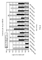
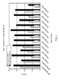
Figure 6 is a bar chart showing the ultimate tensile strength and the 0.2% proof strength in tensile tests for fine grained RR1000 processed conventionally and according to the present invention. -
Figure 7 is a bar chart showing the percentage elongation and the percentage reduction in area in tensile tests for fine grained RR1000 processed conventionally and according to the present invention. -
Figure 8 is a bar chart showing the ultimate tensile strength and the 0.2% proof strength in tensile tests for coarse grained RR1000 processed conventionally and according to the present invention. -
Figure 9 is a bar chart showing the percentage elongation and the percentage reduction in area in tensile tests for coarse grained RR1000 processed conventionally and according to the present invention. -
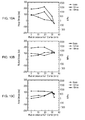
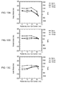
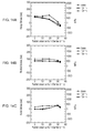
Figures 10A, 10B and 10C are graphs showing the hoop stress, radial stress and axial stress in test pieces at different axial and radial positions in a first cylindrical test piece which was water quenched only. -
Figures 11A, 11B and 11C are graphs showing the hoop stress, radial stress and axial stress in test pieces at different axial and radial positions in a second cylindrical test piece which was water quenched, aged and given a low deformation. -
Figures 12A, 12B and 12C are graphs showing the hoop stress, radial stress and axial stress in test pieces at different axial and radial positions in a third cylindrical test piece which was water quenched and given a high deformation. -
Figures 13A, 13B and 13C are graphs showing the hoop stress, radial stress and axial stress in test pieces at different axial and radial positions in a fourth cylindrical test piece which was water quenched and given a low deformation. -
Figures 14A, 14B and 14C are graphs showing the hoop stress, radial stress and axial stress in test pieces at different axial and radial positions in a fifth cylindrical test piece which was oil quenched, aged and given a medium deformation. -
Figures 15A, 15B and 15C are graphs showing the hoop stress, radial stress and axial stress in test pieces at different axial and radial positions in a sixth cylindrical test piece which was oil quenched and aged. - A turbofan
gas turbine engine 10, as shown infigure 1 , comprises in axial flow series an intake 12, afan section 14, acompressor section 16, acombustion section 18, aturbine section 20 and anexhaust 22. Theturbine section 20 comprises aturbine disc 24, which carries a plurality of circumferentiallyspace turbine blades 26. The gas turbine engine is quite conventional and its construction and operation will not be described further. - The gas turbine
engine turbine disc 24, as shown more clearly infigure 2 , comprises a hub, or cob, 26, aweb 28 and arim 30. Thehub 26 is at the radially inner end of theturbine disc 24, therim 30 is at the radially outer end of theturbine disc 24 and theweb 28 extends radially between and interconnects thehub 26 and therim 30. Therim 30, in this example, has a plurality of circumferentially spacedslots 34 to receive the roots ofturbine blades 26, shown infigure 1 , and circumferentially spacedposts 32 are provided on therim 30 of theturbine disc 24 to define the sides of theslots 34. Theslots 34 may be firtree shape, or dovetail shape. Theturbine disc 24 comprises a high strength nickel base superalloy, for example RR1000. - A
first method 40 of improving the mechanical properties of a component, for example a gas turbine engine turbine disc, 24 according to the present invention, as shown infigure 3 , comprises isothermally forging 42 a preform to produce a shaped preform with a predetermined shape at a first predetermined temperature, solution heat treating 44 the shaped preform, quenching 46 the shaped preform, forging 48 the shaped preform at a second predetermined temperature to impart a predetermined residual strain in the shaped preform, ageing 50 the shaped preform and finally machining 52 the shaped preform to a finished shape. It is to be noted that the second predetermined temperature is less than the first predetermined temperature. - A
second method 40B of improving the mechanical properties of a component, for example a gas turbine engine turbine disc, 24 according to the present invention, as shown infigure 4 , comprises isothermally forging 42 a preform to produce a shaped preform with a predetermined shape at a first predetermined temperature, solution heat treating 44 the shaped preform, quenching 46 the shaped preform, ageing 50 the shaped preform, forging 48 the shaped preform at a second predetermined temperature to impart a predetermined residual strain in the shaped preform and finally machining 52 the shaped preform to a finished shape. It is to be noted that the second predetermined temperature is less than the first predetermined temperature. - A
third method 40C of improving the mechanical properties of a component, for example a gas turbine engine turbine disc, 24 according to the present invention, as shown infigure 5 , comprises isothermally forging 42 a preform to produce a shaped preform with a predetermined shape at a first predetermined temperature, solution heat treating 44 the shaped preform, quenching 46 the shaped preform, simultaneously forging 48 the shaped preform at a second predetermined temperature to impart a predetermined residual strain in the shaped preform andageing 50 the shaped preform and finally machining 52 the shaped preform to a finished shape. It is to be noted that the second predetermined temperature is less than the first predetermined temperature. - In the three methods discussed above the second predetermined temperature is between 700°C and 870°C (1300°F and 1600°F), more preferably the second predetermined temperature is between 750°C and 850°C (1380°F and 1560°F), even more preferably 760°C to 810°C (1400°F to 1490°F). The forging 48 step may be arranged to impart a predetermined residual tensile strain or a predetermined residual compressive strain. The forging 48 step imparts a strain of less than or equal to 15%, e.g. 5% or 10% strain.
- The three methods mention above may comprise machining the shaped preform after the isothermal forging 42 and before the
solution heat treatment 44. - Although the three methods mentioned previously have mentioned a gas turbine engine turbine disc, the component may be a compressor disc, a compressor cone or a turbine cover plate. The component may comprise a nickel base superalloy, a titanium base alloy or other suitable alloy.
- The preform used in the previously mentioned methods may have been made by a cast and a wrought route or alternatively may have been made by a powder processing route.
- The forging 48 may comprise isothermal forging, hot die press forging or hammer forging and the forging 48 may comprise applying a mechanical load, a fluid load or a thermal gradient via any conventional forging apparatus or process. The isothermal forging may use an isothermal forging press and the die for the isothermal forging press may comprise TZM molybdenum or other suitable material.
- The
final machining 52 may comprise any suitable machining, e.g. turning, grinding, milling, drilling, polishing etc. - The isothermal forging 42 is preferred, but may be replaced by other suitable types of forging.
- The present invention is described more fully with reference to an example. RR1000 consists of 18.5wt% cobalt, 15wt% chromium, 5wt% molybdenum, 2wt% tantalum, 3.6wt% titanium, 3wt% aluminium, 0.5wt% hafnium, 0.015wt% boron, 0.06wt% zirconium, 0.027wt% carbon and the balance nickel plus incidental impurities. RR1000 has a gamma prime solvus temperature of 1145°C to 1150°C. Thus, a turbine, or compressor, disc consisting of RR1000 is produced by initially producing a billet, using either powder metallurgy, or cast and wrought, techniques.
- The RR1000 billet is then isothermally forged, at
step 42 infigure 3 , to produce a shaped preform which is near to the final shape of the disc at a temperature up to gamma prime solvus minus 25°C to 50°, at a strain rate between 1 x 10⁻⁴ and 1 x 10⁻² s-1 or at a temperature up to gamma prime solvus minus 55°C to 110°C at a strain rate between 1 x 10⁻² and 5 x 10⁻¹ s-1. The RR1000 shaped preform is then solution heat treated, atstep 44, at a temperature in the range of gamma prime solvus minus 15°C to 35°C up to gamma prime solvus plus 25°C to 60°C for times between 0.5 and 8 hours. The shaped preform is cooled or quenched, atstep 46, from the solution heat treatment temperature at a rate suitable to avoid quench cracking at stress concentrations, for example at a rate between 0.1 °C s-1 and 10°C s-1. The shaped preform is then isothermally forged, atstep 48, at a temperature between 700°C (1292°F) and 870°C (1598°F), at a strain rate between 1 x 10⁻⁴ and 1 x 10⁻² s-1 to impart a predetermined residual strain to the shaped preform. The shaped preform is then given an ageing heat treatment, atstep 50, at a temperature between 650°C (1202°F) and 800°C (1472°F) for between 2 and 30 hours. Finally the shaped preform is machined to final shape atstep 52. - A series of tests were carried out on samples of fine grained and coarse grained RR1000 nickel base superalloy, which were initially forged.
Samples 1 and 2 of RR1000 were given a conventional subsolvus solution heat treatment at 1120°C (2048°F) for 4 hours, then air cooled, followed by an ageing heat treatment at 760°C (1400°F) for 16 hours and then air cooled as a baseline. Other samples, samples 3 and 6, of RR1000 were given a subsolvus solution heat treatment at 1120°C (2048°F) for 4 hours, then air cooled, followed by an ageing heat treatment at 760°C (1400°F) for 16 hours and then strained at 760°C (1400°F) at 5% or 10% strain respectively. Other samples, samples 4 and 7, of RR1000 were given a subsolvus solution heat treatment at 1120°C (2048°F) for 4 hours, then air cooled, followed by an ageing heat treatment at 760°C (1400°F) for 16 hours and then strained at 802°C (1475°F) at 5% or 10% strain respectively. Other samples,samples 5, 22 and 8, of RR1000 were given a subsolvus solution heat treatment at 1120°C (2048°F) for 4 hours, then air cooled, followed by an ageing heat treatment at 760°C (1400°F) for 16 hours and then strained at 843°C (1550°F) at 5%, 10% or 15% strain respectively. Additional samples, samples 17 and 11, of RR1000 were given a subsolvus solution heat treatment at 1120°C (2048°F) for 4 hours, then air cooled, then strained at 760°C (1400°F) at 5% or 10% strain respectively, followed by an ageing heat treatment at 760°C (1400°F) for 16 hours. Another sample, sample 12, of RR1000 was given a subsolvus solution heat treatment at 1120°C (2048°F) for 4 hours, then air cooled, then strained at 802°C (1475°F) at 5% strain, followed by an ageing heat treatment at 760°C (1400°F) for 16 hours. Another sample, sample 13, of RR1000 was given a subsolvus solution heat treatment at 1120°C (2048°F) for 4 hours, then air cooled, then strained at 843°C (1550°F) at 5% strain, followed by an ageing heat treatment at 760°C (1400°F) for 16 hours. - Samples,
samples 9 and 10, of RR1000 were given a conventional subsolvus solution heat treatment at 1120°C (2048°F) for 4 hours, then air cooled, followed by a supersolvus heat treatment at 1204°C (2200°F) for 1 hour, then air cooled, followed by an ageing heat treatment at 760°C (1400°F) for 16 hours and air cooled as a baseline. Further samples,samples 14 and 19, of RR1000 were given a subsolvus solution heat treatment at 1120°C (2048°F) for 4 hours, then air cooled, followed by a supersolvus heat treatment at 1204°C (2200°F) for 1 hour, then air cooled, followed by an ageing heat treatment at 760°C (1400°F) for 16 hours and then strained at 760°C (1400°F) at 5% or 10% strain respectively. Other samples,samples 15 and 20, of RR1000 were given a subsolvus solution heat treatment at 1120°C (2048°F) for 4 hours, then air cooled, followed by a supersolvus heat treatment at 1204°C (2200°F) for 1 hour, then air cooled, followed by an ageing heat treatment at 760°C (1400°F) for 16 hours and then strained at 802°C (1475°F) at 5% or 10% strain respectively. Other samples,samples - In all cases the samples were held at the appropriate temperature for 1 hour before any strain was applied.
- The subsolvus heat treatment, followed by ageing heat treatment produced fine grains in the nickel base superalloy and the subsolvus heat treatment, followed by the supersolvus heat treatment and ageing heat treatment produced coarse grains in the nickel base superalloy as is well known to those skilled in the art.
- Then standard test pieces were taken from each of the large samples of RR1000 and the test pieces of the samples were then subjected to tensile tests at a temperature of 650°C (1202°F) to determine the ultimate tensile strength and the 0.2% proof strength of the samples and to determine the percentage elongation and percentage reduction in area of the samples. The results are recorded in Table A below and some of the results are shown in
figures 6 ,7 ,8 and9 .Table A Sample Thermal Strain Temp (°F) Strain (%) Ultimate 0.2% Tensile Strength (MPa) % % History Proof Strength (MPa) Elong Red
Area1 Sb + A - - 1382 1004 25 35 2 Sb + A - - 1381 1000 21 25 3 Sb + A + St 1400 5 1502 1211 12 37 4 Sb + A + St 1475 5 1484 1251 17 26 5 Sb + A + St 1550 5 1464 1176 22 36 6 Sb + A + St 1400 10 1598 1365 9 34 7 Sb + A + St 1475 10 1503 1249 13 33 22 Sb + A + St 1550 10 1499 1265 16 38 8 Sb + A + St 1400 15.5 1487 1138 13 31 17 Sb + St + A 1400 5 1549 1277 15 27 12 Sb + St + A 1475 5 1489 1238 15 34 13 Sb + St + A 1550 5 1462 1225 21 33 11 Sb + St + A 1400 10 1498 1229 7 15 9 Sb+Su + A + St - - 1356 846 22 25 10 Sb+Su + A + St - - 1365 852 22 24 14 Sb+Su + A + St 1400 5 1494 1209 9 18 23 Sb+Su + A + St 1550 5 1431 1129 13 27 19 Sb+Su + A + St 1400 10 1485 1240 4 12 20 Sb+Su + A + St 1475 10 1476 1218 9 17 24 Sb+Su + A + St 1550 10 1541 1253 11 29 (Sb - subsolvus heat treatment, Su - supersolvus heat treatment, A - ageing heat treatment, St - strain heat treatment) - The above results show that the present invention has increased the ultimate tensile strength and the 0.2% proof strength of a fine grained nickel base superalloy above that of a fine grained nickel base superalloy given a conventional subsolvus heat treatment followed by an ageing heat treatment. The above results show that the present invention has increased the ultimate tensile strength and the 0.2% proof strength of a coarse grained nickel base superalloy above that of a nickel base superalloy given a conventional subsolvus heat treatment, followed by a supersolvus heat treatment followed by an ageing heat treatment.
- Another series of tests were carried out on samples of RR1000 nickel base superalloy, which were initially forged. This series of tests used the method described with respect to
figure 4 . The quenching,step 46, of the nickel base superalloy was chosen to be either an oil quench or a water quench to impart a high level of strain into the isothermally forged,step 42, and solution heat treated,step 44, nickel base superalloy. The ageing heat treatment,step 50, was a conventional age at 760 °C (1400°F) for 16 hours. The isothermal forging,step 48, was conducted within the preferred temperature range at a temperature less than 760°C (1400°F). - In order to investigate the effect of strain, three different strain values were investigated. Residual stress was measured using a neutron diffraction technique, which allows for non-destructive evaluation of the nickel base superalloys. The residual stresses were measured at a number of locations in three different orientations, the orientations were hoop, axial and radial. The test pieces were cylindrical and nominally had a diameter of 75mm and a height, or thickness, of 25mm. The residual stress was measured at locations at 5mm, 12mm and 19mm height from one face of the cylindrical test piece and at radial locations of 0mm, 10mm, 19mm, 30 and 33mm from the centre of the cylindrical test piece. Table B shows the residual hoop stress levels, in MPa, at different radial locations at a height of 12mm from the surface of the cylindrical test pieces, for different quenching, ageing and deformation conditions. All the deformations are less than or equal to 10% strain.
TABLE B Test Quench Age Deformation Height Radial Position (mm) Piece (mm) 0 10 19 30 33 1 Water - - 12 1300 1400 1550 500 -300 2 Water Aged Low 12 675 750 850 350 0 3 Water - High 12 250 260 400 510 480 4 Water - Low 12 1000 1000 1200 600 -200 5 Oil Aged Medium 12 700 725 760 175 -200 6 Oil Aged - 12 750 - 800 - -250 Test piece 2, which was water quenched, aged and given a low deformation has a much lower levels of residual stress at all radial positions compared to test piece 1 due to the combination of a conventional age and a low deformation and low temperature mechanical stress relief. Test piece 4, which was water quenched and given a low deformation has levels of residual stress intermediate that oftest pieces 1 and 2 except for the 30mm radial position. Test piece 3, which was water quenched and given a high deformation has lower levels of residual stress thantest piece 2 at the 0mm, 10mm and 19mm radial locations. Comparingtest pieces 1, 2 and 4 it can be seen that the deformation alone and the ageing and deformation produce a reduction in the residual stress and therefore that the combination of deformation and ageing produces a greater reduction in the residual stress. Test piece 5, which was oil quenched, aged and given a medium deformation has lower levels of residual stress than test piece 6, which was oil quenched and aged.Figures 10 to 15 are graphs showing the hoop stress, radial stress and axial stress fortest pieces 1, 2, 3, 4, 5 and 6 respectively at locations at 5mm, 12mm and 19mm axially, height, from one face of the cylindrical test piece and at radial locations of 0mm, 10mm, 19mm, 30 and 33mm from the centre of the cylindrical test piece. This data shows the effectiveness of the present invention at controlling the residual stresses. - The present invention allows the imparted strain levels to be accurately controlled. The present invention is applicable to components with all microstructures commonly found in nickel base superalloy components, e.g. fine grains, medium grains, coarse grains or dual microstructures. The present invention is applicable to high strength nickel base superalloys for example RR1000, U720Li, Rene 95, Rene 88DT, ME3, N18,
Alloy 10 and LSHR. - U720Li consists of 15wt% cobalt, 16wt% chromium, 3wt% molybdenum, 1.25wt% tungsten, 5wt% titanium, 2.5wt% aluminium, 0.015wt% boron, 0.015wt% carbon and the balance nickel plus incidental impurities.
- Rene 95 consists of 8.12t% cobalt, 12.94wt% chromium, 3.45wt% molybdenum, 3.43wt% tungsten, 2.44wt% titanium, 3.42wt% aluminium, 3.37wt% niobium, 0.012wt% boron, 0.05wt% zirconium, 0.07wt% carbon and the balance nickel plus incidental impurities.
- Rene 88DT consists of 13.1wt% cobalt, 15.8wt% chromium, 4wt% molybdenum, 3.9wt% tungsten, 3.7wt% titanium, 2wt% aluminium, 0.7wt% niobium, 0.016wt% boron, 0.045wt% zirconium, 0.05wt% carbon and the balance nickel plus incidental impurities.
- ME3 consists of 20.6wt% cobalt, 13wt% chromium, 3.8wt% molybdenum, 2.1wt% tungsten, 2.4wt% tantalum, 3.7wt% titanium, 3.4wt% aluminium, 0.03wt% boron, 0.05wt% zirconium, 0.04wt% carbon and the balance nickel plus incidental impurities.
- N18 consists of 15.4wt% cobalt, 11.1wt% chromium, 6.44wt% molybdenum, 4.28wt% titanium, 4.28wt% aluminium, 0.5wt% hafnium, 0.008wt% boron, 0.019wt% zirconium, 0.022wt% carbon and the balance nickel plus incidental impurities.
-
Alloy 10 consists of 17.93wt% cobalt, 10.46wt% chromium, 2.52wt% molybdenum, 4.74wt% tungsten, 1.61wt% tantalum, 3.79wt% titanium, 3.53wt% aluminium, 0.028wt% boron, 0.07wt% zirconium, 0.027wt% carbon and the balance nickel plus incidental impurities. - LSHR consists of 20.8wt% cobalt, 12.7wt% chromium, 2.74wt% molybdenum, 4.37wt% tungsten, 1.65wt% tantalum, 3.47wt% titanium, 3.48wt% aluminium, 0.028wt% boron, 0.049wt% zirconium, 0.024wt% carbon and the balance nickel plus incidental impurities.
- The present invention is also applicable to titanium base alloys, for example Ti6246, Ti6242 or other alloys where increased tensile properties or creep properties are required.
- The present invention may be used to reduce, or eliminate, residual stresses developed by the solution heat treatment process. The present invention may be used to produce unique residual stress profiles in a component. The present invention may be used to support increased precipitation kinetics if it is applied before the ageing. The present invention may be used to selectively alter the retained strain or precipitation kinetics within a superalloy disc. The present invention increases the mechanical strength of the alloy component by introducing dislocations, structural disturbances to the crystal structure, which in turn present obstacles to the creation and movement of further dislocations and hence increases mechanical strength.
- The present invention enables turbine discs, compressor discs, compressor cones or turbine cover plates to be produced with enhanced proof and tensile strength and creep properties or reduced residual stress levels. This enables an increase in the operating life of the component, enables an increase in the operating rotational speed of the component, enables a decrease in the size of the component for an identical gas turbine engine cycle or enables a reduction in weight of the component for the same operating life. The improved properties allow an increase in overspeed capability.
Claims (17)
- A method of improving the mechanical properties of a component (24) comprising the steps of:a) forging (42) a preform to produce a shaped preform with a predetermined shape at a first predetermined temperature,b) solution heat treating (44) the shaped preform,c) quenching (46) the shaped preform,d) ageing (50) the shaped preform,e) machining (52) the shaped preform to a finished shape or a semi-finished shape, characterised byf) forging (48) the shaped preform at a second predetermined temperature to impart a predetermined residual strain in the shaped preform after step c) and before step e), wherein the second predetermined temperature is less than the first predetermined temperature.
- A method as claimed in claim 1 wherein step f) is after step c) and before step d), step f) is after step d) and before step e) or step f) is concurrent with step d).
- A method as claimed in claim 1 or claim 2 wherein the second predetermined temperature is between 700°C and 870°C.
- A method as claimed in claim 3 wherein the second predetermined temperature is between 760°C and 810°C.
- A method as claimed in any of claims 1 to 4 wherein the forging step f) imparts a predetermined residual tensile strain or a predetermined residual compressive strain.
- A method as claimed in any of claims 1 to 5 wherein the forging step f) imparts a strain of less than 10%.
- A method as claimed in any of claims 1 to 6 wherein the method comprises machining the shaped preform after step a) and before step b).
- A method as claimed in any of claims 1 to 7 wherein step f) comprises isothermally forging.
- A method as claimed in any of claims 1 to 8 wherein step f) comprises forging at a strain rate between 1 x 10⁻⁴ and 1 x 10⁻² s-1.
- A method as claimed in any of claims 1 to 9 wherein step a) comprises isothermally forging.
- A method as claimed in any of claims 1 to 10 wherein in step a) the first predetermined temperature is up to gamma prime solvus minus 25°C to 50°C and step a) comprises forging at a strain rate between 1 x 10⁻⁴ and 1 x 10⁻² s-1.
- A method as claimed in any of claims 1 to 10 wherein in step a) the first predetermined temperature is up to gamma prime solvus minus 55°C to 110°C and step a) comprises forging at a strain rate between 1 x 10⁻² and 5 x 10⁻¹ s-1.
- A method as claimed in any of claims 1 to 12 wherein step b) comprises a subsolvus solution heat treatment and or a supersolvus heat treatment.
- A method as claimed in claim 13 wherein step b) comprises a subsolvus solution heat treatment at 1120°C for 4 hours, a subsolvus solution heat treatment at 1120°C for 4 hours, followed by quenching, followed by a supersolvus heat treatment at 1204°C for 1 hour or a supersolvus heat treatment at 1204°C for 1 hour.
- A method as claimed in any of claims 1 to 14 wherein step d) comprises an ageing heat treatment at 760°C for 16 hours.
- A method as claimed in any of claims 1 to 15 wherein the component is a compressor disc, a turbine disc, a compressor cone or a turbine cover plate.
- A method as claimed in any of claims 1 to 16 wherein the component comprises a nickel base superalloy or a titanium base alloy.
Applications Claiming Priority (1)
| Application Number | Priority Date | Filing Date | Title |
|---|---|---|---|
| US36337610P | 2010-07-12 | 2010-07-12 |
Publications (2)
| Publication Number | Publication Date |
|---|---|
| EP2407565A1 true EP2407565A1 (en) | 2012-01-18 |
| EP2407565B1 EP2407565B1 (en) | 2013-05-08 |
Family
ID=44936956
Family Applications (1)
| Application Number | Title | Priority Date | Filing Date |
|---|---|---|---|
| EP11170184.3A Not-in-force EP2407565B1 (en) | 2010-07-12 | 2011-06-16 | A method of improving the mechanical properties of a component |
Country Status (2)
| Country | Link |
|---|---|
| US (1) | US20120006452A1 (en) |
| EP (1) | EP2407565B1 (en) |
Cited By (7)
| Publication number | Priority date | Publication date | Assignee | Title |
|---|---|---|---|---|
| EP2578331A1 (en) * | 2011-10-06 | 2013-04-10 | Rolls-Royce plc | Method and equipment for shaping a cast component |
| EP2876172A1 (en) * | 2013-11-26 | 2015-05-27 | MTU Aero Engines GmbH | Method for producing and repairing components of a turbo engine made from nickel-based superalloys |
| WO2015126487A3 (en) * | 2013-12-17 | 2015-10-29 | United Technologies Corporation | Abrasively machined gas turbine components |
| US10138534B2 (en) | 2015-01-07 | 2018-11-27 | Rolls-Royce Plc | Nickel alloy |
| US10266919B2 (en) | 2015-07-03 | 2019-04-23 | Rolls-Royce Plc | Nickel-base superalloy |
| US10309229B2 (en) | 2014-01-09 | 2019-06-04 | Rolls-Royce Plc | Nickel based alloy composition |
| EP3543369A4 (en) * | 2016-11-16 | 2020-04-29 | Mitsubishi Hitachi Power Systems, Ltd. | METHOD FOR MANUFACTURING NICKEL ALLOY HIGH TEMPERATURE MATERIAL |
Families Citing this family (8)
| Publication number | Priority date | Publication date | Assignee | Title |
|---|---|---|---|---|
| US20130221794A1 (en) * | 2012-02-28 | 2013-08-29 | Hamilton Sundstrand Corporation | Rotor end band |
| US10364677B2 (en) * | 2013-03-15 | 2019-07-30 | United Technologies Corporation | Turbine engine hybrid rotor |
| DE102015206323A1 (en) * | 2015-04-09 | 2016-10-13 | Siemens Aktiengesellschaft | Component with strength gradients, method and turbine |
| JP6809170B2 (en) | 2016-11-28 | 2021-01-06 | 大同特殊鋼株式会社 | Manufacturing method of Ni-based superalloy material |
| JP6809169B2 (en) * | 2016-11-28 | 2021-01-06 | 大同特殊鋼株式会社 | Manufacturing method of Ni-based superalloy material |
| CN110438424A (en) * | 2019-07-31 | 2019-11-12 | 河钢股份有限公司 | A kind of low temperature deformation reinforcing heat treatment method of nickel-base alloy GH4169 |
| ES2987264T3 (en) * | 2020-03-30 | 2024-11-14 | Itp Engines Uk Ltd | Forged rotary disc for a rotor wheel with blades and method of manufacturing the same |
| CN114214510B (en) * | 2021-12-28 | 2024-02-06 | 北京钢研高纳科技股份有限公司 | Method for removing residual stress in high-temperature alloy part through vibration aging and application of method |
Citations (5)
| Publication number | Priority date | Publication date | Assignee | Title |
|---|---|---|---|---|
| GB1253861A (en) * | 1967-12-22 | 1971-11-17 | United Aircraft Corp | Improvements in and relating to fabricating methods for high strength alloys |
| EP1892307A1 (en) * | 2006-08-25 | 2008-02-27 | Hitachi, Ltd. | Ni-Fe based forging superalloy excellent in high-temperature strength and high-temperature ductility, method of manufacturing the same, and steam turbine rotor |
| EP2039789A1 (en) * | 2007-09-14 | 2009-03-25 | Kabushiki Kaisha Toshiba | Nickel-based alloy for turbine rotor of steam turbine and turbine rotor of steam turbine |
| EP2233594A1 (en) * | 2009-03-18 | 2010-09-29 | Kabushiki Kaisha Toshiba | Nickel-base alloy for a steam turbine rotor and steam turbine rotor thereof |
| EP2312000A1 (en) * | 2009-10-15 | 2011-04-20 | Rolls-Royce plc | A method of forging a nickel base superalloy |
-
2011
- 2011-06-16 EP EP11170184.3A patent/EP2407565B1/en not_active Not-in-force
- 2011-06-16 US US13/162,205 patent/US20120006452A1/en not_active Abandoned
Patent Citations (5)
| Publication number | Priority date | Publication date | Assignee | Title |
|---|---|---|---|---|
| GB1253861A (en) * | 1967-12-22 | 1971-11-17 | United Aircraft Corp | Improvements in and relating to fabricating methods for high strength alloys |
| EP1892307A1 (en) * | 2006-08-25 | 2008-02-27 | Hitachi, Ltd. | Ni-Fe based forging superalloy excellent in high-temperature strength and high-temperature ductility, method of manufacturing the same, and steam turbine rotor |
| EP2039789A1 (en) * | 2007-09-14 | 2009-03-25 | Kabushiki Kaisha Toshiba | Nickel-based alloy for turbine rotor of steam turbine and turbine rotor of steam turbine |
| EP2233594A1 (en) * | 2009-03-18 | 2010-09-29 | Kabushiki Kaisha Toshiba | Nickel-base alloy for a steam turbine rotor and steam turbine rotor thereof |
| EP2312000A1 (en) * | 2009-10-15 | 2011-04-20 | Rolls-Royce plc | A method of forging a nickel base superalloy |
Cited By (11)
| Publication number | Priority date | Publication date | Assignee | Title |
|---|---|---|---|---|
| EP2578331A1 (en) * | 2011-10-06 | 2013-04-10 | Rolls-Royce plc | Method and equipment for shaping a cast component |
| US9133539B2 (en) | 2011-10-06 | 2015-09-15 | Rolls-Royce Plc | Method and equipment for shaping a cast component |
| EP2876172A1 (en) * | 2013-11-26 | 2015-05-27 | MTU Aero Engines GmbH | Method for producing and repairing components of a turbo engine made from nickel-based superalloys |
| WO2015126487A3 (en) * | 2013-12-17 | 2015-10-29 | United Technologies Corporation | Abrasively machined gas turbine components |
| US10309229B2 (en) | 2014-01-09 | 2019-06-04 | Rolls-Royce Plc | Nickel based alloy composition |
| US10138534B2 (en) | 2015-01-07 | 2018-11-27 | Rolls-Royce Plc | Nickel alloy |
| US10266919B2 (en) | 2015-07-03 | 2019-04-23 | Rolls-Royce Plc | Nickel-base superalloy |
| US10422024B2 (en) | 2015-07-03 | 2019-09-24 | Rolls-Royce Plc | Nickel-base superalloy |
| EP3543369A4 (en) * | 2016-11-16 | 2020-04-29 | Mitsubishi Hitachi Power Systems, Ltd. | METHOD FOR MANUFACTURING NICKEL ALLOY HIGH TEMPERATURE MATERIAL |
| US11021780B2 (en) | 2016-11-16 | 2021-06-01 | Mitsubishi Power, Ltd. | Method for manufacturing nickel-based alloy high-temperature component |
| US11401597B2 (en) | 2016-11-16 | 2022-08-02 | Mitsubishi Heavy Industries, Ltd. | Method for manufacturing nickel-based alloy high-temperature component |
Also Published As
| Publication number | Publication date |
|---|---|
| EP2407565B1 (en) | 2013-05-08 |
| US20120006452A1 (en) | 2012-01-12 |
Similar Documents
| Publication | Publication Date | Title |
|---|---|---|
| EP2407565B1 (en) | A method of improving the mechanical properties of a component | |
| EP1382706B1 (en) | Isothermal forging of nickel-base superalloys in air | |
| EP2019150A1 (en) | Method of controlling and refining final grain size in supersolvus heat treated nickel-base superalloys | |
| JP5554468B2 (en) | Method for controlling final crystal grain size of supersolvus heat-treated nickel-base superalloy and product formed by the method | |
| US9322090B2 (en) | Components formed by controlling grain size in forged precipitation-strengthened alloys | |
| EP1416062B1 (en) | Quasi-Isothermal forging of a nickel-base superalloy | |
| EP0533918B1 (en) | Superalloy forging process and related composition | |
| JP6252704B2 (en) | Method for producing Ni-base superalloy | |
| JP6150192B2 (en) | Method for producing Ni-base superalloy | |
| US11718897B2 (en) | Precipitation hardenable cobalt-nickel base superalloy and article made therefrom | |
| EP2256222B1 (en) | Nickel-base superalloys and components formed thereof | |
| EP3387158B1 (en) | Methods for processing nickel-base alloys | |
| EP2281907A1 (en) | Nickel-Base Superalloys and Components Formed Thereof | |
| EP0849370A1 (en) | High strength nickel base superalloy articles having machined surfaces | |
| US5571345A (en) | Thermomechanical processing method for achieving coarse grains in a superalloy article | |
| EP0533914B1 (en) | Superalloy forging process and related composition | |
| EP1524325B1 (en) | Method for reducing heat treatment residual stresses in super-solvus solutioned nickel-base superalloy articles | |
| US5415712A (en) | Method of forging in 706 components | |
| EP2283952A2 (en) | Powder metal mold | |
| Donachie | A guide to engineering selection of titanium alloys for design |
Legal Events
| Date | Code | Title | Description |
|---|---|---|---|
| AK | Designated contracting states |
Kind code of ref document: A1 Designated state(s): AL AT BE BG CH CY CZ DE DK EE ES FI FR GB GR HR HU IE IS IT LI LT LU LV MC MK MT NL NO PL PT RO RS SE SI SK SM TR |
|
| AX | Request for extension of the european patent |
Extension state: BA ME |
|
| PUAI | Public reference made under article 153(3) epc to a published international application that has entered the european phase |
Free format text: ORIGINAL CODE: 0009012 |
|
| 17P | Request for examination filed |
Effective date: 20120524 |
|
| RIC1 | Information provided on ipc code assigned before grant |
Ipc: C22C 14/00 20060101ALI20120829BHEP Ipc: C22C 1/02 20060101AFI20120829BHEP Ipc: C22F 1/18 20060101ALI20120829BHEP Ipc: C22C 19/05 20060101ALI20120829BHEP Ipc: C22C 19/03 20060101ALI20120829BHEP Ipc: C22F 1/10 20060101ALI20120829BHEP |
|
| GRAP | Despatch of communication of intention to grant a patent |
Free format text: ORIGINAL CODE: EPIDOSNIGR1 |
|
| GRAS | Grant fee paid |
Free format text: ORIGINAL CODE: EPIDOSNIGR3 |
|
| GRAA | (expected) grant |
Free format text: ORIGINAL CODE: 0009210 |
|
| AK | Designated contracting states |
Kind code of ref document: B1 Designated state(s): AL AT BE BG CH CY CZ DE DK EE ES FI FR GB GR HR HU IE IS IT LI LT LU LV MC MK MT NL NO PL PT RO RS SE SI SK SM TR |
|
| REG | Reference to a national code |
Ref country code: GB Ref legal event code: FG4D |
|
| REG | Reference to a national code |
Ref country code: AT Ref legal event code: REF Ref document number: 611145 Country of ref document: AT Kind code of ref document: T Effective date: 20130515 Ref country code: CH Ref legal event code: EP |
|
| REG | Reference to a national code |
Ref country code: IE Ref legal event code: FG4D |
|
| REG | Reference to a national code |
Ref country code: DE Ref legal event code: R096 Ref document number: 602011001611 Country of ref document: DE Effective date: 20130704 |
|
| REG | Reference to a national code |
Ref country code: AT Ref legal event code: MK05 Ref document number: 611145 Country of ref document: AT Kind code of ref document: T Effective date: 20130508 |
|
| REG | Reference to a national code |
Ref country code: LT Ref legal event code: MG4D |
|
| REG | Reference to a national code |
Ref country code: NL Ref legal event code: VDEP Effective date: 20130508 |
|
| PG25 | Lapsed in a contracting state [announced via postgrant information from national office to epo] |
Ref country code: SI Free format text: LAPSE BECAUSE OF FAILURE TO SUBMIT A TRANSLATION OF THE DESCRIPTION OR TO PAY THE FEE WITHIN THE PRESCRIBED TIME-LIMIT Effective date: 20130508 Ref country code: FI Free format text: LAPSE BECAUSE OF FAILURE TO SUBMIT A TRANSLATION OF THE DESCRIPTION OR TO PAY THE FEE WITHIN THE PRESCRIBED TIME-LIMIT Effective date: 20130508 Ref country code: AT Free format text: LAPSE BECAUSE OF FAILURE TO SUBMIT A TRANSLATION OF THE DESCRIPTION OR TO PAY THE FEE WITHIN THE PRESCRIBED TIME-LIMIT Effective date: 20130508 Ref country code: IS Free format text: LAPSE BECAUSE OF FAILURE TO SUBMIT A TRANSLATION OF THE DESCRIPTION OR TO PAY THE FEE WITHIN THE PRESCRIBED TIME-LIMIT Effective date: 20130908 Ref country code: PT Free format text: LAPSE BECAUSE OF FAILURE TO SUBMIT A TRANSLATION OF THE DESCRIPTION OR TO PAY THE FEE WITHIN THE PRESCRIBED TIME-LIMIT Effective date: 20130909 Ref country code: SE Free format text: LAPSE BECAUSE OF FAILURE TO SUBMIT A TRANSLATION OF THE DESCRIPTION OR TO PAY THE FEE WITHIN THE PRESCRIBED TIME-LIMIT Effective date: 20130508 Ref country code: NO Free format text: LAPSE BECAUSE OF FAILURE TO SUBMIT A TRANSLATION OF THE DESCRIPTION OR TO PAY THE FEE WITHIN THE PRESCRIBED TIME-LIMIT Effective date: 20130808 Ref country code: LT Free format text: LAPSE BECAUSE OF FAILURE TO SUBMIT A TRANSLATION OF THE DESCRIPTION OR TO PAY THE FEE WITHIN THE PRESCRIBED TIME-LIMIT Effective date: 20130508 Ref country code: GR Free format text: LAPSE BECAUSE OF FAILURE TO SUBMIT A TRANSLATION OF THE DESCRIPTION OR TO PAY THE FEE WITHIN THE PRESCRIBED TIME-LIMIT Effective date: 20130809 Ref country code: ES Free format text: LAPSE BECAUSE OF FAILURE TO SUBMIT A TRANSLATION OF THE DESCRIPTION OR TO PAY THE FEE WITHIN THE PRESCRIBED TIME-LIMIT Effective date: 20130819 |
|
| PG25 | Lapsed in a contracting state [announced via postgrant information from national office to epo] |
Ref country code: BG Free format text: LAPSE BECAUSE OF FAILURE TO SUBMIT A TRANSLATION OF THE DESCRIPTION OR TO PAY THE FEE WITHIN THE PRESCRIBED TIME-LIMIT Effective date: 20130808 Ref country code: PL Free format text: LAPSE BECAUSE OF FAILURE TO SUBMIT A TRANSLATION OF THE DESCRIPTION OR TO PAY THE FEE WITHIN THE PRESCRIBED TIME-LIMIT Effective date: 20130508 Ref country code: HR Free format text: LAPSE BECAUSE OF FAILURE TO SUBMIT A TRANSLATION OF THE DESCRIPTION OR TO PAY THE FEE WITHIN THE PRESCRIBED TIME-LIMIT Effective date: 20130508 Ref country code: RS Free format text: LAPSE BECAUSE OF FAILURE TO SUBMIT A TRANSLATION OF THE DESCRIPTION OR TO PAY THE FEE WITHIN THE PRESCRIBED TIME-LIMIT Effective date: 20130508 Ref country code: CY Free format text: LAPSE BECAUSE OF FAILURE TO SUBMIT A TRANSLATION OF THE DESCRIPTION OR TO PAY THE FEE WITHIN THE PRESCRIBED TIME-LIMIT Effective date: 20130508 |
|
| PG25 | Lapsed in a contracting state [announced via postgrant information from national office to epo] |
Ref country code: LV Free format text: LAPSE BECAUSE OF FAILURE TO SUBMIT A TRANSLATION OF THE DESCRIPTION OR TO PAY THE FEE WITHIN THE PRESCRIBED TIME-LIMIT Effective date: 20130508 |
|
| PG25 | Lapsed in a contracting state [announced via postgrant information from national office to epo] |
Ref country code: DK Free format text: LAPSE BECAUSE OF FAILURE TO SUBMIT A TRANSLATION OF THE DESCRIPTION OR TO PAY THE FEE WITHIN THE PRESCRIBED TIME-LIMIT Effective date: 20130508 Ref country code: CZ Free format text: LAPSE BECAUSE OF FAILURE TO SUBMIT A TRANSLATION OF THE DESCRIPTION OR TO PAY THE FEE WITHIN THE PRESCRIBED TIME-LIMIT Effective date: 20130508 Ref country code: EE Free format text: LAPSE BECAUSE OF FAILURE TO SUBMIT A TRANSLATION OF THE DESCRIPTION OR TO PAY THE FEE WITHIN THE PRESCRIBED TIME-LIMIT Effective date: 20130508 Ref country code: SK Free format text: LAPSE BECAUSE OF FAILURE TO SUBMIT A TRANSLATION OF THE DESCRIPTION OR TO PAY THE FEE WITHIN THE PRESCRIBED TIME-LIMIT Effective date: 20130508 Ref country code: BE Free format text: LAPSE BECAUSE OF FAILURE TO SUBMIT A TRANSLATION OF THE DESCRIPTION OR TO PAY THE FEE WITHIN THE PRESCRIBED TIME-LIMIT Effective date: 20130508 |
|
| PG25 | Lapsed in a contracting state [announced via postgrant information from national office to epo] |
Ref country code: NL Free format text: LAPSE BECAUSE OF FAILURE TO SUBMIT A TRANSLATION OF THE DESCRIPTION OR TO PAY THE FEE WITHIN THE PRESCRIBED TIME-LIMIT Effective date: 20130508 Ref country code: IT Free format text: LAPSE BECAUSE OF FAILURE TO SUBMIT A TRANSLATION OF THE DESCRIPTION OR TO PAY THE FEE WITHIN THE PRESCRIBED TIME-LIMIT Effective date: 20130508 Ref country code: RO Free format text: LAPSE BECAUSE OF FAILURE TO SUBMIT A TRANSLATION OF THE DESCRIPTION OR TO PAY THE FEE WITHIN THE PRESCRIBED TIME-LIMIT Effective date: 20130508 Ref country code: MC Free format text: LAPSE BECAUSE OF FAILURE TO SUBMIT A TRANSLATION OF THE DESCRIPTION OR TO PAY THE FEE WITHIN THE PRESCRIBED TIME-LIMIT Effective date: 20130508 |
|
| PLBE | No opposition filed within time limit |
Free format text: ORIGINAL CODE: 0009261 |
|
| STAA | Information on the status of an ep patent application or granted ep patent |
Free format text: STATUS: NO OPPOSITION FILED WITHIN TIME LIMIT |
|
| REG | Reference to a national code |
Ref country code: IE Ref legal event code: MM4A |
|
| 26N | No opposition filed |
Effective date: 20140211 |
|
| PG25 | Lapsed in a contracting state [announced via postgrant information from national office to epo] |
Ref country code: IE Free format text: LAPSE BECAUSE OF NON-PAYMENT OF DUE FEES Effective date: 20130616 |
|
| REG | Reference to a national code |
Ref country code: DE Ref legal event code: R097 Ref document number: 602011001611 Country of ref document: DE Effective date: 20140211 |
|
| REG | Reference to a national code |
Ref country code: CH Ref legal event code: PL |
|
| PG25 | Lapsed in a contracting state [announced via postgrant information from national office to epo] |
Ref country code: MT Free format text: LAPSE BECAUSE OF FAILURE TO SUBMIT A TRANSLATION OF THE DESCRIPTION OR TO PAY THE FEE WITHIN THE PRESCRIBED TIME-LIMIT Effective date: 20130508 |
|
| PG25 | Lapsed in a contracting state [announced via postgrant information from national office to epo] |
Ref country code: LI Free format text: LAPSE BECAUSE OF NON-PAYMENT OF DUE FEES Effective date: 20140630 Ref country code: CH Free format text: LAPSE BECAUSE OF NON-PAYMENT OF DUE FEES Effective date: 20140630 |
|
| PG25 | Lapsed in a contracting state [announced via postgrant information from national office to epo] |
Ref country code: SM Free format text: LAPSE BECAUSE OF FAILURE TO SUBMIT A TRANSLATION OF THE DESCRIPTION OR TO PAY THE FEE WITHIN THE PRESCRIBED TIME-LIMIT Effective date: 20130508 |
|
| REG | Reference to a national code |
Ref country code: FR Ref legal event code: PLFP Year of fee payment: 5 |
|
| PG25 | Lapsed in a contracting state [announced via postgrant information from national office to epo] |
Ref country code: TR Free format text: LAPSE BECAUSE OF FAILURE TO SUBMIT A TRANSLATION OF THE DESCRIPTION OR TO PAY THE FEE WITHIN THE PRESCRIBED TIME-LIMIT Effective date: 20130508 |
|
| PG25 | Lapsed in a contracting state [announced via postgrant information from national office to epo] |
Ref country code: MK Free format text: LAPSE BECAUSE OF FAILURE TO SUBMIT A TRANSLATION OF THE DESCRIPTION OR TO PAY THE FEE WITHIN THE PRESCRIBED TIME-LIMIT Effective date: 20130508 Ref country code: LU Free format text: LAPSE BECAUSE OF NON-PAYMENT OF DUE FEES Effective date: 20130616 Ref country code: HU Free format text: LAPSE BECAUSE OF FAILURE TO SUBMIT A TRANSLATION OF THE DESCRIPTION OR TO PAY THE FEE WITHIN THE PRESCRIBED TIME-LIMIT; INVALID AB INITIO Effective date: 20110616 |
|
| REG | Reference to a national code |
Ref country code: FR Ref legal event code: PLFP Year of fee payment: 6 |
|
| REG | Reference to a national code |
Ref country code: FR Ref legal event code: PLFP Year of fee payment: 7 |
|
| REG | Reference to a national code |
Ref country code: FR Ref legal event code: PLFP Year of fee payment: 8 |
|
| PG25 | Lapsed in a contracting state [announced via postgrant information from national office to epo] |
Ref country code: AL Free format text: LAPSE BECAUSE OF FAILURE TO SUBMIT A TRANSLATION OF THE DESCRIPTION OR TO PAY THE FEE WITHIN THE PRESCRIBED TIME-LIMIT Effective date: 20130508 |
|
| PGFP | Annual fee paid to national office [announced via postgrant information from national office to epo] |
Ref country code: FR Payment date: 20190625 Year of fee payment: 9 |
|
| PGFP | Annual fee paid to national office [announced via postgrant information from national office to epo] |
Ref country code: GB Payment date: 20190627 Year of fee payment: 9 Ref country code: DE Payment date: 20190627 Year of fee payment: 9 |
|
| REG | Reference to a national code |
Ref country code: DE Ref legal event code: R119 Ref document number: 602011001611 Country of ref document: DE |
|
| GBPC | Gb: european patent ceased through non-payment of renewal fee |
Effective date: 20200616 |
|
| PG25 | Lapsed in a contracting state [announced via postgrant information from national office to epo] |
Ref country code: GB Free format text: LAPSE BECAUSE OF NON-PAYMENT OF DUE FEES Effective date: 20200616 Ref country code: FR Free format text: LAPSE BECAUSE OF NON-PAYMENT OF DUE FEES Effective date: 20200630 |
|
| PG25 | Lapsed in a contracting state [announced via postgrant information from national office to epo] |
Ref country code: DE Free format text: LAPSE BECAUSE OF NON-PAYMENT OF DUE FEES Effective date: 20210101 |