EP2407295B1 - Resin molding apparatus and resin molding method - Google Patents
Resin molding apparatus and resin molding method Download PDFInfo
- Publication number
- EP2407295B1 EP2407295B1 EP10750882.2A EP10750882A EP2407295B1 EP 2407295 B1 EP2407295 B1 EP 2407295B1 EP 10750882 A EP10750882 A EP 10750882A EP 2407295 B1 EP2407295 B1 EP 2407295B1
- Authority
- EP
- European Patent Office
- Prior art keywords
- pair
- high frequency
- frequency current
- metal
- molding
- Prior art date
- Legal status (The legal status is an assumption and is not a legal conclusion. Google has not performed a legal analysis and makes no representation as to the accuracy of the status listed.)
- Active
Links
- 238000000465 moulding Methods 0.000 title claims description 110
- 229920005989 resin Polymers 0.000 title claims description 94
- 239000011347 resin Substances 0.000 title claims description 94
- 238000000034 method Methods 0.000 title claims description 18
- 239000002184 metal Substances 0.000 claims description 138
- 229910052751 metal Inorganic materials 0.000 claims description 138
- 239000000463 material Substances 0.000 claims description 65
- 229920005992 thermoplastic resin Polymers 0.000 claims description 34
- 239000011810 insulating material Substances 0.000 claims description 16
- 238000010438 heat treatment Methods 0.000 claims description 10
- 239000000835 fiber Substances 0.000 description 44
- 230000002787 reinforcement Effects 0.000 description 38
- 239000002131 composite material Substances 0.000 description 13
- 238000001746 injection moulding Methods 0.000 description 7
- 229920001169 thermoplastic Polymers 0.000 description 7
- 239000004416 thermosoftening plastic Substances 0.000 description 7
- 239000004745 nonwoven fabric Substances 0.000 description 6
- -1 Cr2N Chemical compound 0.000 description 5
- 238000001816 cooling Methods 0.000 description 4
- 239000010410 layer Substances 0.000 description 4
- 230000035699 permeability Effects 0.000 description 4
- 229910000831 Steel Inorganic materials 0.000 description 3
- 230000001965 increasing effect Effects 0.000 description 3
- 230000008569 process Effects 0.000 description 3
- 239000010959 steel Substances 0.000 description 3
- 229920000049 Carbon (fiber) Polymers 0.000 description 2
- XEEYBQQBJWHFJM-UHFFFAOYSA-N Iron Chemical compound [Fe] XEEYBQQBJWHFJM-UHFFFAOYSA-N 0.000 description 2
- CPLXHLVBOLITMK-UHFFFAOYSA-N Magnesium oxide Chemical compound [Mg]=O CPLXHLVBOLITMK-UHFFFAOYSA-N 0.000 description 2
- 230000009471 action Effects 0.000 description 2
- 239000004917 carbon fiber Substances 0.000 description 2
- 239000000919 ceramic Substances 0.000 description 2
- 238000000748 compression moulding Methods 0.000 description 2
- 230000003247 decreasing effect Effects 0.000 description 2
- 239000003365 glass fiber Substances 0.000 description 2
- 230000006872 improvement Effects 0.000 description 2
- 238000002844 melting Methods 0.000 description 2
- 230000008018 melting Effects 0.000 description 2
- 239000004033 plastic Substances 0.000 description 2
- 229920003023 plastic Polymers 0.000 description 2
- OKTJSMMVPCPJKN-UHFFFAOYSA-N Carbon Chemical compound [C] OKTJSMMVPCPJKN-UHFFFAOYSA-N 0.000 description 1
- 229910001018 Cast iron Inorganic materials 0.000 description 1
- CWYNVVGOOAEACU-UHFFFAOYSA-N Fe2+ Chemical compound [Fe+2] CWYNVVGOOAEACU-UHFFFAOYSA-N 0.000 description 1
- JHWNWJKBPDFINM-UHFFFAOYSA-N Laurolactam Chemical compound O=C1CCCCCCCCCCCN1 JHWNWJKBPDFINM-UHFFFAOYSA-N 0.000 description 1
- 239000004677 Nylon Substances 0.000 description 1
- 229920000299 Nylon 12 Polymers 0.000 description 1
- 229920003189 Nylon 4,6 Polymers 0.000 description 1
- 229920002292 Nylon 6 Polymers 0.000 description 1
- 229920002302 Nylon 6,6 Polymers 0.000 description 1
- 239000004697 Polyetherimide Substances 0.000 description 1
- 239000004698 Polyethylene Substances 0.000 description 1
- 239000004734 Polyphenylene sulfide Substances 0.000 description 1
- 239000004743 Polypropylene Substances 0.000 description 1
- 229920006362 Teflon® Polymers 0.000 description 1
- ATJFFYVFTNAWJD-UHFFFAOYSA-N Tin Chemical compound [Sn] ATJFFYVFTNAWJD-UHFFFAOYSA-N 0.000 description 1
- 229910001315 Tool steel Inorganic materials 0.000 description 1
- 239000004411 aluminium Substances 0.000 description 1
- 229910052782 aluminium Inorganic materials 0.000 description 1
- XAGFODPZIPBFFR-UHFFFAOYSA-N aluminium Chemical compound [Al] XAGFODPZIPBFFR-UHFFFAOYSA-N 0.000 description 1
- PNEYBMLMFCGWSK-UHFFFAOYSA-N aluminium oxide Inorganic materials [O-2].[O-2].[O-2].[Al+3].[Al+3] PNEYBMLMFCGWSK-UHFFFAOYSA-N 0.000 description 1
- 239000000498 cooling water Substances 0.000 description 1
- 230000005611 electricity Effects 0.000 description 1
- 230000005674 electromagnetic induction Effects 0.000 description 1
- 239000004744 fabric Substances 0.000 description 1
- 230000006698 induction Effects 0.000 description 1
- 230000001939 inductive effect Effects 0.000 description 1
- 229910052742 iron Inorganic materials 0.000 description 1
- 238000004898 kneading Methods 0.000 description 1
- 238000011031 large-scale manufacturing process Methods 0.000 description 1
- 239000000395 magnesium oxide Substances 0.000 description 1
- 238000012423 maintenance Methods 0.000 description 1
- 238000004519 manufacturing process Methods 0.000 description 1
- 230000007246 mechanism Effects 0.000 description 1
- 239000007769 metal material Substances 0.000 description 1
- 150000002739 metals Chemical class 0.000 description 1
- 229920001778 nylon Polymers 0.000 description 1
- 229920001643 poly(ether ketone) Polymers 0.000 description 1
- 229920002647 polyamide Polymers 0.000 description 1
- 229920001707 polybutylene terephthalate Polymers 0.000 description 1
- 229920005668 polycarbonate resin Polymers 0.000 description 1
- 239000004431 polycarbonate resin Substances 0.000 description 1
- 229920001225 polyester resin Polymers 0.000 description 1
- 229920001601 polyetherimide Polymers 0.000 description 1
- 229920000573 polyethylene Polymers 0.000 description 1
- 229920000139 polyethylene terephthalate Polymers 0.000 description 1
- 239000005020 polyethylene terephthalate Substances 0.000 description 1
- 229920000642 polymer Polymers 0.000 description 1
- 229920000307 polymer substrate Polymers 0.000 description 1
- 229920005672 polyolefin resin Polymers 0.000 description 1
- 229920000069 polyphenylene sulfide Polymers 0.000 description 1
- 229920001155 polypropylene Polymers 0.000 description 1
- 230000003362 replicative effect Effects 0.000 description 1
- 238000007789 sealing Methods 0.000 description 1
- 238000000926 separation method Methods 0.000 description 1
- 230000006641 stabilisation Effects 0.000 description 1
- 238000011105 stabilization Methods 0.000 description 1
- 239000000758 substrate Substances 0.000 description 1
- 239000002344 surface layer Substances 0.000 description 1
Images



Classifications
-
- B—PERFORMING OPERATIONS; TRANSPORTING
- B29—WORKING OF PLASTICS; WORKING OF SUBSTANCES IN A PLASTIC STATE IN GENERAL
- B29C—SHAPING OR JOINING OF PLASTICS; SHAPING OF MATERIAL IN A PLASTIC STATE, NOT OTHERWISE PROVIDED FOR; AFTER-TREATMENT OF THE SHAPED PRODUCTS, e.g. REPAIRING
- B29C43/00—Compression moulding, i.e. applying external pressure to flow the moulding material; Apparatus therefor
- B29C43/32—Component parts, details or accessories; Auxiliary operations
- B29C43/52—Heating or cooling
-
- B—PERFORMING OPERATIONS; TRANSPORTING
- B29—WORKING OF PLASTICS; WORKING OF SUBSTANCES IN A PLASTIC STATE IN GENERAL
- B29C—SHAPING OR JOINING OF PLASTICS; SHAPING OF MATERIAL IN A PLASTIC STATE, NOT OTHERWISE PROVIDED FOR; AFTER-TREATMENT OF THE SHAPED PRODUCTS, e.g. REPAIRING
- B29C33/00—Moulds or cores; Details thereof or accessories therefor
- B29C33/02—Moulds or cores; Details thereof or accessories therefor with incorporated heating or cooling means
- B29C33/08—Moulds or cores; Details thereof or accessories therefor with incorporated heating or cooling means for dielectric heating
-
- B—PERFORMING OPERATIONS; TRANSPORTING
- B29—WORKING OF PLASTICS; WORKING OF SUBSTANCES IN A PLASTIC STATE IN GENERAL
- B29C—SHAPING OR JOINING OF PLASTICS; SHAPING OF MATERIAL IN A PLASTIC STATE, NOT OTHERWISE PROVIDED FOR; AFTER-TREATMENT OF THE SHAPED PRODUCTS, e.g. REPAIRING
- B29C43/00—Compression moulding, i.e. applying external pressure to flow the moulding material; Apparatus therefor
- B29C43/32—Component parts, details or accessories; Auxiliary operations
- B29C43/36—Moulds for making articles of definite length, i.e. discrete articles
-
- B—PERFORMING OPERATIONS; TRANSPORTING
- B29—WORKING OF PLASTICS; WORKING OF SUBSTANCES IN A PLASTIC STATE IN GENERAL
- B29C—SHAPING OR JOINING OF PLASTICS; SHAPING OF MATERIAL IN A PLASTIC STATE, NOT OTHERWISE PROVIDED FOR; AFTER-TREATMENT OF THE SHAPED PRODUCTS, e.g. REPAIRING
- B29C35/00—Heating, cooling or curing, e.g. crosslinking or vulcanising; Apparatus therefor
- B29C35/02—Heating or curing, e.g. crosslinking or vulcanizing during moulding, e.g. in a mould
- B29C35/08—Heating or curing, e.g. crosslinking or vulcanizing during moulding, e.g. in a mould by wave energy or particle radiation
- B29C35/0805—Heating or curing, e.g. crosslinking or vulcanizing during moulding, e.g. in a mould by wave energy or particle radiation using electromagnetic radiation
- B29C2035/0861—Heating or curing, e.g. crosslinking or vulcanizing during moulding, e.g. in a mould by wave energy or particle radiation using electromagnetic radiation using radio frequency
-
- B—PERFORMING OPERATIONS; TRANSPORTING
- B29—WORKING OF PLASTICS; WORKING OF SUBSTANCES IN A PLASTIC STATE IN GENERAL
- B29C—SHAPING OR JOINING OF PLASTICS; SHAPING OF MATERIAL IN A PLASTIC STATE, NOT OTHERWISE PROVIDED FOR; AFTER-TREATMENT OF THE SHAPED PRODUCTS, e.g. REPAIRING
- B29C33/00—Moulds or cores; Details thereof or accessories therefor
-
- B—PERFORMING OPERATIONS; TRANSPORTING
- B29—WORKING OF PLASTICS; WORKING OF SUBSTANCES IN A PLASTIC STATE IN GENERAL
- B29C—SHAPING OR JOINING OF PLASTICS; SHAPING OF MATERIAL IN A PLASTIC STATE, NOT OTHERWISE PROVIDED FOR; AFTER-TREATMENT OF THE SHAPED PRODUCTS, e.g. REPAIRING
- B29C33/00—Moulds or cores; Details thereof or accessories therefor
- B29C33/0083—Electrical or fluid connection systems therefor
-
- B—PERFORMING OPERATIONS; TRANSPORTING
- B29—WORKING OF PLASTICS; WORKING OF SUBSTANCES IN A PLASTIC STATE IN GENERAL
- B29C—SHAPING OR JOINING OF PLASTICS; SHAPING OF MATERIAL IN A PLASTIC STATE, NOT OTHERWISE PROVIDED FOR; AFTER-TREATMENT OF THE SHAPED PRODUCTS, e.g. REPAIRING
- B29C33/00—Moulds or cores; Details thereof or accessories therefor
- B29C33/02—Moulds or cores; Details thereof or accessories therefor with incorporated heating or cooling means
- B29C33/06—Moulds or cores; Details thereof or accessories therefor with incorporated heating or cooling means using radiation, e.g. electro-magnetic waves, induction heating
-
- B—PERFORMING OPERATIONS; TRANSPORTING
- B29—WORKING OF PLASTICS; WORKING OF SUBSTANCES IN A PLASTIC STATE IN GENERAL
- B29C—SHAPING OR JOINING OF PLASTICS; SHAPING OF MATERIAL IN A PLASTIC STATE, NOT OTHERWISE PROVIDED FOR; AFTER-TREATMENT OF THE SHAPED PRODUCTS, e.g. REPAIRING
- B29C35/00—Heating, cooling or curing, e.g. crosslinking or vulcanising; Apparatus therefor
- B29C35/02—Heating or curing, e.g. crosslinking or vulcanizing during moulding, e.g. in a mould
- B29C35/12—Dielectric heating
-
- B—PERFORMING OPERATIONS; TRANSPORTING
- B29—WORKING OF PLASTICS; WORKING OF SUBSTANCES IN A PLASTIC STATE IN GENERAL
- B29K—INDEXING SCHEME ASSOCIATED WITH SUBCLASSES B29B, B29C OR B29D, RELATING TO MOULDING MATERIALS OR TO MATERIALS FOR MOULDS, REINFORCEMENTS, FILLERS OR PREFORMED PARTS, e.g. INSERTS
- B29K2101/00—Use of unspecified macromolecular compounds as moulding material
- B29K2101/12—Thermoplastic materials
-
- B—PERFORMING OPERATIONS; TRANSPORTING
- B29—WORKING OF PLASTICS; WORKING OF SUBSTANCES IN A PLASTIC STATE IN GENERAL
- B29K—INDEXING SCHEME ASSOCIATED WITH SUBCLASSES B29B, B29C OR B29D, RELATING TO MOULDING MATERIALS OR TO MATERIALS FOR MOULDS, REINFORCEMENTS, FILLERS OR PREFORMED PARTS, e.g. INSERTS
- B29K2105/00—Condition, form or state of moulded material or of the material to be shaped
- B29K2105/06—Condition, form or state of moulded material or of the material to be shaped containing reinforcements, fillers or inserts
- B29K2105/08—Condition, form or state of moulded material or of the material to be shaped containing reinforcements, fillers or inserts of continuous length, e.g. cords, rovings, mats, fabrics, strands or yarns
- B29K2105/0854—Condition, form or state of moulded material or of the material to be shaped containing reinforcements, fillers or inserts of continuous length, e.g. cords, rovings, mats, fabrics, strands or yarns in the form of a non-woven mat
-
- H—ELECTRICITY
- H05—ELECTRIC TECHNIQUES NOT OTHERWISE PROVIDED FOR
- H05B—ELECTRIC HEATING; ELECTRIC LIGHT SOURCES NOT OTHERWISE PROVIDED FOR; CIRCUIT ARRANGEMENTS FOR ELECTRIC LIGHT SOURCES, IN GENERAL
- H05B3/00—Ohmic-resistance heating
Definitions
- the present invention relates to a resin molding apparatus and a resin molding method, and more specifically to a resin molding apparatus and a resin molding method in which a thermoplastic resin material is press-molded.
- thermoplastic resin materials are molded by, for example, injection molding.
- Injection molding is one of suitable methods for large scale production due to its extremely short molding cycles compared to other molding methods.
- thermoplastic resins are heat-melted in injection molding machines, kneaded mechanically with e.g. screws and injected to metal molds. The metal molds are then cooled and molded articles are obtained.
- Another compression molding method called stamp forming may also be employed.
- stamp forming fiber-reinforced thermoplastic composite materials are heated to a melting point or higher of thermoplastic resins at the outside of metal molds to melt thereof, charged to metal molds at a temperature lower than the melting point of thermoplastic resins and subjected to compression molding in presses.
- the heating means used for stamp forming may be, for example, far-infrared heaters (IR heaters).
- JP 3947560 B suggests a method of press molding in which a composite sheet of a thermoplastic resin non-woven fabric combined with continuous reinforcement fibers is provided in a metal mold.
- a heating means of the metal mold an electromagnetic induction-type heating means is described.
- US 2007/075463 A1 relates to the means and apparatus using high frequency current to heat mold surface rapidly. More specifically it relates to build in the induction coils in the mold to heat thermal plastic materials to reduce their flow resistance and easily be filled in the mold cavity.
- US 2004/046281 A1 discloses a process for rapidly and economically replicating microstructures on polymeric substrates. During the process, a die with protruded microstructures is rapidly heated to above the polymer softening temperature, pressed onto a cold polymer substrate, and subsequently rapidly cooled for die separation.
- US 3 778 017 A relates to plastic sealing joints between sheets of rigid materials and to apparatus for the manufacture of such joints.
- Thermoplastic resin materials e.g. fiber-reinforced thermoplastic composite materials
- stabilization of the quality thereof and improvement in productivity are required in order to be in practical use for these applications.
- stamp forming one of the other molding methods, requires steps of pre-heating and molding thermoplastic resin materials, so that there are limitations to shorten the molding cycle. It also has drawbacks in working efficiency such as handling of thermoplastic resin materials after a heating step.
- an electromagnetic induction-type heating means is used as a heating means of the metal molds.
- such means heats the molds by electromagnetic induction, so that the apparatus configuration is enlarged as well as is more complex.
- this method is susceptible to improvement in terms of energy saving and the like.
- the resin molding apparatus is the apparatus to press-mold a thermoplastic resin material.
- This resin molding apparatus comprises a pair of metal molds respectively arranged so as to be insulated from the ground with insulating materials.
- a molding part to which the resin material is provided is formed by the pair of metal molds.
- At least one metal mold of the pair of metal molds has electrodes provided at two points flanking the molding part.
- a high frequency current generator for applying high frequency current having a frequency of 10 kHz or more between the two electrodes flanking the molding part is electrically connected to the electrodes.
- the resin molding apparatus comprises a pair of metal molds arranged via insulating materials, so that short circuit does not occur when a resin material is provided to the molding part and then high frequency current is applied to the metal molds from the high frequency current generator.
- the metal mold(s) is provided with a pair of electrodes at two points flanking the molding part and high frequency current having a frequency of 10 kHz or more is applied from the high frequency current generator connected to the electrodes. Due to this configuration, when high frequency current having a frequency of 10 kHz or more is applied, the surface of the molding part in the metal mold(s) is particularly heated, so that a resin material can be effectively heated.
- the metal mold(s) is particularly heated in the surface thereof, so that the time required for cooling the metal mold(s) can be reduced, making it possible to shorten the total molding cycle.
- a resin material containing reinforcement fibers oriented to a certain direction is provided to the molding part of the metal molds.
- the metal molds are closed thereafter and high frequency current having a frequency of 10 kHz or more may be applied between two electrodes flanking the molding part from the high frequency current generator electrically connected to the electrodes. Accordingly, the surface of the metal mold(s) is rapidly heated, so that the resin material can be melted and molded into a desired shape.
- the resin material is press-molded in this case, so that the length of the reinforcement fibers can be kept long and the direction thereof can be maintained in some extent, allowing maintenance of the length of the fibers.
- thermoplastic resin material is provided to a molding part of a pair of metal molds respectively arranged so as to be insulated from the ground with insulating materials.
- High frequency current is then applied to the pair of metal molds through electrodes provided in the pair of metal molds, thereby heating the pair of metal molds to mold the resin material provided to the molding part.
- resin materials can be effectively heated and the total molding cycle can be shortened.
- the thermoplastic resin material contains reinforcement fibers, the reinforcement fibers can be maintained in their length and direction in some extent.
- Fig. 1 is a schematic view showing a structure of a resin molding apparatus 100.
- the resin molding apparatus 100 comprises metal molds 10 and 20 and a high frequency current generator 70, as shown in Fig. 1 .
- the metal molds 10 and 20 are respectively arranged so as to be insulated from the ground with insulating materials 11 and 21.
- a pair of the metal molds 10 and 20 is provided in a press 200.
- the press 200 comprises a fixed member 210 and a movable member 220 which is opposed to the fixed member 210 in vertical direction and is movable in vertical direction.
- the press 200 can forcibly descend the movable member 220 with a certain force towards the fixed member 210.
- the metal mold 10 which is an upper mold among a pair of metal molds 10 and 20 is arranged in the movable member 220 via the insulating material 11.
- the metal mold 20 which is a lower mold is arranged in the fixed member 210 via the insulating material 21.
- the upper and lower metal molds 10 and 20 are insulated from the movable member 220 and fixed member 210 respectively with the insulating materials 11 and 21.
- the insulating materials 11 and 21 may be formed with insulating resin materials such as nylon, Teflon® or ceramics such as alumina, magnesia.
- a pair of metal molds 10 and 20 is made of metal materials, particularly of ferrous materials or cast iron, among which steel for molds, ultrahard materials, conductive ceramics such as TiN, Cr2N, CrN are mentioned, in order to have a desired stiffness and conductivity.
- the materials for the insulating materials 11 and 21 and metal molds 10 and 20 are not limited to those described above and can be appropriately selected from the materials which can provide desired properties.
- a pair of metal molds 10 and 20 comprises a molding part 40 to which a resin material 30 is provided to be molded. At least one metal mold (the upper metal mold 10 in this embodiment) among a pair of metal molds 10 and 20 comprises electrodes 50 and 60 at two points flanking the molding part 40.
- the high frequency current generator 70 is an apparatus generating high frequency current and is electrically connected to the electrodes 50 and 60 arranged in the metal mold 10.
- the high frequency current generator 70 can apply high frequency current between a pair of electrodes 50 and 60.
- the high frequency current generator 70 may be an apparatus which can adjust frequency and voltage of high frequency current.
- the high frequency current generator 70 can be MK3, MK12, MK15, MK16A, MK18, MK19, MK20, MK22, MK22A, MK24, MK30, MK40, MK50-51, all of which are from NETUREN Co., Ltd.
- the high frequency current generator 70 is electrically connected between the electrodes 50 and 60 arranged in the metal mold 10. Accordingly, an appropriate tank circuit, which is not shown in the figures, may be combined with the high frequency current generator 70.
- the resin material 30 is provided to the molding part 40 when a pair of metal molds 10 and 20 is opened as shown in Fig. 1 .
- the resin material 30 may be, for example, a resin material comprising a thermoplastic resin and reinforcement fibers.
- Various resin materials may be used for the resin material 30, among which a resin material comprising reinforcement fibers oriented to a certain direction may preferably provided to the molding part 40 of the metal molds.
- a suitable example of the resin material 30 is a prepreg which is a fabric of reinforcement fiber with which a thermoplastic resin has been impregnated.
- Prepregs are reinforcement fibers with which a thermoplastic resin has been impregnated, so that the direction of the reinforcement fibers is preliminarily maintained.
- a thermoplastic resin can further impregnate with reinforcement fibers by re-heating upon molding in metal molds, so that the binding between the reinforcement fibers and the thermoplastic resin is enhanced.
- the resin material 30 is, for example, a composite sheet proposed in Patent document 1 described above.
- this composite sheet continuous reinforcement fibers in each layer are oriented to a specific direction, so as to the directions of the continuous reinforcement fibers differ from each other in the layers laminated together.
- a thermoplastic resin non-woven fabric is laminated with the continuous reinforcement fibers and is combined therewith through stitching.
- this composite sheet is used as the resin material 30.
- the number 34 shows a laminated part of the continuous reinforcement fibers and the number 32 shows the thermoplastic resin non-woven fabric which is combined with the continuous reinforcement fibers through stitching.
- this composite sheet 30 comprises the laminated part 34 of the continuous reinforcement fibers and the thermoplastic resin non-woven fabric 32 laminated thereto.
- the thermoplastic resin non-woven fabric 32 may be arranged in the molding part 40 so as to face the (upper) metal mold 10, as shown in Fig. 3 .
- the resin material 30 is provided to the molding part 40 and then a pair of metal molds 10 and 20 is closed as shown in Fig. 2 .
- High frequency current is then applied between a pair of electrodes 50 and 60 in the metal mold 10 from the high frequency current generator 70.
- High frequency current having a frequency of 10 kHz or more may be applied as high frequency current.
- High frequency current having a frequency of 100 kHz or more is more preferred to be applied as high frequency current.
- High frequency current having a frequency of 400 kHz or less is more preferred to be applied in order to obtain an appropriate output.
- a surface part 16 (a layer having a certain depth from the surface) of the metal mold 10 allows the majority of high frequency current to flow according to the nature of high frequency current, as shown in Fig. 3 .
- the depth ⁇ (cm) of the surface part 16 can be calculated theoretically from the formula (1), wherein.” ⁇ (cm)" is the depth from the surface of the layer which allows 73% of the total current to flow; “ ⁇ ( ⁇ -cm)” is an intrinsic resistance of a metal used for the metal mold 10; f (Hz) is a frequency; and " ⁇ ” is a relative permeability.
- An amount of heat Q generated at the surface part 16 can be calculated theoretically from the formula (2), wherein R ( ⁇ ) is a resistance in the surface part 16; i (A) is an amount of current allowed to flow in the surface part 16; and t (s) is the duration of application of high frequency current.
- R ( ⁇ ) is a resistance in the surface part 16
- i (A) is an amount of current allowed to flow in the surface part 16
- t (s) the duration of application of high frequency current.
- steel in this embodiment, steel (SUS430 in this embodiment) is used for the metal mold 10.
- the intrinsic resistance ⁇ ( ⁇ -cm) of the metal mold 10 is about 60 ( ⁇ -cm) to 70 ( ⁇ -cm).
- the relative permeability of the metal mold 10 is about 20.
- High frequency current having a frequency of 10 kHz or more is applied.
- the depth ⁇ of the surface part 16 in which about 63% of high frequency current is allowed to flow is about 0.09 cm or less.
- thermoplastic resin in the resin material 30 is sufficiently melted to be molded.
- Materials for metal molds generally used for thermoplastic resin materials are, for example, SKS, SKD, SKT or SKH used as tool steel, or SUS or SUH used as steel for special purposes. These materials have an intrinsic resistance ⁇ ( ⁇ -cm) from about 8 ( ⁇ -cm) to 120 ( ⁇ -cm) and a relative permeability from about 300 to 1.
- the high frequency current generator 70 can apply high frequency current having a frequency of 10 kHz or more to metal molds.
- the frequency of high frequency current is extremely high compared to the intrinsic resistance ⁇ ( ⁇ -cm) or relative permeability of materials for metal molds, so that the depth ⁇ of the surface part 16 in which the majority of high frequency current is allowed to flow is mainly determined according to the frequency of high frequency current applied to metal molds, as can be seen from the above formula (1).
- the depth ⁇ of the surface part 16 in which the majority of high frequency current is allowed to flow can be about 0.009 cm or less.
- the resin molding apparatus 100 heat is generated mainly at the surface part 16 of the molding part 40 of the metal mold 10, thereby the resin material 30 can be rapidly heated. Heat is generated at the surface part 16 of the metal mold 10 and the inside of the metal mold 10 is merely heated due to heat transfer therefrom; thus the metal mold 10 as a whole is not heated to an extent that can melt resins. Thus, the metal mold 10 and the resin material 30 can be rapidly cooled down in a cooling step.
- a cooling configuration for the metal mold 10 is not shown in the figures; the metal mold can be cooled down by providing a flow passage in the metal mold 10 and allowing cooling water to flow through the flow passage, for example.
- the surface part 16 of the metal mold 10 allows the majority of high frequency current to flow.
- the depth ⁇ of the surface part 16 is about 0.009 cm or less and heat is generated mainly at the surface part 16 of the metal mold 10.
- the temperature of the surface part 16 of the metal mold 10 may be a temperature required for molding a resin material. In this case, application of current to the metal mold 10 may be controlled in order to avoid the temperature of the metal mold 10 except for the surface part 16 being too high. Accordingly, the temperature of the metal mold 10 except for the surface part 16 can be avoided getting very hot.
- the resin molding apparatus 100 allows molding with high pressure at the metal mold 10, improving molding performances thereof.
- the lower metal mold 20 does not have an electrode so that current is not applied directly thereto. Short circuit is not caused, however, when current is applied to the lower metal mold 20 through reinforcement fibers.
- the metal molds 10 and 20 are electrically insulated and current applied to the lower metal mold 20 through reinforcement fibers can flow back (return) to the upper metal mold 10 through reinforcement fibers in a similar manner, so that no potential difference is generated that causes short circuit between the metal molds 10 and 20.
- the resin molding apparatus 100 can appropriately heat the resin material 30 placed in the molding part 40 without causing short circuit when the metal molds 10 and 20 are closed.
- reinforcement fibers in the resin material 30 may be fibers having no conductivity such as glass fibers, or fibers having high conductivity such as carbon fibers.
- high frequency current may also be applied to the resin material 30 through the fibers.
- the upper and lower metal molds 10 and 20 are completely insulated from the ground with the insulating materials 11 and 21. Therefore, short circuit does not occur even when high frequency current is applied to the resin material 30 through the reinforcement fibers because electricity returns to the metal mold 10 through the reinforcement fibers.
- thermoplastic resin when high frequency current is applied to the reinforcement fibers, heat can also be generated at the reinforcement fibers themselves.
- the thermoplastic resin is heated in the vicinity of the reinforcement fibers, so that the viscosity of the resin is decreased and flowability of the resin is improved. Accordingly, the thermoplastic resin can more easily impregnate with the periphery of the reinforcement fibers. In addition, binding between the reinforcement fibers and the thermoplastic resin is improved, thereby improving mechanical properties of molded articles.
- electrodes 50, 52, 60 and 62 are arranged at two points flanking the molding part 40 on each of a pair of metal molds 10 and 20, respectively, as shown in Fig. 4 .
- the high frequency current generator 70 in this case may be, as shown in Fig. 4 , connected to the electrodes 50 and 60 arranged to flank the molding part 40 in the upper metal mold 10 so as to be connected in parallel to the electrodes 52 and 62 arranged to flank the molding part 40 in the lower metal mold 20.
- high frequency current is applied to the upper and lower metal molds 10 and 20 as shown in Fig. 5 .
- the upper and lower metal molds 10 and 20 are connected in parallel to the high frequency current generator 70, so that no potential difference is generated that causes short circuit between the upper and lower metal molds 10 and 20.
- the resin molding apparatus 100A can appropriately heat the resin material 30 placed in the molding part 40 without causing short circuit.
- the upper and lower metal molds 10 and 20 are heated in their respective surface parts 16, so that the resin material 30 can be rapidly heated.
- the surface of a molding part 40B in metal molds 10B and 20B is atypical as shown in Fig. 6 .
- the metal molds 10B and 20B are respectively arranged so as to be insulated from the ground with insulating materials (not shown), which configuration is not shown in Fig. 6 .
- the molding part 40B forms a molding space circular in cross section jointly by the upper and lower metal molds 10B and 20B.
- the high frequency current generator 70 is connected in parallel to two electrodes 50, 52, 60 and 62 flanking the molding part 40B on each of a pair of the metal molds 10B and 20B.
- the surface part of the molding part 40B in the metal molds 10B and 20B is heated by utilizing the nature of high frequency current that flows in the surface part of the metal mold 40B of the metal molds 10B and 20B. Therefore, the surface part of the molding part 40B is appropriately heated regardless of the shape of the molding part 40B. Accordingly, molded articles having atypical shapes can be molded. According to the present resin molding apparatus, a shape of molded articles, but not thickness thereof, is to be considered to design the molds because electrodes can be arranged with greater flexibility, so that the shape of molded articles also has greater flexibility.
- the resin molding apparatus comprises a pair of metal molds 10 and 20 respectively arranged so as to be insulated from the ground with insulating materials 11 and 21 and the molding part 40 which is formed by a pair of metal molds 10 and 20 and is provided with the resin material 30.
- At least one metal mold 10 of a pair of metal molds 10 and 20 comprises electrodes 50 and 60 arranged at two points flanking the molding part 40.
- the high frequency current generator 70 is connected to two electrodes 50 and 60, which can apply high frequency current having a frequency of 10 kHz or more.
- high frequency current can be applied to the metal molds 10 and 20 while the metal molds 10 and 20 are closed after the resin material 30 is provided to the molding part 40.
- Short circuit does not occur when high frequency current is applied to the metal molds 10 and 20 because the metal molds 10 and 20 are respectively insulated from the ground with insulating materials 11 and 21.
- a pair of electrodes 50 and 60 is provided at two points flanking the molding part 40 in the metal molds 10 and 20, and high frequency current having a frequency of 10 kHz or more is applied from the high frequency current generator 70 connected to the electrodes 50 and 60.
- the resin molding apparatus can effectively heat the resin material 30.
- the metal molds 10 and 20 are particularly heated in their surfaces, so that the time required for cooling the metal molds 10 and 20 can be reduced and the total molding cycle can be shortened. It is possible to attain a lighter resin molding apparatus, for example, by providing a thinner movable mold than a fixed mold. In this case, a load imposed on a driving mechanism (e.g. a press) for driving the movable mold can be reduced. Therefore, it is possible to reduce the cost of energy for resin molding.
- a driving mechanism e.g. a press
- the fiber-reinforced thermoplastic composite material is exemplified as the thermoplastic resin material.
- Such fiber-reinforced thermoplastic composite material includes, for example, a composite sheet of a thermoplastic resin non-woven fabric combined with continuous reinforcement fibers as disclosed in JP 3947560 B (Patent document 1).
- the thermoplastic resin material may include fiber-reinforced thermoplastic composite materials.
- Reinforcement fibers contained in the fiber-reinforced thermoplastic composite material exemplified above are carbon fibers and glass fibers.
- reinforcement fibers contained in the fiber-reinforced thermoplastic composite material are not limited thereto and may be fibers of plant origin, for example.
- thermoplastic resin material is not limited to those described above and includes various thermoplastic resin materials.
- the thermoplastic resin materials suitable to be molded in the resin molding apparatus or by the resin molding method of the present invention include, but not limited to, for example, polyolefin-based resins such as polyethylenes, polypropylenes; polyamide-based resins typically including nylon 6, nylon 66, nylon 12 and nylon 46; polyester-based resins such as polyethylene terephthalate, polybutylene terephthalate; polyetherketone resins; polyphenylene sulfide resins; polyetherimide resins; polycarbonate resins and the like.
Landscapes
- Engineering & Computer Science (AREA)
- Mechanical Engineering (AREA)
- Moulds For Moulding Plastics Or The Like (AREA)
- Casting Or Compression Moulding Of Plastics Or The Like (AREA)
Description
- The present invention relates to a resin molding apparatus and a resin molding method, and more specifically to a resin molding apparatus and a resin molding method in which a thermoplastic resin material is press-molded.
- It is known that thermoplastic resin materials are molded by, for example, injection molding. Injection molding is one of suitable methods for large scale production due to its extremely short molding cycles compared to other molding methods. According to injection molding, thermoplastic resins are heat-melted in injection molding machines, kneaded mechanically with e.g. screws and injected to metal molds. The metal molds are then cooled and molded articles are obtained. Another compression molding method, called stamp forming may also be employed. According to stamp forming, fiber-reinforced thermoplastic composite materials are heated to a melting point or higher of thermoplastic resins at the outside of metal molds to melt thereof, charged to metal molds at a temperature lower than the melting point of thermoplastic resins and subjected to compression molding in presses. The heating means used for stamp forming may be, for example, far-infrared heaters (IR heaters).
-
JP 3947560 B
of press molding in which a composite sheet of a thermoplastic resin non-woven fabric combined with continuous reinforcement fibers is provided in a metal mold. As a heating means of the metal mold, an electromagnetic induction-type heating means is described. -
US 2007/075463 A1 relates to the means and apparatus using high frequency current to heat mold surface rapidly. More specifically it relates to build in the induction coils in the mold to heat thermal plastic materials to reduce their flow resistance and easily be filled in the mold cavity. -
US 2004/046281 A1 discloses a process for rapidly and economically replicating microstructures on polymeric substrates. During the process, a die with protruded microstructures is rapidly heated to above the polymer softening temperature, pressed onto a cold polymer substrate, and subsequently rapidly cooled for die separation. -
US 3 778 017 A relates to plastic sealing joints between sheets of rigid materials and to apparatus for the manufacture of such joints. - Thermoplastic resin materials (e.g. fiber-reinforced thermoplastic composite materials) are considered to be useful in future as materials for applications such as computer housings or automotive outer panels because they are lighter than metals such as iron or aluminium and they have certain strength. However, stabilization of the quality thereof and improvement in productivity are required in order to be in practical use for these applications.
- When molding thermoplastic resin materials, it may be desired to maintain the length of reinforcement fibers contained in the resins in order to improve mechanical properties (e.g. flexural strength, tensile strength) of molded articles. In order to stabilize the quality of molded articles, it is desired to control the orientation of reinforcement fibers as much as possible. According to conventional injection molding, melted resin materials are kneaded mechanically with e.g. screws and injected into metal molds in injection molding machines. In this case, reinforcement fibers contained in the resin materials are cut by screws upon mechanical kneading of melted resin materials, making it difficult to keep the length of reinforcement fibers in the resin materials long. It is also very difficult to control the orientation of the reinforcement fibers because they are injected into metal molds in injection molding machines.
- Stamp forming, one of the other molding methods, requires steps of pre-heating and molding thermoplastic resin materials, so that there are limitations to shorten the molding cycle. It also has drawbacks in working efficiency such as handling of thermoplastic resin materials after a heating step.
- According to Patent document 1, an electromagnetic induction-type heating means is used as a heating means of the metal molds. However, such means heats the molds by electromagnetic induction, so that the apparatus configuration is enlarged as well as is more complex. There is also a loss of energy upon generation of inductive current, increasing total energy required for molding. Thus, this method is susceptible to improvement in terms of energy saving and the like. With the foregoing problems of the conventional molding processes, the present invention suggests a completely new resin molding apparatus.
- The resin molding apparatus according to the present invention is the apparatus to press-mold a thermoplastic resin material. This resin molding apparatus comprises a pair of metal molds respectively arranged so as to be insulated from the ground with insulating materials. A molding part to which the resin material is provided is formed by the pair of metal molds. At least one metal mold of the pair of metal molds has electrodes provided at two points flanking the molding part. A high frequency current generator for applying high frequency current having a frequency of 10 kHz or more between the two electrodes flanking the molding part is electrically connected to the electrodes.
- The resin molding apparatus comprises a pair of metal molds arranged via insulating materials, so that short circuit does not occur when a resin material is provided to the molding part and then high frequency current is applied to the metal molds from the high frequency current generator. The metal mold(s) is provided with a pair of electrodes at two points flanking the molding part and high frequency current having a frequency of 10 kHz or more is applied from the high frequency current generator connected to the electrodes. Due to this configuration, when high frequency current having a frequency of 10 kHz or more is applied, the surface of the molding part in the metal mold(s) is particularly heated, so that a resin material can be effectively heated. According to this resin molding apparatus, the metal mold(s) is particularly heated in the surface thereof, so that the time required for cooling the metal mold(s) can be reduced, making it possible to shorten the total molding cycle.
- In the present resin molding apparatus, a resin material containing reinforcement fibers oriented to a certain direction is provided to the molding part of the metal molds. The metal molds are closed thereafter and high frequency current having a frequency of 10 kHz or more may be applied between two electrodes flanking the molding part from the high frequency current generator electrically connected to the electrodes. Accordingly, the surface of the metal mold(s) is rapidly heated, so that the resin material can be melted and molded into a desired shape. The resin material is press-molded in this case, so that the length of the reinforcement fibers can be kept long and the direction thereof can be maintained in some extent, allowing maintenance of the length of the fibers.
- In the resin molding method according to the present invention, a thermoplastic resin material is provided to a molding part of a pair of metal molds respectively arranged so as to be insulated from the ground with insulating materials. High frequency current is then applied to the pair of metal molds through electrodes provided in the pair of metal molds, thereby heating the pair of metal molds to mold the resin material provided to the molding part. According to the present resin molding method, resin materials can be effectively heated and the total molding cycle can be shortened. In addition, when the thermoplastic resin material contains reinforcement fibers, the reinforcement fibers can be maintained in their length and direction in some extent.
- An embodiment of the resin molding apparatus of the present invention is now illustrated referring to the figures:
-
Fig. 1 is a section view of one embodiment of the resin molding apparatus of the present invention; -
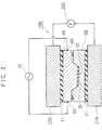
Fig. 2 is a section view of one embodiment of the resin molding apparatus of the present invention in use; -
Fig. 3 is a view showing a current application state in one embodiment of the resin molding apparatus of the present invention; -
Fig. 4 is a section view of another embodiment of the resin molding apparatus of the present invention in use; -
Fig. 5 is a view showing a current application state in another embodiment of the resin molding apparatus of the present invention; and -
Fig. 6 is a view showing another embodiment of the resin molding apparatus of the present invention. - In the figures illustrating each embodiment, parts or sites having similar actions are designated by the same number.
-
Fig. 1 is a schematic view showing a structure of aresin molding apparatus 100. Theresin molding apparatus 100 comprisesmetal molds current generator 70, as shown inFig. 1 . - The
metal molds insulating materials metal molds press 200. Thepress 200 comprises a fixedmember 210 and amovable member 220 which is opposed to the fixedmember 210 in vertical direction and is movable in vertical direction. Thepress 200 can forcibly descend themovable member 220 with a certain force towards the fixedmember 210. - The
metal mold 10 which is an upper mold among a pair ofmetal molds movable member 220 via theinsulating material 11. Themetal mold 20 which is a lower mold is arranged in the fixedmember 210 via theinsulating material 21. The upper andlower metal molds movable member 220 and fixedmember 210 respectively with theinsulating materials insulating materials metal molds materials metal molds - A pair of
metal molds molding part 40 to which aresin material 30 is provided to be molded. At least one metal mold (theupper metal mold 10 in this embodiment) among a pair ofmetal molds electrodes molding part 40. - The high frequency
current generator 70 is an apparatus generating high frequency current and is electrically connected to theelectrodes metal mold 10. The high frequencycurrent generator 70 can apply high frequency current between a pair ofelectrodes current generator 70 may be an apparatus which can adjust frequency and voltage of high frequency current. The high frequencycurrent generator 70 can be MK3, MK12, MK15, MK16A, MK18, MK19, MK20, MK22, MK22A, MK24, MK30, MK40, MK50-51, all of which are from NETUREN Co., Ltd. According to the present embodiment, the high frequencycurrent generator 70 is electrically connected between theelectrodes metal mold 10. Accordingly, an appropriate tank circuit, which is not shown in the figures, may be combined with the high frequencycurrent generator 70. - In the
resin molding apparatus 100, theresin material 30 is provided to themolding part 40 when a pair ofmetal molds Fig. 1 . Theresin material 30 may be, for example, a resin material comprising a thermoplastic resin and reinforcement fibers. Various resin materials may be used for theresin material 30, among which a resin material comprising reinforcement fibers oriented to a certain direction may preferably provided to themolding part 40 of the metal molds. A suitable example of theresin material 30 is a prepreg which is a fabric of reinforcement fiber with which a thermoplastic resin has been impregnated. Prepregs are reinforcement fibers with which a thermoplastic resin has been impregnated, so that the direction of the reinforcement fibers is preliminarily maintained. In addition, a thermoplastic resin can further impregnate with reinforcement fibers by re-heating upon molding in metal molds, so that the binding between the reinforcement fibers and the thermoplastic resin is enhanced. - Another suitable example of the
resin material 30 is, for example, a composite sheet proposed in Patent document 1 described above. In this composite sheet, continuous reinforcement fibers in each layer are oriented to a specific direction, so as to the directions of the continuous reinforcement fibers differ from each other in the layers laminated together. In addition, a thermoplastic resin non-woven fabric is laminated with the continuous reinforcement fibers and is combined therewith through stitching. In the present embodiment, this composite sheet is used as theresin material 30. InFig. 3 , thenumber 34 shows a laminated part of the continuous reinforcement fibers and thenumber 32 shows the thermoplastic resin non-woven fabric which is combined with the continuous reinforcement fibers through stitching. Thus, thiscomposite sheet 30 comprises thelaminated part 34 of the continuous reinforcement fibers and the thermoplasticresin non-woven fabric 32 laminated thereto. In this case, the thermoplasticresin non-woven fabric 32 may be arranged in themolding part 40 so as to face the (upper)metal mold 10, as shown inFig. 3 . - In the present embodiment, the
resin material 30 is provided to themolding part 40 and then a pair ofmetal molds Fig. 2 . High frequency current is then applied between a pair ofelectrodes metal mold 10 from the high frequencycurrent generator 70. High frequency current having a frequency of 10 kHz or more, for example, may be applied as high frequency current. High frequency current having a frequency of 100 kHz or more is more preferred to be applied as high frequency current. High frequency current having a frequency of 400 kHz or less is more preferred to be applied in order to obtain an appropriate output. - When high frequency current is applied between a pair of
electrodes metal mold 10, a surface part 16 (a layer having a certain depth from the surface) of themetal mold 10 allows the majority of high frequency current to flow according to the nature of high frequency current, as shown inFig. 3 . The depth δ (cm) of thesurface part 16 can be calculated theoretically from the formula (1), wherein."δ (cm)" is the depth from the surface of the layer which allows 73% of the total current to flow; "ρ (µΩ-cm)" is an intrinsic resistance of a metal used for themetal mold 10; f (Hz) is a frequency; and "µ" is a relative permeability. An amount of heat Q generated at thesurface part 16 can be calculated theoretically from the formula (2), wherein R (Ω) is a resistance in thesurface part 16; i (A) is an amount of current allowed to flow in thesurface part 16; and t (s) is the duration of application of high frequency current.
[E 1]
[E 2]
- As can be seen from the formula (1), when the frequency f of high frequency current applied between a pair of
electrodes metal mold 10 from the high frequencycurrent generator 70 is increased, δ is decreased and thesurface part 16 in which the majority of high frequency current is allowed to flow becomes shallow. Accordingly, more heat tends to be generated at the surface layer in themetal mold 10. - In the present embodiment, steel (SUS430 in this embodiment) is used for the
metal mold 10. The intrinsic resistance ρ (µΩ-cm) of themetal mold 10 is about 60 (µΩ-cm) to 70 (µΩ-cm). The relative permeability of themetal mold 10 is about 20. High frequency current having a frequency of 10 kHz or more is applied. Thus, the depth δ of thesurface part 16 in which about 63% of high frequency current is allowed to flow is about 0.09 cm or less. When the frequency of high frequency current is increased in this case, the surface part which the majority high frequency current is allowed to flow becomes shallow, so that more heat tends to be generated at the surface part of themetal mold 10. Due to such action of high frequency current, heat is generated at thesurface part 16 of themolding part 40 of themetal mold 10, as shown inFig. 3 . In this case, heat is generated rapidly at thesurface part 16 of themetal mold 10. The duration of application of high frequency current may be adjusted so that the thermoplastic resin in theresin material 30 is sufficiently melted to be molded. - Materials for metal molds generally used for thermoplastic resin materials are, for example, SKS, SKD, SKT or SKH used as tool steel, or SUS or SUH used as steel for special purposes. These materials have an intrinsic resistance ρ (µΩ-cm) from about 8 (µΩ-cm) to 120 (µΩ-cm) and a relative permeability from about 300 to 1. The high frequency
current generator 70 can apply high frequency current having a frequency of 10 kHz or more to metal molds. In this case, the frequency of high frequency current is extremely high compared to the intrinsic resistance ρ (µΩ-cm) or relative permeability of materials for metal molds, so that the depth δ of thesurface part 16 in which the majority of high frequency current is allowed to flow is mainly determined according to the frequency of high frequency current applied to metal molds, as can be seen from the above formula (1). When high frequency current having a frequency of 10 kHz or more is applied to metal molds made of usual materials for metal molds, the depth δ of thesurface part 16 in which the majority of high frequency current is allowed to flow can be about 0.009 cm or less. - According to the
resin molding apparatus 100, heat is generated mainly at thesurface part 16 of themolding part 40 of themetal mold 10, thereby theresin material 30 can be rapidly heated. Heat is generated at thesurface part 16 of themetal mold 10 and the inside of themetal mold 10 is merely heated due to heat transfer therefrom; thus themetal mold 10 as a whole is not heated to an extent that can melt resins. Thus, themetal mold 10 and theresin material 30 can be rapidly cooled down in a cooling step. A cooling configuration for themetal mold 10 is not shown in the figures; the metal mold can be cooled down by providing a flow passage in themetal mold 10 and allowing cooling water to flow through the flow passage, for example. - According to the present embodiment, the
surface part 16 of themetal mold 10 allows the majority of high frequency current to flow. The depth δ of thesurface part 16 is about 0.009 cm or less and heat is generated mainly at thesurface part 16 of themetal mold 10. The temperature of thesurface part 16 of themetal mold 10 may be a temperature required for molding a resin material. In this case, application of current to themetal mold 10 may be controlled in order to avoid the temperature of themetal mold 10 except for thesurface part 16 being too high. Accordingly, the temperature of themetal mold 10 except for thesurface part 16 can be avoided getting very hot. In this case, there is less necessity to consider temperature dependency of the stiffness of themetal mold 10, thereby deformation and damage to themetal mold 10 can be suppressed even when a high pressure is applied to themetal mold 10 upon molding. Accordingly, theresin molding apparatus 100 allows molding with high pressure at themetal mold 10, improving molding performances thereof. - According to the present embodiment, the
lower metal mold 20 does not have an electrode so that current is not applied directly thereto. Short circuit is not caused, however, when current is applied to thelower metal mold 20 through reinforcement fibers. Namely, themetal molds lower metal mold 20 through reinforcement fibers can flow back (return) to theupper metal mold 10 through reinforcement fibers in a similar manner, so that no potential difference is generated that causes short circuit between themetal molds resin molding apparatus 100 can appropriately heat theresin material 30 placed in themolding part 40 without causing short circuit when themetal molds - According to the
resin molding apparatus 100, high frequency current is applied to theelectrodes molding part 40 in theupper metal mold 10. In this case, reinforcement fibers in theresin material 30 may be fibers having no conductivity such as glass fibers, or fibers having high conductivity such as carbon fibers. When the reinforcement fibers are the fibers having high conductivity, high frequency current may also be applied to theresin material 30 through the fibers. The upper andlower metal molds materials resin material 30 through the reinforcement fibers because electricity returns to themetal mold 10 through the reinforcement fibers. In addition, when high frequency current is applied to the reinforcement fibers, heat can also be generated at the reinforcement fibers themselves. Moreover, the thermoplastic resin is heated in the vicinity of the reinforcement fibers, so that the viscosity of the resin is decreased and flowability of the resin is improved. Accordingly, the thermoplastic resin can more easily impregnate with the periphery of the reinforcement fibers. In addition, binding between the reinforcement fibers and the thermoplastic resin is improved, thereby improving mechanical properties of molded articles. - In a
resin molding apparatus 100A according to another embodiment,electrodes molding part 40 on each of a pair ofmetal molds Fig. 4 . The high frequencycurrent generator 70 in this case may be, as shown inFig. 4 , connected to theelectrodes molding part 40 in theupper metal mold 10 so as to be connected in parallel to theelectrodes molding part 40 in thelower metal mold 20. In this case, high frequency current is applied to the upper andlower metal molds Fig. 5 . As described above, the upper andlower metal molds current generator 70, so that no potential difference is generated that causes short circuit between the upper andlower metal molds resin molding apparatus 100A can appropriately heat theresin material 30 placed in themolding part 40 without causing short circuit. In this case, the upper andlower metal molds respective surface parts 16, so that theresin material 30 can be rapidly heated. - In a
resin molding apparatus 100B according to another embodiment, the surface of amolding part 40B inmetal molds Fig. 6 . Themetal molds Fig. 6 . In the example shown inFig, 6 , themolding part 40B forms a molding space circular in cross section jointly by the upper andlower metal molds resin molding apparatus 100B, the high frequencycurrent generator 70 is connected in parallel to twoelectrodes molding part 40B on each of a pair of themetal molds molding part 40B in themetal molds metal mold 40B of themetal molds molding part 40B is appropriately heated regardless of the shape of themolding part 40B. Accordingly, molded articles having atypical shapes can be molded. According to the present resin molding apparatus, a shape of molded articles, but not thickness thereof, is to be considered to design the molds because electrodes can be arranged with greater flexibility, so that the shape of molded articles also has greater flexibility. - As described above, the resin molding apparatus according to one embodiment of the present invention comprises a pair of
metal molds materials molding part 40 which is formed by a pair ofmetal molds resin material 30. At least onemetal mold 10 of a pair ofmetal molds electrodes molding part 40. The high frequencycurrent generator 70 is connected to twoelectrodes - According to such resin molding apparatus as above, because a pair of
metal molds materials metal molds metal molds resin material 30 is provided to themolding part 40. Short circuit does not occur when high frequency current is applied to themetal molds metal molds materials electrodes molding part 40 in themetal molds current generator 70 connected to theelectrodes - When high frequency current having a frequency of 10 kHz or more is applied according to such configuration, the surface of the
molding part 40 of themetal molds resin material 30. In thisresin molding apparatus 100, themetal molds metal molds - An embodiment of the resin molding apparatus and resin molding method according to the present invention has been described hereinabove; however, it should be understood that the resin molding apparatus and resin molding method according to the present invention is not limited to the embodiment described above.
- For example, in the above embodiment, the fiber-reinforced thermoplastic composite material is exemplified as the thermoplastic resin material. Such fiber-reinforced thermoplastic composite material includes, for example, a composite sheet of a thermoplastic resin non-woven fabric combined with continuous reinforcement fibers as disclosed in
JP 3947560 B - The thermoplastic resin material may include fiber-reinforced thermoplastic composite materials. Reinforcement fibers contained in the fiber-reinforced thermoplastic composite material exemplified above are carbon fibers and glass fibers. However, reinforcement fibers contained in the fiber-reinforced thermoplastic composite material are not limited thereto and may be fibers of plant origin, for example.
- The thermoplastic resin material is not limited to those described above and includes various thermoplastic resin materials. The thermoplastic resin materials suitable to be molded in the resin molding apparatus or by the resin molding method of the present invention include, but not limited to, for example, polyolefin-based resins such as polyethylenes, polypropylenes; polyamide-based resins typically including nylon 6, nylon 66, nylon 12 and nylon 46; polyester-based resins such as polyethylene terephthalate, polybutylene terephthalate; polyetherketone resins; polyphenylene sulfide resins; polyetherimide resins; polycarbonate resins and the like.
Claims (3)
- A resin molding apparatus (100) comprising:a press (200);a pair of metal molds (10, 20) respectively arranged in the press so as to be insulated from ground with insulating materials (11, 21), the pair of metal molds comprising a molding part;a pair of electrodes (50, 60) provided at two points flanking the molding part and arranged on both sides of the molding part in a first metal mold of the pair of metal molds; anda high frequency current generator (70) electrically connected between the pair of electrodes in the first metal mold and configured to generate heat at a surface part of the first metal mold by applying high frequency current having a frequency of 10 kHz or more between the pair of electrodes.
- The resin molding apparatus (100) according to claim 1, further comprising a second pair of electrodes (52, 62) provided at two points flanking the molding part and arranged on both sides of the molding part in a second metal mold of the pair of metal molds,
wherein the high frequency current generator is electrically connected between the second pair of electrodes in the second metal mold and configured to generate heat at a surface part of the second metal mold by applying high frequency current having a frequency of 10 kHz or more between the second pair of electrodes, and
wherein the pair of metal molds are electrically connected in parallel. - A resin molding method comprising the steps of:providing a thermoplastic resin material (30) to a molding part in a pair of metal molds (10, 20) respectively arranged so as to be insulated from ground with insulating materials (11, 21) andapplying high frequency current having a frequency of 10 kHz or more to a first metal mold of the pair of metal molds through a pair of electrodes (50, 60) provided at two points flanking the molding part and arranged on both sides of the molding part in a first metal mold of the pair of metal molds, thereby heating the pair of metal molds to mold the resin material provided to the molding part.
Applications Claiming Priority (2)
| Application Number | Priority Date | Filing Date | Title |
|---|---|---|---|
| JP2009060143 | 2009-03-12 | ||
| PCT/JP2010/054046 WO2010104129A1 (en) | 2009-03-12 | 2010-03-10 | Resin molding apparatus and resin molding method |
Publications (3)
| Publication Number | Publication Date |
|---|---|
| EP2407295A1 EP2407295A1 (en) | 2012-01-18 |
| EP2407295A4 EP2407295A4 (en) | 2016-12-28 |
| EP2407295B1 true EP2407295B1 (en) | 2019-06-12 |
Family
ID=42728417
Family Applications (1)
| Application Number | Title | Priority Date | Filing Date |
|---|---|---|---|
| EP10750882.2A Active EP2407295B1 (en) | 2009-03-12 | 2010-03-10 | Resin molding apparatus and resin molding method |
Country Status (5)
| Country | Link |
|---|---|
| US (1) | US9370884B2 (en) |
| EP (1) | EP2407295B1 (en) |
| JP (1) | JP5696992B2 (en) |
| KR (1) | KR101291263B1 (en) |
| WO (1) | WO2010104129A1 (en) |
Families Citing this family (27)
| Publication number | Priority date | Publication date | Assignee | Title |
|---|---|---|---|---|
| JP5107417B2 (en) * | 2010-12-24 | 2012-12-26 | 株式会社キャップ | Molding apparatus and molding method using the molding apparatus |
| TWI513565B (en) * | 2011-10-19 | 2015-12-21 | Kunshan yurong electronics co ltd | Mould with a heating device |
| CN103072222B (en) * | 2011-10-25 | 2015-06-24 | 昆山渝榕电子有限公司 | Die with heating device |
| CN104780241B (en) | 2012-02-24 | 2018-06-26 | 比亚迪股份有限公司 | A kind of handset shell |
| CN103286909B (en) | 2012-02-24 | 2015-09-30 | 比亚迪股份有限公司 | A kind of metal-resin integrated molding method and a kind of metal-resin composite |
| CN103286910B (en) | 2012-02-24 | 2015-09-30 | 比亚迪股份有限公司 | A kind of metal-resin integrated molding method and a kind of metal-resin composite |
| CN103286996B (en) | 2012-02-24 | 2015-03-25 | 比亚迪股份有限公司 | Preparation method of aluminum alloy-resin composite and aluminum alloy-resin composite prepared by using same |
| CN103287009B (en) * | 2012-02-24 | 2015-03-25 | 比亚迪股份有限公司 | Preparation method of aluminum alloy-resin composite and aluminum alloy-resin composite prepared by using same |
| CN103286908B (en) * | 2012-02-24 | 2015-09-30 | 比亚迪股份有限公司 | A kind of metal-resin integrated molding method and a kind of metal-resin composite |
| CN103286995B (en) | 2012-02-24 | 2015-06-24 | 比亚迪股份有限公司 | Preparation method of aluminum alloy-resin composite and aluminum alloy-resin composite prepared by using same |
| JP5956215B2 (en) * | 2012-03-29 | 2016-07-27 | 東邦テナックス株式会社 | Method for producing composite material molded article |
| WO2013178057A1 (en) | 2012-05-28 | 2013-12-05 | Shenzhen Byd Auto R&D Company Limited | Metal composite and method of preparing the same, metal-resin composite and method of preparing the same |
| TWI565105B (en) * | 2012-07-09 | 2017-01-01 | 山田尖端科技股份有限公司 | Resin molding device and resin molding method |
| US9801294B2 (en) * | 2012-11-29 | 2017-10-24 | Sunteng New Technology Co., Ltd. | Electronic device casing including coupling structure and method of manufacturing same |
| DE102013110530A1 (en) * | 2013-09-24 | 2015-03-26 | Tmd Friction Services Gmbh | Apparatus and method for the production of friction and brake linings |
| CN104746066B (en) | 2013-12-31 | 2017-07-04 | 比亚迪股份有限公司 | Bond material of a kind of metal and plastics and preparation method thereof and the bond material for preparing |
| CN104827608B (en) * | 2014-02-11 | 2017-11-07 | 刘忠男 | Mould with heating device |
| TWI625212B (en) * | 2014-02-11 | 2018-06-01 | 劉忠男 | Mould with heating device |
| JP6607556B2 (en) * | 2015-06-03 | 2019-11-20 | 三菱重工業株式会社 | Apparatus and method for curing resin composite material |
| US20170217056A1 (en) * | 2016-01-29 | 2017-08-03 | Dell Products L.P. | Carbon Fiber Information Handling System Housing and Process for Manufacture |
| KR101992870B1 (en) * | 2016-03-30 | 2019-06-25 | 반도 카가쿠 가부시키가이샤 | Belt manufacturing method, cylindrical mold and crosslinking apparatus used therefor |
| JP6354780B2 (en) * | 2016-03-31 | 2018-07-11 | マツダ株式会社 | Injection molding apparatus and injection molding method |
| TWI600521B (en) * | 2016-12-19 | 2017-10-01 | 中原大學 | Molding structure and heating method thereof |
| JP2019126923A (en) * | 2018-01-22 | 2019-08-01 | トヨタ自動車株式会社 | Molding die, molding apparatus, molding method, and manufacturing method of resin product |
| WO2019187071A1 (en) * | 2018-03-30 | 2019-10-03 | マツダ株式会社 | Injection molding device, injection molding method, and injection molding resin material |
| CN110900902B (en) * | 2019-12-09 | 2022-04-15 | 宋顺升 | Cold and hot integrative rubber and plastic steady type machine |
| US11628628B2 (en) * | 2020-05-26 | 2023-04-18 | Spirit Aerosystems, Inc. | Method of manufacturing simple curvature thermoplastic composite parts |
Family Cites Families (32)
| Publication number | Priority date | Publication date | Assignee | Title |
|---|---|---|---|---|
| US2979773A (en) * | 1959-08-26 | 1961-04-18 | Honeywell Regulator Co | Molding apparatus |
| JPS4614155B1 (en) * | 1967-06-13 | 1971-04-15 | ||
| FR1584599A (en) * | 1968-07-23 | 1969-12-26 | ||
| GB1278642A (en) * | 1969-06-04 | 1972-06-21 | Fibreglass Ltd | Improvements in and relating to the manufacture of bonded fibrous bodies |
| US4423191A (en) * | 1981-05-01 | 1983-12-27 | Massachusetts Institute Of Technology | High frequency electric field curing of polymeric composites |
| US4496131A (en) * | 1982-01-07 | 1985-01-29 | Yang Wen Jei | Apparatus for injection molding a foamed resin product having a smooth surface involving surface heating of the mold by applying high current low voltage electric power |
| DE3444525A1 (en) | 1984-12-06 | 1986-06-19 | Vdo Adolf Schindling Ag, 6000 Frankfurt | LIQUID CRYSTAL CELL |
| US5041247A (en) * | 1988-09-29 | 1991-08-20 | General Electric Company | Method and apparatus for blow molding parts with smooth surfaces |
| US5176839A (en) * | 1991-03-28 | 1993-01-05 | General Electric Company | Multilayered mold structure for hot surface molding in a short cycle time |
| US5227180A (en) * | 1991-10-07 | 1993-07-13 | Tisack Michael D | Apparatus for applying an electric field |
| US20040036201A1 (en) * | 2000-07-18 | 2004-02-26 | Princeton University | Methods and apparatus of field-induced pressure imprint lithography |
| JP3874511B2 (en) * | 1996-12-03 | 2007-01-31 | 日世株式会社 | Method for producing starch biodegradable molding |
| JP3982888B2 (en) * | 1996-12-16 | 2007-09-26 | 日世株式会社 | Method and apparatus for producing biodegradable molded product |
| US6612826B1 (en) * | 1997-10-15 | 2003-09-02 | Iap Research, Inc. | System for consolidating powders |
| US8852494B2 (en) * | 1999-10-08 | 2014-10-07 | Princeton University | Method and apparatus of electrical field assisted imprinting |
| FR2816237B1 (en) * | 2000-11-08 | 2003-09-19 | Roctool | MOLDS FOR PROCESSING PLASTICS AND COMPOSITES AND ASSOCIATED PROCESSING METHOD |
| DE10108570C2 (en) * | 2001-02-22 | 2003-05-28 | Laeis & Bucher Gmbh | Method and device for producing a shaped body |
| JP2003311799A (en) | 2002-04-22 | 2003-11-05 | Ricoh Co Ltd | Molding method and molding apparatus for plastic thin molded articles |
| US20040046281A1 (en) * | 2002-09-06 | 2004-03-11 | Byung Kim | Localized compression molding process for fabricating microstructures on thermoplastic substrates |
| JP4339003B2 (en) * | 2003-04-02 | 2009-10-07 | ジャパンスーパークォーツ株式会社 | Method for producing quartz glass crucible |
| GB0311494D0 (en) * | 2003-05-20 | 2003-06-25 | Stanelco Fibre Optics Ltd | Making foamed bodies |
| FR2867939B1 (en) * | 2004-03-18 | 2007-08-10 | Roctool | METHOD FOR HEATING MATERIALS TO PRODUCE OBJECTS AND DEVICE USING THE METHOD |
| TWI235628B (en) * | 2004-03-26 | 2005-07-01 | Ind Tech Res Inst | Monitoring system and method for imprint process |
| JP2006256078A (en) * | 2005-03-17 | 2006-09-28 | Ricoh Co Ltd | Press molding device, press molding method using this press molding device, and resin molded product formed by this press molding device |
| KR100973622B1 (en) | 2005-07-29 | 2010-08-02 | 학교법인 도시샤 | Method for forming fiber reinforced thermoplastic composite material and intermediates thereof, and composite sheet |
| TWI279304B (en) * | 2005-10-04 | 2007-04-21 | Chien Hui Chuan | The method and apparatus for heating mold by high frequency current |
| TW200821159A (en) * | 2006-11-07 | 2008-05-16 | Benq Corp | Paper kicker for exit roller and printer utilizing the same |
| US8021135B2 (en) * | 2007-06-08 | 2011-09-20 | Sabic Innovative Plastics Ip B.V. | Mold apparatus for forming polymer and method |
| US8375758B1 (en) * | 2007-09-13 | 2013-02-19 | The Boeing Company | Induction forming of metal components with slotted susceptors |
| US8372327B2 (en) * | 2007-09-13 | 2013-02-12 | The Boeing Company | Method for resin transfer molding composite parts |
| JP5107417B2 (en) * | 2010-12-24 | 2012-12-26 | 株式会社キャップ | Molding apparatus and molding method using the molding apparatus |
| TWI513565B (en) * | 2011-10-19 | 2015-12-21 | Kunshan yurong electronics co ltd | Mould with a heating device |
-
2010
- 2010-03-10 WO PCT/JP2010/054046 patent/WO2010104129A1/en not_active Ceased
- 2010-03-10 JP JP2011503848A patent/JP5696992B2/en not_active Expired - Fee Related
- 2010-03-10 EP EP10750882.2A patent/EP2407295B1/en active Active
- 2010-03-10 KR KR1020117021594A patent/KR101291263B1/en not_active Expired - Fee Related
- 2010-03-10 US US13/255,586 patent/US9370884B2/en not_active Expired - Fee Related
Non-Patent Citations (1)
| Title |
|---|
| None * |
Also Published As
| Publication number | Publication date |
|---|---|
| EP2407295A1 (en) | 2012-01-18 |
| WO2010104129A1 (en) | 2010-09-16 |
| US20120168990A1 (en) | 2012-07-05 |
| JPWO2010104129A1 (en) | 2012-09-13 |
| KR101291263B1 (en) | 2013-07-30 |
| KR20110127697A (en) | 2011-11-25 |
| US9370884B2 (en) | 2016-06-21 |
| JP5696992B2 (en) | 2015-04-08 |
| EP2407295A4 (en) | 2016-12-28 |
Similar Documents
| Publication | Publication Date | Title |
|---|---|---|
| US9370884B2 (en) | Resin molding apparatus and resin molding method | |
| US8097336B2 (en) | Methods and systems for manufacturing a structure having organized areas | |
| JP6333876B2 (en) | Apparatus and method for heating a mold or mold | |
| US20120315455A1 (en) | Preform and method for manufacturing the same | |
| EP0389798A2 (en) | Process for impregnation of glass fiber reinforcement with thermoplastic resins and for producing articles from the impregnated glass fiber | |
| CN114269548B (en) | Method and device for producing a component made of a fiber composite material | |
| EP2656992A1 (en) | Molding device and molding method by the molding device | |
| CN103459130A (en) | Device and method for compacting/consolidating a part made of a composite material having a thermoplastic matrix reinforced by continuous fibers, in particular fibers of natural origin | |
| EP2909012B1 (en) | Compliant layer for matched tool molding of uneven composite preforms | |
| RU2693148C1 (en) | Mold, molding device, molding method and method of producing polymer article | |
| Harrison et al. | Induction melt thermoforming of advanced multi-axial thermoplastic composite laminates | |
| CN106313526A (en) | Plastic and metal integrated hot press forming device and method | |
| JP6432750B2 (en) | Fiber reinforced composite material molding equipment | |
| JP6712430B1 (en) | Method for producing thermoplastic fiber-reinforced resin molded product | |
| JP7350255B2 (en) | Manufacturing method for foamed resin molded products | |
| US20050260398A1 (en) | Methods and systems for manufacturing a structure having organized areas | |
| KR102940409B1 (en) | Molding method using bio-composites | |
| JP7606714B1 (en) | Manufacturing apparatus and manufacturing method for fiber reinforced plastic molded products | |
| KR102082540B1 (en) | Production method and production device for preform | |
| US20240300192A1 (en) | Moulding apparatus | |
| EP4108431A1 (en) | A method for producing a thermoplastic composite component | |
| CN117507417A (en) | Apparatus and method for producing fiber-reinforced resin molded article | |
| JP2023156038A (en) | Molding method of mica component as well as press molding metal mold | |
| CN120985958A (en) | An apparatus and method for electrothermal curing of thermoplastic composite materials | |
| CN102765197A (en) | Hot-press forming method for thermoplastic resin matrix braided composite materials |
Legal Events
| Date | Code | Title | Description |
|---|---|---|---|
| PUAI | Public reference made under article 153(3) epc to a published international application that has entered the european phase |
Free format text: ORIGINAL CODE: 0009012 |
|
| 17P | Request for examination filed |
Effective date: 20111006 |
|
| AK | Designated contracting states |
Kind code of ref document: A1 Designated state(s): AT BE BG CH CY CZ DE DK EE ES FI FR GB GR HR HU IE IS IT LI LT LU LV MC MK MT NL NO PL PT RO SE SI SK SM TR |
|
| DAX | Request for extension of the european patent (deleted) | ||
| RA4 | Supplementary search report drawn up and despatched (corrected) |
Effective date: 20161129 |
|
| RIC1 | Information provided on ipc code assigned before grant |
Ipc: B29C 33/08 20060101ALI20161123BHEP Ipc: B29K 101/12 20060101ALI20161123BHEP Ipc: B29C 43/52 20060101AFI20161123BHEP Ipc: B29C 43/36 20060101ALI20161123BHEP |
|
| STAA | Information on the status of an ep patent application or granted ep patent |
Free format text: STATUS: EXAMINATION IS IN PROGRESS |
|
| 17Q | First examination report despatched |
Effective date: 20171117 |
|
| GRAP | Despatch of communication of intention to grant a patent |
Free format text: ORIGINAL CODE: EPIDOSNIGR1 |
|
| STAA | Information on the status of an ep patent application or granted ep patent |
Free format text: STATUS: GRANT OF PATENT IS INTENDED |
|
| INTG | Intention to grant announced |
Effective date: 20181206 |
|
| GRAS | Grant fee paid |
Free format text: ORIGINAL CODE: EPIDOSNIGR3 |
|
| GRAJ | Information related to disapproval of communication of intention to grant by the applicant or resumption of examination proceedings by the epo deleted |
Free format text: ORIGINAL CODE: EPIDOSDIGR1 |
|
| GRAL | Information related to payment of fee for publishing/printing deleted |
Free format text: ORIGINAL CODE: EPIDOSDIGR3 |
|
| STAA | Information on the status of an ep patent application or granted ep patent |
Free format text: STATUS: EXAMINATION IS IN PROGRESS |
|
| GRAR | Information related to intention to grant a patent recorded |
Free format text: ORIGINAL CODE: EPIDOSNIGR71 |
|
| STAA | Information on the status of an ep patent application or granted ep patent |
Free format text: STATUS: GRANT OF PATENT IS INTENDED |
|
| GRAA | (expected) grant |
Free format text: ORIGINAL CODE: 0009210 |
|
| STAA | Information on the status of an ep patent application or granted ep patent |
Free format text: STATUS: THE PATENT HAS BEEN GRANTED |
|
| INTC | Intention to grant announced (deleted) | ||
| AK | Designated contracting states |
Kind code of ref document: B1 Designated state(s): AT BE BG CH CY CZ DE DK EE ES FI FR GB GR HR HU IE IS IT LI LT LU LV MC MK MT NL NO PL PT RO SE SI SK SM TR |
|
| INTG | Intention to grant announced |
Effective date: 20190503 |
|
| REG | Reference to a national code |
Ref country code: GB Ref legal event code: FG4D |
|
| REG | Reference to a national code |
Ref country code: CH Ref legal event code: EP |
|
| REG | Reference to a national code |
Ref country code: AT Ref legal event code: REF Ref document number: 1142005 Country of ref document: AT Kind code of ref document: T Effective date: 20190615 |
|
| REG | Reference to a national code |
Ref country code: DE Ref legal event code: R096 Ref document number: 602010059393 Country of ref document: DE |
|
| REG | Reference to a national code |
Ref country code: IE Ref legal event code: FG4D |
|
| REG | Reference to a national code |
Ref country code: NL Ref legal event code: MP Effective date: 20190612 |
|
| REG | Reference to a national code |
Ref country code: LT Ref legal event code: MG4D |
|
| PG25 | Lapsed in a contracting state [announced via postgrant information from national office to epo] |
Ref country code: FI Free format text: LAPSE BECAUSE OF FAILURE TO SUBMIT A TRANSLATION OF THE DESCRIPTION OR TO PAY THE FEE WITHIN THE PRESCRIBED TIME-LIMIT Effective date: 20190612 Ref country code: LT Free format text: LAPSE BECAUSE OF FAILURE TO SUBMIT A TRANSLATION OF THE DESCRIPTION OR TO PAY THE FEE WITHIN THE PRESCRIBED TIME-LIMIT Effective date: 20190612 Ref country code: ES Free format text: LAPSE BECAUSE OF FAILURE TO SUBMIT A TRANSLATION OF THE DESCRIPTION OR TO PAY THE FEE WITHIN THE PRESCRIBED TIME-LIMIT Effective date: 20190612 Ref country code: HR Free format text: LAPSE BECAUSE OF FAILURE TO SUBMIT A TRANSLATION OF THE DESCRIPTION OR TO PAY THE FEE WITHIN THE PRESCRIBED TIME-LIMIT Effective date: 20190612 Ref country code: NO Free format text: LAPSE BECAUSE OF FAILURE TO SUBMIT A TRANSLATION OF THE DESCRIPTION OR TO PAY THE FEE WITHIN THE PRESCRIBED TIME-LIMIT Effective date: 20190912 Ref country code: SE Free format text: LAPSE BECAUSE OF FAILURE TO SUBMIT A TRANSLATION OF THE DESCRIPTION OR TO PAY THE FEE WITHIN THE PRESCRIBED TIME-LIMIT Effective date: 20190612 |
|
| PG25 | Lapsed in a contracting state [announced via postgrant information from national office to epo] |
Ref country code: LV Free format text: LAPSE BECAUSE OF FAILURE TO SUBMIT A TRANSLATION OF THE DESCRIPTION OR TO PAY THE FEE WITHIN THE PRESCRIBED TIME-LIMIT Effective date: 20190612 Ref country code: GR Free format text: LAPSE BECAUSE OF FAILURE TO SUBMIT A TRANSLATION OF THE DESCRIPTION OR TO PAY THE FEE WITHIN THE PRESCRIBED TIME-LIMIT Effective date: 20190913 Ref country code: BG Free format text: LAPSE BECAUSE OF FAILURE TO SUBMIT A TRANSLATION OF THE DESCRIPTION OR TO PAY THE FEE WITHIN THE PRESCRIBED TIME-LIMIT Effective date: 20190912 |
|
| REG | Reference to a national code |
Ref country code: AT Ref legal event code: MK05 Ref document number: 1142005 Country of ref document: AT Kind code of ref document: T Effective date: 20190612 |
|
| PG25 | Lapsed in a contracting state [announced via postgrant information from national office to epo] |
Ref country code: CZ Free format text: LAPSE BECAUSE OF FAILURE TO SUBMIT A TRANSLATION OF THE DESCRIPTION OR TO PAY THE FEE WITHIN THE PRESCRIBED TIME-LIMIT Effective date: 20190612 Ref country code: RO Free format text: LAPSE BECAUSE OF FAILURE TO SUBMIT A TRANSLATION OF THE DESCRIPTION OR TO PAY THE FEE WITHIN THE PRESCRIBED TIME-LIMIT Effective date: 20190612 Ref country code: SK Free format text: LAPSE BECAUSE OF FAILURE TO SUBMIT A TRANSLATION OF THE DESCRIPTION OR TO PAY THE FEE WITHIN THE PRESCRIBED TIME-LIMIT Effective date: 20190612 Ref country code: PT Free format text: LAPSE BECAUSE OF FAILURE TO SUBMIT A TRANSLATION OF THE DESCRIPTION OR TO PAY THE FEE WITHIN THE PRESCRIBED TIME-LIMIT Effective date: 20191014 Ref country code: AT Free format text: LAPSE BECAUSE OF FAILURE TO SUBMIT A TRANSLATION OF THE DESCRIPTION OR TO PAY THE FEE WITHIN THE PRESCRIBED TIME-LIMIT Effective date: 20190612 Ref country code: NL Free format text: LAPSE BECAUSE OF FAILURE TO SUBMIT A TRANSLATION OF THE DESCRIPTION OR TO PAY THE FEE WITHIN THE PRESCRIBED TIME-LIMIT Effective date: 20190612 Ref country code: EE Free format text: LAPSE BECAUSE OF FAILURE TO SUBMIT A TRANSLATION OF THE DESCRIPTION OR TO PAY THE FEE WITHIN THE PRESCRIBED TIME-LIMIT Effective date: 20190612 |
|
| PG25 | Lapsed in a contracting state [announced via postgrant information from national office to epo] |
Ref country code: IT Free format text: LAPSE BECAUSE OF FAILURE TO SUBMIT A TRANSLATION OF THE DESCRIPTION OR TO PAY THE FEE WITHIN THE PRESCRIBED TIME-LIMIT Effective date: 20190612 Ref country code: SM Free format text: LAPSE BECAUSE OF FAILURE TO SUBMIT A TRANSLATION OF THE DESCRIPTION OR TO PAY THE FEE WITHIN THE PRESCRIBED TIME-LIMIT Effective date: 20190612 Ref country code: IS Free format text: LAPSE BECAUSE OF FAILURE TO SUBMIT A TRANSLATION OF THE DESCRIPTION OR TO PAY THE FEE WITHIN THE PRESCRIBED TIME-LIMIT Effective date: 20191012 |
|
| REG | Reference to a national code |
Ref country code: DE Ref legal event code: R097 Ref document number: 602010059393 Country of ref document: DE |
|
| PG25 | Lapsed in a contracting state [announced via postgrant information from national office to epo] |
Ref country code: TR Free format text: LAPSE BECAUSE OF FAILURE TO SUBMIT A TRANSLATION OF THE DESCRIPTION OR TO PAY THE FEE WITHIN THE PRESCRIBED TIME-LIMIT Effective date: 20190612 |
|
| PLBE | No opposition filed within time limit |
Free format text: ORIGINAL CODE: 0009261 |
|
| STAA | Information on the status of an ep patent application or granted ep patent |
Free format text: STATUS: NO OPPOSITION FILED WITHIN TIME LIMIT |
|
| PG25 | Lapsed in a contracting state [announced via postgrant information from national office to epo] |
Ref country code: DK Free format text: LAPSE BECAUSE OF FAILURE TO SUBMIT A TRANSLATION OF THE DESCRIPTION OR TO PAY THE FEE WITHIN THE PRESCRIBED TIME-LIMIT Effective date: 20190612 Ref country code: PL Free format text: LAPSE BECAUSE OF FAILURE TO SUBMIT A TRANSLATION OF THE DESCRIPTION OR TO PAY THE FEE WITHIN THE PRESCRIBED TIME-LIMIT Effective date: 20190612 |
|
| 26N | No opposition filed |
Effective date: 20200313 |
|
| PG25 | Lapsed in a contracting state [announced via postgrant information from national office to epo] |
Ref country code: SI Free format text: LAPSE BECAUSE OF FAILURE TO SUBMIT A TRANSLATION OF THE DESCRIPTION OR TO PAY THE FEE WITHIN THE PRESCRIBED TIME-LIMIT Effective date: 20190612 Ref country code: IS Free format text: LAPSE BECAUSE OF FAILURE TO SUBMIT A TRANSLATION OF THE DESCRIPTION OR TO PAY THE FEE WITHIN THE PRESCRIBED TIME-LIMIT Effective date: 20200224 |
|
| PG2D | Information on lapse in contracting state deleted |
Ref country code: IS |
|
| PG25 | Lapsed in a contracting state [announced via postgrant information from national office to epo] |
Ref country code: IS Free format text: LAPSE BECAUSE OF FAILURE TO SUBMIT A TRANSLATION OF THE DESCRIPTION OR TO PAY THE FEE WITHIN THE PRESCRIBED TIME-LIMIT Effective date: 20191112 |
|
| PGFP | Annual fee paid to national office [announced via postgrant information from national office to epo] |
Ref country code: DE Payment date: 20200331 Year of fee payment: 11 |
|
| PG25 | Lapsed in a contracting state [announced via postgrant information from national office to epo] |
Ref country code: MC Free format text: LAPSE BECAUSE OF FAILURE TO SUBMIT A TRANSLATION OF THE DESCRIPTION OR TO PAY THE FEE WITHIN THE PRESCRIBED TIME-LIMIT Effective date: 20190612 |
|
| REG | Reference to a national code |
Ref country code: CH Ref legal event code: PL |
|
| REG | Reference to a national code |
Ref country code: BE Ref legal event code: MM Effective date: 20200331 |
|
| PG25 | Lapsed in a contracting state [announced via postgrant information from national office to epo] |
Ref country code: LU Free format text: LAPSE BECAUSE OF NON-PAYMENT OF DUE FEES Effective date: 20200310 |
|
| PG25 | Lapsed in a contracting state [announced via postgrant information from national office to epo] |
Ref country code: IE Free format text: LAPSE BECAUSE OF NON-PAYMENT OF DUE FEES Effective date: 20200310 Ref country code: LI Free format text: LAPSE BECAUSE OF NON-PAYMENT OF DUE FEES Effective date: 20200331 Ref country code: CH Free format text: LAPSE BECAUSE OF NON-PAYMENT OF DUE FEES Effective date: 20200331 Ref country code: FR Free format text: LAPSE BECAUSE OF NON-PAYMENT OF DUE FEES Effective date: 20200331 |
|
| PG25 | Lapsed in a contracting state [announced via postgrant information from national office to epo] |
Ref country code: BE Free format text: LAPSE BECAUSE OF NON-PAYMENT OF DUE FEES Effective date: 20200331 |
|
| GBPC | Gb: european patent ceased through non-payment of renewal fee |
Effective date: 20200310 |
|
| PG25 | Lapsed in a contracting state [announced via postgrant information from national office to epo] |
Ref country code: GB Free format text: LAPSE BECAUSE OF NON-PAYMENT OF DUE FEES Effective date: 20200310 |
|
| REG | Reference to a national code |
Ref country code: DE Ref legal event code: R119 Ref document number: 602010059393 Country of ref document: DE |
|
| PG25 | Lapsed in a contracting state [announced via postgrant information from national office to epo] |
Ref country code: DE Free format text: LAPSE BECAUSE OF NON-PAYMENT OF DUE FEES Effective date: 20211001 |
|
| PG25 | Lapsed in a contracting state [announced via postgrant information from national office to epo] |
Ref country code: MT Free format text: LAPSE BECAUSE OF FAILURE TO SUBMIT A TRANSLATION OF THE DESCRIPTION OR TO PAY THE FEE WITHIN THE PRESCRIBED TIME-LIMIT Effective date: 20190612 Ref country code: CY Free format text: LAPSE BECAUSE OF FAILURE TO SUBMIT A TRANSLATION OF THE DESCRIPTION OR TO PAY THE FEE WITHIN THE PRESCRIBED TIME-LIMIT Effective date: 20190612 |
|
| PG25 | Lapsed in a contracting state [announced via postgrant information from national office to epo] |
Ref country code: MK Free format text: LAPSE BECAUSE OF FAILURE TO SUBMIT A TRANSLATION OF THE DESCRIPTION OR TO PAY THE FEE WITHIN THE PRESCRIBED TIME-LIMIT Effective date: 20190612 |