EP2407136A1 - Tampon applicator - Google Patents
Tampon applicator Download PDFInfo
- Publication number
- EP2407136A1 EP2407136A1 EP10750917A EP10750917A EP2407136A1 EP 2407136 A1 EP2407136 A1 EP 2407136A1 EP 10750917 A EP10750917 A EP 10750917A EP 10750917 A EP10750917 A EP 10750917A EP 2407136 A1 EP2407136 A1 EP 2407136A1
- Authority
- EP
- European Patent Office
- Prior art keywords
- tube
- pushing
- end portion
- protrusion
- tampon
- Prior art date
- Legal status (The legal status is an assumption and is not a legal conclusion. Google has not performed a legal analysis and makes no representation as to the accuracy of the status listed.)
- Withdrawn
Links
Images


Classifications
-
- A—HUMAN NECESSITIES
- A61—MEDICAL OR VETERINARY SCIENCE; HYGIENE
- A61F—FILTERS IMPLANTABLE INTO BLOOD VESSELS; PROSTHESES; DEVICES PROVIDING PATENCY TO, OR PREVENTING COLLAPSING OF, TUBULAR STRUCTURES OF THE BODY, e.g. STENTS; ORTHOPAEDIC, NURSING OR CONTRACEPTIVE DEVICES; FOMENTATION; TREATMENT OR PROTECTION OF EYES OR EARS; BANDAGES, DRESSINGS OR ABSORBENT PADS; FIRST-AID KITS
- A61F13/00—Bandages or dressings; Absorbent pads
- A61F13/15—Absorbent pads, e.g. sanitary towels, swabs or tampons for external or internal application to the body; Supporting or fastening means therefor; Tampon applicators
- A61F13/20—Tampons, e.g. catamenial tampons; Accessories therefor
- A61F13/26—Means for inserting tampons, i.e. applicators
- A61F13/266—Insertion devices, e.g. rods or plungers, separate from the tampon
Definitions
- the present disclosure relates to a tampon applicator including an outer tube in which a tampon is ejectably placed and a pushing body which pushes the tampon in the outer tube toward an outside of the outer tube.
- a tampon applicator for a sanitary tampon is placed with a tampon configured to absorb body fluid such as menstrual fluid, and is used to insert the tampon into the vagina of a user.
- a tampon applicator widely adopts a sliding-type application system in which any one of a pair of hollow tube bodies moves slidingly with respect to the other.
- the tampon applicator includes a hollow outer tube in which the tampon is ejectably placed, and an inner tube (a pushing body) which pushes the tampon toward an outside of the outer tube by slidingly moving in the outer tube.
- the outer tube has a main body portion in which the tampon is placed, an outer-tube tip end portion which is inserted into the vagina of a user, and an outer-tube rear end portion which is positioned opposite to the outer-tube tip end portion.
- the outer-tube tip end portion has an opening from which the tampon is ejected.
- the inner tube has an inner-tube tip end portion (a pushing tip end portion) which pushes the tampon toward the outside of the outer tube and an inner tube rear end (a pushing rear end portion) which is positioned opposite to the inner-tube tip end portion and is pushed by a user toward the outer-tube tip end portion.
- the tampon applicator is inserted from the outer-tube tip end portion into the vagina of the user.
- the user pushes the inner tube rear end toward the outer-tube tip end portion. With this movement, the tampon placed in the outer tube is pushed by the inner tube (the inner-tube tip end portion) so that the tampon is inserted into the vagina of the user.
- the above-described conventional tampon applicator has the following problem. That is, it is extremely hard to see from an outside of the tampon applicator whether the tampon is placed inside the tampon applicator. This causes the problem that, although a tampon is not placed inside the tampon applicator, a user accidentally uses the sanitary tampon in which the tampon is not placed in the tampon applicator.
- an object of the invention is to provide a tampon applicator capable of securely preventing a user from accidentally using a sanitary tampon in which a tampon is not placed in a tampon applicator.
- a tampon applicator e.g., a tampon applicator 100
- a tampon applicator including: an outer tube (outer tube 110) in which a tampon (tampon 10) is ejectably placed; and a pushing body (inner tube 120) which pushes the tampon toward the outside of the outer tube by slidingly moving in the outer tube.
- the outer tube includes: an outer-tube tip end portion (outer-tube tip end portion 111), on which an opening (opening 111A) to eject the tampon therefrom is formed, and which is inserted into a vagina of a user; and an outer-tube rear end portion (outer-tube rear end portion 112) positioned opposite to the outer-tube tip end portion.
- the pushing body includes: a pushing tip end portion (pushing tip end portion 121) which pushes the tampon toward the outside of the outer tube; a pushing rear end portion (pushing rear end portion 122) positioned opposite to the pushing tip end portion; and a protrusion (e.g., a protrusion 200) provided in the vicinity of the pushing rear end portion and protruding from the outer circumference of the pushing body.
- the outer tube is provided with a locking portion (locking portion 213) which locks the protrusion when the pushing body is inserted in the outer tube.
- the protrusion is capable of passing by the locking portion from the outer-tube rear end portion side to the outer-tube tip end portion side.
- the locking portion locks the protrusion to prevent the pushing body from returning to the outer-tube rear end portion side of the locking portion.
- a tampon applicator according to the invention is described below by referring to the drawings. Specifically, first, second, and other embodiments are described.
- Fig. 1 is a perspective view showing the sanitary tampon 1 according to the first embodiment.
- Fig. 2 is a side view (seen from the direction shown by arrow A in Fig. 1 ) showing the sanitary tampon 1 according to the first embodiment.
- the sanitary tampon 1 has a tampon 10 (an absorber) which absorbs body fluid such as menstrual fluid and a tampon applicator 100 for inserting the tampon 10 into a vagina of a user.
- a tampon 10 an absorber
- body fluid such as menstrual fluid
- a tampon applicator 100 for inserting the tampon 10 into a vagina of a user.
- the tampon 10 is placed, in a compressed state, in an outer tube 110, to be described later, of the tampon applicator 100.
- the tampon 10 includes an absorber (not shown) having absorbable fibers and a covering material (not shown) covering the absorber.
- a cord-like body 11 is connected with the tampon 10 and is drawn to eject the tampon 10 from the vagina of the user.
- Fig. 3 is a partially-exploded side view of the outer tube 110 according to the first embodiment.
- Fig. 4 (a) is a side view of an inner tube 120 according to the first embodiment.
- Fig. 4 (b) is a front view (a cross-sectional view taken along the A-A line in Fig. 4 (a) ) of the inner tube 120 according to the first embodiment.
- the tampon applicator 100 includes a hollow outer tube 110 in which the tampon 10 is ejectably placed, and a hollow inner tube 120 (pushing body) into which the above-described cord-like body 11 is inserted and which pushes the tampon 10 toward the outside of the outer tube 110 by slidingly moving in the outer tube 110 .
- outer tube 110 and the inner tube 120 are formed of the same material such as, for example, polyethylene (PE), polyethylene terephthalate (PET), polypropylene (PP), a laminated nonwoven fiber, or paper.
- PE polyethylene
- PET polyethylene terephthalate
- PP polypropylene
- the outer tube 110 has an outer-tube tip end portion 111 and an outer-tube rear end portion 112.
- the outer-tube tip end portion 111 has an opening 111A to eject the tampon 10 therefrom, and is inserted into the vagina of the user.
- the opening 111A gradually tapers toward the outer-tube tip end portion 111 and opens by being pushed by the tampon 10 from the inside of the outer tube 110.
- the outer-tube rear end portion 112 is positioned opposite to the outer-tube tip end portion 111, and the inner tube 120 is always inserted thereinto.
- the outer tube 110 includes a main body portion 211 and a grip portion 212 (a small diameter portion).
- the main body portion 211 has a predetermined diameter.
- the diameter of the main body portion 211 is constant.
- the grip portion 212 is provided closer to the outer-tube rear end portion 112 than the main body portion 211.
- the diameter of the grip portion 212 is smaller than that of the main body portion 211, and is constant.
- the main body portion 211 and the grip portion 212 are continuous at a substantially right angle when seen from the side of the outer tube 110.
- the outer tube 110 has a locking portion 213 which locks a later-described protrusion 200 formed in the outer tube 120 when the inner tube 120 is inserted in the outer tube 110.
- the locking portion 213 locks the protrusion 200 to prevent the inner tube 120 from returning to the outer-tube rear end portion 112 side of the locking portion 213.
- the locking portion 213 is provided between the main body portion 211 and the grip portion 212. In other words, the locking portion 213 is in a boundary where the main body portion 211 and the grip portion 212 are continuous.
- the inner tube 120 has substantially the same diameter as the grip portion 212.
- the "substantially the same" diameter includes a diameter slightly smaller than that of the grip portion 212.
- the inner tube 120 has a pushing tip end portion 121 and a pushing rear end portion 122.
- the pushing tip end portion 121 pushes the tampon 10 toward the outside of the outer tube 110.
- the pushing rear end portion 122 is positioned opposite to the pushing tip end portion 121 and is pushed toward the outer-tube tip end portion 111 by the user.
- the inner tube 120 has a tip-end-side projection 131, a rear-end-side projection 132, and the protrusion 200.
- the tip-end-side projection 131 is provided closer to the pushing tip end portion 121 than the protrusion 200 is and projects from the outer circumference of the inner tube 120 outward beyond the diameter of the grip portion 212. It is preferable that the tip-end-side projection 131 be formed within 30 mm towards the pushing tip end portion 122 from the pushing tip end portion 121. It is also preferable that a protruding height H1 of the tip-end-side projection 131 from the outer circumference of the inner tube 120 be larger than a protruding height H2 of the protrusion 200 from the outer circumference of the inner tube 120.
- the rear-end-side projection 132 is provided closer to the pushing rear end portion side 122 than the protrusion 200 is and projects from the outer circumference of the inner tube 120 outward beyond the diameter of the grip portion 212. It is preferable that the rear-end-side projection 132 be formed within 30 mm towards the pushing tip end portion 121 from the pushing rear end portion 122. It is also preferable that a protruding height H3 of the rear-end-side projection 132 from the outer circumference of the inner tube 120 be larger than the protruding height H2 of the protrusion 200 from the outer circumference of the inner tube 120.
- the protrusion 200 is provided in the vicinity of the pushing rear end portion 122 and projects from the outer circumference of the inner tube 120.
- the protrusion 200 includes two protrusions 200 placed facing each other across an axis of the inner tube 120.
- a length L1 from the protrusion 200 to the pushing rear end portion 122 in a longitudinal direction of the inner tube 120 is larger than a length L2 of the grip portion 212 in the longitudinal direction of the outer tube 110.
- a length L3 from the protrusion 200 to the pushing tip end portion 121 in the longitudinal direction of the inner tube 120 is smaller than a length L4 of the main body portion 211 in the longitudinal direction of the outer tube 110.
- Fig. 5 (a) is a side view of the protrusion 200 according to the first embodiment.
- Fig. 5 (b) is a top view of the protrusion 200 according to the first embodiment.
- the protrusion 200 along with the sliding movement of the inner tube 120 in the outer tube 110, can pass by the locking portion 213 from the outer-tube rear end portion 112 side to the outer-tube tip end portion 111 side.
- the protrusion 200 has a substantially trapezoidal shape when seen from the side thereof.
- the protrusion 200 includes a front face 201 (a front portion), a rear face 202 (a rear portion), a top face 203, and a pair of side faces 204.
- the front face 201 is positioned facing toward the pushing tip end portion 121.
- the front face 201 is inclined with respect to the outer circumference of the inner tube 120, and extends toward the pushing rear end portion 122 while gradually rising outward from the outer circumference of the inner tube 120. It is preferable that an angle ⁇ , which is an inner angle of the front face 201 and the outer circumference of the inner tube 120 be 10° to 90°, or, more preferably, 30° to 60°.
- the rear face 202 is positioned opposite to the front face 201 and closer to the pushing rear end portion 122 than the front face 201.
- the rear face 202 is substantially perpendicular to the outer circumference of the inner tube 120. It is preferable that an angle ⁇ , which is an outer angle of the rear face 202 and the outer circumference of the inner tube 120, be 30° to 120°, or, more preferably, 90° to 120°.
- the top face 203 is continuous with the front face 201 and the rear face 202, and is substantially parallel with the outer circumference of the inner tube 120. It is preferable that an angular portion 205 at which the top face 203 and the front face 201 are continuous be formed in an arcuate shape (an R-letter shape).
- the paired side faces 204 are continuous with the front face 201 and the rear face 202, and face each other substantially in parallel.
- the protrusion 200 can pass by the locking portion 213 from the outer-tube rear end portion 112 side to the outer-tube tip end portion 111 side.
- the protrusion 200 passes the grip portion 212 without being caught on the grip portion 212 and moves to the main body portion 211.
- the protrusion 200 does not become an obstacle for the inner tube 120.
- the locking portion 213 locks the protrusion 200 to prevent the inner tube 120 from returning to the outer-tube rear end portion 122 side of the locking portion 213.
- the locking portion 213 locks the protrusion 200, preventing the inner tube 120 from returning to the state before the sanitary tampon 1 is used.
- the locking portion 213 is provided between the main body portion 211 and the grip portion 212.
- the locking portion 213 is in a boundary where the main body portion 211 and the grip portion 212 are continuous.
- the grip portion 212 has a smaller diameter than the main body portion 211 so that the user can easily handle the sanitary tampon 1. For this reason, there is no need to include the locking portion 213 in the outer tube 110. Accordingly, the manufacturing cost of the sanitary tampon 1 can be reduced.
- the front face 201 is inclined with respect to the outer circumference of the inner tube 120, and extends toward the pushing rear end portion 122 while gradually rising outward from the outer circumference of the inner tube 120. It is preferable that the angle ⁇ between the front face 201 and the outer circumference of the inner tube 120 be 10° to 90°.
- This structure allows the protrusion 200 to easily pass inside the grip portion 212. Thus, the protrusion 200 can be prevented from being caught on the grip portion 212 when the inner tube 120 pushes the tampon 10 toward the outside of the outer tube 110.
- the protrusion 200 cannot have a sufficient height, causing the protrusion 200 having passed the locking portion 213 to easily return toward the outer-tube rear end portion 112. Furthermore, when it is attempted to give the protrusion 200 a height needed for the locking portion 213 to lock the protrusion 200, the length of the protrusion 200 in the longitudinal direction of the inner tube 120 becomes longer. As a result, it becomes difficult for the protrusion 200 to pass inside the grip portion 212. On the other hand, if the angle ⁇ is larger than 90°, it becomes difficult for the protrusion 200 to get into the grip portion 212.
- the rear face 202 is substantially perpendicular to the outer circumference of the inner tube 120. It is preferable that the angle ⁇ between the rear face 202 and the outer circumference of the inner tube 120 be 30° to 120°.
- the protrusion 200 can pass the grip portion 212, and the locking portion 213 can securely lock the rear face 202. Accordingly, it is difficult for the inner tube 120 to return to the state before the sanitary tampon 1 is used, after the locking portion 213 locks the protrusion 200.
- the angle ⁇ is smaller than 30°, when it is attempted to give the protrusion 200 a height needed for the locking portion 213 to lock the protrusion 200, the length of the protrusion 200 in the longitudinal direction of the inner tube 120 becomes longer. As a result, it becomes difficult for the protrusion 200 to pass inside the grip portion 212. On the other hand, if the inclination angle ⁇ is larger than 120°, it becomes easy for the inner tube 120 to return to the state before the sanitary tampon 1 is used.
- the length L1 from the protrusion 200 to the pushing rear end portion 122 in the longitudinal direction of the inner tube 120 is larger than the length L2 of the grip portion 212 in the longitudinal direction of the outer tube 110. If the length L1 is smaller than the length L2, the protrusion 200 cannot pass the grip portion 212, which prevents the protrusion 200 from reaching the locking portion 213. As a result, it becomes easy for the inner tube 120 to return to the state before the sanitary tampon 1 is used.
- the length L3 from the protrusion 200 to the pushing tip end portion 121 in the longitudinal direction of the inner tube 120 is smaller than the length L4 of the main body portion 211 in the longitudinal direction of the outer tube 110. If the length L3 is larger than the length L4, the inner tube 120 (the pushing tip end portion 121) comes out from the outer tube 110 when the protrusion 200 passes by the locking portion 213 from the outer-tube rear end portion 112 side to the outer-tube tip end portion 111 side.
- the inner tube 120 has the tip-end-side projection 131 which is provided closer to the pushing tip end portion 121 than the protrusion 200 is.
- the tip-end-side projection 131 comes in contact with the outer-tube tip end portion 111 (the opening 111A) after the protrusion 200 passes by the locking portion 213 from the outer-tube rear end portion 112 side to the outer-tube tip end portion 111 side. This further allows prevention of the inner tube 120 (the pushing tip end portion 121) from coming out from the outer tube 110.
- the tip-end-side projection 131 be formed within 30 mm towards the pushing rear end portion 122 from the pushing tip end portion 121. If the tip-end-side projection 131 is formed in a position apart from the pushing tip end portion 121 by more than 30 mm, the inner tube 120 (the pushing tip end portion 121) comes out from the outer tube 110 in some cases.
- the inner tube 120 has the rear-end-side projection 132 which is provided closer to the pushing rear end portion 122 than the protrusion 200.
- the rear-end-side projection 132 be formed within 30 mm towards the pushing tip end portion 121 from the pushing rear end portion 122. If the rear-end-side projection 132 is formed in a position apart from the pushing rear end portion 122 by more than 30 mm, the inner tube 120 cannot completely push the tampon 10 toward the outside of the outer tube 110 in some cases.
- the angular portion 205 at which the top face 203 and the front face 201 are continuous be formed in an arcuate shape (an R-letter shape).
- the protrusion 200 according to the first embodiment has a substantially trapezoidal shape when seen from the side thereof.
- the shape of the protrusion 200 may be changed as follows. It should be noted that same reference signs are given to denote portions same as those of the protrusion 200 according to the first embodiment, and that the different portions are mainly described.
- FIG. 6 (a) is a side view showing the protrusion 210 according to Variation 1.
- Fig. 6 (b) is a front view showing an inner tube 120 according to Variation 1.
- the protrusion 210 has a substantially triangular shape when seen from the side thereof and in an axial direction of the inner tube 120.
- a portion in which the protrusion 210 protrudes most is formed in an arcuate shape (an R-letter shape).
- the portion where the protrusion 210 protrudes most does not necessarily have to have an arcuate shape, and may be pointed, for example.
- the protrusion 210 does not necessarily have to have a substantially triangular shape when seen from the side thereof and in the axial direction of the inner tube 120.
- the protrusion 210 may have a substantially triangular shape when seen either from the side thereof or in the axial direction of the inner tube 120.
- FIG. 7(a) is a side view showing the protrusion 220 according to Variation 2.
- Fig. 7 (b) is a front view showing an inner tube 120 according to Variation 2.
- the protrusion 220 has a semi-circular shape when seen from the side thereof. It should be noted that the protrusion 220 does not necessarily have to have a semi-circular shape, and may have a semi-spherical shape or semi-elliptic shape, for example.
- FIG. 8 (a) is a side view showing the protrusion 230 according to Variation 3.
- Fig. 8 (b) is a front view showing an inner tube 120 according to Variation 3.
- the protrusion 230 has a plate shape including with respect to the outer circumference of the inner tube 120 extending toward the pushing rear end portion 122 while gradually rising outward from the outer circumference of the inner tube 120.
- the thickness of the protrusion 230 is substantially constant. It should be noted that the protrusion 230 does not necessarily have to have a constant thickness, and may have an uneven thickness.
- the protrusion 230 may be provided on the outer circumference of the inner tube 120 as a separate body. Alternatively, the protrusion 230 may be formed by lifting a cutout formed in the inner tube 120.
- the protrusion 200 according to the first embodiment includes two protrusions 200 which are provided facing each other across the axis of the inner tube 120.
- the layout of the protrusions 200 may be modified as follows. It should be noted that the same reference sings are given to denote portions same as those of the protrusion 200 according to the first embodiment, and that different portions are mainly described.
- Fig. 9 (a) is a side view showing one of the protrusions 240 according to Modification 1.
- Fig. 9 (b) is a front view showing an inner tube 120 according to Modification 1.
- the protrusions 240 include four protrusions 240A to 240D which are provided facing each other across the axis of the inner tube 120. It should be noted that the number of the protrusions 240A to 240D does not necessarily have to be four, but may be four or more and be placed so as to be continuous over the entire region of the outer circumference of the inner tube 120.
- Fig. 10 (a) is a side view showing part of an inner tube 120 according to Modification 2.
- Fig. 10 (b) is a front view showing the inner tube 120 according to Modification 2.
- the protrusions 250 include four protrusions 250A to 250D.
- the protrusions 250A and 250B are provided in the same line, and the protrusions 250C and 250D are provided in the same line.
- each of the protrusions 250A and 250C positioned closer to a pushing tip end portion 121 has a height H10 which is preferably smaller than a height H20 of each of the protrusions 250B and 250D. This is because such structure allows the protrusion 200 to easily get into the inside of the grip portion 212 and the inner tube 120 to be prevented from returning to the state before the sanitary tampon 1 is used.
- Fig. 11 (a) is a side view showing part of an inner tube 120 according to Modification 3.
- Fig. 11 (b) is a front view showing the inner tube according to Modification 3.
- the protrusions 260 include eight protrusions 260A to 260H. Each of the protrusions 260A to 260H is displaced from the adjacent protrusions in the longitudinal direction of the inner tube 120.
- a tampon applicator 100A according to a second embodiment of the invention is described by referring to the drawings. It should be noted that the same reference signs are given to denote the same portions as those of the above-described tampon applicator 100 according to the first embodiment.
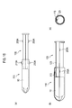
- Fig. 12 is a perspective view showing a sanitary tampon applicator 100A according to the second embodiment.
- Fig. 13 is a side view (seen from the direction show by arrow A) showing a sanitary tampon 1A according to the second embodiment.
- Fig. 14 is a partially-exploded side view of an outer tube 110 according to the second embodiment.
- Fig. 15 (a) is a side view of an inner tube 120 according to the second embodiment.
- Fig. 15 (b) is a front view (a cross-sectional view taken along the A-A line in Fig. 15 (a) ) showing the inner tube 120 according to the second embodiment.
- the outer tube 110 includes the main body portion 211 and the grip portion 212.
- the outer tube 110 has a constant diameter.
- the inner tube 120 has substantially the same diameter as the outer tube 110.
- the inner tube 120 is provided with a protrusion 200A formed continuously with an outer circumference of the inner tube 120.
- the outer tube 110 is provided with a locking portion 213A formed continuously with an outer circumference of the outer tube 110.
- the locking portion 213A projects in an inner circumferential surface of the outer tube 110 outward in a radial direction of the outer tube 110.
- the protrusion 200A has the same shape as, or a shape smaller than, the locking portion 213A. It should be noted that various shapes described in the first embodiment (Variations 1 to 3 and Modifications 1 to 3) are applicable to the protrusion 200A and the locking portion 213A.
- the protrusion 200A does not necessarily have to be formed continuously with the outer circumference of the inner tube 120.
- the protrusion 200A may be at least one or more protrusions. In this case, it is preferable to consider that positions of the protrusion 200A and the locking portion 213A are displaced with each other in some cases.
- the locking portion 213A may be formed continuously with the outer circumference of the outer tube 110.
- the inner tube 120 may have a rail 123 recessed in an inner circumference thereof, and the outer tube 110 may have a rail 113 protruding from an inner circumference thereof.
- the rail 123 may be formed in a projection shape, in which case the rail 113 is formed in a recess shape.
- the locking portion 213A locks the protrusion 200A.
- the inner tube 120 does not return to the state before the sanitary tampon 1A is used. This surely prevents the user from accidentally using the sanitary tampon 1A in which the tampon 10 is not placed in the tampon applicator 100A.
- the embodiments of the invention can be modified as follows.
- the sanitary tampon 1 is not limited to the sanitary tampons 1 described in the first and second embodiments, but is applicable for example to a shape of the sanitary tampon 1, i.e., shapes of an outer tube 110 and an inner tube 120, as shown in Fig. 17 , .
- a locking portion 213A formed in the outer tube 110 protrudes in an inner circumferential surface of the outer tube 110 outward in the radial direction of the outer tube 110.
- the protrusion 200A has the same shape as, or a shape smaller than, the locking portion 213A.
- outer tube 110 and the inner tube 120 have been described as being formed of the same material.
- the present invention is not limited to such case, and the outer tube 110 may be formed of a material softer than the inner tube 120 so that the protrusion 200 can easily pass inside the grip portion 212.
- the thicknesses of the outer tube 110 and the inner tube 120 are not particularly limited.
- the thickness of the outer tube 110 may be smaller than the thickness of the inner tube 120 so that the protrusion 200 can easily pass inside the grip portion 212.
- the inner tube 120 has been described as being a hollow tube.
- the inner tube 120 is not limited to this, and may of course have a different shape, such as a prismatic shape, as long as it can push the tampon 10 to the outside of the outer tube 110 and as long as a cord-like body 11 can be inserted therein.
- the shape, structure, number, and layout of the protrusion 200 are not particularly limited and may be any ones other than those described in the above-described embodiments and may be selectable appropriately.
- the present invention can provide a tampon applicator capable of securely preventing a user from accidentally using a sanitary tampon in which a tampon is not placed in the tampon applicator, it is useful in manufacturing of the tampon applicator.
Abstract
Description
- The present disclosure relates to a tampon applicator including an outer tube in which a tampon is ejectably placed and a pushing body which pushes the tampon in the outer tube toward an outside of the outer tube.
- A tampon applicator for a sanitary tampon is placed with a tampon configured to absorb body fluid such as menstrual fluid, and is used to insert the tampon into the vagina of a user. In general, a tampon applicator widely adopts a sliding-type application system in which any one of a pair of hollow tube bodies moves slidingly with respect to the other.
- Specifically, the tampon applicator includes a hollow outer tube in which the tampon is ejectably placed, and an inner tube (a pushing body) which pushes the tampon toward an outside of the outer tube by slidingly moving in the outer tube.
- The outer tube has a main body portion in which the tampon is placed, an outer-tube tip end portion which is inserted into the vagina of a user, and an outer-tube rear end portion which is positioned opposite to the outer-tube tip end portion. The outer-tube tip end portion has an opening from which the tampon is ejected.
- The inner tube has an inner-tube tip end portion (a pushing tip end portion) which pushes the tampon toward the outside of the outer tube and an inner tube rear end (a pushing rear end portion) which is positioned opposite to the inner-tube tip end portion and is pushed by a user toward the outer-tube tip end portion.
- The tampon applicator is inserted from the outer-tube tip end portion into the vagina of the user. The user pushes the inner tube rear end toward the outer-tube tip end portion. With this movement, the tampon placed in the outer tube is pushed by the inner tube (the inner-tube tip end portion) so that the tampon is inserted into the vagina of the user.
- Japanese Patent Application Publication No.
Hei. 3-38854 - In some situations such as when a sanitary container or the like is not near a user of a sanitary tampon, the user has to bring back a tampon applicator having no tampon after use.
- In such a case, the above-described conventional tampon applicator has the following problem. That is, it is extremely hard to see from an outside of the tampon applicator whether the tampon is placed inside the tampon applicator. This causes the problem that, although a tampon is not placed inside the tampon applicator, a user accidentally uses the sanitary tampon in which the tampon is not placed in the tampon applicator.
- Accordingly, an object of the invention is to provide a tampon applicator capable of securely preventing a user from accidentally using a sanitary tampon in which a tampon is not placed in a tampon applicator.
- To solve the above problem, the present invention has the following aspect. The aspect of the present invention is summarized as a tampon applicator (e.g., a tampon applicator 100) including: an outer tube (outer tube 110) in which a tampon (tampon 10) is ejectably placed; and a pushing body (inner tube 120) which pushes the tampon toward the outside of the outer tube by slidingly moving in the outer tube. In the tampon applicator, the outer tube includes: an outer-tube tip end portion (outer-tube tip end portion 111), on which an opening (opening 111A) to eject the tampon therefrom is formed, and which is inserted into a vagina of a user; and an outer-tube rear end portion (outer-tube rear end portion 112) positioned opposite to the outer-tube tip end portion. The pushing body includes: a pushing tip end portion (pushing tip end portion 121) which pushes the tampon toward the outside of the outer tube; a pushing rear end portion (pushing rear end portion 122) positioned opposite to the pushing tip end portion; and a protrusion (e.g., a protrusion 200) provided in the vicinity of the pushing rear end portion and protruding from the outer circumference of the pushing body. The outer tube is provided with a locking portion (locking portion 213) which locks the protrusion when the pushing body is inserted in the outer tube. Along with a sliding movement of the pushing body in the outer tube, the protrusion is capable of passing by the locking portion from the outer-tube rear end portion side to the outer-tube tip end portion side. When the protrusion is positioned on the outer-tube tip end portion side of the locking portion, the locking portion locks the protrusion to prevent the pushing body from returning to the outer-tube rear end portion side of the locking portion.
-
- [
Fig. 1] Fig. 1 is a perspective view of a sanitary tampon 1 according to a first embodiment; - [
Fig. 2] Fig. 2 is a side view of the sanitary tampon 1 according to the first embodiment; - [
Fig. 3] Fig. 3 is a partially-exploded side view of anouter tube 110 according to the first embodiment; - [
Fig. 4] Figs. 4 (a) and 4 (b) are views showing aninner tube 120 according to the first embodiment; - [
Fig. 5] Figs. 5 (a) and 5 (b) are views showing aprotrusion 200 according to the first embodiment; - [
Fig. 6] Figs. 6 (a) and 6 (b) are views showing aprotrusion 210 according to Variation 1; - [
Fig. 7] Figs. 7 (a) and 7 (b) are views showing aprotrusion 220 according to Variation 2; - [
Fig. 8] Figs. 8 (a) and 8 (b) are views showing aprotrusion 230 according to Variation 3; - [
Fig. 9] Figs. 9 (a) and 9 (b) are views showing aprotrusion 240 according to Modification 1; - [
Fig. 10] Figs. 10 (a) and 10 (b) are views showing aprotrusion 250 according to Modification 2; - [
Fig. 11] Figs. 11 (a) and 11 (b) are views showing a protrusion 260 according to Modification 3; - [
Fig. 12] Fig. 12 is a perspective view (Part 1) of a sanitary tampon 1A according to a second embodiment; - [
Fig. 13] Fig. 13 is a side view of the sanitary tampon 1A according to the second embodiment; - [
Fig. 14] Fig. 14 is a partially-exploded side view of anouter tube 110 according to the second embodiment; - [
Fig. 15] Fig. 15 is a view of aninner tube 120 according to the second embodiment; - [
Fig. 16] Fig. 16 is a perspective view (Part 2) of the sanitary tampon 1A according to the second embodiment; and - [
Fig. 17] Fig. 17 is a perspective view of a sanitary tampon 1 according to another embodiment. - A tampon applicator according to the invention is described below by referring to the drawings. Specifically, first, second, and other embodiments are described.
- Note that, in the following description of the drawings, same or similar reference signs denote same or similar elements and portions. In addition, it should be noted that the drawings are schematic and ratios of dimensions and the like are different from actual ones.
- Therefore, specific dimensions and the like should be determined in consideration of the following description. Moreover, the drawings also include portions having different dimensional relationships and ratios from each other.
- The structure of a sanitary tampon 1 according to a first embodiment is described by referring to the drawings.
Fig. 1 is a perspective view showing the sanitary tampon 1 according to the first embodiment.Fig. 2 is a side view (seen from the direction shown by arrow A inFig. 1 ) showing the sanitary tampon 1 according to the first embodiment. - As shown in
Figs. 1 and2 , the sanitary tampon 1 has a tampon 10 (an absorber) which absorbs body fluid such as menstrual fluid and atampon applicator 100 for inserting thetampon 10 into a vagina of a user. - The
tampon 10 is placed, in a compressed state, in anouter tube 110, to be described later, of thetampon applicator 100. Thetampon 10 includes an absorber (not shown) having absorbable fibers and a covering material (not shown) covering the absorber. A cord-like body 11 is connected with thetampon 10 and is drawn to eject thetampon 10 from the vagina of the user. - Next, the structure of the above-described
tampon applicator 100 is described by referring toFigs. 1 to 4 .Fig. 3 is a partially-exploded side view of theouter tube 110 according to the first embodiment.Fig. 4 (a) is a side view of aninner tube 120 according to the first embodiment.Fig. 4 (b) is a front view (a cross-sectional view taken along the A-A line inFig. 4 (a) ) of theinner tube 120 according to the first embodiment. - As shown in
Figs. 1 to 4 , thetampon applicator 100 includes a hollowouter tube 110 in which thetampon 10 is ejectably placed, and a hollow inner tube 120 (pushing body) into which the above-described cord-like body 11 is inserted and which pushes thetampon 10 toward the outside of theouter tube 110 by slidingly moving in theouter tube 110 . - It should be noted that the
outer tube 110 and theinner tube 120 are formed of the same material such as, for example, polyethylene (PE), polyethylene terephthalate (PET), polypropylene (PP), a laminated nonwoven fiber, or paper. - The
outer tube 110 has an outer-tubetip end portion 111 and an outer-tuberear end portion 112. The outer-tubetip end portion 111 has anopening 111A to eject thetampon 10 therefrom, and is inserted into the vagina of the user. Theopening 111A gradually tapers toward the outer-tubetip end portion 111 and opens by being pushed by thetampon 10 from the inside of theouter tube 110. On the other hand, the outer-tuberear end portion 112 is positioned opposite to the outer-tubetip end portion 111, and theinner tube 120 is always inserted thereinto. - The
outer tube 110 includes amain body portion 211 and a grip portion 212 (a small diameter portion). Themain body portion 211 has a predetermined diameter. The diameter of themain body portion 211 is constant. On the other hand, thegrip portion 212 is provided closer to the outer-tuberear end portion 112 than themain body portion 211. The diameter of thegrip portion 212 is smaller than that of themain body portion 211, and is constant. Themain body portion 211 and thegrip portion 212 are continuous at a substantially right angle when seen from the side of theouter tube 110. - In addition, the
outer tube 110 has a lockingportion 213 which locks a later-describedprotrusion 200 formed in theouter tube 120 when theinner tube 120 is inserted in theouter tube 110. When theprotrusion 200 is positioned on the outer-tubetip end portion 111 side of the lockingportion 213, the lockingportion 213 locks theprotrusion 200 to prevent theinner tube 120 from returning to the outer-tuberear end portion 112 side of the lockingportion 213. - The locking
portion 213 is provided between themain body portion 211 and thegrip portion 212. In other words, the lockingportion 213 is in a boundary where themain body portion 211 and thegrip portion 212 are continuous. - The
inner tube 120 has substantially the same diameter as thegrip portion 212. The "substantially the same" diameter includes a diameter slightly smaller than that of thegrip portion 212. Theinner tube 120 has a pushingtip end portion 121 and a pushingrear end portion 122. - The pushing
tip end portion 121 pushes thetampon 10 toward the outside of theouter tube 110. On the other hand, the pushingrear end portion 122 is positioned opposite to the pushingtip end portion 121 and is pushed toward the outer-tubetip end portion 111 by the user. Theinner tube 120 has a tip-end-side projection 131, a rear-end-side projection 132, and theprotrusion 200. - The tip-end-
side projection 131 is provided closer to the pushingtip end portion 121 than theprotrusion 200 is and projects from the outer circumference of theinner tube 120 outward beyond the diameter of thegrip portion 212. It is preferable that the tip-end-side projection 131 be formed within 30 mm towards the pushingtip end portion 122 from the pushingtip end portion 121. It is also preferable that a protruding height H1 of the tip-end-side projection 131 from the outer circumference of theinner tube 120 be larger than a protruding height H2 of theprotrusion 200 from the outer circumference of theinner tube 120. - The rear-end-
side projection 132 is provided closer to the pushing rearend portion side 122 than theprotrusion 200 is and projects from the outer circumference of theinner tube 120 outward beyond the diameter of thegrip portion 212. It is preferable that the rear-end-side projection 132 be formed within 30 mm towards the pushingtip end portion 121 from the pushingrear end portion 122. It is also preferable that a protruding height H3 of the rear-end-side projection 132 from the outer circumference of theinner tube 120 be larger than the protruding height H2 of theprotrusion 200 from the outer circumference of theinner tube 120. - The
protrusion 200 is provided in the vicinity of the pushingrear end portion 122 and projects from the outer circumference of theinner tube 120. Theprotrusion 200 includes twoprotrusions 200 placed facing each other across an axis of theinner tube 120. - A length L1 from the
protrusion 200 to the pushingrear end portion 122 in a longitudinal direction of theinner tube 120 is larger than a length L2 of thegrip portion 212 in the longitudinal direction of theouter tube 110. In addition, a length L3 from theprotrusion 200 to the pushingtip end portion 121 in the longitudinal direction of theinner tube 120 is smaller than a length L4 of themain body portion 211 in the longitudinal direction of theouter tube 110. - Next, a shape of the above-described
protrusion 200 is described by referring toFigs. 5 (a) and 5 (b). Fig. 5 (a) is a side view of theprotrusion 200 according to the first embodiment.Fig. 5 (b) is a top view of theprotrusion 200 according to the first embodiment. - The
protrusion 200, as shown inFigs. 5 (a) and 5 (b) , along with the sliding movement of theinner tube 120 in theouter tube 110, can pass by the lockingportion 213 from the outer-tuberear end portion 112 side to the outer-tubetip end portion 111 side. Theprotrusion 200 has a substantially trapezoidal shape when seen from the side thereof. Specifically, theprotrusion 200 includes a front face 201 (a front portion), a rear face 202 (a rear portion), atop face 203, and a pair of side faces 204. - The
front face 201 is positioned facing toward the pushingtip end portion 121. Thefront face 201 is inclined with respect to the outer circumference of theinner tube 120, and extends toward the pushingrear end portion 122 while gradually rising outward from the outer circumference of theinner tube 120. It is preferable that an angle α, which is an inner angle of thefront face 201 and the outer circumference of theinner tube 120 be 10° to 90°, or, more preferably, 30° to 60°. - The
rear face 202 is positioned opposite to thefront face 201 and closer to the pushingrear end portion 122 than thefront face 201. Therear face 202 is substantially perpendicular to the outer circumference of theinner tube 120. It is preferable that an angle β, which is an outer angle of therear face 202 and the outer circumference of theinner tube 120, be 30° to 120°, or, more preferably, 90° to 120°. - When the
protrusion 200 is seen from the side thereof, thetop face 203 is continuous with thefront face 201 and therear face 202, and is substantially parallel with the outer circumference of theinner tube 120. It is preferable that anangular portion 205 at which thetop face 203 and thefront face 201 are continuous be formed in an arcuate shape (an R-letter shape). When theprotrusion 200 is seen from the top face thereof, the paired side faces 204 are continuous with thefront face 201 and therear face 202, and face each other substantially in parallel. - In the above-described first embodiment, along with the sliding movement of the
inner tube 120 in theouter tube 110, theprotrusion 200 can pass by the lockingportion 213 from the outer-tuberear end portion 112 side to the outer-tubetip end portion 111 side. With this structure, theprotrusion 200 passes thegrip portion 212 without being caught on thegrip portion 212 and moves to themain body portion 211. Thus, when thetampon 10 is pushed toward the outside of theouter tube 110, theprotrusion 200 does not become an obstacle for theinner tube 120. - In addition, when the
protrusion 200 is positioned on the outer-tubetip end portion 111 side of the lockingportion 213, the lockingportion 213 locks theprotrusion 200 to prevent theinner tube 120 from returning to the outer-tuberear end portion 122 side of the lockingportion 213. In other words, after theinner tube 120 pushes thetampon 10 toward the outside of theouter tube 110, the lockingportion 213 locks theprotrusion 200, preventing theinner tube 120 from returning to the state before the sanitary tampon 1 is used. With this structure, the user can see from the outside of the sanitary tampon 1 if thetampon 10 is placed inside thetampon applicator 100. This surely prevents the user from accidentally using the sanitary tampon 1 in which thetampon 10 is not placed in thetampon applicator 100. - In the embodiment, the locking
portion 213 is provided between themain body portion 211 and thegrip portion 212. In other words, the lockingportion 213 is in a boundary where themain body portion 211 and thegrip portion 212 are continuous. In general, thegrip portion 212 has a smaller diameter than themain body portion 211 so that the user can easily handle the sanitary tampon 1. For this reason, there is no need to include the lockingportion 213 in theouter tube 110. Accordingly, the manufacturing cost of the sanitary tampon 1 can be reduced. - In the embodiment, the
front face 201 is inclined with respect to the outer circumference of theinner tube 120, and extends toward the pushingrear end portion 122 while gradually rising outward from the outer circumference of theinner tube 120. It is preferable that the angle α between thefront face 201 and the outer circumference of theinner tube 120 be 10° to 90°. This structure allows theprotrusion 200 to easily pass inside thegrip portion 212. Thus, theprotrusion 200 can be prevented from being caught on thegrip portion 212 when theinner tube 120 pushes thetampon 10 toward the outside of theouter tube 110. - If the angle α is smaller than 10°, the
protrusion 200 cannot have a sufficient height, causing theprotrusion 200 having passed the lockingportion 213 to easily return toward the outer-tuberear end portion 112. Furthermore, when it is attempted to give the protrusion 200 a height needed for the lockingportion 213 to lock theprotrusion 200, the length of theprotrusion 200 in the longitudinal direction of theinner tube 120 becomes longer. As a result, it becomes difficult for theprotrusion 200 to pass inside thegrip portion 212. On the other hand, if the angle α is larger than 90°, it becomes difficult for theprotrusion 200 to get into thegrip portion 212. - In the embodiment, the
rear face 202 is substantially perpendicular to the outer circumference of theinner tube 120. It is preferable that the angle β between therear face 202 and the outer circumference of theinner tube 120 be 30° to 120°. With this structure, theprotrusion 200 can pass thegrip portion 212, and the lockingportion 213 can securely lock therear face 202. Accordingly, it is difficult for theinner tube 120 to return to the state before the sanitary tampon 1 is used, after the lockingportion 213 locks theprotrusion 200. - If the angle β is smaller than 30°, when it is attempted to give the protrusion 200 a height needed for the locking
portion 213 to lock theprotrusion 200, the length of theprotrusion 200 in the longitudinal direction of theinner tube 120 becomes longer. As a result, it becomes difficult for theprotrusion 200 to pass inside thegrip portion 212. On the other hand, if the inclination angle β is larger than 120°, it becomes easy for theinner tube 120 to return to the state before the sanitary tampon 1 is used. - In the embodiment, the length L1 from the
protrusion 200 to the pushingrear end portion 122 in the longitudinal direction of theinner tube 120 is larger than the length L2 of thegrip portion 212 in the longitudinal direction of theouter tube 110. If the length L1 is smaller than the length L2, theprotrusion 200 cannot pass thegrip portion 212, which prevents theprotrusion 200 from reaching the lockingportion 213. As a result, it becomes easy for theinner tube 120 to return to the state before the sanitary tampon 1 is used. - In the embodiment, the length L3 from the
protrusion 200 to the pushingtip end portion 121 in the longitudinal direction of theinner tube 120 is smaller than the length L4 of themain body portion 211 in the longitudinal direction of theouter tube 110. If the length L3 is larger than the length L4, the inner tube 120 (the pushing tip end portion 121) comes out from theouter tube 110 when theprotrusion 200 passes by the lockingportion 213 from the outer-tuberear end portion 112 side to the outer-tubetip end portion 111 side. - In the embodiment, the
inner tube 120 has the tip-end-side projection 131 which is provided closer to the pushingtip end portion 121 than theprotrusion 200 is. With this structure, the tip-end-side projection 131 comes in contact with the outer-tube tip end portion 111 (theopening 111A) after theprotrusion 200 passes by the lockingportion 213 from the outer-tuberear end portion 112 side to the outer-tubetip end portion 111 side. This further allows prevention of the inner tube 120 (the pushing tip end portion 121) from coming out from theouter tube 110. - In view of the above-described circumstances, it is preferable that the tip-end-
side projection 131 be formed within 30 mm towards the pushingrear end portion 122 from the pushingtip end portion 121. If the tip-end-side projection 131 is formed in a position apart from the pushingtip end portion 121 by more than 30 mm, the inner tube 120 (the pushing tip end portion 121) comes out from theouter tube 110 in some cases. - In the embodiment, the
inner tube 120 has the rear-end-side projection 132 which is provided closer to the pushingrear end portion 122 than theprotrusion 200. With this structure, when theinner tube 120 pushes thetampon 10 toward the outside of theouter tube 110, the rear-end-side projection 132 comes in contact with thegrip portion 212. This further allows prevention of theinner tube 120 from getting into thegrip portion 212. - In view of the above-described circumstances, it is preferable that the rear-end-
side projection 132 be formed within 30 mm towards the pushingtip end portion 121 from the pushingrear end portion 122. If the rear-end-side projection 132 is formed in a position apart from the pushingrear end portion 122 by more than 30 mm, theinner tube 120 cannot completely push thetampon 10 toward the outside of theouter tube 110 in some cases. - In the embodiment, it is preferable that the
angular portion 205 at which thetop face 203 and thefront face 201 are continuous be formed in an arcuate shape (an R-letter shape). With this structure, it becomes easy for theprotrusion 200 to get into thegrip portion 212 and pass inside thegrip portion 212. Accordingly, when theinner tube 120 pushes thetampon 10 toward the outside of theouter tube 110, theprotrusion 200 can be securely prevented from being caught on thegrip portion 212. - The
protrusion 200 according to the first embodiment has a substantially trapezoidal shape when seen from the side thereof. The shape of theprotrusion 200 may be changed as follows. It should be noted that same reference signs are given to denote portions same as those of theprotrusion 200 according to the first embodiment, and that the different portions are mainly described. - A shape of a
protrusion 210 according to Variation 1 is described by referring to the drawings.Fig. 6 (a) is a side view showing theprotrusion 210 according to Variation 1.Fig. 6 (b) is a front view showing aninner tube 120 according to Variation 1. - As shown in
Figs. 6 (a) and 6 (b) , theprotrusion 210 has a substantially triangular shape when seen from the side thereof and in an axial direction of theinner tube 120. A portion in which theprotrusion 210 protrudes most is formed in an arcuate shape (an R-letter shape). - It should be noted that the portion where the
protrusion 210 protrudes most does not necessarily have to have an arcuate shape, and may be pointed, for example. In addition, theprotrusion 210 does not necessarily have to have a substantially triangular shape when seen from the side thereof and in the axial direction of theinner tube 120. Theprotrusion 210 may have a substantially triangular shape when seen either from the side thereof or in the axial direction of theinner tube 120. - A shape of a
protrusion 220 according to a second variation is described by referring to the drawings.Fig. 7(a) is a side view showing theprotrusion 220 according to Variation 2.Fig. 7 (b) is a front view showing aninner tube 120 according to Variation 2. - As shown in
Figs. 7 (a) and 7 (b) , theprotrusion 220 has a semi-circular shape when seen from the side thereof. It should be noted that theprotrusion 220 does not necessarily have to have a semi-circular shape, and may have a semi-spherical shape or semi-elliptic shape, for example. - A shape of a
protrusion 230 according to Variation 3 is described by referring to the drawings.Fig. 8 (a) is a side view showing theprotrusion 230 according to Variation 3.Fig. 8 (b) is a front view showing aninner tube 120 according to Variation 3. - As shown in
Figs. 8 (a) and 8 (b) , theprotrusion 230 has a plate shape including with respect to the outer circumference of theinner tube 120 extending toward the pushingrear end portion 122 while gradually rising outward from the outer circumference of theinner tube 120. The thickness of theprotrusion 230 is substantially constant. It should be noted that theprotrusion 230 does not necessarily have to have a constant thickness, and may have an uneven thickness. - The
protrusion 230 may be provided on the outer circumference of theinner tube 120 as a separate body. Alternatively, theprotrusion 230 may be formed by lifting a cutout formed in theinner tube 120. - The
protrusion 200 according to the first embodiment includes twoprotrusions 200 which are provided facing each other across the axis of theinner tube 120. The layout of theprotrusions 200 may be modified as follows. It should be noted that the same reference sings are given to denote portions same as those of theprotrusion 200 according to the first embodiment, and that different portions are mainly described. - The number and layout of
protrusions 240 according to Modification 1 are described by referring to the drawings.Fig. 9 (a) is a side view showing one of theprotrusions 240 according to Modification 1.Fig. 9 (b) is a front view showing aninner tube 120 according to Modification 1. - As shown in
Figs. 9 (a) and 9 (b) , theprotrusions 240 include fourprotrusions 240A to 240D which are provided facing each other across the axis of theinner tube 120. It should be noted that the number of theprotrusions 240A to 240D does not necessarily have to be four, but may be four or more and be placed so as to be continuous over the entire region of the outer circumference of theinner tube 120. - The number and layout of
protrusions 250 according to Modification 2 are described by referring to the drawings.Fig. 10 (a) is a side view showing part of aninner tube 120 according to Modification 2.Fig. 10 (b) is a front view showing theinner tube 120 according to Modification 2. - As shown in
Figs. 10 (a) and 10 (b) , theprotrusions 250 include fourprotrusions 250A to 250D. In the longitudinal direction of theinner tube 120, theprotrusions protrusions - It is preferable that, of the four
protrusions 250A to 250D, each of theprotrusions tip end portion 121 has a height H10 which is preferably smaller than a height H20 of each of theprotrusions protrusion 200 to easily get into the inside of thegrip portion 212 and theinner tube 120 to be prevented from returning to the state before the sanitary tampon 1 is used. - The number and layout of protrusions 260 according to Modification 3 are described by referring to the drawings.
Fig. 11 (a) is a side view showing part of aninner tube 120 according to Modification 3.Fig. 11 (b) is a front view showing the inner tube according to Modification 3. - As shown in
Figs. 11 (a) and 11 (b) , the protrusions 260 include eightprotrusions 260A to 260H. Each of theprotrusions 260A to 260H is displaced from the adjacent protrusions in the longitudinal direction of theinner tube 120. - Hereinafter, a
tampon applicator 100A according to a second embodiment of the invention is described by referring to the drawings. It should be noted that the same reference signs are given to denote the same portions as those of the above-describedtampon applicator 100 according to the first embodiment. -
Fig. 12 is a perspective view showing asanitary tampon applicator 100A according to the second embodiment.Fig. 13 is a side view (seen from the direction show by arrow A) showing a sanitary tampon 1A according to the second embodiment.Fig. 14 is a partially-exploded side view of anouter tube 110 according to the second embodiment.Fig. 15 (a) is a side view of aninner tube 120 according to the second embodiment.Fig. 15 (b) is a front view (a cross-sectional view taken along the A-A line inFig. 15 (a) ) showing theinner tube 120 according to the second embodiment. - In the first embodiment, the
outer tube 110 includes themain body portion 211 and thegrip portion 212. In contrast, in the second embodiment, theouter tube 110 has a constant diameter. It should be noted that theinner tube 120 has substantially the same diameter as theouter tube 110. - As shown in
Figs. 12 to 15 , theinner tube 120 is provided with aprotrusion 200A formed continuously with an outer circumference of theinner tube 120. Theouter tube 110 is provided with a lockingportion 213A formed continuously with an outer circumference of theouter tube 110. The lockingportion 213A projects in an inner circumferential surface of theouter tube 110 outward in a radial direction of theouter tube 110. - The
protrusion 200A has the same shape as, or a shape smaller than, the lockingportion 213A. It should be noted that various shapes described in the first embodiment (Variations 1 to 3 and Modifications 1 to 3) are applicable to theprotrusion 200A and the lockingportion 213A. - The
protrusion 200A does not necessarily have to be formed continuously with the outer circumference of theinner tube 120. For example, theprotrusion 200A may be at least one or more protrusions. In this case, it is preferable to consider that positions of theprotrusion 200A and the lockingportion 213A are displaced with each other in some cases. - For example, the locking
portion 213A may be formed continuously with the outer circumference of theouter tube 110. In addition, as shown inFig. 16 , theinner tube 120 may have arail 123 recessed in an inner circumference thereof, and theouter tube 110 may have arail 113 protruding from an inner circumference thereof. It should be noted that therail 123 may be formed in a projection shape, in which case therail 113 is formed in a recess shape. - In the above-described second embodiment, similar to the advantageous effects of the first embodiment, after the
protrusion 200A passes by the lockingportion 213A from the outer-tuberear end portion 112 side to the outer-tubetip end portion 111 side, the lockingportion 213A locks theprotrusion 200A. As a result, theinner tube 120 does not return to the state before the sanitary tampon 1A is used. This surely prevents the user from accidentally using the sanitary tampon 1A in which thetampon 10 is not placed in thetampon applicator 100A. - As described above, the details of the present invention have been disclosed by using the embodiments of the present invention. However, it should not be understood that the description and drawings which constitute part of this disclosure limit the present invention. From this disclosure, various alternative embodiments, examples, and operation techniques will be easily found by those skilled in the art.
- For example, the embodiments of the invention can be modified as follows. Specifically the sanitary tampon 1 is not limited to the sanitary tampons 1 described in the first and second embodiments, but is applicable for example to a shape of the sanitary tampon 1, i.e., shapes of an
outer tube 110 and aninner tube 120, as shown inFig. 17 , . In this case, a lockingportion 213A formed in theouter tube 110 protrudes in an inner circumferential surface of theouter tube 110 outward in the radial direction of theouter tube 110. In addition, it is assumed that theprotrusion 200A has the same shape as, or a shape smaller than, the lockingportion 213A. - Moreover, the
outer tube 110 and theinner tube 120 have been described as being formed of the same material. However, the present invention is not limited to such case, and theouter tube 110 may be formed of a material softer than theinner tube 120 so that theprotrusion 200 can easily pass inside thegrip portion 212. - The thicknesses of the
outer tube 110 and theinner tube 120 are not particularly limited. For example, the thickness of theouter tube 110 may be smaller than the thickness of theinner tube 120 so that theprotrusion 200 can easily pass inside thegrip portion 212. - Moreover, the
inner tube 120 has been described as being a hollow tube. However, theinner tube 120 is not limited to this, and may of course have a different shape, such as a prismatic shape, as long as it can push thetampon 10 to the outside of theouter tube 110 and as long as a cord-like body 11 can be inserted therein. - The shape, structure, number, and layout of the
protrusion 200 are not particularly limited and may be any ones other than those described in the above-described embodiments and may be selectable appropriately. - As described above, the present invention naturally includes various embodiments which are not described herein. Accordingly, the technical scope of the present invention should be determined only by the matters to define the invention in the scope of claims regarded as appropriate based on the description.
- Note that the entire content of Japanese Patent Application No.
2009-061700 (filed on March 13, 2009 - Since the present invention can provide a tampon applicator capable of securely preventing a user from accidentally using a sanitary tampon in which a tampon is not placed in the tampon applicator, it is useful in manufacturing of the tampon applicator.
- 1, 1A: sanitary tampon, 10: tampon, 11: cord-like body, 100, 100A: tampon applicator, 110: outer tube, 111: outer-tube tip end portion, 111A: opening, 112: outer-tube rear end portion, 113: rail, 120: inner tube (pushing body), 121: pushing tip end portion, 122: pushing rear end portion, 123: rail, 131: tip-end-side projection, 132: rear-end-side projection, 200, 200A (210,220,230,240,250,260): protrusion, 201: front face (front portion), 202: rear face (rear portion), 203: top face, 204: side face, 211: main body portion, 212: grip portion, 213, 213A: locking portion
Claims (10)
- A tampon applicator comprising:an outer tube in which a tampon is ejectably placed; anda pushing body which pushes the tampon toward the outside of the outer tube by slidingly moving in the outer tube, whereinthe outer tube includes:an outer-tube tip end portion, on which an opening to eject the tampon therefrom is formed, and which is inserted into the vagina of a user;and an outer-tube rear end portion positioned opposite to the outer-tube tip end portion,the pushing body includes:a pushing tip end portion pushing the tampon toward the outside of the outer tube;a pushing rear end portion positioned opposite to the pushing tip end portion; anda protrusion which is provided in the vicinity of the pushing rear end portion and protrudes from the outer circumference of the pushing body,the outer tube is provided with a locking portion which locks the protrusion when the pushing body is inserted in the outer tube,along with a sliding movement of the pushing body in the outer tube, the protrusion is capable of passing by the locking portion from the outer-tube rear end portion side to the outer-tube tip end portion side, andwhen the protrusion is positioned on the outer-tube tip end portion side of the locking portion, the locking portion locks the protrusion to prevent the pushing body from returning to the outer-tube rear end portion side of the locking portion.
- The tampon applicator according to claim 1, wherein
the outer tube includes:a main body portion having a predetermined diameter; anda small diameter portion which is provided closer to the outer-tube rear end portion than the main body portion is and which has a diameter smaller than the diameter of the main body portion, andthe locking portion is provided between the main body portion and the small diameter portion. - The tampon applicator according to claim 1, wherein
a diameter of the outer tube is constant,
the locking portion protrudes in an inner circumferential surface of the outer tube outward in a radial direction of the outer tube, and
the protrusion has a shape the same as the locking portion or a shape smaller than the locking portion. - The tampon applicator according to any one of claims 1 to 3, wherein the outer tube is formed of a material softer than the material of the pushing body
- The tampon applicator according to any one of claims 1 to 4, wherein
the pushing body has a tubular shape, and
a thickness of the outer tube is smaller than a thickness of the pushing body. - The tampon applicator according to any one of claims 1 to 5, wherein
the protrusion has a front portion facing toward the pushing tip end portion, and
the front face is inclined with respect to the outer circumference of the pushing body and extends toward the pushing rear end portion while rising outward from the outer circumference of the pushing body - The tampon applicator according to claim 6, wherein
the protrusion has a rear portion opposite to the front face and is positioned closer to the pushing rear end portion than the front portion, and
the rear portion is substantially perpendicular to the outer circumference of the pushing body - The tampon applicator according to claim 2, wherein a length from the protrusion to the pushing rear end portion in a longitudinal direction of the pushing body is larger than a length of the small diameter portion in a longitudinal direction of the outer tube.
- The tampon applicator according to claim 2, wherein a length from the protrusion to the pushing tip end portion in a longitudinal direction of the pushing body is smaller than a length of the main body portion in a longitudinal direction of the outer tube.
- The tampon applicator according to claim 2, wherein the pushing body includes:
a tip-end-side projection which is provided closer to the pushing tip end portion than the protrusion and
projects from the outer circumference of the pushing body outward beyond the diameter of the small diameter portion; and
a rear-end-side projection which is provided closer to the pushing rear end portion than the protrusion is and
projects from the outer circumference of the pushing body outward beyond the diameter of the small diameter portion.
Applications Claiming Priority (2)
| Application Number | Priority Date | Filing Date | Title |
|---|---|---|---|
| JP2009061700 | 2009-03-13 | ||
| PCT/JP2010/054174 WO2010104166A1 (en) | 2009-03-13 | 2010-03-12 | Tampon applicator |
Publications (2)
| Publication Number | Publication Date |
|---|---|
| EP2407136A1 true EP2407136A1 (en) | 2012-01-18 |
| EP2407136A4 EP2407136A4 (en) | 2012-12-26 |
Family
ID=42728451
Family Applications (1)
| Application Number | Title | Priority Date | Filing Date |
|---|---|---|---|
| EP10750917A Withdrawn EP2407136A4 (en) | 2009-03-13 | 2010-03-12 | Tampon applicator |
Country Status (7)
| Country | Link |
|---|---|
| US (1) | US20120101424A1 (en) |
| EP (1) | EP2407136A4 (en) |
| JP (1) | JP5667972B2 (en) |
| CN (1) | CN102348444A (en) |
| AR (1) | AR076104A1 (en) |
| AU (1) | AU2010222025B2 (en) |
| WO (1) | WO2010104166A1 (en) |
Families Citing this family (12)
| Publication number | Priority date | Publication date | Assignee | Title |
|---|---|---|---|---|
| US8458882B2 (en) * | 2011-02-10 | 2013-06-11 | Kimberly-Clark Worldwide, Inc. | Method for assembling a tampon applicator |
| US20150065942A1 (en) * | 2013-08-30 | 2015-03-05 | The Procter & Gambie Company | Visually perceptible tampon housed within an applicator |
| USD775520S1 (en) | 2014-03-28 | 2017-01-03 | The Procter & Gamble Company | Feminine hygiene article package |
| USD755380S1 (en) * | 2014-03-28 | 2016-05-03 | The Procter & Gamble Company | Applicator |
| JP5623666B1 (en) * | 2014-04-04 | 2014-11-12 | ユニ・チャーム株式会社 | Tampon applicator |
| USD862220S1 (en) | 2014-05-30 | 2019-10-08 | The Procter & Gamble Company | Feminine hygiene article package |
| US10111786B2 (en) | 2015-04-10 | 2018-10-30 | First Quality Hygienic, Inc. | Tampon applicator including beveled portion |
| USD772409S1 (en) | 2015-11-09 | 2016-11-22 | Edgewell Personal Care Brands, Llc | Applicator with telescoping plunger |
| USD787673S1 (en) | 2015-11-09 | 2017-05-23 | Edgewell Personal Care Brands, Llc | Telescoping plunger |
| CN105342744B (en) * | 2015-12-08 | 2017-12-15 | 张波 | A kind of compact female condom device for posting and its application method |
| JP1591423S (en) * | 2017-04-28 | 2017-11-20 | ||
| CN111035504B (en) * | 2019-12-23 | 2021-06-15 | 福建恒安集团有限公司 | Tampon applicator and tampon |
Citations (2)
| Publication number | Priority date | Publication date | Assignee | Title |
|---|---|---|---|---|
| US5533966A (en) * | 1990-02-01 | 1996-07-09 | Mcneil-Ppc, Inc. | Tampon applicator, especially for feminine hygiene |
| WO2007115091A1 (en) * | 2006-03-31 | 2007-10-11 | Mc Neil-Ppc, Inc | Applicator device |
Family Cites Families (8)
| Publication number | Priority date | Publication date | Assignee | Title |
|---|---|---|---|---|
| JPH0524330Y2 (en) * | 1987-02-24 | 1993-06-21 | ||
| DE9014464U1 (en) * | 1990-10-18 | 1990-12-20 | Johnson & Johnson Gmbh, 4000 Duesseldorf, De | |
| AU673812B2 (en) * | 1992-01-13 | 1996-11-28 | Tambrands, Inc. | Tampon applicator |
| US5330421A (en) * | 1992-12-04 | 1994-07-19 | Tambrands Inc. | Tampon applicator |
| IL126111A0 (en) * | 1998-09-07 | 1999-05-09 | Medivice Systems Ltd | Tampon applicator |
| US8372028B2 (en) * | 2004-11-19 | 2013-02-12 | The Procter & Gamble Company | Tampon applicator |
| JP4494994B2 (en) * | 2005-01-31 | 2010-06-30 | ユニ・チャーム株式会社 | Sanitary tampon applicator and sanitary product |
| US8308675B2 (en) * | 2006-03-31 | 2012-11-13 | Mcneil-Ppc, Inc. | Applicator device |
-
2010
- 2010-03-10 AR ARP100100721A patent/AR076104A1/en unknown
- 2010-03-12 AU AU2010222025A patent/AU2010222025B2/en active Active
- 2010-03-12 EP EP10750917A patent/EP2407136A4/en not_active Withdrawn
- 2010-03-12 JP JP2011503870A patent/JP5667972B2/en active Active
- 2010-03-12 CN CN2010800117509A patent/CN102348444A/en active Pending
- 2010-03-12 US US13/256,304 patent/US20120101424A1/en not_active Abandoned
- 2010-03-12 WO PCT/JP2010/054174 patent/WO2010104166A1/en active Application Filing
Patent Citations (2)
| Publication number | Priority date | Publication date | Assignee | Title |
|---|---|---|---|---|
| US5533966A (en) * | 1990-02-01 | 1996-07-09 | Mcneil-Ppc, Inc. | Tampon applicator, especially for feminine hygiene |
| WO2007115091A1 (en) * | 2006-03-31 | 2007-10-11 | Mc Neil-Ppc, Inc | Applicator device |
Non-Patent Citations (1)
| Title |
|---|
| See also references of WO2010104166A1 * |
Also Published As
| Publication number | Publication date |
|---|---|
| AR076104A1 (en) | 2011-05-18 |
| AU2010222025A1 (en) | 2011-10-27 |
| EP2407136A4 (en) | 2012-12-26 |
| US20120101424A1 (en) | 2012-04-26 |
| JP5667972B2 (en) | 2015-02-12 |
| AU2010222025B2 (en) | 2015-11-12 |
| JPWO2010104166A1 (en) | 2012-09-13 |
| CN102348444A (en) | 2012-02-08 |
| WO2010104166A1 (en) | 2010-09-16 |
Similar Documents
| Publication | Publication Date | Title |
|---|---|---|
| EP2407136A1 (en) | Tampon applicator | |
| AU672991B2 (en) | Tampon applicator | |
| JP4875059B2 (en) | Tampon applicator assembly | |
| US4822332A (en) | Device for delivering an object to a cavity | |
| US4699610A (en) | Catamenial tampon inserter | |
| US20030034720A1 (en) | Guide tab and slide incorporating the same | |
| AU2011353402A1 (en) | Tampon applicator | |
| JP4794482B2 (en) | Bar-shaped material feeding container | |
| KR20110127155A (en) | Tampon | |
| CN112389114B (en) | Pen clip lifting, pulling, pressing and three-operation pen | |
| EP0392281B1 (en) | Tampon applicator | |
| EP0193781A1 (en) | Telescopic drinking straw | |
| GB2033754A (en) | Sanitary tampon | |
| KR101735022B1 (en) | Tampon applicator assembly | |
| AR020843A1 (en) | IGNITION RESISTANT TO USE BY NON-INTENTIONAL USERS | |
| US20200138638A1 (en) | Compact tampon applicator | |
| CA2533276C (en) | Combined container-syringe | |
| US11051993B2 (en) | Tampon applicator | |
| JP6881748B2 (en) | Knock-type writing tool with malfunction prevention function | |
| CN105588399B (en) | A kind of rail plate of refrigerator | |
| CA1232572A (en) | Pencils | |
| JPH07329486A (en) | Knock type writing instrument | |
| GB2580205A (en) | Compact tampon applicator | |
| TWI459932B (en) | Tampons for tampons | |
| MY138731A (en) | Indwelling needle |
Legal Events
| Date | Code | Title | Description |
|---|---|---|---|
| PUAI | Public reference made under article 153(3) epc to a published international application that has entered the european phase |
Free format text: ORIGINAL CODE: 0009012 |
|
| 17P | Request for examination filed |
Effective date: 20111006 |
|
| AK | Designated contracting states |
Kind code of ref document: A1 Designated state(s): AT BE BG CH CY CZ DE DK EE ES FI FR GB GR HR HU IE IS IT LI LT LU LV MC MK MT NL NO PL PT RO SE SI SK SM TR |
|
| DAX | Request for extension of the european patent (deleted) | ||
| A4 | Supplementary search report drawn up and despatched |
Effective date: 20121128 |
|
| RIC1 | Information provided on ipc code assigned before grant |
Ipc: A61F 13/26 20060101ALI20121122BHEP Ipc: A61F 13/32 20060101ALI20121122BHEP Ipc: A61F 13/30 20060101AFI20121122BHEP |
|
| 17Q | First examination report despatched |
Effective date: 20150729 |
|
| STAA | Information on the status of an ep patent application or granted ep patent |
Free format text: STATUS: THE APPLICATION IS DEEMED TO BE WITHDRAWN |
|
| 18D | Application deemed to be withdrawn |
Effective date: 20180109 |