EP2406606B1 - Sensor lead sealing and strain relief - Google Patents
Sensor lead sealing and strain relief Download PDFInfo
- Publication number
- EP2406606B1 EP2406606B1 EP10751546.2A EP10751546A EP2406606B1 EP 2406606 B1 EP2406606 B1 EP 2406606B1 EP 10751546 A EP10751546 A EP 10751546A EP 2406606 B1 EP2406606 B1 EP 2406606B1
- Authority
- EP
- European Patent Office
- Prior art keywords
- nugget
- molded
- grommet
- sensor
- harness
- Prior art date
- Legal status (The legal status is an assumption and is not a legal conclusion. Google has not performed a legal analysis and makes no representation as to the accuracy of the status listed.)
- Active
Links
Images




Classifications
-
- G—PHYSICS
- G01—MEASURING; TESTING
- G01D—MEASURING NOT SPECIALLY ADAPTED FOR A SPECIFIC VARIABLE; ARRANGEMENTS FOR MEASURING TWO OR MORE VARIABLES NOT COVERED IN A SINGLE OTHER SUBCLASS; TARIFF METERING APPARATUS; MEASURING OR TESTING NOT OTHERWISE PROVIDED FOR
- G01D11/00—Component parts of measuring arrangements not specially adapted for a specific variable
- G01D11/24—Housings ; Casings for instruments
- G01D11/245—Housings for sensors
-
- G—PHYSICS
- G01—MEASURING; TESTING
- G01K—MEASURING TEMPERATURE; MEASURING QUANTITY OF HEAT; THERMALLY-SENSITIVE ELEMENTS NOT OTHERWISE PROVIDED FOR
- G01K1/00—Details of thermometers not specially adapted for particular types of thermometer
- G01K1/08—Protective devices, e.g. casings
-
- G—PHYSICS
- G01—MEASURING; TESTING
- G01K—MEASURING TEMPERATURE; MEASURING QUANTITY OF HEAT; THERMALLY-SENSITIVE ELEMENTS NOT OTHERWISE PROVIDED FOR
- G01K1/00—Details of thermometers not specially adapted for particular types of thermometer
- G01K1/14—Supports; Fastening devices; Arrangements for mounting thermometers in particular locations
-
- H—ELECTRICITY
- H01—ELECTRIC ELEMENTS
- H01B—CABLES; CONDUCTORS; INSULATORS; SELECTION OF MATERIALS FOR THEIR CONDUCTIVE, INSULATING OR DIELECTRIC PROPERTIES
- H01B7/00—Insulated conductors or cables characterised by their form
- H01B7/0045—Cable-harnesses
-
- H—ELECTRICITY
- H05—ELECTRIC TECHNIQUES NOT OTHERWISE PROVIDED FOR
- H05K—PRINTED CIRCUITS; CASINGS OR CONSTRUCTIONAL DETAILS OF ELECTRIC APPARATUS; MANUFACTURE OF ASSEMBLAGES OF ELECTRICAL COMPONENTS
- H05K5/00—Casings, cabinets or drawers for electric apparatus
-
- G—PHYSICS
- G01—MEASURING; TESTING
- G01K—MEASURING TEMPERATURE; MEASURING QUANTITY OF HEAT; THERMALLY-SENSITIVE ELEMENTS NOT OTHERWISE PROVIDED FOR
- G01K2205/00—Application of thermometers in motors, e.g. of a vehicle
- G01K2205/04—Application of thermometers in motors, e.g. of a vehicle for measuring exhaust gas temperature
-
- H—ELECTRICITY
- H01—ELECTRIC ELEMENTS
- H01R—ELECTRICALLY-CONDUCTIVE CONNECTIONS; STRUCTURAL ASSOCIATIONS OF A PLURALITY OF MUTUALLY-INSULATED ELECTRICAL CONNECTING ELEMENTS; COUPLING DEVICES; CURRENT COLLECTORS
- H01R13/00—Details of coupling devices of the kinds covered by groups H01R12/70 or H01R24/00 - H01R33/00
- H01R13/46—Bases; Cases
- H01R13/533—Bases, cases made for use in extreme conditions, e.g. high temperature, radiation, vibration, corrosive environment, pressure
-
- H—ELECTRICITY
- H01—ELECTRIC ELEMENTS
- H01R—ELECTRICALLY-CONDUCTIVE CONNECTIONS; STRUCTURAL ASSOCIATIONS OF A PLURALITY OF MUTUALLY-INSULATED ELECTRICAL CONNECTING ELEMENTS; COUPLING DEVICES; CURRENT COLLECTORS
- H01R2201/00—Connectors or connections adapted for particular applications
- H01R2201/20—Connectors or connections adapted for particular applications for testing or measuring purposes
-
- Y—GENERAL TAGGING OF NEW TECHNOLOGICAL DEVELOPMENTS; GENERAL TAGGING OF CROSS-SECTIONAL TECHNOLOGIES SPANNING OVER SEVERAL SECTIONS OF THE IPC; TECHNICAL SUBJECTS COVERED BY FORMER USPC CROSS-REFERENCE ART COLLECTIONS [XRACs] AND DIGESTS
- Y10—TECHNICAL SUBJECTS COVERED BY FORMER USPC
- Y10S—TECHNICAL SUBJECTS COVERED BY FORMER USPC CROSS-REFERENCE ART COLLECTIONS [XRACs] AND DIGESTS
- Y10S248/00—Supports
- Y10S248/906—Electrical outlet box support
-
- Y—GENERAL TAGGING OF NEW TECHNOLOGICAL DEVELOPMENTS; GENERAL TAGGING OF CROSS-SECTIONAL TECHNOLOGIES SPANNING OVER SEVERAL SECTIONS OF THE IPC; TECHNICAL SUBJECTS COVERED BY FORMER USPC CROSS-REFERENCE ART COLLECTIONS [XRACs] AND DIGESTS
- Y10—TECHNICAL SUBJECTS COVERED BY FORMER USPC
- Y10T—TECHNICAL SUBJECTS COVERED BY FORMER US CLASSIFICATION
- Y10T29/00—Metal working
- Y10T29/49—Method of mechanical manufacture
- Y10T29/49002—Electrical device making
-
- Y—GENERAL TAGGING OF NEW TECHNOLOGICAL DEVELOPMENTS; GENERAL TAGGING OF CROSS-SECTIONAL TECHNOLOGIES SPANNING OVER SEVERAL SECTIONS OF THE IPC; TECHNICAL SUBJECTS COVERED BY FORMER USPC CROSS-REFERENCE ART COLLECTIONS [XRACs] AND DIGESTS
- Y10—TECHNICAL SUBJECTS COVERED BY FORMER USPC
- Y10T—TECHNICAL SUBJECTS COVERED BY FORMER US CLASSIFICATION
- Y10T29/00—Metal working
- Y10T29/49—Method of mechanical manufacture
- Y10T29/49002—Electrical device making
- Y10T29/49117—Conductor or circuit manufacturing
- Y10T29/49174—Assembling terminal to elongated conductor
Definitions
- the present disclosure relates generally to sensors for internal combustion engines. More specifically, the present disclosure may relate to a coupler for mechanically and/or electrically coupling a mineral insulated cable to a wiring harness that reduces moisture intrusion, provides terminal location, provides stain relief and/or increases the continuous use temperature rating.
- Internal combustion engines such as, but not limited to, diesel and gasoline engines, may include one or more sensors such as, but not limited to, temperature sensors at least partially disposed within the exhaust gas system.
- these temperature sensors may sense the temperature of the exhaust gas and may be used, at least in part, by an engine control system to adjust one or more properties of the engine such as, but not limited to, air/fuel ratio, boost pressure, timing or the like.
- the temperature sensors may be exposed to relatively harsh conditions including, but not limited to, vibration, exposure to debris, moisture and corrosive chemicals, large temperature ranges and relatively high continuous use operating temperatures. The conditions may degrade the performance of the temperature sensors and may, ultimately, render the temperature sensors unsuitable for their intended purpose.
- FIGS. 1 and 2 illustrate a sensor system 10 consistent with at least one embodiment herein.
- the sensor system 10 will be described in terms of an exhaust gas sensor system.
- the sensor system 10 may comprise a temperature sensor such as, but not limited to, an exhaust gas sensor system which may be configured to be used with an internal combustion engine such as, but not limited to, a diesel engine, a gasoline engine, or the like.
- the output of the exhaust gas sensor system may be received by an engine control unit (ECU) or engine control module (ECM) or the like to control one or more parameters of the engine, for example, but not limited to, air/fuel ratio, boost pressure, timing or the like.
- ECU engine control unit
- ECM engine control module
- the sensor system 10 may comprise other types of sensor systems (e.g., but not limited to, a sensor system configured to detect, sense and/or monitor catalytic converter temperature, lubricant temperature (such as, but not limited to, engine oil, transmission oil, differential oil, or the like), brake temperature, engine coolant temperature, or the like).
- the sensor system 10 may include other types of sensors, for example, sensors configured to detect, sense and/or monitor other parameters including, but not limited to, pressure, speed, position or the like.
- the sensor system 10 may comprise a sensor 12 (e.g., but not limited to, a temperature sensor) coupled to a conductor housing 14, a wire harness assembly 16, and a coupler 18 configured to couple the conductor housing 14 to the wire harness assembly 16.
- a connector 20 may be provided to electrically and/or mechanically couple the sensor system 10 (and in particular, the wire harness assembly 16) to a wiring loom or the like, and ultimately to at least a portion and/or subsystem of the ECU and/or ECM.
- the sensor 12 may be configured to output a signal representative of the parameter being detected, sensed and/or monitored.
- the sensor 12 may be selected depending on the intended parameter to be detected, sensed and/or monitored, the operating range, accuracy and/or precision desired.
- the senor 12 may comprise a temperature sensor configured to output a signal representative of the temperature of the exhaust gas, for example, the exhaust gas flowing through at least a portion of the exhaust gas system.
- the temperature sensor 12 may include a resistive temperature detector (RTD).
- the sensor system 10 may be configured to removably connect, mount, or otherwise secure the sensor 12 to a housing 13 (only a portion of which is shown for clarity) such as, but not limited to, a portion of an exhaust pipe, down pipe, exhaust manifold, or the like.
- the sensor system 10 may include a nut 22 and optionally a stop flange 24.
- a portion of the sensor system 10 may be threaded to engage with a threaded aperture in the housing 13, for example, until the stop flange 24 engages the housing 13 (for example, a shoulder or the like).
- the sensor 12 may be electrically coupled to the wire harness assembly 16 or the like using a conductor housing 14.
- the conductor housing 14 may comprise various types of conductor housings 14 such as, but not limited to, a mineral insulated (MI) cable or ceramic insulator.
- a MI cable 14 may comprise one or more wires disposed within a sheath 26 (e.g., a metal sheath) which are configured to electrically couple the sensor 12 to the wiring harness 16.
- the sheath 26 may provide mechanical strength and/or protection to the MI cable 14 and may also position the temperature sensor 12 and/or wiring harness 16 to prevent contact with other components.
- the mineral insulation may provide the necessary thermal resistance for the sensor system 10 to withstand the high temperatures experienced within an exhaust system 13.
- the MI cable 14 may, however, be particular sensitive to moisture absorption. For example, humidity in the ambient air may cause a dielectric failure if the air has access within the MI cable 14.
- the sensor system 10 may include a coupler 18 configured to reduce or eliminate water absorption of the MI cable 14, particularly from water being absorbed into the MI cable 14 from the end of the MI cable 14 connected to the wiring harness 16.
- the coupler 18 may include a grommet 28, a nugget 30 and a harness sleeve 32 coupled to the sheath 26 of the conductor housing 14 which defines a cavity 52 configured to receive the grommet 28 and nugget 30.
- the grommet 28 may form a high temperature seal between the wires 34a, 34b of the wiring harness 16 and the harness sleeve 32.
- the grommet 28 may include at least one longitudinally disposed passageway or cavity 36 configured to receive a portion of the wiring harness 16 and/or the wires 34a, 34b of the wiring harness 16.
- the grommet 28 may have a generally cylindrical configuration comprising a first and a second passageway 36a, 36b as generally illustrated in FIGS. 4 and 5 .
- the passageways 36a, 36b may be configured to receive the wires 34a, 34b as described herein.
- the grommet 28 may optionally include at least one radially disposed protrusion or rib 38.
- the ribs 38 may be disposed along the longitudinal length of the grommet 28 and may provide multiple sealing edges with the harness sleeve 32.
- the grommet 28 may include a high temperature elastomer material.
- the elastomer material may include a resiliently deformable material configured to form a seal as described herein and may be configured to be partially compressed by the harness sleeve 32.
- the grommet 28 may include a high temperature fluorocarbon rubber.
- the fluorocarbon rubber may be configured to withstand temperatures of up to 536 degrees F.
- the nugget 30 may be configured to provide strain relief for the wire harness 16 and may also be configured to provide the proper orientation and spacing of the wire terminals 48a, 48b.
- the terminals 48a, 48b may be coupled to the ends of the wires 34a, 34b of the wire harness 16 may be insert and/or over-molded into a high temperature plastic nugget 30 to fix the orientation of the terminals 48a, 48b for resistance welding with the MI cable 14 as generally illustrated in FIG. 6 .
- the nugget 30 may include, at least in part, a high temperature liquid crystal polymer configured to withstand the high ambient temperatures common to exhaust systems (e.g., but not limited to, diesel exhaust systems).
- the material of the nugget 30 may also be configured to provide electrical insulation and to bond the wire terminals 48a, 48b in the proper orientation and spacing for welding to the conductors inside the MI cable 14.
- the terminal 48' may include a first end 150 molded within the nugget 30 coupled to one or more of the wires 34 of the wiring harness 16, for example, via welding, crimping or the like.
- a second, generally opposite end 152 of the terminal 48' may include a basket 154 configured to receive a portion of the end of the conductors 60 of the MI cable 14.
- the basket 154 may facilitate alignment and may reduce any movement of the terminals 48' and the conductors 62 prior to and/or during welding.
- the basket 154 may define a pocket, cavity and/or groove configured to receive the ends of the MI cable 14.
- the basket 154 may include sidewall 156 that may be guide and/or generally locate the conductor 62 as generally illustrated in FIG. 9 .
- the nugget 30 may optionally include an exterior shape configured to facilitate loading into an automated welding machine.
- the nugget 30 may include one or more generally flat and/or planar regions 40 configured to facilitate loading into an automated welding machine.
- the flat region 40 may allow the automatic welding machine to properly orientate the nugget 30, for example, by providing an easily identifiable orientation feature.
- the nugget 30 is illustrated having a generally flat and/or planar region 40, the nugget 30 may also include other shapes configured to allow provide an orientation feature such as, but not limited to, an indentation, protrusion, or the like.
- the nugget 30 may also include one or more protrusions molded into the top and/or bottom of the nugget 30 configured to maintain the terminals 48 separated during the molding process and to prevent electrical short circuits.
- the exterior surface 42 of the nugget 30 may optionally include one or more indentations or grooves 44.
- the groove 44 may include a radial groove molded into a portion of the exterior surface 42 of the nugget 30.
- the groove 44 may be disposed about a proximal end region 46 of the nugget 30 which may be substantially adjacent to the grommet 28 when assembled.
- the groove 44 may be configured to engage and/or mechanically couple the nugget 30 with harness sleeve 32, for example, as generally illustrated in FIG. 26 .
- the groove 44 may also be configured to self-align the nugget 30 into the harness sleeve 32 when the harness sleeve 32 is crimped as described herein.
- the wiring harness assembly 16 is illustrated with the grommet 28 and the nugget 30 secured thereto.
- the grommet 28 may be advanced over a portion of the wiring harness assembly 16.
- the nugget 30 may also be insert-molded to the wiring harness assembly 16.
- the terminals 48a, 48b may extend generally outwardly beyond the nugget 30 and may be configured to be coupled to (for example, welded to) the ends of the MI cable 14 (not shown).
- the nugget 30 may be disposed substantially adjacent to the grommet 28. According to at least one embodiment, the grommet 28 may directly contact against the proximal end region 46 of the nugget 30.
- the harness sleeve 32 may include a first end region 50 configured to be coupled to the sheath 26 of the MI cable 14.
- the first end region 50 of the harness sleeve 32 may be welded to a proximal end of the sheath 26.
- the harness sleeve 28 may define at least one cavity 52 configured to receive at least a portion of the grommet 28 and nugget 30 as generally illustrated in FIG. 15 .
- the cavity 52, grommet 28 and/or nugget 30 may be configured to form an interference type or a friction fit.
- the cavity 52 may also have interior dimensions slightly larger than the outer dimensions of the grommet 28 and/or nugget 30 such that the grommet 28 and/or nugget 30 are readily received within the cavity 52 while providing a close tolerance, for example, of less than 10%, less than 5%, or less than 2%.
- the cavity 52 may optionally include step or tapered/conical region 54.
- the tapered region 54 may be configured to abut against a portion of the nugget 30, thereby preventing over-insertion of the nugget 30 in the cavity 52 and thereby reducing the potential for the terminals 48a, 48b to short against the harness sleeve 32.
- the harness sleeve 32 may be crimped to form a mechanical connection.
- the harness sleeve 32 may be crimped about a portion overlaying the grommet 28 to form a first crimp 56 which may compress the elastomer material of the grommet 28.
- the passageway 36 of the grommet 28 may be configured to readily received the harness wire 16 and/or wires 34a, 34b and may have an outer size and/or shape configured to be readily received in the cavity 52 of the harness sleeve 32 to facilitate assembly of the sensor system 10.
- the first crimp 56 between the harness sleeve 32 and the grommet 28 may compress the elastomer material of the grommet 28 thereby substantially eliminating any clearance provided between the grommet 28 and the wires 34a, 34b of the wire harness assembly 16 and forming a seal between the grommet 28 and the wire harness assembly 16.
- the first crimp 56 may also substantially eliminate any clearance provided between the grommet 28 and the harness sleeve 32 thereby forming a seal.
- the harness sleeve 32 may also be crimped about a portion overlaying the nugget 30 to form a second crimp 58.
- the second crimp 58 between the harness sleeve 32 and the nugget 30 may generally secure the nugget 30 to the harness sleeve 32 and, along with the bonding of the terminals 48a, 48b to the nugget 30, may provide strain relief for the wire harness 16.
- the second crimp 58 may be located about the radial groove 44 in the nugget 30 and may also facilitate alignment of the nugget 30 with respect to harness sleeve 32.
- FIGS. 16-22 one embodiment illustrating the system and method for coupling the sensor 12 to the MI cable 14 is generally shown.
- a distal end of the MI cable 14 may include conductors 62.
- the conductors 62 may be coupled to the corresponding leads 60 of the sensor 12 as generally illustrated in FIG. 18 and 19 .
- the conductors 62 and leads 60 may be electrically and/or mechanically secured to each other via one or more crimps, welds, or the like 64 and may be disposed within a sensor sleeve 66 as generally illustrated in FIG. 20 .
- the sensor sleeve 66 may be secured to the MI cable 14, for example, by welding, and adhesive or the like.
- the sensor sleeve 66 may be filled with packing material 68 such as, but not limited to, magnesium oxide (MgO), aluminum oxide, or boron nitride powder as generally illustrated in FIG. 21 .
- packing material 68 such as, but not limited to, magnesium oxide (MgO), aluminum oxide, or boron nitride powder as generally illustrated in FIG. 21 .
- MgO magnesium oxide
- aluminum oxide aluminum oxide
- boron nitride powder as generally illustrated in FIG. 21
- the distal end of the sensor sleeve 66 may be crimped and/or welded to form a tip 70 surrounding the sensor 12 as generally illustrated in FIG. 22 .
- the filled sensor 66 may be oxidized prior to welding, for example, at 650 degrees F minimum.
- FIGS. 23-26 one embodiment illustrating the system and method for coupling the MI cable 14 to the wiring harness 16 is generally shown.
- FIG. 23 generally illustrates the proximal end of the MI cable 14 including conductors 62.
- the conductors 62 may be coupled to the terminals 48 molded into the nugget 30 as generally illustrate in FIGS. 24 and 25 .
- the terminals 48 may receive the conductors 62 of the MI cable 14 (for example, within the baskets 154 as generally illustrated in FIGS. 7-9 ) and they may be electrically and/or mechanically secured, for example, via one or more crimps, welds, adhesives or the like 64.
- the cavity 52 of the harness sleeve 32 may be advanced over the nugget 30 and at least a portion of the MI cable 14 and the grommet 28 as generally illustrated in FIG. 26 .
- the harness sleeve 32 may be aligned with the nugget 30 using, for example, the step 54 and/or the groove 44. Once aligned, the first and second crimps 56, 58 may be formed in the harness sleeve 32 to seal and/or secure the harness sleeve 32 to the grommet 28 and/or the nugget 30.
- the harness sleeve 32 may also be secured to sheath 26 of the MI cable 14, for example, by welding, and adhesive or the like 72.
- wiring harness 16 may have fewer than or greater than two wires 34a, 34b.
- the wiring harness 16 may include one wire, three wires, four wires or the like.
- the grommet 28 and/or the nugget 30 may therefore be configured to receive greater than or fewer than two wires 34a, 34b.
- the conductor housing 14 may have fewer than or greater than two wires and/or terminals.
- a sensor system is provided as defined in claim 1.
- the present disclosure may feature a method of assembling a sensor system as defined in claim 13.
Landscapes
- Physics & Mathematics (AREA)
- General Physics & Mathematics (AREA)
- Engineering & Computer Science (AREA)
- Microelectronics & Electronic Packaging (AREA)
- Insulating Bodies (AREA)
- Installation Of Indoor Wiring (AREA)
- Measuring Temperature Or Quantity Of Heat (AREA)
- Testing Or Calibration Of Command Recording Devices (AREA)
Description
- The present disclosure relates generally to sensors for internal combustion engines. More specifically, the present disclosure may relate to a coupler for mechanically and/or electrically coupling a mineral insulated cable to a wiring harness that reduces moisture intrusion, provides terminal location, provides stain relief and/or increases the continuous use temperature rating.
- Internal combustion engines such as, but not limited to, diesel and gasoline engines, may include one or more sensors such as, but not limited to, temperature sensors at least partially disposed within the exhaust gas system. For example, these temperature sensors may sense the temperature of the exhaust gas and may be used, at least in part, by an engine control system to adjust one or more properties of the engine such as, but not limited to, air/fuel ratio, boost pressure, timing or the like. Because of the operating environment, the temperature sensors may be exposed to relatively harsh conditions including, but not limited to, vibration, exposure to debris, moisture and corrosive chemicals, large temperature ranges and relatively high continuous use operating temperatures. The conditions may degrade the performance of the temperature sensors and may, ultimately, render the temperature sensors unsuitable for their intended purpose.
- As an example, from
US 2002/061049 A1 a sensor system is known. - Features and advantages of the present disclosure are set forth by the description of embodiments consistent therewith, which description should be considered in conjunction with the accompanying drawings, wherein:
-
FIG. 1 is a plan view of a sensor system coupled to a housing according to the present disclosure. -
FIG. 2 is plan view of another embodiment of a sensor system coupled to a housing according to the present disclosure. -
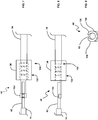
FIG. 3 is an exploded, perspective view of one embodiment of a coupler in accordance with the present disclosure. -
FIG. 4 is a cross-sectional view of a grommet as shown inFIG. 3 . -
FIG. 5 is a sectional view of one embodiment of a grommet illustrated inFIG. 4 taken along lines V-V in accordance with the present disclosure. -
FIG. 6 is an end view of the nugget in accordance with the present disclosure. -
FIG. 7 is a top view of one embodiment of a connection between the terminal in nugget and the conductors of the mineral insulated (MI) cable in accordance with the present disclosure. -
FIG. 8 is a side view of the connection shown inFIG. 7 in accordance with the present disclosure. -
FIG. 9 is an end view of the connection shown inFIG. 7 in accordance with the present disclosure. -
FIG. 10 is a side view of one embodiment of a nugget in accordance with the present disclosure -
FIG. 11 is a cross-sectional view of the nugget in accordance with the present disclosure inFIG. 10 taken along lines XI--XI. -
FIG. 12 is a top view of the nugget shown inFIG. 10 in accordance with the present disclosure. -
FIG. 13 is a side view of a wiring harness in accordance with the present disclosure. -
FIG. 14 is another side view of a wiring harness in accordance with the present disclosure. -
FIG. 15 is a partially assembled view of one embodiment of a coupler in accordance with the present disclosure. -
FIG. 16 is a top view of the end of the MI cable in accordance with the present disclosure. -
FIG. 17 is a side view of the end of the MI cable ofFIG. 16 in accordance with the present disclosure. -
FIG. 18 is a top view of the connection between the sensor and the mineral insulated cable in accordance with the present disclosure. -
FIG. 19 is a close-up view of the connection between the sensor and the mineral insulated cable shown inFIG. 18 in accordance with the present disclosure. -
FIG. 20 is a side view of the connection between the sensor and the MI cable in accordance with the present disclosure. -
FIG. 21 is a side view of the connection between the sensor and the MI cable filled with packing material in accordance with the present disclosure. -
FIG. 22 is a side view of the connection between the sensor and the MI cable forming a tip in accordance with the present disclosure. -
FIG. 23 is a top view of the end of the MI cable in accordance with the present disclosure. -
FIG. 24 is a top view of the connection between the MI cable and the wiring harness including a grommet and a nugget in accordance with the present disclosure. -
FIG. 25 is a side view of the connection between the MI cable and the wiring harness including a grommet and a nugget in accordance with the present disclosure. -
FIG. 26 is a side view of the connection between the MI cable and the wiring harness including a grommet and a nugget within the harness sleeve in accordance with the present disclosure. - Referring now to the drawings,
FIGS. 1 and 2 illustrate asensor system 10 consistent with at least one embodiment herein. Thesensor system 10 will be described in terms of an exhaust gas sensor system. For example, thesensor system 10 may comprise a temperature sensor such as, but not limited to, an exhaust gas sensor system which may be configured to be used with an internal combustion engine such as, but not limited to, a diesel engine, a gasoline engine, or the like. The output of the exhaust gas sensor system may be received by an engine control unit (ECU) or engine control module (ECM) or the like to control one or more parameters of the engine, for example, but not limited to, air/fuel ratio, boost pressure, timing or the like. It should be appreciated, however, that thesensor system 10 may comprise other types of sensor systems (e.g., but not limited to, a sensor system configured to detect, sense and/or monitor catalytic converter temperature, lubricant temperature (such as, but not limited to, engine oil, transmission oil, differential oil, or the like), brake temperature, engine coolant temperature, or the like). In addition, thesensor system 10 may include other types of sensors, for example, sensors configured to detect, sense and/or monitor other parameters including, but not limited to, pressure, speed, position or the like. - The
sensor system 10 may comprise a sensor 12 (e.g., but not limited to, a temperature sensor) coupled to aconductor housing 14, awire harness assembly 16, and acoupler 18 configured to couple theconductor housing 14 to thewire harness assembly 16. Optionally, aconnector 20 may be provided to electrically and/or mechanically couple the sensor system 10 (and in particular, the wire harness assembly 16) to a wiring loom or the like, and ultimately to at least a portion and/or subsystem of the ECU and/or ECM. Thesensor 12 may be configured to output a signal representative of the parameter being detected, sensed and/or monitored. Thesensor 12 may be selected depending on the intended parameter to be detected, sensed and/or monitored, the operating range, accuracy and/or precision desired. For example, thesensor 12 may comprise a temperature sensor configured to output a signal representative of the temperature of the exhaust gas, for example, the exhaust gas flowing through at least a portion of the exhaust gas system. According to at least one embodiment consistent herein, thetemperature sensor 12 may include a resistive temperature detector (RTD). - The
sensor system 10 may be configured to removably connect, mount, or otherwise secure thesensor 12 to a housing 13 (only a portion of which is shown for clarity) such as, but not limited to, a portion of an exhaust pipe, down pipe, exhaust manifold, or the like. For example, thesensor system 10 may include anut 22 and optionally astop flange 24. A portion of thesensor system 10 may be threaded to engage with a threaded aperture in thehousing 13, for example, until thestop flange 24 engages the housing 13 (for example, a shoulder or the like). - Because of the relative high operating temperatures of the
exhaust system 13 and the close proximity of thesensor 12 to the heat source, thesensor 12 may be electrically coupled to thewire harness assembly 16 or the like using aconductor housing 14. Theconductor housing 14 may comprise various types ofconductor housings 14 such as, but not limited to, a mineral insulated (MI) cable or ceramic insulator. For example, aMI cable 14 may comprise one or more wires disposed within a sheath 26 (e.g., a metal sheath) which are configured to electrically couple thesensor 12 to thewiring harness 16. Thesheath 26 may provide mechanical strength and/or protection to theMI cable 14 and may also position thetemperature sensor 12 and/orwiring harness 16 to prevent contact with other components. The mineral insulation may provide the necessary thermal resistance for thesensor system 10 to withstand the high temperatures experienced within anexhaust system 13. The MI cable 14may, however, be particular sensitive to moisture absorption. For example, humidity in the ambient air may cause a dielectric failure if the air has access within theMI cable 14. As discussed herein, thesensor system 10 may include acoupler 18 configured to reduce or eliminate water absorption of theMI cable 14, particularly from water being absorbed into theMI cable 14 from the end of theMI cable 14 connected to thewiring harness 16. - Turning now to
FIG. 3 , an exploded view of one embodiment of acoupler 18 is generally illustrated. Thecoupler 18 may include agrommet 28, anugget 30 and aharness sleeve 32 coupled to thesheath 26 of theconductor housing 14 which defines acavity 52 configured to receive thegrommet 28 and nugget 30. Thegrommet 28 may form a high temperature seal between thewires wiring harness 16 and theharness sleeve 32. Thegrommet 28 may include at least one longitudinally disposed passageway orcavity 36 configured to receive a portion of thewiring harness 16 and/or thewires wiring harness 16. According to at least one embodiment, thegrommet 28 may have a generally cylindrical configuration comprising a first and asecond passageway FIGS. 4 and 5 . Thepassageways wires grommet 28 may optionally include at least one radially disposed protrusion orrib 38. Theribs 38 may be disposed along the longitudinal length of thegrommet 28 and may provide multiple sealing edges with theharness sleeve 32. - The
grommet 28 may include a high temperature elastomer material. The elastomer material may include a resiliently deformable material configured to form a seal as described herein and may be configured to be partially compressed by theharness sleeve 32. For example, thegrommet 28 may include a high temperature fluorocarbon rubber. The fluorocarbon rubber may be configured to withstand temperatures of up to 536 degrees F. - Referring back to
FIG. 3 , thenugget 30 may be configured to provide strain relief for thewire harness 16 and may also be configured to provide the proper orientation and spacing of thewire terminals terminals wires wire harness 16 may be insert and/or over-molded into a high temperatureplastic nugget 30 to fix the orientation of theterminals MI cable 14 as generally illustrated inFIG. 6 . Thenugget 30 may include, at least in part, a high temperature liquid crystal polymer configured to withstand the high ambient temperatures common to exhaust systems (e.g., but not limited to, diesel exhaust systems). The material of thenugget 30 may also be configured to provide electrical insulation and to bond thewire terminals MI cable 14. - Turning now to
FIGS. 7-9 , one embodiment 48' of at least one of theterminals MI cable 14 is generally illustrated. The terminal 48' may include afirst end 150 molded within thenugget 30 coupled to one or more of thewires 34 of thewiring harness 16, for example, via welding, crimping or the like. A second, generallyopposite end 152 of the terminal 48' may include abasket 154 configured to receive a portion of the end of theconductors 60 of theMI cable 14. Thebasket 154 may facilitate alignment and may reduce any movement of the terminals 48' and theconductors 62 prior to and/or during welding. As generally illustrated, thebasket 154 may define a pocket, cavity and/or groove configured to receive the ends of theMI cable 14. Thebasket 154 may includesidewall 156 that may be guide and/or generally locate theconductor 62 as generally illustrated inFIG. 9 . - Referring now to
FIGS. 10 and 11 , thenugget 30 may optionally include an exterior shape configured to facilitate loading into an automated welding machine. For example, thenugget 30 may include one or more generally flat and/orplanar regions 40 configured to facilitate loading into an automated welding machine. Theflat region 40 may allow the automatic welding machine to properly orientate thenugget 30, for example, by providing an easily identifiable orientation feature. While thenugget 30 is illustrated having a generally flat and/orplanar region 40, thenugget 30 may also include other shapes configured to allow provide an orientation feature such as, but not limited to, an indentation, protrusion, or the like. Thenugget 30 may also include one or more protrusions molded into the top and/or bottom of thenugget 30 configured to maintain theterminals 48 separated during the molding process and to prevent electrical short circuits. - As generally illustrated in
FIGS. 10 and 12 , theexterior surface 42 of thenugget 30 may optionally include one or more indentations orgrooves 44. Thegroove 44 may include a radial groove molded into a portion of theexterior surface 42 of thenugget 30. For example, consistent with at least one embodiment thegroove 44 may be disposed about aproximal end region 46 of thenugget 30 which may be substantially adjacent to thegrommet 28 when assembled. Thegroove 44 may be configured to engage and/or mechanically couple thenugget 30 withharness sleeve 32, for example, as generally illustrated inFIG. 26 . Thegroove 44 may also be configured to self-align thenugget 30 into theharness sleeve 32 when theharness sleeve 32 is crimped as described herein. - Turning now to
FIGS. 13 and 14 , thewiring harness assembly 16 is illustrated with thegrommet 28 and thenugget 30 secured thereto. Thegrommet 28 may be advanced over a portion of thewiring harness assembly 16. Thenugget 30 may also be insert-molded to thewiring harness assembly 16. Theterminals nugget 30 and may be configured to be coupled to (for example, welded to) the ends of the MI cable 14 (not shown). Thenugget 30 may be disposed substantially adjacent to thegrommet 28. According to at least one embodiment, thegrommet 28 may directly contact against theproximal end region 46 of thenugget 30. - Referring back to
FIG. 3 , theharness sleeve 32 may include afirst end region 50 configured to be coupled to thesheath 26 of theMI cable 14. For example, thefirst end region 50 of theharness sleeve 32 may be welded to a proximal end of thesheath 26. Theharness sleeve 28 may define at least onecavity 52 configured to receive at least a portion of thegrommet 28 andnugget 30 as generally illustrated inFIG. 15 . Thecavity 52,grommet 28 and/ornugget 30 may be configured to form an interference type or a friction fit. Thecavity 52 may also have interior dimensions slightly larger than the outer dimensions of thegrommet 28 and/ornugget 30 such that thegrommet 28 and/ornugget 30 are readily received within thecavity 52 while providing a close tolerance, for example, of less than 10%, less than 5%, or less than 2%. Thecavity 52 may optionally include step or tapered/conical region 54. The taperedregion 54 may be configured to abut against a portion of thenugget 30, thereby preventing over-insertion of thenugget 30 in thecavity 52 and thereby reducing the potential for theterminals harness sleeve 32. - Once the
grommet 28 andnugget 30 are received within thecavity 52 of theharness sleeve 32, theharness sleeve 32 may be crimped to form a mechanical connection. For example, theharness sleeve 32 may be crimped about a portion overlaying thegrommet 28 to form afirst crimp 56 which may compress the elastomer material of thegrommet 28. In the non-compressed state, thepassageway 36 of thegrommet 28 may be configured to readily received theharness wire 16 and/orwires cavity 52 of theharness sleeve 32 to facilitate assembly of thesensor system 10. Thefirst crimp 56 between theharness sleeve 32 and thegrommet 28 may compress the elastomer material of thegrommet 28 thereby substantially eliminating any clearance provided between thegrommet 28 and thewires wire harness assembly 16 and forming a seal between thegrommet 28 and thewire harness assembly 16. Thefirst crimp 56 may also substantially eliminate any clearance provided between thegrommet 28 and theharness sleeve 32 thereby forming a seal. - The
harness sleeve 32 may also be crimped about a portion overlaying thenugget 30 to form asecond crimp 58. Thesecond crimp 58 between theharness sleeve 32 and thenugget 30 may generally secure thenugget 30 to theharness sleeve 32 and, along with the bonding of theterminals nugget 30, may provide strain relief for thewire harness 16. According to at least one embodiment, thesecond crimp 58 may be located about theradial groove 44 in thenugget 30 and may also facilitate alignment of thenugget 30 with respect to harnesssleeve 32. - Turning now to
FIGS. 16-22 , one embodiment illustrating the system and method for coupling thesensor 12 to theMI cable 14 is generally shown. As generally illustrated inFIGS. 16 and 17 , a distal end of theMI cable 14 may includeconductors 62. Theconductors 62 may be coupled to the corresponding leads 60 of thesensor 12 as generally illustrated inFIG. 18 and 19 . According to one embodiment, theconductors 62 and leads 60 may be electrically and/or mechanically secured to each other via one or more crimps, welds, or the like 64 and may be disposed within asensor sleeve 66 as generally illustrated inFIG. 20 . Thesensor sleeve 66 may be secured to theMI cable 14, for example, by welding, and adhesive or the like. Thesensor sleeve 66 may be filled with packingmaterial 68 such as, but not limited to, magnesium oxide (MgO), aluminum oxide, or boron nitride powder as generally illustrated inFIG. 21 . Once filled, the distal end of thesensor sleeve 66 may be crimped and/or welded to form atip 70 surrounding thesensor 12 as generally illustrated inFIG. 22 . The filledsensor 66 may be oxidized prior to welding, for example, at 650 degrees F minimum. - Turning now to
FIGS. 23-26 , one embodiment illustrating the system and method for coupling theMI cable 14 to thewiring harness 16 is generally shown. For example,FIG. 23 generally illustrates the proximal end of theMI cable 14 includingconductors 62. Theconductors 62 may be coupled to theterminals 48 molded into thenugget 30 as generally illustrate inFIGS. 24 and 25 . Theterminals 48 may receive theconductors 62 of the MI cable 14 (for example, within thebaskets 154 as generally illustrated inFIGS. 7-9 ) and they may be electrically and/or mechanically secured, for example, via one or more crimps, welds, adhesives or the like 64. Once theterminals 48 andconductors 62 are secured, thecavity 52 of theharness sleeve 32 may be advanced over thenugget 30 and at least a portion of theMI cable 14 and thegrommet 28 as generally illustrated inFIG. 26 . Theharness sleeve 32 may be aligned with thenugget 30 using, for example, thestep 54 and/or thegroove 44. Once aligned, the first andsecond crimps harness sleeve 32 to seal and/or secure theharness sleeve 32 to thegrommet 28 and/or thenugget 30. Theharness sleeve 32 may also be secured tosheath 26 of theMI cable 14, for example, by welding, and adhesive or the like 72. - While the
wiring harness 16 has been illustrated having twowires harness 16 may have fewer than or greater than twowires wiring harness 16 may include one wire, three wires, four wires or the like. Thegrommet 28 and/or thenugget 30 may therefore be configured to receive greater than or fewer than twowires conductor housing 14 may have fewer than or greater than two wires and/or terminals. - Accordingly, consistent with at least one embodiment herein, a sensor system is provided as defined in
claim 1. - In an additional aspect, the present disclosure may feature a method of assembling a sensor system as defined in
claim 13. - The present disclosure has been described in an illustrative manner. It is to be understood that the terminology which has been used is intended to be in the nature of words of description rather than of limitation. The features and aspects described with reference to particular embodiments disclosed herein may be susceptible to combination and/or application in various other embodiments described herein. Such combinations and/or applications of such described features and aspects to such other embodiments are contemplated herein.
Claims (16)
- A sensor system (10) comprising:a wiring harness (16) comprising at least one wire (34);a grommet (28) comprising at least one passageway (36) configured to receive said at least one wire (34);a molded nugget (30) molded onto a distal end region of said wiring harness (16), said nugget (30)comprising at least one terminal (48), wherein said grommet (28) is abutting against a proximal end of said molded nugget (30);a sensor (12);a conductor housing (14) coupled to said sensor (12) and comprising at least one conductor (62); anda harness sleeve (32) configured to be coupled to said conductor housing (14), said harness sleeve (32) defining at least one cavity (52) configured to receive said molded nugget (30) and at least a portion of said grommet (28), wherein said harness sleeve (32) includes a first crimp (56) coupling said harness sleeve (32) to said grommet (28), wherein said at least one terminal (48) has a first end (150) and a second, generally opposite end (152), wherein said molded nugget (30) is molded onto said first end (150) which is coupled to said at least one wire (14), and wherein said second end (152) extends beyond said molded nugget (30) and is coupled to said at least one conductor (62).
- The sensor system of claim 1, wherein an exterior surface of said grommet (28) includes at least one radially disposed rib (38).
- The sensor system of claim 1, wherein said grommet (28) includes a first (36a) and a second passageway (36b) configured to receive a first (34a) and a second wire (34b) of said wiring harness (16).
- The sensor system of claim 1, wherein said harness sleeve (32) includes a second crimp (58) coupling said harness sleeve (32) to said molded nugget (30).
- The sensor system of claim 4, wherein an exterior surface (42) of said molded nugget (30) includes at least one radially disposed groove (44), wherein said second crimp (58) couples said harness sleeve (32) to said molded nugget (30) about said radial groove (44) and locates said molded nugget (30) within said cavity (52).
- The sensor system of claim 1, wherein an inner surface of said cavity (52) comprises a stepped region configured to locate said molded nugget (30) with respect to said cavity (52), said stepped region having a cross-sectional area less than a cross-sectional area of an end region of said molded nugget (30).
- The sensor system of claim 1, wherein said first crimp (56) is configured to compress said grommet (28) to provide a seal between said harness sleeve (32) and said grommet (28) and a seal between said grommet (28) and said at least one wire of said harness wire (16).
- The sensor system of claim 1, wherein said molded nugget (30) includes at least one planar region (40) configured to facilitate loading and locking of said molded nugget (30) in said harness sleeve (32).
- The sensor system of claim 1, wherein said sensor (12) comprises a temperature sensor.
- The sensor system of claim 9, wherein said temperature sensor comprises a resistive temperature detector.
- The sensor system of claim 1, wherein said conductor housing comprises a mineral insulated cable.
- The sensor system of claim 1, wherein said sensor (12) is selected from the group consisting of a pressure sensor, a speed sensor and a position sensor.
- A method of assembling a sensor system (10) comprising:advancing at least one wire (34a,34b) of a wiring harness (16) through at least one passageway (36a,36b) of a grommet (28), said at least one wire (34a,34b) being coupled to a first end of at least one terminal (48);molding a nugget (30) over said first end (150) of said at least one terminal (48) and a distal end region of said wiring harness (16);coupling a conductor (62) of a conductor housing (14) to a second end (152) of said at least one terminal (48), said second end (152) extending beyond said molded nugget (30) ;coupling said conductor housing (14) to a harness sleeve (32) and to a sensor (12);receiving said molded nugget (30) and at least a portion of said grommet (28) within a cavity (52) of said harness sleeve (32), wherein said grommet (28) is abutting against a proximal end region of said molded nugget (30) ; andcoupling said harness sleeve (32) to said grommet (28) for form a seal.
- The method of claim 13, wherein coupling said harness sleeve (32) to said grommet (28) comprises crimping said harness sleeve (32) against said grommet (28).
- The method of claim 13, further comprising coupling said harness sleeve (32) to said molded nugget (30).
- The method of claim 15, wherein coupling said harness sleeve (32) to said molded nugget (30) comprises crimping said harness sleeve (32) to said molded nugget (30), wherein coupling said harness sleeve (32) to said molded nugget (30) reduces strain to said sensor (12).
Applications Claiming Priority (2)
| Application Number | Priority Date | Filing Date | Title |
|---|---|---|---|
| US15995509P | 2009-03-13 | 2009-03-13 | |
| PCT/US2010/027344 WO2010105268A1 (en) | 2009-03-13 | 2010-03-15 | Sensor lead sealing and strain relief |
Publications (3)
| Publication Number | Publication Date |
|---|---|
| EP2406606A1 EP2406606A1 (en) | 2012-01-18 |
| EP2406606A4 EP2406606A4 (en) | 2017-07-05 |
| EP2406606B1 true EP2406606B1 (en) | 2019-07-31 |
Family
ID=42728848
Family Applications (1)
| Application Number | Title | Priority Date | Filing Date |
|---|---|---|---|
| EP10751546.2A Active EP2406606B1 (en) | 2009-03-13 | 2010-03-15 | Sensor lead sealing and strain relief |
Country Status (6)
| Country | Link |
|---|---|
| US (2) | US8338702B2 (en) |
| EP (1) | EP2406606B1 (en) |
| JP (1) | JP5524245B2 (en) |
| KR (1) | KR101647169B1 (en) |
| CN (1) | CN102439401B (en) |
| WO (1) | WO2010105268A1 (en) |
Families Citing this family (20)
| Publication number | Priority date | Publication date | Assignee | Title |
|---|---|---|---|---|
| US8796554B2 (en) | 2011-12-30 | 2014-08-05 | Unison Industries, Llc | Mounting device and method of assembling the same |
| US10392959B2 (en) | 2012-06-05 | 2019-08-27 | General Electric Company | High temperature flame sensor |
| US9627874B2 (en) | 2012-09-12 | 2017-04-18 | Unison Industries, Llc | Mounting device and method of assembling the same |
| WO2014041171A2 (en) * | 2012-09-17 | 2014-03-20 | Tesona Gmbh & Co.Kg | High temperature sensor with a moulded protective tube |
| WO2014182745A2 (en) * | 2013-05-07 | 2014-11-13 | Stoneridge, Inc. | Exhaust gas temperature sensor |
| US9114512B2 (en) * | 2013-05-15 | 2015-08-25 | Snap-On Incorporated | Process and apparatus for locating light emitting diode in a hand tool head assembly |
| JP6290771B2 (en) * | 2014-11-14 | 2018-03-07 | 日本特殊陶業株式会社 | Measuring device |
| US9773584B2 (en) | 2014-11-24 | 2017-09-26 | General Electric Company | Triaxial mineral insulated cable in flame sensing applications |
| JP2016180676A (en) | 2015-03-24 | 2016-10-13 | 株式会社東芝 | Detection system and detection method |
| US10250004B2 (en) * | 2015-11-05 | 2019-04-02 | Magna Electronics Inc. | Method of forming a connector for an electrical cable for electrically connecting to a camera of a vehicle |
| US10230875B2 (en) | 2016-04-14 | 2019-03-12 | Magna Electronics Inc. | Camera for vehicle vision system |
| US10104937B2 (en) * | 2016-03-15 | 2018-10-23 | Nike, Inc. | Input assembly for an article of manufacture |
| DE102016118595B4 (en) | 2016-09-30 | 2018-07-26 | Heraeus Sensor Technology Gmbh | Cable, temperature measuring device and method of making a cable |
| US10428716B2 (en) * | 2016-12-20 | 2019-10-01 | Sensata Technologies, Inc. | High-temperature exhaust sensor |
| KR101832100B1 (en) * | 2017-07-27 | 2018-04-04 | 주식회사 동일그린시스 | Monitoring System for Measuring Ultrafine Dust |
| US11837816B2 (en) * | 2018-05-31 | 2023-12-05 | Hydra-Electric Company | Method of sealing cable exit for moisture and vapor intrusion |
| JP6962289B2 (en) | 2018-07-31 | 2021-11-05 | 株式会社オートネットワーク技術研究所 | Wiring member |
| CN114910104B (en) * | 2018-12-28 | 2024-09-13 | 霍尼韦尔国际公司 | Devices, systems and methods for improved sensor line retention |
| KR20200099676A (en) | 2019-02-15 | 2020-08-25 | 주식회사 신라공업 | Support assembly for sensor terminal fixing of vehicle |
| CN110578591B (en) * | 2019-09-29 | 2024-05-28 | 无锡威孚力达催化净化器有限责任公司 | Assembly integrated harness device for engine aftertreatment |
Family Cites Families (11)
| Publication number | Priority date | Publication date | Assignee | Title |
|---|---|---|---|---|
| DE3440400A1 (en) * | 1983-12-09 | 1985-06-20 | Ford-Werke AG, 5000 Köln | WATERPROOF ELECTRICAL CONNECTOR AND METHOD FOR THE PRODUCTION THEREOF |
| US5716231A (en) * | 1996-08-29 | 1998-02-10 | Snap-On Technologies, Inc. | Sensor breakout lead |
| US5837933A (en) * | 1997-08-07 | 1998-11-17 | Fligelman; Kenneth H. | Corrosion proof kill switch |
| US6291770B1 (en) * | 1999-05-14 | 2001-09-18 | Leoni Wiring Systems, Inc. | Wiring system and method therefor |
| US6440190B1 (en) * | 2000-08-16 | 2002-08-27 | Michael E. Goyetche | Portable exhaust fan for removing airborne hazardous materials |
| JP4016627B2 (en) * | 2000-11-22 | 2007-12-05 | 株式会社デンソー | Temperature sensor |
| JP2003302292A (en) * | 2002-02-07 | 2003-10-24 | Denso Corp | Sensor and manufacturing method thereof |
| US6918696B2 (en) * | 2003-01-15 | 2005-07-19 | Denso Corporation | Temperature sensor and method for manufacturing the same |
| US7665890B2 (en) * | 2006-06-22 | 2010-02-23 | Watlow Electric Manufacturing Company | Temperature sensor assembly and method of manufacturing thereof |
| US7478616B2 (en) * | 2006-11-21 | 2009-01-20 | Deere & Company | Conduit enclosure system for enclosing an engine wiring harness |
| US8653365B1 (en) * | 2009-01-23 | 2014-02-18 | Claude W. Mixon | Overfill warning wiring system for tank trucks |
-
2010
- 2010-03-15 WO PCT/US2010/027344 patent/WO2010105268A1/en not_active Ceased
- 2010-03-15 US US12/724,281 patent/US8338702B2/en active Active
- 2010-03-15 KR KR1020117022632A patent/KR101647169B1/en active Active
- 2010-03-15 EP EP10751546.2A patent/EP2406606B1/en active Active
- 2010-03-15 JP JP2011554272A patent/JP5524245B2/en active Active
- 2010-03-15 CN CN201080019426.1A patent/CN102439401B/en active Active
-
2012
- 2012-12-21 US US13/724,477 patent/US8866012B2/en active Active
Non-Patent Citations (1)
| Title |
|---|
| None * |
Also Published As
| Publication number | Publication date |
|---|---|
| JP5524245B2 (en) | 2014-06-18 |
| US8338702B2 (en) | 2012-12-25 |
| EP2406606A4 (en) | 2017-07-05 |
| EP2406606A1 (en) | 2012-01-18 |
| US20100258329A1 (en) | 2010-10-14 |
| CN102439401A (en) | 2012-05-02 |
| WO2010105268A1 (en) | 2010-09-16 |
| CN102439401B (en) | 2014-09-24 |
| JP2012520472A (en) | 2012-09-06 |
| US20140008094A1 (en) | 2014-01-09 |
| KR20110130449A (en) | 2011-12-05 |
| KR101647169B1 (en) | 2016-08-09 |
| US8866012B2 (en) | 2014-10-21 |
Similar Documents
| Publication | Publication Date | Title |
|---|---|---|
| US8866012B2 (en) | Sensor lead sealing and strain relief | |
| EP2162711B1 (en) | Temperature sensor assembly and method of manufacturing thereof | |
| US6698922B2 (en) | Temperature sensor | |
| JP5727525B2 (en) | Wall-penetrating sealed electrical connection manufacturing equipment | |
| EP2748570B1 (en) | Exhaust gas temperature sensor including a vibration reducing and/or modifying sleeve | |
| US9476775B2 (en) | Exhaust gas temperature sensor including strain relief and/or anti-vibration sleeve | |
| EP3683897B1 (en) | Waterproof structure | |
| US5820739A (en) | Measuring instrument | |
| KR102452481B1 (en) | Temperature Sensor And Manufacturing Method Of Temperature Sensor | |
| KR20180071966A (en) | High-temperature exhaust sensor | |
| US9581503B2 (en) | Sensor and sensor mounting structure | |
| EP3528349B1 (en) | Electrical connector | |
| KR102073870B1 (en) | Temperature sensor for use in the exhaust gas system of vehicle and method of manufacturing thereof | |
| US20140355653A1 (en) | Exhaust gas temperature sensor | |
| JP2006250763A (en) | Temperature sensor | |
| JP4357264B2 (en) | Gas sensor and manufacturing method thereof | |
| EP4538660A1 (en) | Temperature sensor | |
| KR102452482B1 (en) | Temperature Sensor And Manufacturing Method Thereof | |
| US9093805B2 (en) | Glow plug connector | |
| KR102726992B1 (en) | Temperature Sensor | |
| CN107959184B (en) | Cable with a protective layer |
Legal Events
| Date | Code | Title | Description |
|---|---|---|---|
| PUAI | Public reference made under article 153(3) epc to a published international application that has entered the european phase |
Free format text: ORIGINAL CODE: 0009012 |
|
| 17P | Request for examination filed |
Effective date: 20110912 |
|
| AK | Designated contracting states |
Kind code of ref document: A1 Designated state(s): AT BE BG CH CY CZ DE DK EE ES FI FR GB GR HR HU IE IS IT LI LT LU LV MC MK MT NL NO PL PT RO SE SI SK SM TR |
|
| RIN1 | Information on inventor provided before grant (corrected) |
Inventor name: MURPHY, TIM Inventor name: SPARKS, ROBERT, J. Inventor name: HESTON, MICHAEL Inventor name: NORRIS, JEFFREY, T. Inventor name: ENGELBACH, BRIAN |
|
| DAX | Request for extension of the european patent (deleted) | ||
| REG | Reference to a national code |
Ref country code: DE Ref legal event code: R079 Ref document number: 602010060286 Country of ref document: DE Free format text: PREVIOUS MAIN CLASS: G01K0007000000 Ipc: G01D0011240000 |
|
| RA4 | Supplementary search report drawn up and despatched (corrected) |
Effective date: 20170601 |
|
| RIC1 | Information provided on ipc code assigned before grant |
Ipc: G01D 11/24 20060101AFI20170526BHEP Ipc: G01K 1/14 20060101ALI20170526BHEP Ipc: G01K 1/08 20060101ALI20170526BHEP |
|
| STAA | Information on the status of an ep patent application or granted ep patent |
Free format text: STATUS: EXAMINATION IS IN PROGRESS |
|
| 17Q | First examination report despatched |
Effective date: 20180305 |
|
| GRAP | Despatch of communication of intention to grant a patent |
Free format text: ORIGINAL CODE: EPIDOSNIGR1 |
|
| STAA | Information on the status of an ep patent application or granted ep patent |
Free format text: STATUS: GRANT OF PATENT IS INTENDED |
|
| INTG | Intention to grant announced |
Effective date: 20190214 |
|
| GRAS | Grant fee paid |
Free format text: ORIGINAL CODE: EPIDOSNIGR3 |
|
| GRAA | (expected) grant |
Free format text: ORIGINAL CODE: 0009210 |
|
| STAA | Information on the status of an ep patent application or granted ep patent |
Free format text: STATUS: THE PATENT HAS BEEN GRANTED |
|
| AK | Designated contracting states |
Kind code of ref document: B1 Designated state(s): AT BE BG CH CY CZ DE DK EE ES FI FR GB GR HR HU IE IS IT LI LT LU LV MC MK MT NL NO PL PT RO SE SI SK SM TR |
|
| REG | Reference to a national code |
Ref country code: CH Ref legal event code: EP Ref country code: GB Ref legal event code: FG4D |
|
| REG | Reference to a national code |
Ref country code: DE Ref legal event code: R096 Ref document number: 602010060286 Country of ref document: DE |
|
| REG | Reference to a national code |
Ref country code: AT Ref legal event code: REF Ref document number: 1161393 Country of ref document: AT Kind code of ref document: T Effective date: 20190815 |
|
| REG | Reference to a national code |
Ref country code: IE Ref legal event code: FG4D |
|
| REG | Reference to a national code |
Ref country code: NL Ref legal event code: MP Effective date: 20190731 |
|
| REG | Reference to a national code |
Ref country code: LT Ref legal event code: MG4D |
|
| REG | Reference to a national code |
Ref country code: AT Ref legal event code: MK05 Ref document number: 1161393 Country of ref document: AT Kind code of ref document: T Effective date: 20190731 |
|
| PG25 | Lapsed in a contracting state [announced via postgrant information from national office to epo] |
Ref country code: AT Free format text: LAPSE BECAUSE OF FAILURE TO SUBMIT A TRANSLATION OF THE DESCRIPTION OR TO PAY THE FEE WITHIN THE PRESCRIBED TIME-LIMIT Effective date: 20190731 Ref country code: HR Free format text: LAPSE BECAUSE OF FAILURE TO SUBMIT A TRANSLATION OF THE DESCRIPTION OR TO PAY THE FEE WITHIN THE PRESCRIBED TIME-LIMIT Effective date: 20190731 Ref country code: NL Free format text: LAPSE BECAUSE OF FAILURE TO SUBMIT A TRANSLATION OF THE DESCRIPTION OR TO PAY THE FEE WITHIN THE PRESCRIBED TIME-LIMIT Effective date: 20190731 Ref country code: BG Free format text: LAPSE BECAUSE OF FAILURE TO SUBMIT A TRANSLATION OF THE DESCRIPTION OR TO PAY THE FEE WITHIN THE PRESCRIBED TIME-LIMIT Effective date: 20191031 Ref country code: LT Free format text: LAPSE BECAUSE OF FAILURE TO SUBMIT A TRANSLATION OF THE DESCRIPTION OR TO PAY THE FEE WITHIN THE PRESCRIBED TIME-LIMIT Effective date: 20190731 Ref country code: NO Free format text: LAPSE BECAUSE OF FAILURE TO SUBMIT A TRANSLATION OF THE DESCRIPTION OR TO PAY THE FEE WITHIN THE PRESCRIBED TIME-LIMIT Effective date: 20191031 Ref country code: FI Free format text: LAPSE BECAUSE OF FAILURE TO SUBMIT A TRANSLATION OF THE DESCRIPTION OR TO PAY THE FEE WITHIN THE PRESCRIBED TIME-LIMIT Effective date: 20190731 Ref country code: SE Free format text: LAPSE BECAUSE OF FAILURE TO SUBMIT A TRANSLATION OF THE DESCRIPTION OR TO PAY THE FEE WITHIN THE PRESCRIBED TIME-LIMIT Effective date: 20190731 Ref country code: PT Free format text: LAPSE BECAUSE OF FAILURE TO SUBMIT A TRANSLATION OF THE DESCRIPTION OR TO PAY THE FEE WITHIN THE PRESCRIBED TIME-LIMIT Effective date: 20191202 |
|
| PG25 | Lapsed in a contracting state [announced via postgrant information from national office to epo] |
Ref country code: LV Free format text: LAPSE BECAUSE OF FAILURE TO SUBMIT A TRANSLATION OF THE DESCRIPTION OR TO PAY THE FEE WITHIN THE PRESCRIBED TIME-LIMIT Effective date: 20190731 Ref country code: GR Free format text: LAPSE BECAUSE OF FAILURE TO SUBMIT A TRANSLATION OF THE DESCRIPTION OR TO PAY THE FEE WITHIN THE PRESCRIBED TIME-LIMIT Effective date: 20191101 Ref country code: ES Free format text: LAPSE BECAUSE OF FAILURE TO SUBMIT A TRANSLATION OF THE DESCRIPTION OR TO PAY THE FEE WITHIN THE PRESCRIBED TIME-LIMIT Effective date: 20190731 Ref country code: IS Free format text: LAPSE BECAUSE OF FAILURE TO SUBMIT A TRANSLATION OF THE DESCRIPTION OR TO PAY THE FEE WITHIN THE PRESCRIBED TIME-LIMIT Effective date: 20191130 |
|
| PG25 | Lapsed in a contracting state [announced via postgrant information from national office to epo] |
Ref country code: TR Free format text: LAPSE BECAUSE OF FAILURE TO SUBMIT A TRANSLATION OF THE DESCRIPTION OR TO PAY THE FEE WITHIN THE PRESCRIBED TIME-LIMIT Effective date: 20190731 |
|
| PG25 | Lapsed in a contracting state [announced via postgrant information from national office to epo] |
Ref country code: PL Free format text: LAPSE BECAUSE OF FAILURE TO SUBMIT A TRANSLATION OF THE DESCRIPTION OR TO PAY THE FEE WITHIN THE PRESCRIBED TIME-LIMIT Effective date: 20190731 Ref country code: RO Free format text: LAPSE BECAUSE OF FAILURE TO SUBMIT A TRANSLATION OF THE DESCRIPTION OR TO PAY THE FEE WITHIN THE PRESCRIBED TIME-LIMIT Effective date: 20190731 Ref country code: IT Free format text: LAPSE BECAUSE OF FAILURE TO SUBMIT A TRANSLATION OF THE DESCRIPTION OR TO PAY THE FEE WITHIN THE PRESCRIBED TIME-LIMIT Effective date: 20190731 Ref country code: EE Free format text: LAPSE BECAUSE OF FAILURE TO SUBMIT A TRANSLATION OF THE DESCRIPTION OR TO PAY THE FEE WITHIN THE PRESCRIBED TIME-LIMIT Effective date: 20190731 Ref country code: DK Free format text: LAPSE BECAUSE OF FAILURE TO SUBMIT A TRANSLATION OF THE DESCRIPTION OR TO PAY THE FEE WITHIN THE PRESCRIBED TIME-LIMIT Effective date: 20190731 |
|
| PG25 | Lapsed in a contracting state [announced via postgrant information from national office to epo] |
Ref country code: SM Free format text: LAPSE BECAUSE OF FAILURE TO SUBMIT A TRANSLATION OF THE DESCRIPTION OR TO PAY THE FEE WITHIN THE PRESCRIBED TIME-LIMIT Effective date: 20190731 Ref country code: CZ Free format text: LAPSE BECAUSE OF FAILURE TO SUBMIT A TRANSLATION OF THE DESCRIPTION OR TO PAY THE FEE WITHIN THE PRESCRIBED TIME-LIMIT Effective date: 20190731 Ref country code: SK Free format text: LAPSE BECAUSE OF FAILURE TO SUBMIT A TRANSLATION OF THE DESCRIPTION OR TO PAY THE FEE WITHIN THE PRESCRIBED TIME-LIMIT Effective date: 20190731 Ref country code: IS Free format text: LAPSE BECAUSE OF FAILURE TO SUBMIT A TRANSLATION OF THE DESCRIPTION OR TO PAY THE FEE WITHIN THE PRESCRIBED TIME-LIMIT Effective date: 20200224 |
|
| REG | Reference to a national code |
Ref country code: DE Ref legal event code: R097 Ref document number: 602010060286 Country of ref document: DE |
|
| PLBE | No opposition filed within time limit |
Free format text: ORIGINAL CODE: 0009261 |
|
| STAA | Information on the status of an ep patent application or granted ep patent |
Free format text: STATUS: NO OPPOSITION FILED WITHIN TIME LIMIT |
|
| PG2D | Information on lapse in contracting state deleted |
Ref country code: IS |
|
| PG25 | Lapsed in a contracting state [announced via postgrant information from national office to epo] |
Ref country code: IS Free format text: LAPSE BECAUSE OF FAILURE TO SUBMIT A TRANSLATION OF THE DESCRIPTION OR TO PAY THE FEE WITHIN THE PRESCRIBED TIME-LIMIT Effective date: 20191030 |
|
| 26N | No opposition filed |
Effective date: 20200603 |
|
| PG25 | Lapsed in a contracting state [announced via postgrant information from national office to epo] |
Ref country code: SI Free format text: LAPSE BECAUSE OF FAILURE TO SUBMIT A TRANSLATION OF THE DESCRIPTION OR TO PAY THE FEE WITHIN THE PRESCRIBED TIME-LIMIT Effective date: 20190731 |
|
| PG25 | Lapsed in a contracting state [announced via postgrant information from national office to epo] |
Ref country code: MC Free format text: LAPSE BECAUSE OF FAILURE TO SUBMIT A TRANSLATION OF THE DESCRIPTION OR TO PAY THE FEE WITHIN THE PRESCRIBED TIME-LIMIT Effective date: 20190731 |
|
| REG | Reference to a national code |
Ref country code: CH Ref legal event code: PL |
|
| REG | Reference to a national code |
Ref country code: BE Ref legal event code: MM Effective date: 20200331 |
|
| PG25 | Lapsed in a contracting state [announced via postgrant information from national office to epo] |
Ref country code: LU Free format text: LAPSE BECAUSE OF NON-PAYMENT OF DUE FEES Effective date: 20200315 |
|
| PG25 | Lapsed in a contracting state [announced via postgrant information from national office to epo] |
Ref country code: CH Free format text: LAPSE BECAUSE OF NON-PAYMENT OF DUE FEES Effective date: 20200331 Ref country code: IE Free format text: LAPSE BECAUSE OF NON-PAYMENT OF DUE FEES Effective date: 20200315 Ref country code: FR Free format text: LAPSE BECAUSE OF NON-PAYMENT OF DUE FEES Effective date: 20200331 Ref country code: LI Free format text: LAPSE BECAUSE OF NON-PAYMENT OF DUE FEES Effective date: 20200331 |
|
| PG25 | Lapsed in a contracting state [announced via postgrant information from national office to epo] |
Ref country code: BE Free format text: LAPSE BECAUSE OF NON-PAYMENT OF DUE FEES Effective date: 20200331 |
|
| GBPC | Gb: european patent ceased through non-payment of renewal fee |
Effective date: 20200315 |
|
| PG25 | Lapsed in a contracting state [announced via postgrant information from national office to epo] |
Ref country code: GB Free format text: LAPSE BECAUSE OF NON-PAYMENT OF DUE FEES Effective date: 20200315 |
|
| PG25 | Lapsed in a contracting state [announced via postgrant information from national office to epo] |
Ref country code: MT Free format text: LAPSE BECAUSE OF FAILURE TO SUBMIT A TRANSLATION OF THE DESCRIPTION OR TO PAY THE FEE WITHIN THE PRESCRIBED TIME-LIMIT Effective date: 20190731 Ref country code: CY Free format text: LAPSE BECAUSE OF FAILURE TO SUBMIT A TRANSLATION OF THE DESCRIPTION OR TO PAY THE FEE WITHIN THE PRESCRIBED TIME-LIMIT Effective date: 20190731 |
|
| PG25 | Lapsed in a contracting state [announced via postgrant information from national office to epo] |
Ref country code: MK Free format text: LAPSE BECAUSE OF FAILURE TO SUBMIT A TRANSLATION OF THE DESCRIPTION OR TO PAY THE FEE WITHIN THE PRESCRIBED TIME-LIMIT Effective date: 20190731 |
|
| PGFP | Annual fee paid to national office [announced via postgrant information from national office to epo] |
Ref country code: DE Payment date: 20260320 Year of fee payment: 17 |