EP2406174B1 - Cartridge for the generation of hydrogen - Google Patents
Cartridge for the generation of hydrogen Download PDFInfo
- Publication number
- EP2406174B1 EP2406174B1 EP10751253.5A EP10751253A EP2406174B1 EP 2406174 B1 EP2406174 B1 EP 2406174B1 EP 10751253 A EP10751253 A EP 10751253A EP 2406174 B1 EP2406174 B1 EP 2406174B1
- Authority
- EP
- European Patent Office
- Prior art keywords
- cartridge
- cavity
- hydrogen
- water
- igniter
- Prior art date
- Legal status (The legal status is an assumption and is not a legal conclusion. Google has not performed a legal analysis and makes no representation as to the accuracy of the status listed.)
- Not-in-force
Links
Images



Classifications
-
- C—CHEMISTRY; METALLURGY
- C01—INORGANIC CHEMISTRY
- C01B—NON-METALLIC ELEMENTS; COMPOUNDS THEREOF; METALLOIDS OR COMPOUNDS THEREOF NOT COVERED BY SUBCLASS C01C
- C01B3/00—Hydrogen; Gaseous mixtures containing hydrogen; Separation of hydrogen from mixtures containing it; Purification of hydrogen; Reversible storage of hydrogen
- C01B3/02—Production of hydrogen; Production of gaseous mixtures containing hydrogen
- C01B3/06—Production of hydrogen; Production of gaseous mixtures containing hydrogen by reaction of inorganic compounds containing electro-positively bound hydrogen with inorganic reducing agents
- C01B3/08—Production of hydrogen; Production of gaseous mixtures containing hydrogen by reaction of inorganic compounds containing electro-positively bound hydrogen with inorganic reducing agents by reaction of inorganic compounds with metals
-
- C—CHEMISTRY; METALLURGY
- C01—INORGANIC CHEMISTRY
- C01B—NON-METALLIC ELEMENTS; COMPOUNDS THEREOF; METALLOIDS OR COMPOUNDS THEREOF NOT COVERED BY SUBCLASS C01C
- C01B3/00—Hydrogen; Gaseous mixtures containing hydrogen; Separation of hydrogen from mixtures containing it; Purification of hydrogen; Reversible storage of hydrogen
- C01B3/02—Production of hydrogen; Production of gaseous mixtures containing hydrogen
- C01B3/06—Production of hydrogen; Production of gaseous mixtures containing hydrogen by reaction of inorganic compounds containing electro-positively bound hydrogen with inorganic reducing agents
- C01B3/08—Production of hydrogen; Production of gaseous mixtures containing hydrogen by reaction of inorganic compounds containing electro-positively bound hydrogen with inorganic reducing agents by reaction of inorganic compounds with metals
- C01B3/10—Production of hydrogen; Production of gaseous mixtures containing hydrogen by reaction of inorganic compounds containing electro-positively bound hydrogen with inorganic reducing agents by reaction of inorganic compounds with metals by reaction of water vapour with metals
-
- Y—GENERAL TAGGING OF NEW TECHNOLOGICAL DEVELOPMENTS; GENERAL TAGGING OF CROSS-SECTIONAL TECHNOLOGIES SPANNING OVER SEVERAL SECTIONS OF THE IPC; TECHNICAL SUBJECTS COVERED BY FORMER USPC CROSS-REFERENCE ART COLLECTIONS [XRACs] AND DIGESTS
- Y02—TECHNOLOGIES OR APPLICATIONS FOR MITIGATION OR ADAPTATION AGAINST CLIMATE CHANGE
- Y02E—REDUCTION OF GREENHOUSE GAS [GHG] EMISSIONS, RELATED TO ENERGY GENERATION, TRANSMISSION OR DISTRIBUTION
- Y02E60/00—Enabling technologies; Technologies with a potential or indirect contribution to GHG emissions mitigation
- Y02E60/30—Hydrogen technology
- Y02E60/36—Hydrogen production from non-carbon containing sources, e.g. by water electrolysis
Definitions
- the invention relates generally to the generation of hydrogen and specifically to a cartridge for the generation of hydrogen.
- Hydrogen can be used as a source of energy in many hydrogen-consuming systems such as fuel cells, internal combustion engines, and portable power equipment and tools. Devices that consume hydrogen for energy must be connected to a source for hydrogen such as those that directly utilize hydrogen in either liquid or gaseous form and those that utilize hydrogen in chemical compounds such as water. Some of the systems that store such chemically bonded hydrogen utilize a cartridge for containing the water along with other components. When hydrogen is stored in chemical compounds such as water, it must be converted to consumable hydrogen by a reaction prior to use as hydrogen.
- One conventional process for releasing bonded hydrogen from water is electrolysis.
- electrolysis an electrical differential is applied to water at a cathode and an anode, and an advantage of this system is that a low voltage of electricity can be used.
- Another reaction to release hydrogen from water is that of aluminum and water to generate aluminum oxide and hydrogen gas.
- US 5 052 272 discloses such a cartridge. This reaction can be self sustaining, but it requires high temperatures to generate substantial hydrogen production. One way to do this is by heating aluminum and water that are in close proximity with thermite, but most conventional systems for igniting the thermite require a high voltage differential.
- one problem with such cartridges is that high voltages are required to initiate the reaction.
- Another problem with cartridges configured to generate hydrogen through the reaction of a metal with an oxidizing agent is that the reaction can proceed prematurely because of contact between the reactants.
- Another problem is that structure utilized to form the cartridge and to contain the reactants remains as waste after the cartridge is used.
- Another problem is that the cost of conventional cartridges is too high to allow for economical one-time use, i.e. conventional cartridges are not expendable.
- the present invention provides a cartridge for the rapid generation of hydrogen very rapidly in response to demand, at high pressures, and at high temperatures.
- the cartridge includes consumable structural components such that solid waste remaining after discharge of a cartridge is minimized.
- the cartridge of the present invention is configured for use in a system that provides hydrogen at a generally constant pressure.
- a cartridge for the generation of hydrogen includes a case, an igniter, and a structural component.
- the case defines an interior cavity and the igniter is positioned within the cavity.
- the structural component is also positioned within the cavity and is formed of a particulate embedded in a matrix and the particulate includes a metallic material.
- An oxidizing agent is positioned within the cavity, wherein the oxidizing agent is water.
- the matrix of the structural component includes at least one member selected from the group consisting of nitrocellulose, dextrin, guar gum, gum Arabic, shellac, and synthetic organic polymers, and is configured to be impermeable to water so that the metallic material is isolated from the water.
- the igniter is configured to generate a temperature that is between 1371 °C (2,500 degrees Fahrenheit) and 3316°C (6,000 degrees Fahrenheit) so as to remove the matrix from the structural component such that the metallic material is no longer isolated from water and to initiate a reaction between the metallic material and the oxidizing agent to generate hydrogen.
- the structural component configured to generally maintain the position of the igniter relative to the case.
- the structural component is also configured to define a plurality of chambers within the cavity and the oxidizing agent is positioned within the plurality of chambers.
- the matrix includes nitrocellulose.
- the case is also formed of the particulate embedded in the matrix.
- the igniter includes thermite.
- the water is gelatinized.
- the metallic material includes aluminum.
- an electrical element is positioned within the igniter and is electrically connected with an exterior surface of the case.
- the igniter is configured to ignite when a voltage is applied to the electrical element and the igniter is configured to generate sufficient heat such that at a least a portion of the matrix is removed from the structural component thereby exposing sufficient metallic material to the oxidizing agent at a sufficiently high temperature to initiate a chemical reaction between the oxidizing agent and the metallic material thereby generating hydrogen.
- the case includes a metallic cap that is electrically connected to the electrical element such that the cap forms part of an electrical circuit when the voltage is applied to the electrical element.
- the cap is configured to rupture such that an opening is defined through the cap for the release of hydrogen therethrough and such that the ruptured cap is retained in contact with the case.
- a cartridge that includes a case, an igniter, and an insert.
- the case defines an interior cavity.
- the igniter is configured to ignite when an electrical element embedded therein is exposed to an electrical voltage differential.
- the insert is configured to define a plurality of chambers within the cavity and the insert includes aluminum particles that are embedded in a nitrocellulose matrix.
- An oxidizing agent including chemically bonded hydrogen is positioned within each chamber. The igniter is configured to initiate a reaction between the aluminum particles and the oxidizing agent that generates hydrogen.
- the pressure within the cavity increases such that a portion of the case ruptures and hydrogen is discharged from the cavity.
- substantially all material created by the reaction other than hydrogen remain associated with the case.
- a device for the generation of hydrogen includes a case and a spacer.
- the case that defines a cavity, and the spacer is positioned within the cavity and defines multiple chambers within the cavity.
- the spacer includes a metal and a binding agent.
- An oxidizing agent is positioned within the chambers. The spacer is configured such that there is substantially no reaction between the metal and the oxidizing agent until an ignition composition is ignited and the binding agent is consumed such that the metal and the oxidizing agent are exposed to each other.
- the metal is aluminum
- the oxidizing agent is water
- the ignition composition is thermite
- the binding agent is nitrocellulose
- the case is formed of the aluminum embedded in nitrocellulose.
- the total amount of aluminum contained in the spacer and the case is roughly in stoichiometric proportions with the water.
- the metallic insert is configured to position the first reactant and the second reactant such that they are sufficiently near the igniter such that the rapid reaction of the first reactant and the second reactant can be initiated by the igniter.
- the binder forms a coating on a solid metal spacer.
- the metallic insert includes aluminum powder in a nitrocellulose matrix.
- Embodiments of the present invention are directed to a cartridge for the rapid generation of hydrogen from a first reactant that contains hydrogen and a second reactant that contains metal.
- the reaction can be initiated by a low electrical voltage and consumes at least some of the structure required to position the reactants such that they are sufficiently close to each other and to an igniter for the rapid reaction to be initiated by the igniter.
- a cartridge 10 for generating hydrogen includes a case 20 configured to receive a cap 50, an ignition assembly 70, and a spacer 100.
- the cartridge 10 is configured to be received in a reaction assembly 200 and discharged therein to generate hydrogen.
- cartridge 10 includes a generally cup-shaped case 20 having a closed end 22.
- a circumferential groove 28 is defined around case 20 at closed end 22 and groove 28 is spaced-away from an outer surface 29 of closed end 22.
- Closed end 22 is shaped such that outer surface 29 defines a recess 31. Closed end 22 also defines an inner surface 23.
- Case 20 includes a wall 24 that extends away from closed end 22 toward an open end 26 and defining an inner surface 34.
- Surface 34 and surface 23 define a cup-shaped cavity 66.
- a first passageway 32 is defined through the closed end 22 of case 20 such that it extends from recess 31 to inner surface 23 thereby connecting outer surface 29 with cup-shaped cavity 66.
- a shoulder 38 that extends from an outer surface 39 of wall 24 to a land area 42 is defined by wall 24.
- a lip 43 is formed by wall 24 at open end 26 of case 20.
- case 20 is formed of a thermoplastic material.
- case 20 can be formed of one of the following: nitrocellulose, cellulose, metal, metallic material, thermoplastic, or a combination thereof.
- the thermoplastic can include polycarbonate (commercially known by various trade names including Lexan®), polyoxymethylene (commercially known by various trade names including Delrin®), polymethyl methacrylate (commercially known by various trade names including Plexiglas®), and a combination thereof.
- cap 50 includes a generally circular wall 52 that defines an inner surface 54 and an outer surface 56.
- Cap 50 is positioned across the open end 26 of cup-shaped case 20 such that cavity 66 is enclosed.
- a flange 58 is positioned around the circumference of wall 52 of cap 50 and extends away from inner surface 54 of wall 52.
- Flange 58 has a circumferential recess 62 formed therein that is configured to engage lip 43 of case 20, and thus be retained on open end 26 of case 20.
- a plurality of grooves 64 are formed on the outer surface 54 of cap 50. In the illustrated embodiment, grooves 64 are positioned to form a cross-shaped pattern, but it should be appreciated that in other embodiments, grooves 64 can have other configurations.
- Grooves 64 of cap 50 are dimensioned to fail at a predetermined rupture pressure.
- the rupture pressure is less than a peak, i.e. maximum, pressure generated within cavity 66 by the reaction of the metallic first reactant and the oxidizing second reactant in cartridge 10 in firing chamber 250.
- cap 50 is configured as a burst disk such that cap 50 is configured to preferentially rupture to form an opening 51 in wall 52 as shown in FIG. 6 . Opening 51 is configured to fluidly connect cavity 66 with a region outside of cartridge 10.
- the rupture pressure is between about 34,5 bar (500 psi) and about 1034,2 bar (15,000 psi); more preferably, the rupture pressure is between about 206,8 bar (3000 psi) and about 896,3 bar (13,000 psi); and even more preferably, the rupture pressure is between about 620,5 bar (9,000 psi) and about 758,4 bar (11,000 psi).
- a least one petal 65 is formed when cap 50 ruptures along grooves 64.
- petal 65 remains attached to flange 58 and flange 58 remains engaged with case 20. In this manner, the components of cap 50 that remain after discharge of cartridge 10 are retained on case 20 and can be recycled or disposed of along with case 20.
- cap 50 is formed of a metal.
- cap 50 can include at least one of the following: stainless steel, brass, nitrocellulose, a fiber reinforced resin, electrically conductive elements, and a combination thereof.
- spacer 100 is positioned within cavity 66.
- spacer 100 is generally longitudinal and has a plurality of ribs 103 that are distributed radially around a central core 104.
- a passageway 108 is formed through core 104 of spacer 100.
- Each rib 103 extends toward inner surface 34 of wall 24 such that a plurality of chambers 106 are defined by ribs 103, inner surface 34 of wall 24 and closed end 22, and the base surface 73 of primary ignition block 72.
- the plurality of chambers 106 are radially disposed and are configured to receive water as an oxidizing agent such as water 107.
- spacer 100 can be configured as cylinder that defines a central chamber or a cylinder that defines a first central chamber and a second annular chamber.
- wall 24 includes radially disposed ribs that extend into cavity 66 and there is no spacer 100.
- path P is formed along one of the radially disposed ribs.
- spacer 100 includes a metallic particulate 101 that is embedded in a matrix 102 as can be seen in FIG. 5 .
- Metallic particulate 101 includes the metal first reactant.
- Matrix 102 is formed of a binding agent and is configured to be substantially impermeable to the oxidizing second reactant such the metallic particulate 101, and thus the metal first reactant, is substantially isolated from the water 107.
- matrix 102 is consumable during the rapid reaction of the metal first reactant and the oxidizing second reactant as discussed further below.
- the term “consumable” refers to the quality of changing form or reacting such that the metallic particulate 101, and thus the metal first reactant, is substantially no longer isolated from water 107.
- matrix 102 is configured to limit unintended reactions between water 107 and metallic particulate 101 such that no additional barrier between the metallic portion of spacer 100 and water 107 is required.
- the metallic particulate 101 of spacer 100 can include as the first metal reactant metals such as aluminum, magnesium, iron, sodium, potassium, titanium, and combinations thereof.
- metallic particulate 101 includes aluminum and it is believed that aluminum having any purity is suitable for use as the reactive metal, and therefore, any alloy of aluminum is suitable for use as a metallic insert of the present invention.
- spacer 100 can include one of the following metallic materials: a woven metal mesh, a metal wool, discrete metal pellets, and a combination thereof.
- the metallic material is coated with the binding agent.
- the matrix 102 is a material that can function to bind metallic particulate 101 together. Other desirable characteristics of the matrix are: it is soluble and when solvated can be mixed with particulate 101, it can be easily dried or cured to form the desired component of cartridge 10, and it is consumable during a rapid reaction between the metal first reactant and the oxidizing second reactant.
- the matrix includes nitrocellulose.
- the matrix can include one of the following: nitrocellulose, dextrin, guar gum, gum Arabic, shellac, synthetic organic polymers, other organic materials, and a combination thereof.
- the percentage of metallic particulate 101 relative to the combined weight of metal particulate 101 and matrix 102 in spacer 100 is preferably between about 80% and about 99.9%; more preferably between about 88% and 98%; and most preferably between about 92% and 96%. It should be appreciated that structures other than spacer 100 disclosed herein that are formed of metallic particulate 101 embedded in matrix 102 have substantially similar compositions to that of spacer 100.
- the water can be pure or can contain various contaminates such as salts, metals, minerals, etc.
- the water can be a liquid or substantially solidified by combination with a gelatinizing agent.
- the ratio of the metallic first reactant, for example aluminum, and the oxidizing agent water is generally equal to the stoichiometric ratio of the oxidizing reaction between the two components. Therefore, when the metallic first reactant is aluminum and the oxidizing second reactant is water, the stoichiometric ratio is about one to one, and aluminum and water are contained in cartridge 10 in a ratio of about one to one. Referring to metal particles 101, they are provided such that the reactive metal contained therein is in an appropriate ratio.
- the mass of metallic particles 101 contained within the cartridge 10 is generally equal to the mass of water 107 in cartridge 10.
- the mass of metallic particles 101 contained within cartridge 10 is generally two times the mass of water 107 in cartridge 10.
- Spacer 100 is configured to position ignition assembly 70 within cavity 66 such that assembly 70 is near cap 50 and in this regard, spacer 100 is a structural component.
- wall 24 of case 20 includes tabs or ribs that are configured to position ignition assembly 70 within cavity 66.
- Spacer 100 is configured to extend within cavity 66 from closed end 22 to assembly 70. Such that one end of spacer 100 is near surface 23 and another end of spacer 100 is near surface 73. It should be appreciated that while spacer 100 is configured to mechanically separate assembly 70 from closed end 22, in some embodiments spacer 100 is movable relatively one or both of assembly 70 and closed end 22, and in addition, might not be in direct contact with one or both of assembly 70 and closed end 22.
- Ignition assembly 70 is configured as an igniter and includes a primary ignition block 72 having a recess 74 formed therein.
- ignition refers to a structure configured to generate sufficient temperature to initiate, i.e. ignite, a reaction between reactants.
- a passageway 78 is defined from recess 74 through a base portion of primary ignition block 72 to a base surface 73 defined by the base portion of primary ignition block 72.
- Recess 74 is dimensioned to receive a pre-ignition block 76.
- both primary ignition block 72 and pre-ignition block 76 are generally cylindrical.
- Primary ignition block 72 includes thermite.
- the term "thermite” refers to a composition that includes a metal oxide that acts as an oxidizing agent and a metal to be oxidized by the oxidizing agent.
- the metal oxide can be black or blue iron oxide (Fe 3 O 4 ), red iron(III) oxide (Fe 2 O 3 ), manganese oxide (MnO 2 ), Chromium (III) oxide Cr 2 O 3 , cuprous oxide (Cu 2 O), cupric oxide, (copper (II) oxide, CuO), other metal oxide, or a combination thereof.
- the metal to be oxidized can be aluminum or other reactive metal.
- the metal oxide is iron oxide (Fe 3 O 4 ).
- the thermite is formed together with a binding agent into a desired shape and the binding agent is a nitrocellulose lacquer.
- the particles of thermite are retained within a matrix of nitrocellulose.
- the primary ignition block 72 is formed of thermite that is configured to retain its shape without a binder, i.e. compressed or solid thermite.
- the thermite can be in the form of particles that are retained in a container or wrapping (not shown) that is configured to support and shape primary ignition block 72.
- Pre-ignition block 76 is formed of a pre-ignition compound that includes potassium perchlorate, magnesium, and aluminum.
- Pre-ignition block 76 includes an element 82.
- Element 82 is configured to electrically connect cap 50 with a region adjacent one end of passageway 78 of primary ignition block 72. It should be appreciated that element 82 can be any electrical element configured to generate heat when exposed to an electrical differential.
- element 82 is a bridge wire. As used herein, the term "bridge wire" refers to a relatively thin resistance wire used to ignite a pyrotechnic composition.
- Pre-ignition block 76 is formed by a molding process in which the pre-ignition compound is formed of particles that are mixed with a binding agent and molded to a desired shape.
- the binding agent can be a lacquer such as nitrocellulose lacquer and in such an embodiment, pre-ignition block 76 is formed of particles of the pre-ignition compound embedded in a matrix of nitrocellulose.
- the mixture of binding agent and pre-ignition compound is molded around element 82 such that element 82 is also embedded in the matrix of nitrocellulose.
- pre-ignition block 76 can include solid or particulate components and can be positioned within a container or wrapping (not shown) that is configured to support and shape pre-ignition block 76. Further, element 82 can be positioned around pre-ignition block 76 or through a passageway formed therein after initial shaping of the pre-ignition block is complete.
- Pre-ignition block 76 is configured to ignite when element 82 is exposed to an electrical voltage differential that is preferably between about 1 volts and about 100 volts, more preferably between about 5 volts and about 30 volts, and even more preferably between about 10 volts and about 15 volts, and most preferably about 12 volts.
- Pre-ignition block 76 is configured to generate a temperature upon ignition that is sufficient to ignite primary ignition block 72.
- Primary ignition block 72 is configured to generate a temperature after ignition that is sufficient to initiate an oxidation reaction between the metal first reactant, and the oxidizing second reactant. In other embodiments, the ignition of composition 72 is sufficient to initiate a similar oxidation reaction that generates hydrogen.
- Primary ignition block 72 is configured to generate a temperature that is between 1371 °C (2,500 degrees Farenheit) and 3316°C (6,000 degrees Farenheit), more preferably between about 1788°C (3,250 degrees Farenheit) and about 2760°C (5,000 degrees Farenheit), and even more preferably between about 1927 °C (3,500 degrees Farenheit) and about 2482 °C (4,500 degrees Farenheit).
- Ignition assembly 70 is configured to initiate a reaction between spacer 100 and water as will be discussed further below.
- passageway 32 of closed end 22, passageway 108 of spacer 100, and passageway 78 of primary ignition block 72 are aligned to form a continuous primary passageway that connects outer surface 29 of closed end 22 with element 82.
- the primary passageway is configured to receive a conductor 112 that is configured to electrically contact element 82 at an end 116 such that element 82 is electrically connected with a button 114.
- Conductor 112 is also configured to be electrically insulated from other components of cartridge 10.
- conductor 112 includes one of the following: a solid metal wire, stranded metal wire, aluminum, silver, other metal, carbon, other conductive non-metal, and a combination thereof.
- conductor 112 is an insulated metallic wire.
- Button 114 is configured to provide a surface for electrical contact that is positioned exterior of cartridge 10, and button 114 is configured to be received in axial recess 31 of closed end 22.
- button 114 includes one of the following: aluminum, silver, other metal, carbon, other conductive non-metal, and a combination thereof.
- an electrically conductive path P is formed that extends from outer surface 29 of closed end 22 to outer surface 56 of cap 50. Path P is configured to conduct an electric current such that the pre-ignition block 76 can be ignited as will be discussed below with regard to the operation of the present invention.
- cartridge 10 is configured to be received by a reaction assembly 200 and activated therein.
- Reaction assembly 200 includes a hydrogen containment vessel 204, a magazine 240, a loading device 241 and a firing chamber 250.
- Containment vessel 204 has a wall 205 that defines a cavity 206.
- a pressure sensor 208 is fluidly connected through wall 205 to cavity 206. In the illustrated embodiment, pressure sensor 208 is configured to generate a signal indicative of the pressure within cavity 206 and includes an operator interface.
- a discharge tube 214 defines a passageway that fluidly connects cavity 206 with a device or region outside of reaction assembly 200.
- a control valve 212 positioned in discharge tube 214 and is configured to control the flow of fluid through discharge tube 214.
- control valve 212 is a pressure regulator valve that is configured to maintain a predetermined pressure within cavity 206.
- a valve 216 is positioned on wall 205 and is configured to vent cavity 206 to the region outside of vessel 204 at a predetermined pressure, i.e., valve 216 is configured as a pressure relief valve.
- a flow control mechanism 251 is positioned between firing chamber 250 and vessel 204.
- Mechanism 251 is configured to provide for the discharge of gas from firing chamber 250 into cavity 206.
- Mechanism 251 is also configured to prevent flow of gas from cavity 206 into firing chamber 250.
- Flow control mechanism 251 is electrically connected to controller 290 and is configured to be actuated by controller 290.
- magazine 240 is configured to supply a plurality of cartridges 10 to firing chamber 250 via a loading device 241.
- Loading device 241 is positioned between magazine 240 and firing chamber 250 and is configured to convey a cartridge 10 from magazine 240 to firing chamber 250.
- magazine 240 is detachable from the remainder of firing assembly 200. It should be appreciated that a plurality of magazines 240 are interchangeable such that subsequent magazines 240 can replace an initial magazine 240 and in this manner a supply of cartridges 10 can be provided to firing assembly 200 and more specifically to firing chamber 250.
- Firing chamber 250 is best seen in FIG. 5 and includes a breech block 253 and a generally tubular chamber wall 252.
- Breech block 253 defines interior tabs 256 that are configured to engage circumferential groove 28 of cartridge 10.
- Breech block 253 is configured to be openable such that cartridge 10 can be received therein.
- Breech block 253 of firing chamber 250 is generally cup-shaped and includes a back wall 254. Generally tubular sidewall 252 that extends away from breech block 253 toward an open end 255. Sidewall 252 and breech block 253 define a bore 257 that is configured to receive a cartridge 10. Wall 252 defines a shoulder 259 that separates a throat 261 from bore 257. Throat 261 has a diameter near shoulder 259 that is smaller than the diameter of bore 257. In one embodiment, throat 261 is generally cylindrical. Firing chamber 250 is positioned such that open end 255 is adjacent flow control mechanism 251 such that gases can be directed through throat 261 into flow control mechanism 251.
- Breech block 253 is configured to provide for the conveyance of cartridge 10 from loading device 241 into bore 257 of firing chamber 250.
- tabs 256 engage circumferential groove 28 of cartridge 10 such that cartridge 10 is securely positioned within firing chamber 250.
- firing chamber 250 is positioned such that solid residue and waste 67 generated during a discharge of cartridge 10 is retained within bore 257, and in the illustrated embodiment, cavity 66 of cartridge 10.
- firing chamber 250 is oriented such that open end 255 is positioned above back wall 254, and more specifically, firing chamber 250 is oriented substantially vertically such that open end 255 is generally over back wall 254.
- discharge system 200 can be configured such that firing chamber 250 is in motion during a discharge of cartridge 10 and that such motion creates a force directed toward back wall 254 such that solids are retained within cavity 66.
- cartridge 10 can be operated generally without regard to the strength and direction of gravitational forces.
- breech block 253 includes a contact 258 that is positioned centrally relative to back wall 254 and is electrically isolated from firing chamber 250.
- Contact 258 is configured to electrically engage button 114 of cartridge 10 when cartridge 10 is positioned within bore 257.
- Contact 258 is electrically connected to controller 290 such that contact 258 can form part of an electrical circuit that includes electrical path P of cartridge 10.
- breech block 253 and tubular sidewalls 252 are formed of an electrically conductive material.
- electrically conductive button 114 of cartridge 10 is electrically connected to contact 258 and cap 50 of cartridge 10 is in electrical contact with tubular sidewalls 252 of firing chamber 250.
- an electrical circuit is formed that electrically connects tubular side wall 252 and breech block 252 via electrical path P described above.
- spent cartridge 10' includes a case 20', a button 114', a cavity 66', and a cap 50'. These components of spent cartridge 10' can be generally understood from the foregoing descriptions of the corresponding components of cartridge 10.
- controller 290 is configured to control the electrical connection between contact 258 and a voltage source (not shown). In this manner, controller 290 is configured to control the discharge of cartridge 10.
- discharge refers to the reaction of the contents of cartridge 10 to form hydrogen such that hydrogen passes through opening 51.
- loading device 241, contact 258 of firing chamber 250, pressure sensor 208 and valve 212 are electrically connected to a controller 290.
- Controller 290 is configured to activate loading device 241, firing chamber 250, and valve 212 based upon predetermined parameters or instructions input by an operator.
- controller 290 is an electronic computer that includes a storage device and a data input device.
- a mechanical firing device such as a percussion cap (not shown) is utilized to ignite the pre-ignition block 76 instead of element 82.
- case 20 is formed of a metallic particulate 101 embedded in a matrix 102 as described with regard to spacer 100 above.
- the total amount of a reactive metal in the cartridge 10 is in stoichiometric proportions to the total amount of water 107 as it is in the illustrated embodiment. Therefore spacer 100 would contain less aluminum in this embodiment than in the illustrated embodiment wherein the mass of aluminum contained in spacer 100 is generally equal to the mass of water 107.
- nitrocellulose is consumed by the reaction. Therefore structures formed from nitrocellulose and the metal first reactant in various embodiments, such as spacer 100 or case 20, are consumed by the reaction between aluminum and water to generate hydrogen. It is believed that consumption of the matrix generates a relative small amount of waste in either a solid or a gas.
- cartridge 10 is configured to generate hydrogen by the reaction of spacer 100 with water contained within cavity 106.
- a cartridge 10 is positioned within firing chamber 250.
- a voltage is applied by controller 290 to contact 258 such that an electrical current flows from button 114, along conductor 112, through element 82, through cap 50, through sidewalls 252, and to the electrical ground.
- the current is sufficient to ignite pre-ignition block 76 and thus assembly 70 such that spacer 100 and the water in the cavities 106 are raised to a temperature sufficient to initiate an oxidation reaction between the spacer 100 and water 107.
- the principle products of this reaction are hydrogen gas and a metallic oxide. Pressures generated within cavity 66 are sufficient to rupture cap 50 and form opening 51. It is believed that a substantial portion of solid reaction products such as metal oxide and other solids generated by the discharge of cartridge 10 remain within cavity 66 or attached to case 20. Hydrogen gas passes from cavity 66 through opening 51 and flow control mechanism 251 into cavity 206 of containment vessel 204. The quantity of hydrogen gas and temperature of the hydrogen gas discharged from cartridge 10 determines the pressure within cavity 206. Valve 212, shown in FIG. 4 , operates to provide for the discharge of hydrogen gas from cavity 206. Additional cartridges 10 can be discharged to generate additional hydrogen gas such that the pressure with cavity 206 is maintained at a predetermined level. In this manner cavity 206 acts as a reservoir configured to provide a continuous supply of hydrogen gas to a device configured to consume the hydrogen. It is believed that operation of the present invention can provide a source of high pressure hydrogen.
- spacer 10 is configured such that sufficient quantities of metallic particulate 101 and oxidizing agent, such as water 107, are positioned such a rapid reaction between metallic particulate 101 and the oxidizing agent can be initiated by assembly 70. Once the rapid hydrogen generating reaction has begun, it is believed that it will continue until one or both reactants are consumed. In this regard, it is believed that the reaction will continue until substantially all of the metallic particulate 101 and that all components of cartridge 10 that were formed of the reactive metal will be consumed during the rapid generation of hydrogen.
- oxidizing agent such as water 107
- the present invention applies generally to cartridges for the formation of hydrogen. More specifically, a reusable or expendable cartridge is provided for the on-demand and nearly instantaneous generation of hydrogen at high temperatures and at high pressures. While the present invention has been illustrated and described with reference to preferred embodiments thereof, it will be apparent to those skilled in the art that modifications can be made and the Invention can be practiced in other environments without departing from the scope of the invention, set forth in the accompanying claims.
Landscapes
- Chemical & Material Sciences (AREA)
- Organic Chemistry (AREA)
- Chemical Kinetics & Catalysis (AREA)
- Health & Medical Sciences (AREA)
- General Health & Medical Sciences (AREA)
- Engineering & Computer Science (AREA)
- Combustion & Propulsion (AREA)
- Inorganic Chemistry (AREA)
- Feeding, Discharge, Calcimining, Fusing, And Gas-Generation Devices (AREA)
- Hydrogen, Water And Hydrids (AREA)
Description
- The invention relates generally to the generation of hydrogen and specifically to a cartridge for the generation of hydrogen.
- Hydrogen can be used as a source of energy in many hydrogen-consuming systems such as fuel cells, internal combustion engines, and portable power equipment and tools. Devices that consume hydrogen for energy must be connected to a source for hydrogen such as those that directly utilize hydrogen in either liquid or gaseous form and those that utilize hydrogen in chemical compounds such as water. Some of the systems that store such chemically bonded hydrogen utilize a cartridge for containing the water along with other components. When hydrogen is stored in chemical compounds such as water, it must be converted to consumable hydrogen by a reaction prior to use as hydrogen.
- One conventional process for releasing bonded hydrogen from water is electrolysis. During electrolysis, an electrical differential is applied to water at a cathode and an anode, and an advantage of this system is that a low voltage of electricity can be used. Another reaction to release hydrogen from water is that of aluminum and water to generate aluminum oxide and hydrogen gas.
US 5 052 272 discloses such a cartridge. This reaction can be self sustaining, but it requires high temperatures to generate substantial hydrogen production. One way to do this is by heating aluminum and water that are in close proximity with thermite, but most conventional systems for igniting the thermite require a high voltage differential. - Therefore, one problem with such cartridges is that high voltages are required to initiate the reaction. Another problem with cartridges configured to generate hydrogen through the reaction of a metal with an oxidizing agent is that the reaction can proceed prematurely because of contact between the reactants. Another problem is that structure utilized to form the cartridge and to contain the reactants remains as waste after the cartridge is used. Another problem is that the cost of conventional cartridges is too high to allow for economical one-time use, i.e. conventional cartridges are not expendable.
- The present invention provides a cartridge for the rapid generation of hydrogen very rapidly in response to demand, at high pressures, and at high temperatures. The cartridge includes consumable structural components such that solid waste remaining after discharge of a cartridge is minimized. In addition, the cartridge of the present invention is configured for use in a system that provides hydrogen at a generally constant pressure.
- According to one embodiment of the present invention, there is provided a cartridge for the generation of hydrogen. The cartridge includes a case, an igniter, and a structural component. The case defines an interior cavity and the igniter is positioned within the cavity. The structural component is also positioned within the cavity and is formed of a particulate embedded in a matrix and the particulate includes a metallic material. An oxidizing agent is positioned within the cavity, wherein the oxidizing agent is water. The matrix of the structural component includes at least one member selected from the group consisting of nitrocellulose, dextrin, guar gum, gum Arabic, shellac, and synthetic organic polymers, and is configured to be impermeable to water so that the metallic material is isolated from the water. The igniter is configured to generate a temperature that is between 1371 °C (2,500 degrees Fahrenheit) and 3316°C (6,000 degrees Fahrenheit) so as to remove the matrix from the structural component such that the metallic material is no longer isolated from water and to initiate a reaction between the metallic material and the oxidizing agent to generate hydrogen.
- According to one aspect of the present invention, the structural component configured to generally maintain the position of the igniter relative to the case.
- According to one aspect of the present invention, the structural component is also configured to define a plurality of chambers within the cavity and the oxidizing agent is positioned within the plurality of chambers.
- According to one aspect of the present invention, the matrix includes nitrocellulose.
- According to one aspect of the present invention, the case is also formed of the particulate embedded in the matrix.
- According to one aspect of the present invention, the igniter includes thermite.
- According to one aspect of the present invention, the water is gelatinized.
- According to one aspect of the present invention, the metallic material includes aluminum.
- According to one aspect of the present invention, an electrical element is positioned within the igniter and is electrically connected with an exterior surface of the case.
- According to one aspect of the present invention, the igniter is configured to ignite when a voltage is applied to the electrical element and the igniter is configured to generate sufficient heat such that at a least a portion of the matrix is removed from the structural component thereby exposing sufficient metallic material to the oxidizing agent at a sufficiently high temperature to initiate a chemical reaction between the oxidizing agent and the metallic material thereby generating hydrogen.
- According to one aspect of the present invention, the case includes a metallic cap that is electrically connected to the electrical element such that the cap forms part of an electrical circuit when the voltage is applied to the electrical element.
- According to one aspect of the present invention, the cap is configured to rupture such that an opening is defined through the cap for the release of hydrogen therethrough and such that the ruptured cap is retained in contact with the case.
- According to another embodiment of the present invention, there is provided a cartridge that includes a case, an igniter, and an insert. The case defines an interior cavity. The igniter is configured to ignite when an electrical element embedded therein is exposed to an electrical voltage differential. The insert is configured to define a plurality of chambers within the cavity and the insert includes aluminum particles that are embedded in a nitrocellulose matrix. An oxidizing agent including chemically bonded hydrogen is positioned within each chamber. The igniter is configured to initiate a reaction between the aluminum particles and the oxidizing agent that generates hydrogen.
- According to one aspect of the present invention, the pressure within the cavity increases such that a portion of the case ruptures and hydrogen is discharged from the cavity.
- According to one aspect of the present invention, substantially all material created by the reaction other than hydrogen remain associated with the case.
- According to another embodiment of the present invention, there is provided a device for the generation of hydrogen. The device includes a case and a spacer. The case that defines a cavity, and the spacer is positioned within the cavity and defines multiple chambers within the cavity. The spacer includes a metal and a binding agent. An oxidizing agent is positioned within the chambers. The spacer is configured such that there is substantially no reaction between the metal and the oxidizing agent until an ignition composition is ignited and the binding agent is consumed such that the metal and the oxidizing agent are exposed to each other.
- According to one aspect of the present invention, the metal is aluminum, the oxidizing agent is water, the ignition composition is thermite, and the binding agent is nitrocellulose.
- According to one aspect of the present invention, the case is formed of the aluminum embedded in nitrocellulose.
- According to one aspect of the present invention, the total amount of aluminum contained in the spacer and the case is roughly in stoichiometric proportions with the water.
- According to one aspect of the present invention, the metallic insert is configured to position the first reactant and the second reactant such that they are sufficiently near the igniter such that the rapid reaction of the first reactant and the second reactant can be initiated by the igniter.
- According to one aspect of the present invention, the binder forms a coating on a solid metal spacer.
- According to one aspect of the present invention, the metallic insert includes aluminum powder in a nitrocellulose matrix.
- For a fuller understanding of the nature and objects of the present invention, reference should be made to the following detailed description taken in connection with the accompanying drawings, wherein:
-
FIG. 1 is a perspective view of a cartridge according to one embodiment of the present invention; -
FIG. 2 is a side cutaway view of the cartridge ofFIG. 1 taken along line 2-2; -
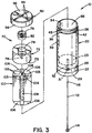
FIG. 3 is a partially-cutaway, expanded view of the cartridge ofFIG. 1 ; -
FIG. 4 is a cutaway side view of a discharge assembly; -
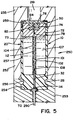
FIG. 5 is a cutaway side view of a firing chamber showing an unspent cartridge; and -
FIG. 6 is a cutaway side view of a firing chamber showing a spent cartridge. - Embodiments of the present invention are directed to a cartridge for the rapid generation of hydrogen from a first reactant that contains hydrogen and a second reactant that contains metal. The reaction can be initiated by a low electrical voltage and consumes at least some of the structure required to position the reactants such that they are sufficiently close to each other and to an igniter for the rapid reaction to be initiated by the igniter.
- Referring to
FIGs. 1-3 and6 , in accordance with an embodiment of the invention, acartridge 10 for generating hydrogen includes acase 20 configured to receive acap 50, anignition assembly 70, and aspacer 100. Thecartridge 10 is configured to be received in areaction assembly 200 and discharged therein to generate hydrogen. - As shown in
FIGs. 1, 2 , and3 ;cartridge 10 includes a generally cup-shapedcase 20 having aclosed end 22. Acircumferential groove 28 is defined aroundcase 20 atclosed end 22 andgroove 28 is spaced-away from anouter surface 29 ofclosed end 22.Closed end 22 is shaped such thatouter surface 29 defines arecess 31.Closed end 22 also defines aninner surface 23. -
Case 20 includes awall 24 that extends away fromclosed end 22 toward anopen end 26 and defining aninner surface 34.Surface 34 andsurface 23 define a cup-shapedcavity 66. Afirst passageway 32 is defined through theclosed end 22 ofcase 20 such that it extends fromrecess 31 toinner surface 23 thereby connectingouter surface 29 with cup-shapedcavity 66. Ashoulder 38 that extends from anouter surface 39 ofwall 24 to aland area 42 is defined bywall 24. Additionally, alip 43 is formed bywall 24 atopen end 26 ofcase 20. When positioned in afiring chamber 250 as shown inFIG. 4 ,wall 24 ofcase 20 is configured to deform such that a low pressure seal is formed at a predetermined pressure withincavity 66 as will be discussed further below regardingcap 50. - In the illustrated embodiment,
case 20 is formed of a thermoplastic material. By way of example and not limitation,case 20 can be formed of one of the following: nitrocellulose, cellulose, metal, metallic material, thermoplastic, or a combination thereof. By way of example and not limitation, the thermoplastic can include polycarbonate (commercially known by various trade names including Lexan®), polyoxymethylene (commercially known by various trade names including Delrin®), polymethyl methacrylate (commercially known by various trade names including Plexiglas®), and a combination thereof. - Continuing to refer to
FIGs. 1, 2 , and3 ;cap 50 includes a generallycircular wall 52 that defines aninner surface 54 and anouter surface 56.Cap 50 is positioned across theopen end 26 of cup-shapedcase 20 such thatcavity 66 is enclosed. Aflange 58 is positioned around the circumference ofwall 52 ofcap 50 and extends away frominner surface 54 ofwall 52.Flange 58 has acircumferential recess 62 formed therein that is configured to engagelip 43 ofcase 20, and thus be retained onopen end 26 ofcase 20. As can be seen inFIG. 1 , a plurality ofgrooves 64 are formed on theouter surface 54 ofcap 50. In the illustrated embodiment,grooves 64 are positioned to form a cross-shaped pattern, but it should be appreciated that in other embodiments,grooves 64 can have other configurations. -
Grooves 64 ofcap 50 are dimensioned to fail at a predetermined rupture pressure. The rupture pressure is less than a peak, i.e. maximum, pressure generated withincavity 66 by the reaction of the metallic first reactant and the oxidizing second reactant incartridge 10 in firingchamber 250. Thus cap 50 is configured as a burst disk such thatcap 50 is configured to preferentially rupture to form anopening 51 inwall 52 as shown inFIG. 6 .Opening 51 is configured to fluidly connectcavity 66 with a region outside ofcartridge 10. - Preferably, the rupture pressure is between about 34,5 bar (500 psi) and about 1034,2 bar (15,000 psi); more preferably, the rupture pressure is between about 206,8 bar (3000 psi) and about 896,3 bar (13,000 psi); and even more preferably, the rupture pressure is between about 620,5 bar (9,000 psi) and about 758,4 bar (11,000 psi). As shown in
FIG. 6 , a least onepetal 65 is formed whencap 50 ruptures alonggrooves 64. Preferably,petal 65 remains attached toflange 58 andflange 58 remains engaged withcase 20. In this manner, the components ofcap 50 that remain after discharge ofcartridge 10 are retained oncase 20 and can be recycled or disposed of along withcase 20. - In the illustrated embodiment,
cap 50 is formed of a metal. By way of example and not limitation, cap 50 can include at least one of the following: stainless steel, brass, nitrocellulose, a fiber reinforced resin, electrically conductive elements, and a combination thereof. - As shown in
FIG. 3 ,spacer 100 is positioned withincavity 66. In the illustrated embodiment,spacer 100 is generally longitudinal and has a plurality ofribs 103 that are distributed radially around acentral core 104. Apassageway 108 is formed throughcore 104 ofspacer 100. Eachrib 103 extends towardinner surface 34 ofwall 24 such that a plurality ofchambers 106 are defined byribs 103,inner surface 34 ofwall 24 andclosed end 22, and thebase surface 73 ofprimary ignition block 72. The plurality ofchambers 106 are radially disposed and are configured to receive water as an oxidizing agent such aswater 107. Alternatively,spacer 100 can be configured as cylinder that defines a central chamber or a cylinder that defines a first central chamber and a second annular chamber. In further alternatives,wall 24 includes radially disposed ribs that extend intocavity 66 and there is nospacer 100. In this embodiment, path P is formed along one of the radially disposed ribs. - In the illustrated embodiment,
spacer 100 includes ametallic particulate 101 that is embedded in amatrix 102 as can be seen inFIG. 5 .Metallic particulate 101 includes the metal first reactant.Matrix 102 is formed of a binding agent and is configured to be substantially impermeable to the oxidizing second reactant such themetallic particulate 101, and thus the metal first reactant, is substantially isolated from thewater 107. In addition,matrix 102 is consumable during the rapid reaction of the metal first reactant and the oxidizing second reactant as discussed further below. As used herein, the term "consumable" refers to the quality of changing form or reacting such that themetallic particulate 101, and thus the metal first reactant, is substantially no longer isolated fromwater 107. - In this regard,
matrix 102 is configured to limit unintended reactions betweenwater 107 and metallic particulate 101 such that no additional barrier between the metallic portion ofspacer 100 andwater 107 is required. Thus manufacture ofcartridge 10 relative to conventional systems is simplified in that no separate container is required forwater 107. Themetallic particulate 101 ofspacer 100 can include as the first metal reactant metals such as aluminum, magnesium, iron, sodium, potassium, titanium, and combinations thereof. In the illustrated embodiment,metallic particulate 101 includes aluminum and it is believed that aluminum having any purity is suitable for use as the reactive metal, and therefore, any alloy of aluminum is suitable for use as a metallic insert of the present invention. By way of example and not limitation, in alternative embodiments spacer 100 can include one of the following metallic materials: a woven metal mesh, a metal wool, discrete metal pellets, and a combination thereof. In these alternative embodiments, the metallic material is coated with the binding agent. - The
matrix 102 is a material that can function to bindmetallic particulate 101 together. Other desirable characteristics of the matrix are: it is soluble and when solvated can be mixed withparticulate 101, it can be easily dried or cured to form the desired component ofcartridge 10, and it is consumable during a rapid reaction between the metal first reactant and the oxidizing second reactant. In the illustrated embodiment, the matrix includes nitrocellulose. By way of example and not limitation, the matrix can include one of the following: nitrocellulose, dextrin, guar gum, gum Arabic, shellac, synthetic organic polymers, other organic materials, and a combination thereof. In the illustrated embodiment, the percentage of metallic particulate 101 relative to the combined weight ofmetal particulate 101 andmatrix 102 inspacer 100 is preferably between about 80% and about 99.9%; more preferably between about 88% and 98%; and most preferably between about 92% and 96%. It should be appreciated that structures other thanspacer 100 disclosed herein that are formed of metallic particulate 101 embedded inmatrix 102 have substantially similar compositions to that ofspacer 100. - It should be appreciated that the water can be pure or can contain various contaminates such as salts, metals, minerals, etc. The water can be a liquid or substantially solidified by combination with a gelatinizing agent. The ratio of the metallic first reactant, for example aluminum, and the oxidizing agent water is generally equal to the stoichiometric ratio of the oxidizing reaction between the two components. Therefore, when the metallic first reactant is aluminum and the oxidizing second reactant is water, the stoichiometric ratio is about one to one, and aluminum and water are contained in
cartridge 10 in a ratio of about one to one. Referring tometal particles 101, they are provided such that the reactive metal contained therein is in an appropriate ratio. For example, ifmetal particles 101 are essentially pure aluminum, the mass ofmetallic particles 101 contained within thecartridge 10 is generally equal to the mass ofwater 107 incartridge 10. Likewise, ifmetallic particles 101 include fifty percent by weight of nonreactive contaminants, then the mass ofmetallic particles 101 contained withincartridge 10 is generally two times the mass ofwater 107 incartridge 10. -
Spacer 100 is configured to positionignition assembly 70 withincavity 66 such thatassembly 70 is nearcap 50 and in this regard,spacer 100 is a structural component. Inalternative embodiments wall 24 ofcase 20 includes tabs or ribs that are configured to positionignition assembly 70 withincavity 66.Spacer 100 is configured to extend withincavity 66 fromclosed end 22 toassembly 70. Such that one end ofspacer 100 is nearsurface 23 and another end ofspacer 100 is nearsurface 73. It should be appreciated that whilespacer 100 is configured to mechanicallyseparate assembly 70 fromclosed end 22, in some embodiments spacer 100 is movable relatively one or both ofassembly 70 andclosed end 22, and in addition, might not be in direct contact with one or both ofassembly 70 andclosed end 22. -
Ignition assembly 70 is configured as an igniter and includes aprimary ignition block 72 having arecess 74 formed therein. As used herein, the term "igniter" refers to a structure configured to generate sufficient temperature to initiate, i.e. ignite, a reaction between reactants. Apassageway 78 is defined fromrecess 74 through a base portion ofprimary ignition block 72 to abase surface 73 defined by the base portion ofprimary ignition block 72.Recess 74 is dimensioned to receive apre-ignition block 76. In the illustrated embodiment, bothprimary ignition block 72 andpre-ignition block 76 are generally cylindrical. -
Primary ignition block 72 includes thermite. As used herein, the term "thermite" refers to a composition that includes a metal oxide that acts as an oxidizing agent and a metal to be oxidized by the oxidizing agent. By way of example and not limitation, the metal oxide can be black or blue iron oxide (Fe3O4), red iron(III) oxide (Fe2O3), manganese oxide (MnO2), Chromium (III) oxide Cr2O3, cuprous oxide (Cu2O), cupric oxide, (copper (II) oxide, CuO), other metal oxide, or a combination thereof. The metal to be oxidized can be aluminum or other reactive metal. - In one embodiment, the metal oxide is iron oxide (Fe3O4). Preferably, the thermite is formed together with a binding agent into a desired shape and the binding agent is a nitrocellulose lacquer. In this regard, the particles of thermite are retained within a matrix of nitrocellulose. It should be appreciated that in another embodiment, the
primary ignition block 72 is formed of thermite that is configured to retain its shape without a binder, i.e. compressed or solid thermite. In a further alternate embodiment, the thermite can be in the form of particles that are retained in a container or wrapping (not shown) that is configured to support and shapeprimary ignition block 72. -
Pre-ignition block 76 is formed of a pre-ignition compound that includes potassium perchlorate, magnesium, and aluminum.Pre-ignition block 76 includes anelement 82.Element 82 is configured to electrically connectcap 50 with a region adjacent one end ofpassageway 78 ofprimary ignition block 72. It should be appreciated thatelement 82 can be any electrical element configured to generate heat when exposed to an electrical differential. In oneembodiment element 82 is a bridge wire. As used herein, the term "bridge wire" refers to a relatively thin resistance wire used to ignite a pyrotechnic composition. -
Pre-ignition block 76 is formed by a molding process in which the pre-ignition compound is formed of particles that are mixed with a binding agent and molded to a desired shape. The binding agent can be a lacquer such as nitrocellulose lacquer and in such an embodiment,pre-ignition block 76 is formed of particles of the pre-ignition compound embedded in a matrix of nitrocellulose. In the illustrated embodiment, the mixture of binding agent and pre-ignition compound is molded aroundelement 82 such thatelement 82 is also embedded in the matrix of nitrocellulose. It should be appreciated that in other embodiments,pre-ignition block 76 can include solid or particulate components and can be positioned within a container or wrapping (not shown) that is configured to support and shapepre-ignition block 76. Further,element 82 can be positioned aroundpre-ignition block 76 or through a passageway formed therein after initial shaping of the pre-ignition block is complete. -
Pre-ignition block 76 is configured to ignite whenelement 82 is exposed to an electrical voltage differential that is preferably between about 1 volts and about 100 volts, more preferably between about 5 volts and about 30 volts, and even more preferably between about 10 volts and about 15 volts, and most preferably about 12 volts. -
Pre-ignition block 76 is configured to generate a temperature upon ignition that is sufficient to igniteprimary ignition block 72.Primary ignition block 72 is configured to generate a temperature after ignition that is sufficient to initiate an oxidation reaction between the metal first reactant, and the oxidizing second reactant. In other embodiments, the ignition ofcomposition 72 is sufficient to initiate a similar oxidation reaction that generates hydrogen.Primary ignition block 72 is configured to generate a temperature that is between 1371 °C (2,500 degrees Farenheit) and 3316°C (6,000 degrees Farenheit), more preferably between about 1788°C (3,250 degrees Farenheit) and about 2760°C (5,000 degrees Farenheit), and even more preferably between about 1927 °C (3,500 degrees Farenheit) and about 2482 °C (4,500 degrees Farenheit).Ignition assembly 70 is configured to initiate a reaction betweenspacer 100 and water as will be discussed further below. - As shown in
FIGs. 2 and3 ,passageway 32 ofclosed end 22,passageway 108 ofspacer 100, andpassageway 78 ofprimary ignition block 72, are aligned to form a continuous primary passageway that connectsouter surface 29 ofclosed end 22 withelement 82. The primary passageway is configured to receive aconductor 112 that is configured toelectrically contact element 82 at anend 116 such thatelement 82 is electrically connected with abutton 114.Conductor 112 is also configured to be electrically insulated from other components ofcartridge 10. By way of example and not limitation,conductor 112 includes one of the following: a solid metal wire, stranded metal wire, aluminum, silver, other metal, carbon, other conductive non-metal, and a combination thereof. In oneembodiment conductor 112 is an insulated metallic wire.Button 114 is configured to provide a surface for electrical contact that is positioned exterior ofcartridge 10, andbutton 114 is configured to be received inaxial recess 31 ofclosed end 22. By way of example and not limitation,button 114 includes one of the following: aluminum, silver, other metal, carbon, other conductive non-metal, and a combination thereof. - In this manner, an electrically conductive path P is formed that extends from
outer surface 29 ofclosed end 22 toouter surface 56 ofcap 50. Path P is configured to conduct an electric current such that thepre-ignition block 76 can be ignited as will be discussed below with regard to the operation of the present invention. - Referring now to
FIG. 4 ,cartridge 10 is configured to be received by areaction assembly 200 and activated therein.Reaction assembly 200 includes ahydrogen containment vessel 204, amagazine 240, aloading device 241 and afiring chamber 250.Containment vessel 204 has awall 205 that defines acavity 206. Apressure sensor 208 is fluidly connected throughwall 205 tocavity 206. In the illustrated embodiment,pressure sensor 208 is configured to generate a signal indicative of the pressure withincavity 206 and includes an operator interface. - A
discharge tube 214 defines a passageway that fluidly connectscavity 206 with a device or region outside ofreaction assembly 200. Acontrol valve 212 positioned indischarge tube 214 and is configured to control the flow of fluid throughdischarge tube 214. In one embodiment,control valve 212 is a pressure regulator valve that is configured to maintain a predetermined pressure withincavity 206. Avalve 216 is positioned onwall 205 and is configured to ventcavity 206 to the region outside ofvessel 204 at a predetermined pressure, i.e.,valve 216 is configured as a pressure relief valve. - A
flow control mechanism 251 is positioned between firingchamber 250 andvessel 204.Mechanism 251 is configured to provide for the discharge of gas from firingchamber 250 intocavity 206.Mechanism 251 is also configured to prevent flow of gas fromcavity 206 into firingchamber 250.Flow control mechanism 251 is electrically connected tocontroller 290 and is configured to be actuated bycontroller 290. - Continuing to refer to
FIG. 4 ,magazine 240 is configured to supply a plurality ofcartridges 10 to firingchamber 250 via aloading device 241.Loading device 241 is positioned betweenmagazine 240 and firingchamber 250 and is configured to convey acartridge 10 frommagazine 240 to firingchamber 250. In the illustrated embodiment,magazine 240 is detachable from the remainder of firingassembly 200. It should be appreciated that a plurality ofmagazines 240 are interchangeable such thatsubsequent magazines 240 can replace aninitial magazine 240 and in this manner a supply ofcartridges 10 can be provided to firingassembly 200 and more specifically to firingchamber 250. - Firing
chamber 250 is best seen inFIG. 5 and includes abreech block 253 and a generallytubular chamber wall 252. Breech block 253 definesinterior tabs 256 that are configured to engagecircumferential groove 28 ofcartridge 10. Breech block 253 is configured to be openable such thatcartridge 10 can be received therein. - Breech block 253 of firing
chamber 250 is generally cup-shaped and includes aback wall 254. Generallytubular sidewall 252 that extends away frombreech block 253 toward anopen end 255.Sidewall 252 andbreech block 253 define abore 257 that is configured to receive acartridge 10.Wall 252 defines ashoulder 259 that separates athroat 261 frombore 257.Throat 261 has a diameter nearshoulder 259 that is smaller than the diameter ofbore 257. In one embodiment,throat 261 is generally cylindrical. Firingchamber 250 is positioned such thatopen end 255 is adjacentflow control mechanism 251 such that gases can be directed throughthroat 261 intoflow control mechanism 251. - Breech block 253 is configured to provide for the conveyance of
cartridge 10 fromloading device 241 intobore 257 of firingchamber 250. Whencartridge 10 has been loaded intobore 257,tabs 256 engagecircumferential groove 28 ofcartridge 10 such thatcartridge 10 is securely positioned within firingchamber 250. As can be seen inFIG. 6 , firingchamber 250 is positioned such that solid residue andwaste 67 generated during a discharge ofcartridge 10 is retained withinbore 257, and in the illustrated embodiment,cavity 66 ofcartridge 10. In this regard, firingchamber 250 is oriented such thatopen end 255 is positioned aboveback wall 254, and more specifically, firingchamber 250 is oriented substantially vertically such thatopen end 255 is generally overback wall 254. It should be appreciated that alternatively,discharge system 200 can be configured such that firingchamber 250 is in motion during a discharge ofcartridge 10 and that such motion creates a force directed towardback wall 254 such that solids are retained withincavity 66. In such anembodiment cartridge 10 can be operated generally without regard to the strength and direction of gravitational forces. - In the illustrated embodiment,
breech block 253 includes acontact 258 that is positioned centrally relative to backwall 254 and is electrically isolated from firingchamber 250. Contact 258 is configured to electrically engagebutton 114 ofcartridge 10 whencartridge 10 is positioned withinbore 257. Contact 258 is electrically connected tocontroller 290 such thatcontact 258 can form part of an electrical circuit that includes electrical path P ofcartridge 10. - In this regard,
breech block 253 andtubular sidewalls 252 are formed of an electrically conductive material. When acartridge 10 is positioned withinbore 257 andbreech block 253 is in the closed position, electricallyconductive button 114 ofcartridge 10 is electrically connected to contact 258 and cap 50 ofcartridge 10 is in electrical contact withtubular sidewalls 252 of firingchamber 250. In this manner, an electrical circuit is formed that electrically connectstubular side wall 252 andbreech block 252 via electrical path P described above. - Continuing to refer to
FIG. 6 , after acartridge 10 is discharged a spent cartridge 10' remains. Some components of spent cartridge 10' are analogous to components ofcartridge 10 and will be designated by identical reference numbers and the prime symbol. In this regard, spent cartridge 10' includes a case 20', a button 114', a cavity 66', and a cap 50'. These components of spent cartridge 10' can be generally understood from the foregoing descriptions of the corresponding components ofcartridge 10. - In the illustrated embodiment,
controller 290 is configured to control the electrical connection betweencontact 258 and a voltage source (not shown). In this manner,controller 290 is configured to control the discharge ofcartridge 10. As used herein, the term "discharge" refers to the reaction of the contents ofcartridge 10 to form hydrogen such that hydrogen passes throughopening 51. Further,loading device 241, contact 258 of firingchamber 250,pressure sensor 208 andvalve 212 are electrically connected to acontroller 290.Controller 290 is configured to activateloading device 241, firingchamber 250, andvalve 212 based upon predetermined parameters or instructions input by an operator. In one embodiment,controller 290 is an electronic computer that includes a storage device and a data input device. - In another alternate embodiment, a mechanical firing device such as a percussion cap (not shown) is utilized to ignite the
pre-ignition block 76 instead ofelement 82. - In an alternative embodiment,
case 20 is formed of ametallic particulate 101 embedded in amatrix 102 as described with regard tospacer 100 above. In this embodiment, the total amount of a reactive metal in thecartridge 10 is in stoichiometric proportions to the total amount ofwater 107 as it is in the illustrated embodiment. Therefore spacer 100 would contain less aluminum in this embodiment than in the illustrated embodiment wherein the mass of aluminum contained inspacer 100 is generally equal to the mass ofwater 107. - It should be appreciated that nitrocellulose is consumed by the reaction. Therefore structures formed from nitrocellulose and the metal first reactant in various embodiments, such as
spacer 100 orcase 20, are consumed by the reaction between aluminum and water to generate hydrogen. It is believed that consumption of the matrix generates a relative small amount of waste in either a solid or a gas. - The present invention can be better understood in light of the following description of the operation thereof. In the illustrated embodiment,
cartridge 10 is configured to generate hydrogen by the reaction ofspacer 100 with water contained withincavity 106. According to a method provided by the present invention, acartridge 10 is positioned within firingchamber 250. A voltage is applied bycontroller 290 to contact 258 such that an electrical current flows frombutton 114, alongconductor 112, throughelement 82, throughcap 50, throughsidewalls 252, and to the electrical ground. The current is sufficient to ignitepre-ignition block 76 and thus assembly 70 such thatspacer 100 and the water in thecavities 106 are raised to a temperature sufficient to initiate an oxidation reaction between thespacer 100 andwater 107. - The principle products of this reaction are hydrogen gas and a metallic oxide. Pressures generated within
cavity 66 are sufficient to rupturecap 50 andform opening 51. It is believed that a substantial portion of solid reaction products such as metal oxide and other solids generated by the discharge ofcartridge 10 remain withincavity 66 or attached tocase 20. Hydrogen gas passes fromcavity 66 throughopening 51 andflow control mechanism 251 intocavity 206 ofcontainment vessel 204. The quantity of hydrogen gas and temperature of the hydrogen gas discharged fromcartridge 10 determines the pressure withincavity 206.Valve 212, shown inFIG. 4 , operates to provide for the discharge of hydrogen gas fromcavity 206.Additional cartridges 10 can be discharged to generate additional hydrogen gas such that the pressure withcavity 206 is maintained at a predetermined level. In thismanner cavity 206 acts as a reservoir configured to provide a continuous supply of hydrogen gas to a device configured to consume the hydrogen. It is believed that operation of the present invention can provide a source of high pressure hydrogen. - In all embodiments,
spacer 10 is configured such that sufficient quantities ofmetallic particulate 101 and oxidizing agent, such aswater 107, are positioned such a rapid reaction between metallic particulate 101 and the oxidizing agent can be initiated byassembly 70. Once the rapid hydrogen generating reaction has begun, it is believed that it will continue until one or both reactants are consumed. In this regard, it is believed that the reaction will continue until substantially all of themetallic particulate 101 and that all components ofcartridge 10 that were formed of the reactive metal will be consumed during the rapid generation of hydrogen. - The present invention applies generally to cartridges for the formation of hydrogen. More specifically, a reusable or expendable cartridge is provided for the on-demand and nearly instantaneous generation of hydrogen at high temperatures and at high pressures. While the present invention has been illustrated and described with reference to preferred embodiments thereof, it will be apparent to those skilled in the art that modifications can be made and the Invention can be practiced in other environments without departing from the scope of the invention, set forth in the accompanying claims.
Claims (9)
- A cartridge for the generation of hydrogen, the cartridge comprising:a case that defines an interior cavity;an igniter positioned within the cavity;a structural component positioned within the cavity, the structural component being formed of a particulate embedded in a matrix and the particulate includes a metallic material; andan oxidizing agent positioned within the cavity, wherein the oxidizing agent is water,wherein the matrix of the structural component includes at least one member selected from the group consisting of nitrocellulose, dextrin, guar gum, gum Arabic, shellac, and synthetic organic polymers, and is configured to be impermeable to water so that the metallic material is isolated from the water, andwherein the igniter is configured to generate a temperature that is between 1371°C (2,500 degrees Fahrenheit) and 3316°C (6,000 degrees Fahrenheit) so as to remove the matrix from the structural component such that the metallic material is no longer isolated from water and to initiate a reaction between the metallic material and the oxidizing agent to generate hydrogen.
- A cartridge according to claim 1, wherein the structural component is configured to generally maintain the position of the igniter relative to the case.
- A cartridge according to claim 2, wherein the matrix includes nitrocellulose.
- A cartridge according to claim 3, wherein the case is also formed of the particulate embedded in the matrix.
- A cartridge according to claim 4, wherein the igniter includes thermite.
- A cartridge according to claim 1, wherein the water is gelatinized.
- A cartridge according to claim 1, wherein the metallic material includes aluminum.
- A cartridge according to claim 1, wherein an electrical element is positioned within the igniter and is electrically connected with an exterior surface of the case.
- A cartridge according to claim 8, wherein the igniter is configured to ignite when a voltage is applied to the electrical element.
Priority Applications (1)
| Application Number | Priority Date | Filing Date | Title |
|---|---|---|---|
| PL10751253T PL2406174T3 (en) | 2009-03-11 | 2010-03-09 | Cartridge for the generation of hydrogen |
Applications Claiming Priority (2)
| Application Number | Priority Date | Filing Date | Title |
|---|---|---|---|
| US12/401,651 US7967879B2 (en) | 2009-03-11 | 2009-03-11 | Cartridge for the generation of hydrogen |
| PCT/US2010/026585 WO2010104807A1 (en) | 2009-03-11 | 2010-03-09 | Cartridge for the generation of hydrogen |
Publications (3)
| Publication Number | Publication Date |
|---|---|
| EP2406174A1 EP2406174A1 (en) | 2012-01-18 |
| EP2406174A4 EP2406174A4 (en) | 2013-12-25 |
| EP2406174B1 true EP2406174B1 (en) | 2020-08-05 |
Family
ID=42728692
Family Applications (1)
| Application Number | Title | Priority Date | Filing Date |
|---|---|---|---|
| EP10751253.5A Not-in-force EP2406174B1 (en) | 2009-03-11 | 2010-03-09 | Cartridge for the generation of hydrogen |
Country Status (4)
| Country | Link |
|---|---|
| US (1) | US7967879B2 (en) |
| EP (1) | EP2406174B1 (en) |
| PL (1) | PL2406174T3 (en) |
| WO (1) | WO2010104807A1 (en) |
Families Citing this family (1)
| Publication number | Priority date | Publication date | Assignee | Title |
|---|---|---|---|---|
| GB201621497D0 (en) | 2016-12-16 | 2017-02-01 | Blacktrace Holdings Ltd | A seal assembly for creating a sealed flow path between first and second fluid ducts |
Family Cites Families (14)
| Publication number | Priority date | Publication date | Assignee | Title |
|---|---|---|---|---|
| US4000022A (en) | 1974-10-17 | 1976-12-28 | The United States Of America As Represented By The Secretary Of The Navy | Fast-burning compositions of fluorinated polymers and metal powders |
| US5012719A (en) | 1987-06-12 | 1991-05-07 | Gt-Devices | Method of and apparatus for generating hydrogen and projectile accelerating apparatus and method incorporating same |
| US5052272A (en) | 1990-08-06 | 1991-10-01 | The United States Of America As Represented By The Secretary Of The Navy | Launching projectiles with hydrogen gas generated from aluminum fuel powder/water reactions |
| US5143047A (en) * | 1991-06-20 | 1992-09-01 | The United States Of America As Represented By The Secretary Of The Navy | Material and method for fast generation of hydrogen gas and steam |
| US5634341A (en) | 1994-01-31 | 1997-06-03 | The Penn State Research Foundation | System for generating hydrogen |
| US6849247B1 (en) * | 2002-07-10 | 2005-02-01 | The United States Of America As Represented By The Secretary Of The Navy | Gas generating process for propulsion and hydrogen production |
| US7052658B2 (en) | 2003-01-29 | 2006-05-30 | Hewlett-Packard Development Company, Lp. | Hydrogen generation cartridge and portable hydrogen generator |
| US6989210B2 (en) | 2003-04-23 | 2006-01-24 | Hewlett-Packard Development Company, L.P. | Fuel cartridge with thermo-degradable barrier system |
| US7402777B2 (en) | 2004-05-20 | 2008-07-22 | Alexza Pharmaceuticals, Inc. | Stable initiator compositions and igniters |
| US7678479B2 (en) | 2004-11-29 | 2010-03-16 | Angstrom Power Incorporated | Hydrogen fuel delivery systems |
| JP2006248814A (en) | 2005-03-09 | 2006-09-21 | Hitachi Ltd | Hydrogen supply apparatus and hydrogen supply method |
| US20060210470A1 (en) * | 2005-03-18 | 2006-09-21 | Purdue Research Foundation | System and method for generating hydrogen |
| US20070068521A1 (en) | 2005-09-27 | 2007-03-29 | Treatyou Medical Technology Co., | Portable oxygen generating system and method of using the same |
| JP5383989B2 (en) * | 2007-08-29 | 2014-01-08 | 独立行政法人科学技術振興機構 | Hydrogen gas generating member and method for producing hydrogen gas |
-
2009
- 2009-03-11 US US12/401,651 patent/US7967879B2/en active Active - Reinstated
-
2010
- 2010-03-09 WO PCT/US2010/026585 patent/WO2010104807A1/en not_active Ceased
- 2010-03-09 PL PL10751253T patent/PL2406174T3/en unknown
- 2010-03-09 EP EP10751253.5A patent/EP2406174B1/en not_active Not-in-force
Non-Patent Citations (1)
| Title |
|---|
| None * |
Also Published As
| Publication number | Publication date |
|---|---|
| EP2406174A1 (en) | 2012-01-18 |
| US20100233043A1 (en) | 2010-09-16 |
| WO2010104807A1 (en) | 2010-09-16 |
| EP2406174A4 (en) | 2013-12-25 |
| PL2406174T3 (en) | 2021-01-25 |
| US7967879B2 (en) | 2011-06-28 |
Similar Documents
| Publication | Publication Date | Title |
|---|---|---|
| CA2420763C (en) | Portable hydrogen source | |
| US6085516A (en) | Hybrid rocket system and integrated motor for use therein | |
| CA2689991C (en) | Cartridge ammunition, particularly blank ammunition | |
| US6016652A (en) | Hybrid rocket system with disposable cartridge | |
| WO1992003394A1 (en) | Water reactive device and method | |
| GB1593677A (en) | Propellant charge igniter | |
| US7574960B1 (en) | Ignition element | |
| JP2009184840A (en) | Hydrogen generator and fuel pellet body | |
| US20080035252A1 (en) | Solid hydrogen fuel elements and methods of making the same | |
| US7051655B1 (en) | Low-energy optical detonator | |
| US7967879B2 (en) | Cartridge for the generation of hydrogen | |
| US8499997B2 (en) | Cartridge for the generation of hydrogen for bonding materials | |
| US8578718B2 (en) | Cartridge for the generation of hydrogen for providing mechanical power | |
| US7117796B1 (en) | Igniter for exothermic torch rod | |
| GB1585221A (en) | Igniter for a block of combustible powder | |
| US3267672A (en) | Gas generating device with initiator insulating means | |
| Koch | Special materials in pyrotechnics VII: Pyrotechnics used in thermal batteries | |
| WO2009116593A1 (en) | Hydrogen generator | |
| US20050132922A1 (en) | Gun ammunition | |
| CN110953934B (en) | A kind of high temperature resistant inductive electric explosion tube and charging sequence | |
| EP4515166A1 (en) | Delay ignitor cap, blowback ignitor cap, and combination ignitor cap for a thermal lance and thermal lances including such ignitor caps | |
| US20220216541A1 (en) | Metal-oxygen primary reserve batteries with integrated oxygen generator for munitions and the like applications | |
| US20050029717A1 (en) | Igniter for oxygen lance for thermal cutting, drilling etc. | |
| KR19980703195A (en) | Electrothermal chemical cartridge | |
| Press et al. | Thermal batteries, their technologies and applications |
Legal Events
| Date | Code | Title | Description |
|---|---|---|---|
| PUAI | Public reference made under article 153(3) epc to a published international application that has entered the european phase |
Free format text: ORIGINAL CODE: 0009012 |
|
| 17P | Request for examination filed |
Effective date: 20110922 |
|
| AK | Designated contracting states |
Kind code of ref document: A1 Designated state(s): AT BE BG CH CY CZ DE DK EE ES FI FR GB GR HR HU IE IS IT LI LT LU LV MC MK MT NL NO PL PT RO SE SI SK SM TR |
|
| DAX | Request for extension of the european patent (deleted) | ||
| A4 | Supplementary search report drawn up and despatched |
Effective date: 20131127 |
|
| RIC1 | Information provided on ipc code assigned before grant |
Ipc: C01B 3/08 20060101AFI20131121BHEP Ipc: C01B 3/10 20060101ALI20131121BHEP Ipc: F24J 1/00 20060101ALI20131121BHEP |
|
| STAA | Information on the status of an ep patent application or granted ep patent |
Free format text: STATUS: EXAMINATION IS IN PROGRESS |
|
| 17Q | First examination report despatched |
Effective date: 20170529 |
|
| REG | Reference to a national code |
Ref country code: DE Ref legal event code: R079 Ref document number: 602010065100 Country of ref document: DE Free format text: PREVIOUS MAIN CLASS: C01B0003000000 Ipc: C01B0003080000 |
|
| GRAP | Despatch of communication of intention to grant a patent |
Free format text: ORIGINAL CODE: EPIDOSNIGR1 |
|
| STAA | Information on the status of an ep patent application or granted ep patent |
Free format text: STATUS: GRANT OF PATENT IS INTENDED |
|
| RIC1 | Information provided on ipc code assigned before grant |
Ipc: C01B 3/10 20060101ALI20200212BHEP Ipc: C01B 3/08 20060101AFI20200212BHEP |
|
| INTG | Intention to grant announced |
Effective date: 20200318 |
|
| GRAS | Grant fee paid |
Free format text: ORIGINAL CODE: EPIDOSNIGR3 |
|
| GRAA | (expected) grant |
Free format text: ORIGINAL CODE: 0009210 |
|
| STAA | Information on the status of an ep patent application or granted ep patent |
Free format text: STATUS: THE PATENT HAS BEEN GRANTED |
|
| AK | Designated contracting states |
Kind code of ref document: B1 Designated state(s): AT BE BG CH CY CZ DE DK EE ES FI FR GB GR HR HU IE IS IT LI LT LU LV MC MK MT NL NO PL PT RO SE SI SK SM TR |
|
| REG | Reference to a national code |
Ref country code: GB Ref legal event code: FG4D |
|
| REG | Reference to a national code |
Ref country code: CH Ref legal event code: EP |
|
| REG | Reference to a national code |
Ref country code: AT Ref legal event code: REF Ref document number: 1298467 Country of ref document: AT Kind code of ref document: T Effective date: 20200815 |
|
| REG | Reference to a national code |
Ref country code: DE Ref legal event code: R096 Ref document number: 602010065100 Country of ref document: DE |
|
| REG | Reference to a national code |
Ref country code: IE Ref legal event code: FG4D |
|
| REG | Reference to a national code |
Ref country code: SE Ref legal event code: TRGR |
|
| REG | Reference to a national code |
Ref country code: LT Ref legal event code: MG4D |
|
| REG | Reference to a national code |
Ref country code: NL Ref legal event code: MP Effective date: 20200805 |
|
| REG | Reference to a national code |
Ref country code: AT Ref legal event code: MK05 Ref document number: 1298467 Country of ref document: AT Kind code of ref document: T Effective date: 20200805 |
|
| PG25 | Lapsed in a contracting state [announced via postgrant information from national office to epo] |
Ref country code: HR Free format text: LAPSE BECAUSE OF FAILURE TO SUBMIT A TRANSLATION OF THE DESCRIPTION OR TO PAY THE FEE WITHIN THE PRESCRIBED TIME-LIMIT Effective date: 20200805 Ref country code: LT Free format text: LAPSE BECAUSE OF FAILURE TO SUBMIT A TRANSLATION OF THE DESCRIPTION OR TO PAY THE FEE WITHIN THE PRESCRIBED TIME-LIMIT Effective date: 20200805 Ref country code: BG Free format text: LAPSE BECAUSE OF FAILURE TO SUBMIT A TRANSLATION OF THE DESCRIPTION OR TO PAY THE FEE WITHIN THE PRESCRIBED TIME-LIMIT Effective date: 20201105 Ref country code: ES Free format text: LAPSE BECAUSE OF FAILURE TO SUBMIT A TRANSLATION OF THE DESCRIPTION OR TO PAY THE FEE WITHIN THE PRESCRIBED TIME-LIMIT Effective date: 20200805 Ref country code: PT Free format text: LAPSE BECAUSE OF FAILURE TO SUBMIT A TRANSLATION OF THE DESCRIPTION OR TO PAY THE FEE WITHIN THE PRESCRIBED TIME-LIMIT Effective date: 20201207 Ref country code: FI Free format text: LAPSE BECAUSE OF FAILURE TO SUBMIT A TRANSLATION OF THE DESCRIPTION OR TO PAY THE FEE WITHIN THE PRESCRIBED TIME-LIMIT Effective date: 20200805 Ref country code: GR Free format text: LAPSE BECAUSE OF FAILURE TO SUBMIT A TRANSLATION OF THE DESCRIPTION OR TO PAY THE FEE WITHIN THE PRESCRIBED TIME-LIMIT Effective date: 20201106 Ref country code: AT Free format text: LAPSE BECAUSE OF FAILURE TO SUBMIT A TRANSLATION OF THE DESCRIPTION OR TO PAY THE FEE WITHIN THE PRESCRIBED TIME-LIMIT Effective date: 20200805 Ref country code: NO Free format text: LAPSE BECAUSE OF FAILURE TO SUBMIT A TRANSLATION OF THE DESCRIPTION OR TO PAY THE FEE WITHIN THE PRESCRIBED TIME-LIMIT Effective date: 20201105 |
|
| PG25 | Lapsed in a contracting state [announced via postgrant information from national office to epo] |
Ref country code: NL Free format text: LAPSE BECAUSE OF FAILURE TO SUBMIT A TRANSLATION OF THE DESCRIPTION OR TO PAY THE FEE WITHIN THE PRESCRIBED TIME-LIMIT Effective date: 20200805 Ref country code: LV Free format text: LAPSE BECAUSE OF FAILURE TO SUBMIT A TRANSLATION OF THE DESCRIPTION OR TO PAY THE FEE WITHIN THE PRESCRIBED TIME-LIMIT Effective date: 20200805 Ref country code: IS Free format text: LAPSE BECAUSE OF FAILURE TO SUBMIT A TRANSLATION OF THE DESCRIPTION OR TO PAY THE FEE WITHIN THE PRESCRIBED TIME-LIMIT Effective date: 20201205 |
|
| PG25 | Lapsed in a contracting state [announced via postgrant information from national office to epo] |
Ref country code: SM Free format text: LAPSE BECAUSE OF FAILURE TO SUBMIT A TRANSLATION OF THE DESCRIPTION OR TO PAY THE FEE WITHIN THE PRESCRIBED TIME-LIMIT Effective date: 20200805 Ref country code: RO Free format text: LAPSE BECAUSE OF FAILURE TO SUBMIT A TRANSLATION OF THE DESCRIPTION OR TO PAY THE FEE WITHIN THE PRESCRIBED TIME-LIMIT Effective date: 20200805 Ref country code: DK Free format text: LAPSE BECAUSE OF FAILURE TO SUBMIT A TRANSLATION OF THE DESCRIPTION OR TO PAY THE FEE WITHIN THE PRESCRIBED TIME-LIMIT Effective date: 20200805 Ref country code: EE Free format text: LAPSE BECAUSE OF FAILURE TO SUBMIT A TRANSLATION OF THE DESCRIPTION OR TO PAY THE FEE WITHIN THE PRESCRIBED TIME-LIMIT Effective date: 20200805 |
|
| REG | Reference to a national code |
Ref country code: DE Ref legal event code: R097 Ref document number: 602010065100 Country of ref document: DE |
|
| PLBE | No opposition filed within time limit |
Free format text: ORIGINAL CODE: 0009261 |
|
| STAA | Information on the status of an ep patent application or granted ep patent |
Free format text: STATUS: NO OPPOSITION FILED WITHIN TIME LIMIT |
|
| PG25 | Lapsed in a contracting state [announced via postgrant information from national office to epo] |
Ref country code: SK Free format text: LAPSE BECAUSE OF FAILURE TO SUBMIT A TRANSLATION OF THE DESCRIPTION OR TO PAY THE FEE WITHIN THE PRESCRIBED TIME-LIMIT Effective date: 20200805 |
|
| 26N | No opposition filed |
Effective date: 20210507 |
|
| PG25 | Lapsed in a contracting state [announced via postgrant information from national office to epo] |
Ref country code: IT Free format text: LAPSE BECAUSE OF FAILURE TO SUBMIT A TRANSLATION OF THE DESCRIPTION OR TO PAY THE FEE WITHIN THE PRESCRIBED TIME-LIMIT Effective date: 20200805 |
|
| PG25 | Lapsed in a contracting state [announced via postgrant information from national office to epo] |
Ref country code: SI Free format text: LAPSE BECAUSE OF FAILURE TO SUBMIT A TRANSLATION OF THE DESCRIPTION OR TO PAY THE FEE WITHIN THE PRESCRIBED TIME-LIMIT Effective date: 20200805 |
|
| PG25 | Lapsed in a contracting state [announced via postgrant information from national office to epo] |
Ref country code: MC Free format text: LAPSE BECAUSE OF FAILURE TO SUBMIT A TRANSLATION OF THE DESCRIPTION OR TO PAY THE FEE WITHIN THE PRESCRIBED TIME-LIMIT Effective date: 20200805 |
|
| REG | Reference to a national code |
Ref country code: CH Ref legal event code: PL |
|
| REG | Reference to a national code |
Ref country code: BE Ref legal event code: MM Effective date: 20210331 |
|
| PG25 | Lapsed in a contracting state [announced via postgrant information from national office to epo] |
Ref country code: CH Free format text: LAPSE BECAUSE OF NON-PAYMENT OF DUE FEES Effective date: 20210331 Ref country code: LI Free format text: LAPSE BECAUSE OF NON-PAYMENT OF DUE FEES Effective date: 20210331 Ref country code: LU Free format text: LAPSE BECAUSE OF NON-PAYMENT OF DUE FEES Effective date: 20210309 Ref country code: IE Free format text: LAPSE BECAUSE OF NON-PAYMENT OF DUE FEES Effective date: 20210309 |
|
| PG25 | Lapsed in a contracting state [announced via postgrant information from national office to epo] |
Ref country code: BE Free format text: LAPSE BECAUSE OF NON-PAYMENT OF DUE FEES Effective date: 20210331 |
|
| PGFP | Annual fee paid to national office [announced via postgrant information from national office to epo] |
Ref country code: FR Payment date: 20230320 Year of fee payment: 14 Ref country code: CZ Payment date: 20230301 Year of fee payment: 14 |
|
| PG25 | Lapsed in a contracting state [announced via postgrant information from national office to epo] |
Ref country code: HU Free format text: LAPSE BECAUSE OF FAILURE TO SUBMIT A TRANSLATION OF THE DESCRIPTION OR TO PAY THE FEE WITHIN THE PRESCRIBED TIME-LIMIT; INVALID AB INITIO Effective date: 20100309 Ref country code: CY Free format text: LAPSE BECAUSE OF FAILURE TO SUBMIT A TRANSLATION OF THE DESCRIPTION OR TO PAY THE FEE WITHIN THE PRESCRIBED TIME-LIMIT Effective date: 20200805 |
|
| PGFP | Annual fee paid to national office [announced via postgrant information from national office to epo] |
Ref country code: SE Payment date: 20230315 Year of fee payment: 14 Ref country code: PL Payment date: 20230228 Year of fee payment: 14 Ref country code: GB Payment date: 20230320 Year of fee payment: 14 Ref country code: DE Payment date: 20230317 Year of fee payment: 14 |
|
| PG25 | Lapsed in a contracting state [announced via postgrant information from national office to epo] |
Ref country code: MK Free format text: LAPSE BECAUSE OF FAILURE TO SUBMIT A TRANSLATION OF THE DESCRIPTION OR TO PAY THE FEE WITHIN THE PRESCRIBED TIME-LIMIT Effective date: 20200805 |
|
| PG25 | Lapsed in a contracting state [announced via postgrant information from national office to epo] |
Ref country code: MT Free format text: LAPSE BECAUSE OF FAILURE TO SUBMIT A TRANSLATION OF THE DESCRIPTION OR TO PAY THE FEE WITHIN THE PRESCRIBED TIME-LIMIT Effective date: 20200805 |
|
| REG | Reference to a national code |
Ref country code: DE Ref legal event code: R119 Ref document number: 602010065100 Country of ref document: DE |
|
| PG25 | Lapsed in a contracting state [announced via postgrant information from national office to epo] |
Ref country code: CZ Free format text: LAPSE BECAUSE OF NON-PAYMENT OF DUE FEES Effective date: 20240309 |
|
| REG | Reference to a national code |
Ref country code: SE Ref legal event code: EUG |
|
| PG25 | Lapsed in a contracting state [announced via postgrant information from national office to epo] |
Ref country code: CZ Free format text: LAPSE BECAUSE OF NON-PAYMENT OF DUE FEES Effective date: 20240309 |
|
| GBPC | Gb: european patent ceased through non-payment of renewal fee |
Effective date: 20240309 |
|
| PG25 | Lapsed in a contracting state [announced via postgrant information from national office to epo] |
Ref country code: DE Free format text: LAPSE BECAUSE OF NON-PAYMENT OF DUE FEES Effective date: 20241001 |
|
| PG25 | Lapsed in a contracting state [announced via postgrant information from national office to epo] |
Ref country code: GB Free format text: LAPSE BECAUSE OF NON-PAYMENT OF DUE FEES Effective date: 20240309 |
|
| PG25 | Lapsed in a contracting state [announced via postgrant information from national office to epo] |
Ref country code: FR Free format text: LAPSE BECAUSE OF NON-PAYMENT OF DUE FEES Effective date: 20240331 |
|
| PG25 | Lapsed in a contracting state [announced via postgrant information from national office to epo] |
Ref country code: GB Free format text: LAPSE BECAUSE OF NON-PAYMENT OF DUE FEES Effective date: 20240309 Ref country code: FR Free format text: LAPSE BECAUSE OF NON-PAYMENT OF DUE FEES Effective date: 20240331 Ref country code: DE Free format text: LAPSE BECAUSE OF NON-PAYMENT OF DUE FEES Effective date: 20241001 |
|
| PG25 | Lapsed in a contracting state [announced via postgrant information from national office to epo] |
Ref country code: PL Free format text: LAPSE BECAUSE OF NON-PAYMENT OF DUE FEES Effective date: 20240309 |
|
| PG25 | Lapsed in a contracting state [announced via postgrant information from national office to epo] |
Ref country code: SE Free format text: LAPSE BECAUSE OF NON-PAYMENT OF DUE FEES Effective date: 20240310 |
|
| PG25 | Lapsed in a contracting state [announced via postgrant information from national office to epo] |
Ref country code: TR Free format text: LAPSE BECAUSE OF FAILURE TO SUBMIT A TRANSLATION OF THE DESCRIPTION OR TO PAY THE FEE WITHIN THE PRESCRIBED TIME-LIMIT Effective date: 20200805 |