EP2405729A2 - Connector cover and junction box unit provided with the same - Google Patents
Connector cover and junction box unit provided with the same Download PDFInfo
- Publication number
- EP2405729A2 EP2405729A2 EP20110173034 EP11173034A EP2405729A2 EP 2405729 A2 EP2405729 A2 EP 2405729A2 EP 20110173034 EP20110173034 EP 20110173034 EP 11173034 A EP11173034 A EP 11173034A EP 2405729 A2 EP2405729 A2 EP 2405729A2
- Authority
- EP
- European Patent Office
- Prior art keywords
- main body
- junction box
- engagement
- locking
- connector cover
- Prior art date
- Legal status (The legal status is an assumption and is not a legal conclusion. Google has not performed a legal analysis and makes no representation as to the accuracy of the status listed.)
- Granted
Links
Images


Classifications
-
- H—ELECTRICITY
- H05—ELECTRIC TECHNIQUES NOT OTHERWISE PROVIDED FOR
- H05K—PRINTED CIRCUITS; CASINGS OR CONSTRUCTIONAL DETAILS OF ELECTRIC APPARATUS; MANUFACTURE OF ASSEMBLAGES OF ELECTRICAL COMPONENTS
- H05K7/00—Constructional details common to different types of electric apparatus
- H05K7/02—Arrangements of circuit components or wiring on supporting structure
- H05K7/026—Multiple connections subassemblies
-
- H—ELECTRICITY
- H01—ELECTRIC ELEMENTS
- H01R—ELECTRICALLY-CONDUCTIVE CONNECTIONS; STRUCTURAL ASSOCIATIONS OF A PLURALITY OF MUTUALLY-INSULATED ELECTRICAL CONNECTING ELEMENTS; COUPLING DEVICES; CURRENT COLLECTORS
- H01R13/00—Details of coupling devices of the kinds covered by groups H01R12/70 or H01R24/00 - H01R33/00
- H01R13/46—Bases; Cases
- H01R13/502—Bases; Cases composed of different pieces
- H01R13/506—Bases; Cases composed of different pieces assembled by snap action of the parts
-
- H—ELECTRICITY
- H01—ELECTRIC ELEMENTS
- H01R—ELECTRICALLY-CONDUCTIVE CONNECTIONS; STRUCTURAL ASSOCIATIONS OF A PLURALITY OF MUTUALLY-INSULATED ELECTRICAL CONNECTING ELEMENTS; COUPLING DEVICES; CURRENT COLLECTORS
- H01R13/00—Details of coupling devices of the kinds covered by groups H01R12/70 or H01R24/00 - H01R33/00
- H01R13/46—Bases; Cases
- H01R13/516—Means for holding or embracing insulating body, e.g. casing, hoods
- H01R13/518—Means for holding or embracing insulating body, e.g. casing, hoods for holding or embracing several coupling parts, e.g. frames
-
- H—ELECTRICITY
- H05—ELECTRIC TECHNIQUES NOT OTHERWISE PROVIDED FOR
- H05K—PRINTED CIRCUITS; CASINGS OR CONSTRUCTIONAL DETAILS OF ELECTRIC APPARATUS; MANUFACTURE OF ASSEMBLAGES OF ELECTRICAL COMPONENTS
- H05K7/00—Constructional details common to different types of electric apparatus
- H05K7/14—Mounting supporting structure in casing or on frame or rack
Abstract
Description
- The Japan Patent Application No.
2010-155425 - The present invention relates to a connector cover adapted to be attached to an electrical junction box mounted in automobile or other vehicles, and to a junction box unit provided with the same connector cover.
- Automobiles or other vehicles generally incorporate various electrical and electronic components including lamps such as a headlight and a taillight, electrical motors such as a starter motor and a motor for an air conditioning unit.
- In order to power or provide electricity to these electrical or electronic components, junction blocks are provided at predetermined locations in the automobiles. The junction block integrates a set of electrical circuit units including a number of fuses and relays.
- Since the junction block may comprise fuses, relays, and busbars, it may be referred to as a fuse block, a relay box, or more generically an electrical junction box. Also, in this document, the fuse blocks, relay boxes, and junction blocks are generically referred to as the electrical junction box.
- The electrical junction box comprises a body defining its outer shape and a busbar provided inside of the body. The electric or electronic components such as relays, fuses, and a power integration unit incorporating the relays and fuses are mounted to the body.
- A connector of a wiring harness is connected to a lower surface of the body, the connectors being connected to various electronic components mounted in the automobile. A power cable that is connected to a battery or a generator is also connected to the body.
- The body includes a space defined such that the power integration unit is accommodated therein. Provided in this space is a securing element adapted to secure the power integration unit. Also, other connectors of the wiring harness are connected to a lower surface of the power integration unit.
- The busbar is adapted to electrically connect the power cable, electric components such as the fuses, relays, and power integration unit, and terminals of the connectors of the wiring harness, and the various electronic components to each other in accordance with predetermined patterns.
- Electricity from a power source is fed to the electrical junction box via the power cable, and the electrical junction box distributes the electricity among the various electronic components via the fuses, relays, and power integration unit and via the electrical wires of the wiring harness or harnesses.
- A power integration unit serving as one of the electric components may be attached to the above sate of the art electrical junction box on an automotive assembly line. In such a case, the junction box unit, which is in a state where electric components other than the power integration unit and the connectors of the wiring harness are attached to the body, is conveyed to the automotive assembly line, the connectors of a desired wiring harness or harnesses are connected to the power integration unit on the automotive assembly line, and then the power integration unit is attached to the body, and thus the electrical junction box is assembled into a finished product.
- The connector that has to be attached to the power integration unit may reside deep inside of or at the bottom of the electrical junction box, causing difficulty in pulling it out of the junction box. Further, the connectors of the wiring harness are connected to a large number of the terminals of the electrical wires. As a result, the electrical wires may get tangled with each other while the connectors that are to be attached to the power integration unit are accommodated in the body, and in the automotive assembly line, which hinders smooth mounting of the power integration unit to the electrical junction box.
- In order to address this problem, the inventor of the present invention advocates a connector cover configured to hold the connectors, provisionally secured to the section of the body where the power integration unit is mounted, and previously position the connectors to be attached to the power integration unit, the positioning being defined with respect to the body. The connectors cover of this type need to be readily detachable from the body in order to facilitate mounting of the power integration unit on the automotive assembly line.
- In view of the above, it is an object of the present invention to provide a connector cover that is readily detachable from the body and to provide a junction box unit that includes the same connector cover.
- In order to attain the above objective, a first aspect of the present invention provides a connector cover that comprises (A) a main body sized and dimensioned to be accommodated in a body of an electrical junction box; (B) a holding portion configured to hold a connector of a wiring harness; and (C) a mounting portion configured to be attached to the body of the electrical junction box for mounting of the main body thereto. The connector cover is used to provide positioning of the connector of the wiring harness with respect to the body of the electrical junction box.
- The mounting portion comprises (a) an engagement projection protruding from an outer surface of one end of the main body and configured to be brought into locking engagement with a locking portion provided on the body of the electrical junction box, the locking portion being configured to secure an electric component intended to be accommodated in the body of the electrical junction box, and (b) an engagement arm.
- The engagement arm comprises (i) an arm main body having one end and an other end, the one end continuing to an outer surface of an other end of the main body and the other end being a free end, and (ii) a protrusion provided at a central portion of the arm main body and configured to be brought into locking engagement with the locking portion of the body of the electrical junction box.
- In a state where the protrusion is in locking engagement with the locking portion, the other end of the arm main body is positioned more outwardly of the body than the locking portion.
- Preferably, the connector cover further comprises a positioning rib protruding from the outer surface of the one end of the main body, extending lengthwise of the engagement arm, the positioning rib including a reduced portion whose degree of protrusion decreases as the reduced portion becomes more spaced from the holding portion.
- Preferably, the connector cover comprises a pair of the positioning ribs such that the engagement projection is provided therebetween.
- An other aspect of the present invention provides a junction box unit that comprises (a) a body of an electrical junction box to which an electric component is attached; and (b) the connector cover having the above-described configuration and configured to be attached to the body and provide positioning of a connector of a wiring harness with respect to the body.
- The connector cover of the present invention includes, but not limited to, the following advantageous effects.
- Since the mounting portion includes the engagement projection and the engagement arm whose other end is positioned more outwardly of the body than the locking portion, the other end of the engagement arm can be readily moved such that the engagement arm can is taken out of locking engagement with the locking portion, allowing the connector cover to be readily detached from the body.
- Also, by virtue of the positioning of the connector cover can be achieved with respect to the body. Also, since the positioning rib includes the reduced portion, the positioning rib is protected against being caught by the body as the locking engagement with the by the engagement arm is exited and the connector cover is detached from the body. It is appreciated that the connector cover is allowed to be readily and reliably detached from the body.
- In addition, by virtue of the pair of the positioning ribs and the engagement projection provided therebetween, accurate positioning of the connector cover is achieved with respect to the body.
- Other objects, features, and advantages of the present invention will be apparent in view of this disclosure to those skilled in the art.
- The present invention is described in a preferred embodiment in the following description with reference to the drawings, in which like numbers represent the same or similar elements, as follows:
-
FIG. 1 is a perspective view of a junction box unit according to one embodiment of the present invention; -
FIG. 2 is a plan view of the junction box unit illustrated inFIG 1 ; -
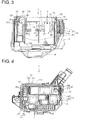
FIG. 3 is a cross-sectional view taken along the line III-III inFIG. 2 ; -
FIG. 4 is a plan view of a body of the junction box unit illustrated inFIG. 1 ; -
FIG. 5 is a perspective view of a connector cover of the junction box unit illustrated inFIG. 1 ; -
FIG. 6 is a perspective view of the connector cover illustrated inFIG. 5 ; -
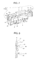
FIG 7 is another perspective view of the connector cover illustrated inFIG. 5 ; -
FIG. 8 is a plan view of the first mounting portion of the connector cover illustrated inFIG 5 ; -
FIG. 9 is a perspective view of the junction box unit illustrated inFIG. 1 ; -
FIG. 10 is a perspective view of the junction box unit illustrated inFIG. 9 in which the connector cover is detached therefrom; -
FIG 11 is a perspective view of illustrated of the connector cover illustrated inFIG. 10 in which the connector of a wiring harness detached from the connector cover is attached to the power integration unit; and -
FIG 12 is a perspective view of the power integration unit illustrated inFIG. 11 that is attached to the body. - The connector cover and junction box unit according to one exemplary embodiment of the present invention is described with reference to
FIGS. 1 to 12 . - With reference to
FIGS. 1 to 3 , there is shown ajunction box unit 1 that comprises anelectrical junction box 2 having abody 3 and aconnector cover 4. - The
electrical junction box 2 is adapted to be mounted in automobile or other vehicles. Theelectrical junction box 2 comprises the body 3 (illustrated inFIG. 4 ), apower integration unit 5 serving as an electric component (illustrated inFIG. 11 ), a not-shown upper cover, and a lower cover 6 (illustrated inFIG. 9 ). - Referring to
FIGS. 2 and4 , thebody 3 has a rectangular shape in plan view. Various electric components such as a relay 7 (illustrated inFIG. 2 ) and a fuse 36 (illustrated inFIG 2 ) are attached to thebody 3 at an upper surface thereof. The upper surface of thebody 3 is illustrated in an upper portion ofFIG. 1 . Also, a connector 9 (as illustrated inFIG 10 ) of an automotive wiring harness 8 (shown partly inFIG 10 ) is connected to thebody 3 at a lower surface thereof. The lower surface is illustrated in a lower portion ofFIG 1 . - The
wiring harness 8 includes a plurality of electrical wires 10 (shown partly inFIG 10 ) and a plurality of the connectors 9 (shown partly inFIG 10 ) each attached to a group of ends of theelectrical wires 10. Some of theconnectors 9 are adapted to be connected to the various electronic components incorporated in the automobile, while the other thereof are connected to the lower surface of thebody 3, and remaining two connectors are connected to a lower surface of thepower integration unit 5. The lower surface of thepower integration unit 5 is illustrated in a lower portion ofFIG. 11 . - Referring to
FIG. 4 , thebody 3 includes acomponent accommodation portion 11. Thecomponent accommodation portion 11 is provided near an edge of thebody 3 such that thecomponent accommodation portion 11 defines a space extending through thebody 3 in a direction in which the upper and lower surfaces are opposed to each other. - The
component accommodation portion 11 has a rectangular shape in plan view. A length direction in a planar dimension of theaccommodation portion 11 is parallel to a length direction in a planar dimension of thebody 3. Thecomponent accommodation portion 11 has twoinner surfaces 11 a opposed to each other in the length direction, and theinner surfaces 11 a each include a locking arm 12 (serving as a locking portion in the context of the scope of protection of the present invention) and a pair ofpositioning grooves 13. - The locking
arm 12 in its literal sense takes a shape of an arm and includes one end continuing to the edge of theinner surface 11a at the lower side and the other end residing at the upper side and provided as a free end. Athroughhole 14 is provided at the centre of the lockingarm 12 over a substantially full length of the lockingarm 12. A later-describedengagement projection 15 of thepower integration unit 5 enters the throughhole 14 such that theengagement projection 15 is caught by the above-described other end, so that theengagement projection 15 of thepower integration unit 5 is brought into locking engagement with the lockingarm 12. By virtue of the locking engagement with theengagement projection 15, the lockingarm 12 secures thepower integration unit 5 to thebody 3 in a state where thepower integration unit 5 is accommodated in thecomponent accommodation portion 11. - The
positioning grooves 13 are provided in a shape of a recess on theinner surface 11a such that the lockingarm 12 is positioned therebetween. Also, a length direction of thepositioning groove 13 is parallel to a length direction of the lockingarm 12. As illustrated inFIG. 4 , the pair ofpositioning grooves 13 each includeparallel portions 27 provided in a shape of a recess on theinner surface 11 a and parallel to each other, and spaced-apartportions 28 continuing to theparallel portions 27 and extending in a direction away from each other. - Also, a terminal fitting attached to an end of the power cable connected to a power source such as a battery and a generator is attached to the
body 3. - A not-shown busbar is provided inside of the
body 3. The busbar is obtained by punching and bending of a conductive metal plate. The busbar is adapted to electrically connect therelay 7 and fuse 36 attached to the upper surface of thebody 3, the terminals of theconnectors 9 of thewiring harness 8 attached to the lower surface thereof, the terminal fitting attached to the end of the power cable, and thepower integration unit 5 to each other in accordance with a predetermined pattern. - As illustrated in
FIG. 11 , thepower integration unit 5 has an external appearance of a flat box sized and dimensioned to be accommodated in thecomponent accommodation portion 11. Thepower integration unit 5 accommodates therein a circuit board incorporating thereupon the relays and fuses. - The
connector 9 of thewiring harness 8 is connected to the lower surface of thepower integration unit 5, the lower surface being illustrated in the lower portion ofFIG. 11 . The terminal of theconnector 9 is connected to the circuit board residing in thepower integration unit 5. - Electrical power from the power source is fed to the circuit board via the busbar disposed within the
body 3. Also, thepower integration unit 5 includesengagement projections 15 on the both ends thereof in its length direction, theengagement projections 15 taking a shape of a projection and sized and dimensioned to be brought into locking engagement with the lockingarm 12; and arib 16 sized and dimensioned to enter thepositioning groove 13. - The
power integration unit 5 is inserted into thecomponent accommodation portion 11 in a state where theconnector 9 of thewiring harness 8 is connected to the lower surface of thepower integration unit 5. In this manner, thepower integration unit 5 is accommodated in thebody 3 with theengagement projection 15 brought into locking engagement with the lockingarm 12. - The upper cover is made of insulating synthetic resin and configured to be attached to the
body 3 such that the top surface of thebody 3 is covered by the upper cover. The lower cover is made of insulating synthetic resin and configured to be attached to thebody 3 such that the lower surface of thebody 3 is covered by the lower cover. - The
electrical junction box 2 having the above-described configuration supplies part of the electricity from the power cable via therelay 7, fuse 36, and the fuses and relays in thepower integration unit 5, and by way of thewiring harness 8, to the electronic components incorporated in the automobile. - The
connector cover 4 is adapted and configured to provide positioning of theconnector 9 of thewiring harness 8 attached to thepower integration unit 5, the positioning being provided relative to thebody 3 to which thepower integration unit 5 is yet to be attached. - The
connector cover 4 is made of insulating synthetic resin and in a shape of a flat box with size and dimensions that allow the connector over 11 to be accommodated in thecomponent accommodation portion 11. - Referring to
FIGS. 5 to 7 , theconnector cover 4 includes a box-shapedmain body 17, a holdingportion 18, and a mountingportion 19. When theconnector cover 4 is attached to thebody 3, themain body 17 is accommodated in thecomponent accommodation portion 11 and thus in thebody 3. - The holding
portion 18 continues to themain body 17 adapted to be accommodated in thecomponent accommodation portion 11 at a lower side of thebody 3. The holdingportion 18 includes a plurality of extendedwalls 20 extending downward from themain body 17 in parallel with each other (four walls shown in the illustrated example); and hookingwalls 21 each continuing to an end of theextended walls 20, the end being a distal end with respect to themain body 17. - The
extended walls 20 each include in one piece therewith anengagement arm 22 adapted to be brought into locking engagement with an outer surface of theconnector 9. The hookingwalls 21 each extend in a direction in which the mutually adjacent pair of theextended walls 20 become close to each other. - The holding
portion 18 having the above-described configuration positions theconnector 9 between the mutually adjacent twoextended walls 20 and between themain body 17 and the hookingwall 21 so that theconnector 9 is held thereby. At this point, theengagement arm 22 and the outer surface of theconnector 9 are placed in locking engagement with each other, so that theconnector 9 is not inadvertently detached from themain body 17. - The mounting
portion 19 includes a first mountingportion 23 and a second mountingportion 24. In a state where themain body 17 of theconnector cover 4 is accommodated in thecomponent accommodation portion 11 of thebody 3, the first mountingportion 23 resides on an outer surface of oneend 17a of themain body 17 in its length direction, the oneend 17a facing the onelocking arm 12. - As illustrated in
FIG. 8 , the first mountingportion 23 includes anengagement projection 25 and a pair of positioningribs 26. - The
engagement projection 25 protrudes from the outer surface of the oneend 17a of themain body 17 in its length direction. Theengagement projection 25 is adapted, in a state where themain body 17 is accommodated in thecomponent accommodation portion 11, enters thethroughhole 14 of the lockingarm 12 to be brought into locking engagement with the lockingarm 12. - The pair of positioning
ribs 26 are provided such that theengagement projection 25 is positioned therebetween, and each have a shape of a protrusion formed on the outer surface of the oneend 17a of themain body 17 in its length direction and in a direction orthogonal to the outer surface. Thepositioning ribs 26 each extend in a straight manner and in parallel with the length direction of the later-describedengagement arm 30 of the second mountingportion 24. When themain body 17 is accommodated in thecomponent accommodation portion 11, thepositioning ribs 26 only enter theparallel portion 27 of thepositioning groove 13 to position the main body 17 (and accordingly the connector cover 4) with respect to the component accommodation portion 11 (and accordingly to the body 3). - Also, a reduced
portion 29 in the context of the scope of protection of the present invention is provided at an end of the pair of positioningribs 26 close to the upper surface of thebody 3 and away from the holdingportion 18. The amount of protrusion of the reducedportion 29 with reference to the outer surface of themain body 17 decreases as the reducedportion 29 becomes close to the end of thepositioning rib 26 on the side of the upper surface and becomes away from the holdingportion 18. - When the
main body 17 is accommodated in thecomponent accommodation portion 11, the second mountingportion 24 will be found on the outer surface of theother end 17b of themain body 17 facing theother locking arm 12 in the length direction. The second mountingportion 24 includes oneengagement arm 30 and a pair of positioningribs 31. - The
engagement arm 30 includes, as illustrated inFIG. 3 , an armmain body 32 and aprotrusion 33. The armmain body 32 has a shape of a strip, whose one end continues to a lower portion of the outer surface of theother end 17b of themain body 17, and the other end being a free end extending from the one end toward the upper surface. Theprotrusion 33 is provided at a central portion of the armmain body 32 in a protruding manner. Theprotrusion 33, when themain body 17 is accommodated in thecomponent accommodation portion 11, enters thethroughhole 14 of the lockingarm 12 to be brought into locking engagement with the lockingarm 12. When theprotrusion 33 is brought into locking engagement with the lockingarm 12, the other end opposite the free end of the armmain body 32 will protrude closer to the upper surface and accordingly the out of thebody 3 than the tip on the side of the upper surface of the lockingarm 12. - The pair of positioning
ribs 31 are provided such that theengagement arm 30 is positioned therebetween, and each extend in a straight manner and in parallel with the length direction of theengagement arm 30. - The
positioning ribs 31 each include in one piece therewith an orthogonal protrudingportion 34 and a parallel protrudingportion 35. The orthogonal protrudingportion 34 protrudes from the outer surface of theother end 17b of themain body 17 in its length direction and extending in a direction orthogonal to the outer surface, and is configured to enter theparallel portion 27. The parallel protrudingportion 35 continues to the tip of the orthogonal protrudingportion 34 and extends in a direction in which the pair of positioningribs 31 becomes away from each other, and in parallel with the outer surface, and is configured to enter the spaced-apartportion 28. When themain body 17 is accommodated in thecomponent accommodation portion 11, thepositioning rib 31 enters thepositioning groove 13 and positions themain body 17, and positions, by virtue of positioning of themain body 17, theconnector cover 4 with respect to thecomponent accommodation portion 11 and thus with respect to thebody 3. - The
connector cover 4 having the above-described configuration is used in the following manner as theelectrical junction box 2 is assembled into a finished product. - First, as illustrated in
FIG. 9 , in a state where theconnector 9 to be attached to thepower integration unit 5 is held by the holdingportion 18, theconnector cover 4 is accommodated in thecomponent accommodation portion 11 to be attached to thebody 3, and in this state conveyed as thejunction box unit 1 to the automotive assembly line. At this point, as illustrated inFIG 3 , theengagement projection 25 is in locking engagement with one of the lockingarms 12, theprotrusion 33 of theengagement arm 30 is in locking engagement with the other of the lockingarms 12, and thus theconnector cover 4 is secured to thebody 3. Here, it is appreciated that thepositioning ribs positioning groove 13. - Also, on the automotive assembly line, the other end of the
engagement arm 30 protruding closer to theprotrusion 33 of the armmain body 32 is moved close to themain body 17, so that the locking engagement with theother locking arm 12 of theengagement arm 30 is exited. Further, theconnector cover 4 is rotated about oneend 17a of themain body 17, taken out of thecomponent accommodation portion 11, and detached from thebody 3 as illustrated inFIG. 10 . Here, it is appreciated that theconnector 9 held by the holdingportion 18 is taken out of thebody 3 in conjunction with theconnector cover 4. Also, theconnector 9 is detached from theconnector cover 4, and theseconnectors 9 are attached to thepower integration unit 5 as illustrated inFIG 11 . - Further, as illustrated in
FIG. 12 , thepower integration unit 5 is accommodated in thecomponent accommodation portion 11 to be attached to thebody 3. After that, the upper cover is attached to theelectrical junction box 2, theelectrical junction box 2 is assembled into the finished product, and then mounted in the automobile. - In this manner, the
electrical junction box 2 that has been assembled and mounted in the automobile distributes the electrical power from the automobile's power source via therelay 7, fuse 36, andpower integration unit 5, to the electronic components of the automobile. - According to this embodiment, the mounting
portion 19 includes theengagement projection 25 protruding from the one end of themain body 17 and theengagement arm 30 provided at the other end of themain body 17, and the other end of theengagement arm 30 is more outwardly positioned than the lockingarm 12 provided on thebody 3. By virtue of this configuration, the other end of theengagement arm 30 can be moved in the direction toward the outer surface of themain body 17 to exit the state of locking engagement with the lockingarm 12, and the state of locking engagement with theengagement arm 30 is readily exited. Thus, theconnector cover 4 can be readily detached from thebody 3. Accordingly, theconnector cover 4 can be readily detached from thebody 3. - Since the one
end 17a of themain body 17 where theengagement projection 25 is provided includes thepositioning ribs 26, positioning of theconnector cover 4 attached to thebody 3 can be realized by thepositioning ribs 26. Also, since thepositioning ribs 26 each include the reducedportion 29 whose degree of protrusion decreases as the reducedportion 29 becomes away from the holdingportion 18, it is made possible to prevent thepositioning ribs 26 from getting caught by thebody 3 as locking engagement of theengagement arm 30 is exited and theconnector cover 4 is detached from the body. Thus, theconnector cover 4 can be reliably detached from thebody 3. - Since the pair of the
positioning ribs 26 are provided and theengagement projection 25 is positioned between the pair of thepositioning ribs 26, positioning of theconnector cover 4 attached to thebody 3 can be reliably achieved. - Also, since the
junction box unit 1 includes theconnector cover 4, the other end of theengagement arm 30 can be readily moved in the direction in which it is taken out of locking engagement with the lockingarm 12, the state of locking engagement with theengagement arm 30 can be readily exited, and theconnector cover 4 can be readily detached from thebody 3. - It should be noted that, in the above-described embodiment, the
connector cover 4 is detached from thebody 3 and thepower integration unit 5 is attached to thebody 3 and thus theelectrical junction box 2 is assembled. However, the present invention may be configured such that theconnector cover 4 remains attached to thebody 3 and thepower integration unit 5 is not attached to thebody 3, and thus theelectrical junction box 2 is assembled. - It should be noted that, in the above-described embodiment, the
connector cover 4 is configured to hold theconnector 9 that is attached to thepower integration unit 5 serving as the electric component. However, the present invention may be configured such that theconnector cover 4 is configured to hold theconnector 9 that is attached to therelay 7 or any other electric component other than thepower integration unit 5. - While the exemplary embodiments of the present invention have been described by way of example, it will be appreciated by those skilled in the art may make various modifications in the light of the above teaching and within the scope and sprit of the present invention, and the scope of the invention is to be defined by the claims appended hereto.
Claims (4)
- A connector cover comprising:a main body sized and dimensioned to be accommodated in a body of an electrical junction box;a holding portion configured to hold a connector of a wiring harness; anda mounting portion configured to be attached to the body of the electrical junction box for mounting of the main body thereto such that positioning of the connector of the wiring harness with respect to the body of the electrical junction box is provided, the mounting portion includingan engagement projection protruding from an outer surface of one end of the main body and configured to be brought into locking engagement with a locking portion provided on the body of the electrical junction box, the locking portion being configured to secure an electric component intended to be accommodated in the body of the electrical junction box, andan engagement arm including an arm main body having one end and an other end, the one end continuing to an outer surface of an other end of the main body and the other end being a free end, and a protrusion provided at a central portion of the arm main body and configured to be brought into locking engagement with the locking portion of the body of the electrical junction box, wherein, in a state where the protrusion is in locking engagement with the locking portion, the other end of the arm main body is positioned more outwardly of the body than the locking portion.
- The connector cover recited in claim 1 further comprising a positioning rib protruding from the outer surface of the one end of the main body, extending lengthwise of the engagement arm, the positioning rib including a reduced portion whose degree of protrusion decreases as the reduced portion becomes more spaced from the holding portion.
- The connector cover recited in claim 2 further comprising a pair of the positioning ribs such that the engagement projection is provided therebetween.
- A junction box unit comprising(a) a body of an electrical junction box to which an electric component is attached; and(b) the connector cover of any one of claims 1 to 3, the connector cover being configured to be attached to the body and provide positioning of a connector of a wiring harness with respect to the body.
Applications Claiming Priority (1)
| Application Number | Priority Date | Filing Date | Title |
|---|---|---|---|
| JP2010155425A JP5608447B2 (en) | 2010-07-08 | 2010-07-08 | Connector cover and junction box unit |
Publications (3)
| Publication Number | Publication Date |
|---|---|
| EP2405729A2 true EP2405729A2 (en) | 2012-01-11 |
| EP2405729A3 EP2405729A3 (en) | 2014-12-10 |
| EP2405729B1 EP2405729B1 (en) | 2015-10-28 |
Family
ID=44653976
Family Applications (1)
| Application Number | Title | Priority Date | Filing Date |
|---|---|---|---|
| EP11173034.7A Not-in-force EP2405729B1 (en) | 2010-07-08 | 2011-07-07 | Connector cover and junction box unit provided with the same |
Country Status (4)
| Country | Link |
|---|---|
| US (1) | US8622755B2 (en) |
| EP (1) | EP2405729B1 (en) |
| JP (1) | JP5608447B2 (en) |
| CN (1) | CN102403683B (en) |
Families Citing this family (12)
| Publication number | Priority date | Publication date | Assignee | Title |
|---|---|---|---|---|
| JP5580058B2 (en) * | 2010-01-08 | 2014-08-27 | 矢崎総業株式会社 | Electric junction box fixing structure |
| JP5757892B2 (en) * | 2012-01-31 | 2015-08-05 | 住友電装株式会社 | Electrical junction box |
| JP5648981B2 (en) * | 2012-06-20 | 2015-01-07 | 住友電装株式会社 | Electrical junction box |
| JP5994609B2 (en) * | 2012-11-30 | 2016-09-21 | 矢崎総業株式会社 | Electrical junction box |
| JP6473470B2 (en) * | 2017-03-09 | 2019-02-20 | 矢崎総業株式会社 | Electrical junction box and wire harness |
| US10673218B2 (en) * | 2017-08-17 | 2020-06-02 | Thomas & Betts International Llc | Molded electrical junction box |
| US11024990B2 (en) | 2018-11-30 | 2021-06-01 | Molex, Llc | Connector assembly for connecting multiple cables to electrical device |
| US10992092B2 (en) | 2018-11-30 | 2021-04-27 | Molex, Llc | Connector that connects to electric wires and to other connectors |
| JP7340400B2 (en) | 2018-11-30 | 2023-09-07 | モレックス エルエルシー | connector |
| JP1646280S (en) | 2019-03-26 | 2019-11-25 | ||
| JP1646281S (en) | 2019-03-26 | 2019-11-25 | ||
| JP1643701S (en) | 2019-03-26 | 2019-10-21 |
Citations (1)
| Publication number | Priority date | Publication date | Assignee | Title |
|---|---|---|---|---|
| JP2010155425A (en) | 2009-01-05 | 2010-07-15 | Dainippon Printing Co Ltd | Sheet for preparing sealed letter |
Family Cites Families (14)
| Publication number | Priority date | Publication date | Assignee | Title |
|---|---|---|---|---|
| JPH06302354A (en) * | 1993-04-19 | 1994-10-28 | Yazaki Corp | Multipolar connector |
| JP3400679B2 (en) * | 1997-07-09 | 2003-04-28 | 矢崎総業株式会社 | Lock arm deformation prevention structure |
| US6696640B1 (en) * | 1999-08-23 | 2004-02-24 | Walker Systems, Inc. | Quad receptacle, dual circuit flush poke-through wiring fitting with internally mountable communication/data jacks |
| DE10084595B4 (en) * | 2000-03-15 | 2008-06-26 | The Furukawa Electric Co., Ltd., | Electrical connection box |
| JP3589154B2 (en) * | 2000-05-19 | 2004-11-17 | 住友電装株式会社 | Connection structure between junction box and connector |
| JP2001339824A (en) | 2000-05-25 | 2001-12-07 | Yazaki Corp | Electrical connection box |
| JP3840039B2 (en) * | 2000-06-01 | 2006-11-01 | 矢崎総業株式会社 | Inertia lock connector |
| JP2003333728A (en) * | 2002-05-10 | 2003-11-21 | Sumitomo Wiring Syst Ltd | Coupling structure between junction box and accessory electric junction box |
| JP2004312793A (en) * | 2003-04-02 | 2004-11-04 | Yazaki Corp | Electric junction box and assembling method thereof |
| JP4084259B2 (en) | 2003-07-28 | 2008-04-30 | 矢崎総業株式会社 | Electrical junction box |
| JP5026859B2 (en) * | 2007-05-28 | 2012-09-19 | 矢崎総業株式会社 | Electrical junction box |
| JP5384846B2 (en) * | 2008-04-03 | 2014-01-08 | 矢崎総業株式会社 | Relief terminal structure |
| JP5255966B2 (en) * | 2008-09-18 | 2013-08-07 | 矢崎総業株式会社 | Electrical junction box |
| JP5182581B2 (en) * | 2008-11-05 | 2013-04-17 | 住友電装株式会社 | Electrical junction box and distribution unit |
-
2010
- 2010-07-08 JP JP2010155425A patent/JP5608447B2/en active Active
-
2011
- 2011-07-07 EP EP11173034.7A patent/EP2405729B1/en not_active Not-in-force
- 2011-07-07 US US13/067,924 patent/US8622755B2/en not_active Expired - Fee Related
- 2011-07-08 CN CN201110190308.3A patent/CN102403683B/en not_active Expired - Fee Related
Patent Citations (1)
| Publication number | Priority date | Publication date | Assignee | Title |
|---|---|---|---|---|
| JP2010155425A (en) | 2009-01-05 | 2010-07-15 | Dainippon Printing Co Ltd | Sheet for preparing sealed letter |
Also Published As
| Publication number | Publication date |
|---|---|
| JP5608447B2 (en) | 2014-10-15 |
| CN102403683B (en) | 2015-02-18 |
| US8622755B2 (en) | 2014-01-07 |
| JP2012019611A (en) | 2012-01-26 |
| US20120006594A1 (en) | 2012-01-12 |
| EP2405729A3 (en) | 2014-12-10 |
| CN102403683A (en) | 2012-04-04 |
| EP2405729B1 (en) | 2015-10-28 |
Similar Documents
| Publication | Publication Date | Title |
|---|---|---|
| EP2405729B1 (en) | Connector cover and junction box unit provided with the same | |
| US8002569B2 (en) | Electric connection box | |
| US8723038B2 (en) | Plate metal member, bus bar, and electrical junction box having the bus bar | |
| JP5130110B2 (en) | Electrical junction box | |
| CN101183772B (en) | Electrical junction box | |
| JP5813387B2 (en) | Electrical junction box | |
| JP6505065B2 (en) | Branch structure and wire harness | |
| US7442099B2 (en) | Metal terminal and electric distribution box provided with the same | |
| JP5150291B2 (en) | Electrical junction box | |
| US9148964B2 (en) | Electrical junction box | |
| US8804314B2 (en) | Electric junction box | |
| EP1670100A1 (en) | Electric connection box | |
| JP5859228B2 (en) | Box | |
| US20070117420A1 (en) | Holder | |
| JP2008123928A (en) | Terminal metal fitting and electrical junction box having the same | |
| CN103563040A (en) | Fusible link mounting structure and electrical junction box | |
| JP2010093955A (en) | Electrical junction box | |
| JP2009171763A (en) | Electrical junction box | |
| JP5156499B2 (en) | Electrical junction box | |
| JP5805983B2 (en) | Sheet metal member, bus bar, and electrical junction box provided with the bus bar | |
| US9796346B2 (en) | Motor vehicle plastic panel having an integral electrical unit | |
| JP7107659B2 (en) | electric junction box | |
| JP2006149165A (en) | Electric connection box | |
| JP2006166621A (en) | Protector and electric connection box equipped with that protector | |
| JP4340222B2 (en) | Electrical junction box |
Legal Events
| Date | Code | Title | Description |
|---|---|---|---|
| AK | Designated contracting states |
Kind code of ref document: A2 Designated state(s): AL AT BE BG CH CY CZ DE DK EE ES FI FR GB GR HR HU IE IS IT LI LT LU LV MC MK MT NL NO PL PT RO RS SE SI SK SM TR |
|
| AX | Request for extension of the european patent |
Extension state: BA ME |
|
| PUAI | Public reference made under article 153(3) epc to a published international application that has entered the european phase |
Free format text: ORIGINAL CODE: 0009012 |
|
| PUAL | Search report despatched |
Free format text: ORIGINAL CODE: 0009013 |
|
| AK | Designated contracting states |
Kind code of ref document: A3 Designated state(s): AL AT BE BG CH CY CZ DE DK EE ES FI FR GB GR HR HU IE IS IT LI LT LU LV MC MK MT NL NO PL PT RO RS SE SI SK SM TR |
|
| AX | Request for extension of the european patent |
Extension state: BA ME |
|
| RIC1 | Information provided on ipc code assigned before grant |
Ipc: H01R 13/518 20060101ALI20141105BHEP Ipc: H05K 7/02 20060101AFI20141105BHEP Ipc: H05K 7/14 20060101ALI20141105BHEP Ipc: H01R 13/506 20060101ALI20141105BHEP |
|
| 17P | Request for examination filed |
Effective date: 20150429 |
|
| RBV | Designated contracting states (corrected) |
Designated state(s): AL AT BE BG CH CY CZ DE DK EE ES FI FR GB GR HR HU IE IS IT LI LT LU LV MC MK MT NL NO PL PT RO RS SE SI SK SM TR |
|
| GRAP | Despatch of communication of intention to grant a patent |
Free format text: ORIGINAL CODE: EPIDOSNIGR1 |
|
| RIC1 | Information provided on ipc code assigned before grant |
Ipc: H05K 7/14 20060101ALI20150529BHEP Ipc: H01R 13/506 20060101ALI20150529BHEP Ipc: H01R 13/518 20060101ALI20150529BHEP Ipc: H05K 7/02 20060101AFI20150529BHEP |
|
| INTG | Intention to grant announced |
Effective date: 20150625 |
|
| GRAS | Grant fee paid |
Free format text: ORIGINAL CODE: EPIDOSNIGR3 |
|
| GRAA | (expected) grant |
Free format text: ORIGINAL CODE: 0009210 |
|
| AK | Designated contracting states |
Kind code of ref document: B1 Designated state(s): AL AT BE BG CH CY CZ DE DK EE ES FI FR GB GR HR HU IE IS IT LI LT LU LV MC MK MT NL NO PL PT RO RS SE SI SK SM TR |
|
| REG | Reference to a national code |
Ref country code: GB Ref legal event code: FG4D |
|
| REG | Reference to a national code |
Ref country code: CH Ref legal event code: EP |
|
| REG | Reference to a national code |
Ref country code: AT Ref legal event code: REF Ref document number: 758524 Country of ref document: AT Kind code of ref document: T Effective date: 20151115 |
|
| REG | Reference to a national code |
Ref country code: IE Ref legal event code: FG4D |
|
| REG | Reference to a national code |
Ref country code: DE Ref legal event code: R096 Ref document number: 602011020950 Country of ref document: DE |
|
| REG | Reference to a national code |
Ref country code: LT Ref legal event code: MG4D |
|
| REG | Reference to a national code |
Ref country code: NL Ref legal event code: MP Effective date: 20151028 |
|
| REG | Reference to a national code |
Ref country code: AT Ref legal event code: MK05 Ref document number: 758524 Country of ref document: AT Kind code of ref document: T Effective date: 20151028 |
|
| PG25 | Lapsed in a contracting state [announced via postgrant information from national office to epo] |
Ref country code: NL Free format text: LAPSE BECAUSE OF FAILURE TO SUBMIT A TRANSLATION OF THE DESCRIPTION OR TO PAY THE FEE WITHIN THE PRESCRIBED TIME-LIMIT Effective date: 20151028 Ref country code: LT Free format text: LAPSE BECAUSE OF FAILURE TO SUBMIT A TRANSLATION OF THE DESCRIPTION OR TO PAY THE FEE WITHIN THE PRESCRIBED TIME-LIMIT Effective date: 20151028 Ref country code: IS Free format text: LAPSE BECAUSE OF FAILURE TO SUBMIT A TRANSLATION OF THE DESCRIPTION OR TO PAY THE FEE WITHIN THE PRESCRIBED TIME-LIMIT Effective date: 20160228 Ref country code: HR Free format text: LAPSE BECAUSE OF FAILURE TO SUBMIT A TRANSLATION OF THE DESCRIPTION OR TO PAY THE FEE WITHIN THE PRESCRIBED TIME-LIMIT Effective date: 20151028 Ref country code: IT Free format text: LAPSE BECAUSE OF FAILURE TO SUBMIT A TRANSLATION OF THE DESCRIPTION OR TO PAY THE FEE WITHIN THE PRESCRIBED TIME-LIMIT Effective date: 20151028 Ref country code: NO Free format text: LAPSE BECAUSE OF FAILURE TO SUBMIT A TRANSLATION OF THE DESCRIPTION OR TO PAY THE FEE WITHIN THE PRESCRIBED TIME-LIMIT Effective date: 20160128 Ref country code: ES Free format text: LAPSE BECAUSE OF FAILURE TO SUBMIT A TRANSLATION OF THE DESCRIPTION OR TO PAY THE FEE WITHIN THE PRESCRIBED TIME-LIMIT Effective date: 20151028 |
|
| PG25 | Lapsed in a contracting state [announced via postgrant information from national office to epo] |
Ref country code: SE Free format text: LAPSE BECAUSE OF FAILURE TO SUBMIT A TRANSLATION OF THE DESCRIPTION OR TO PAY THE FEE WITHIN THE PRESCRIBED TIME-LIMIT Effective date: 20151028 Ref country code: AT Free format text: LAPSE BECAUSE OF FAILURE TO SUBMIT A TRANSLATION OF THE DESCRIPTION OR TO PAY THE FEE WITHIN THE PRESCRIBED TIME-LIMIT Effective date: 20151028 Ref country code: RS Free format text: LAPSE BECAUSE OF FAILURE TO SUBMIT A TRANSLATION OF THE DESCRIPTION OR TO PAY THE FEE WITHIN THE PRESCRIBED TIME-LIMIT Effective date: 20151028 Ref country code: LV Free format text: LAPSE BECAUSE OF FAILURE TO SUBMIT A TRANSLATION OF THE DESCRIPTION OR TO PAY THE FEE WITHIN THE PRESCRIBED TIME-LIMIT Effective date: 20151028 Ref country code: FI Free format text: LAPSE BECAUSE OF FAILURE TO SUBMIT A TRANSLATION OF THE DESCRIPTION OR TO PAY THE FEE WITHIN THE PRESCRIBED TIME-LIMIT Effective date: 20151028 Ref country code: GR Free format text: LAPSE BECAUSE OF FAILURE TO SUBMIT A TRANSLATION OF THE DESCRIPTION OR TO PAY THE FEE WITHIN THE PRESCRIBED TIME-LIMIT Effective date: 20160129 Ref country code: PT Free format text: LAPSE BECAUSE OF FAILURE TO SUBMIT A TRANSLATION OF THE DESCRIPTION OR TO PAY THE FEE WITHIN THE PRESCRIBED TIME-LIMIT Effective date: 20160229 Ref country code: PL Free format text: LAPSE BECAUSE OF FAILURE TO SUBMIT A TRANSLATION OF THE DESCRIPTION OR TO PAY THE FEE WITHIN THE PRESCRIBED TIME-LIMIT Effective date: 20151028 |
|
| REG | Reference to a national code |
Ref country code: FR Ref legal event code: PLFP Year of fee payment: 6 |
|
| PG25 | Lapsed in a contracting state [announced via postgrant information from national office to epo] |
Ref country code: CZ Free format text: LAPSE BECAUSE OF FAILURE TO SUBMIT A TRANSLATION OF THE DESCRIPTION OR TO PAY THE FEE WITHIN THE PRESCRIBED TIME-LIMIT Effective date: 20151028 |
|
| REG | Reference to a national code |
Ref country code: DE Ref legal event code: R097 Ref document number: 602011020950 Country of ref document: DE |
|
| PG25 | Lapsed in a contracting state [announced via postgrant information from national office to epo] |
Ref country code: DK Free format text: LAPSE BECAUSE OF FAILURE TO SUBMIT A TRANSLATION OF THE DESCRIPTION OR TO PAY THE FEE WITHIN THE PRESCRIBED TIME-LIMIT Effective date: 20151028 Ref country code: RO Free format text: LAPSE BECAUSE OF FAILURE TO SUBMIT A TRANSLATION OF THE DESCRIPTION OR TO PAY THE FEE WITHIN THE PRESCRIBED TIME-LIMIT Effective date: 20151028 Ref country code: EE Free format text: LAPSE BECAUSE OF FAILURE TO SUBMIT A TRANSLATION OF THE DESCRIPTION OR TO PAY THE FEE WITHIN THE PRESCRIBED TIME-LIMIT Effective date: 20151028 Ref country code: SK Free format text: LAPSE BECAUSE OF FAILURE TO SUBMIT A TRANSLATION OF THE DESCRIPTION OR TO PAY THE FEE WITHIN THE PRESCRIBED TIME-LIMIT Effective date: 20151028 Ref country code: SM Free format text: LAPSE BECAUSE OF FAILURE TO SUBMIT A TRANSLATION OF THE DESCRIPTION OR TO PAY THE FEE WITHIN THE PRESCRIBED TIME-LIMIT Effective date: 20151028 |
|
| PLBE | No opposition filed within time limit |
Free format text: ORIGINAL CODE: 0009261 |
|
| STAA | Information on the status of an ep patent application or granted ep patent |
Free format text: STATUS: NO OPPOSITION FILED WITHIN TIME LIMIT |
|
| 26N | No opposition filed |
Effective date: 20160729 |
|
| PG25 | Lapsed in a contracting state [announced via postgrant information from national office to epo] |
Ref country code: SI Free format text: LAPSE BECAUSE OF FAILURE TO SUBMIT A TRANSLATION OF THE DESCRIPTION OR TO PAY THE FEE WITHIN THE PRESCRIBED TIME-LIMIT Effective date: 20151028 |
|
| PG25 | Lapsed in a contracting state [announced via postgrant information from national office to epo] |
Ref country code: BE Free format text: LAPSE BECAUSE OF FAILURE TO SUBMIT A TRANSLATION OF THE DESCRIPTION OR TO PAY THE FEE WITHIN THE PRESCRIBED TIME-LIMIT Effective date: 20151028 |
|
| REG | Reference to a national code |
Ref country code: CH Ref legal event code: PL |
|
| PG25 | Lapsed in a contracting state [announced via postgrant information from national office to epo] |
Ref country code: MC Free format text: LAPSE BECAUSE OF FAILURE TO SUBMIT A TRANSLATION OF THE DESCRIPTION OR TO PAY THE FEE WITHIN THE PRESCRIBED TIME-LIMIT Effective date: 20151028 |
|
| PG25 | Lapsed in a contracting state [announced via postgrant information from national office to epo] |
Ref country code: LI Free format text: LAPSE BECAUSE OF NON-PAYMENT OF DUE FEES Effective date: 20160731 Ref country code: CH Free format text: LAPSE BECAUSE OF NON-PAYMENT OF DUE FEES Effective date: 20160731 |
|
| REG | Reference to a national code |
Ref country code: IE Ref legal event code: MM4A |
|
| REG | Reference to a national code |
Ref country code: FR Ref legal event code: PLFP Year of fee payment: 7 |
|
| PG25 | Lapsed in a contracting state [announced via postgrant information from national office to epo] |
Ref country code: IE Free format text: LAPSE BECAUSE OF NON-PAYMENT OF DUE FEES Effective date: 20160707 |
|
| PG25 | Lapsed in a contracting state [announced via postgrant information from national office to epo] |
Ref country code: LU Free format text: LAPSE BECAUSE OF NON-PAYMENT OF DUE FEES Effective date: 20160707 |
|
| PG25 | Lapsed in a contracting state [announced via postgrant information from national office to epo] |
Ref country code: HU Free format text: LAPSE BECAUSE OF FAILURE TO SUBMIT A TRANSLATION OF THE DESCRIPTION OR TO PAY THE FEE WITHIN THE PRESCRIBED TIME-LIMIT; INVALID AB INITIO Effective date: 20110707 Ref country code: CY Free format text: LAPSE BECAUSE OF FAILURE TO SUBMIT A TRANSLATION OF THE DESCRIPTION OR TO PAY THE FEE WITHIN THE PRESCRIBED TIME-LIMIT Effective date: 20151028 |
|
| REG | Reference to a national code |
Ref country code: FR Ref legal event code: PLFP Year of fee payment: 8 |
|
| PG25 | Lapsed in a contracting state [announced via postgrant information from national office to epo] |
Ref country code: MK Free format text: LAPSE BECAUSE OF FAILURE TO SUBMIT A TRANSLATION OF THE DESCRIPTION OR TO PAY THE FEE WITHIN THE PRESCRIBED TIME-LIMIT Effective date: 20151028 Ref country code: TR Free format text: LAPSE BECAUSE OF FAILURE TO SUBMIT A TRANSLATION OF THE DESCRIPTION OR TO PAY THE FEE WITHIN THE PRESCRIBED TIME-LIMIT Effective date: 20151028 Ref country code: MT Free format text: LAPSE BECAUSE OF NON-PAYMENT OF DUE FEES Effective date: 20160731 |
|
| PG25 | Lapsed in a contracting state [announced via postgrant information from national office to epo] |
Ref country code: BG Free format text: LAPSE BECAUSE OF FAILURE TO SUBMIT A TRANSLATION OF THE DESCRIPTION OR TO PAY THE FEE WITHIN THE PRESCRIBED TIME-LIMIT Effective date: 20151028 |
|
| PG25 | Lapsed in a contracting state [announced via postgrant information from national office to epo] |
Ref country code: AL Free format text: LAPSE BECAUSE OF FAILURE TO SUBMIT A TRANSLATION OF THE DESCRIPTION OR TO PAY THE FEE WITHIN THE PRESCRIBED TIME-LIMIT Effective date: 20151028 |
|
| PGFP | Annual fee paid to national office [announced via postgrant information from national office to epo] |
Ref country code: FR Payment date: 20190619 Year of fee payment: 9 |
|
| PGFP | Annual fee paid to national office [announced via postgrant information from national office to epo] |
Ref country code: DE Payment date: 20190625 Year of fee payment: 9 |
|
| PGFP | Annual fee paid to national office [announced via postgrant information from national office to epo] |
Ref country code: GB Payment date: 20190703 Year of fee payment: 9 |
|
| REG | Reference to a national code |
Ref country code: DE Ref legal event code: R119 Ref document number: 602011020950 Country of ref document: DE |
|
| GBPC | Gb: european patent ceased through non-payment of renewal fee |
Effective date: 20200707 |
|
| PG25 | Lapsed in a contracting state [announced via postgrant information from national office to epo] |
Ref country code: GB Free format text: LAPSE BECAUSE OF NON-PAYMENT OF DUE FEES Effective date: 20200707 Ref country code: FR Free format text: LAPSE BECAUSE OF NON-PAYMENT OF DUE FEES Effective date: 20200731 |
|
| PG25 | Lapsed in a contracting state [announced via postgrant information from national office to epo] |
Ref country code: DE Free format text: LAPSE BECAUSE OF NON-PAYMENT OF DUE FEES Effective date: 20210202 |