EP2405664A2 - Stereoscopic Glasses and Display Apparatus Including the Same - Google Patents
Stereoscopic Glasses and Display Apparatus Including the Same Download PDFInfo
- Publication number
- EP2405664A2 EP2405664A2 EP11156297A EP11156297A EP2405664A2 EP 2405664 A2 EP2405664 A2 EP 2405664A2 EP 11156297 A EP11156297 A EP 11156297A EP 11156297 A EP11156297 A EP 11156297A EP 2405664 A2 EP2405664 A2 EP 2405664A2
- Authority
- EP
- European Patent Office
- Prior art keywords
- user
- display apparatus
- viewing
- area
- display unit
- Prior art date
- Legal status (The legal status is an assumption and is not a legal conclusion. Google has not performed a legal analysis and makes no representation as to the accuracy of the status listed.)
- Withdrawn
Links
Images


Classifications
-
- H—ELECTRICITY
- H04—ELECTRIC COMMUNICATION TECHNIQUE
- H04N—PICTORIAL COMMUNICATION, e.g. TELEVISION
- H04N13/00—Stereoscopic video systems; Multi-view video systems; Details thereof
- H04N13/10—Processing, recording or transmission of stereoscopic or multi-view image signals
- H04N13/106—Processing image signals
- H04N13/128—Adjusting depth or disparity
-
- H—ELECTRICITY
- H04—ELECTRIC COMMUNICATION TECHNIQUE
- H04N—PICTORIAL COMMUNICATION, e.g. TELEVISION
- H04N13/00—Stereoscopic video systems; Multi-view video systems; Details thereof
- H04N13/10—Processing, recording or transmission of stereoscopic or multi-view image signals
- H04N13/106—Processing image signals
- H04N13/144—Processing image signals for flicker reduction
-
- H—ELECTRICITY
- H04—ELECTRIC COMMUNICATION TECHNIQUE
- H04N—PICTORIAL COMMUNICATION, e.g. TELEVISION
- H04N13/00—Stereoscopic video systems; Multi-view video systems; Details thereof
- H04N13/30—Image reproducers
- H04N13/332—Displays for viewing with the aid of special glasses or head-mounted displays [HMD]
- H04N13/337—Displays for viewing with the aid of special glasses or head-mounted displays [HMD] using polarisation multiplexing
-
- H—ELECTRICITY
- H04—ELECTRIC COMMUNICATION TECHNIQUE
- H04N—PICTORIAL COMMUNICATION, e.g. TELEVISION
- H04N13/00—Stereoscopic video systems; Multi-view video systems; Details thereof
- H04N13/30—Image reproducers
- H04N13/332—Displays for viewing with the aid of special glasses or head-mounted displays [HMD]
- H04N13/341—Displays for viewing with the aid of special glasses or head-mounted displays [HMD] using temporal multiplexing
-
- H—ELECTRICITY
- H04—ELECTRIC COMMUNICATION TECHNIQUE
- H04N—PICTORIAL COMMUNICATION, e.g. TELEVISION
- H04N13/00—Stereoscopic video systems; Multi-view video systems; Details thereof
- H04N13/30—Image reproducers
- H04N13/366—Image reproducers using viewer tracking
- H04N13/383—Image reproducers using viewer tracking for tracking with gaze detection, i.e. detecting the lines of sight of the viewer's eyes
-
- H—ELECTRICITY
- H04—ELECTRIC COMMUNICATION TECHNIQUE
- H04N—PICTORIAL COMMUNICATION, e.g. TELEVISION
- H04N13/00—Stereoscopic video systems; Multi-view video systems; Details thereof
- H04N13/30—Image reproducers
- H04N13/398—Synchronisation thereof; Control thereof
Definitions
- the present invention relates to stereoscopic glasses and a display apparatus including the same, and more particularly to stereoscopic glasses and a display apparatus including the same in which a depth effect of a three-dimensional (3D) image is adjustable to reduce eyestrain of a user.
- 3D three-dimensional
- a display apparatus that can display a 3D image represents depth information with regard to a wide scope provided by a depth map on a 3D display screen.
- the depth information is represented with regard to all of the plurality of objects such that a user's eyes are distributed to all of the plurality of objects. Accordingly, the user may experience vertigo when 3D images of both eyes are combined in a brain, may feel eyestrain, etc., thereby increasing inconvenience.
- a display apparatus including: a signal processor which processes a 3D video signal to have a predetermined depth effect; a display unit which displays the 3D image based on the processed video signal by the signal processor; and a controller which controls the signal processor to process a first area viewed by a user and a second area other than the first area to be different in a level of a depth effect within the 3D image displayed by the display unit.
- the controller may control the signal processor to process the first area to have a depth effect having a predetermined level higher than that of the second area.
- the controller may control the signal processor to process the second area to have a depth effect having a predetermined level lower than that of the first area.
- the display apparatus may further include a sensor which senses the first area viewed by the user within the 3D image displayed by the display unit.
- the sensor may sense a position viewed by the user within the 3D image displayed by the display unit by tracing at least one of a position and a motion of an eyeball of the user, and may generate information about the sensed viewing position.
- the sensor may determine the user's viewing direction with respect to a preset point on the display unit by sensing a position of the user's eyeball, and may generate information about a viewing position by determining the position viewed by the user within the 3D image displayed by the display unit on the basis of the determined viewing direction.
- the display apparatus may further include a coordinate calculator which calculates coordinates corresponding to the viewing position on the display unit on the basis of information about the viewing position.
- the display apparatus may further include a viewing area scope determiner which determines a scope of the user's viewing area within the 3D image displayed by the display unit on the basis of the calculated coordinates.
- the viewing area scope determiner may determine a predetermined scope, where the user's viewing frequency is highest among viewing positions sensed for a predetermined period of time, as the scope of the user's viewing area.
- the viewing area scope determiner may determine an object, where the user's viewing frequency is highest in at least one object included in the image, as the scope of the user's viewing area.
- the 3D image displayed on the display unit may include a plurality of divisional areas, and the viewing area scope determiner may determine at least one area, where a viewing frequency is highest among the plurality of areas, as the scope of the user's viewing area.
- the display apparatus may further include a receiver which receives a video signal, wherein the signal processor includes a depth information extractor which extracts depth information from the 3D video signal when receiving the 3D video signal including the depth information through the receiver, and the controller controls the signal processor to process the second area to have a depth effect having a level lower than that of the extracted depth information.
- the signal processor includes a depth information extractor which extracts depth information from the 3D video signal when receiving the 3D video signal including the depth information through the receiver, and the controller controls the signal processor to process the second area to have a depth effect having a level lower than that of the extracted depth information.
- the display apparatus may further include a receiver which receives a video signal; and a storage unit which stores depth information for reconstructing a two-dimensional (2D) video signal received though the receiver into the 3D video signal, wherein the signal processor processes the received 2D video signal to be reconstructed as the 3D video signal on the basis of the depth information stored in the storage unit, and the controller controls the signal processor to process the second area to have a depth effect having a level lower than that of the stored depth information.
- a receiver which receives a video signal
- a storage unit which stores depth information for reconstructing a two-dimensional (2D) video signal received though the receiver into the 3D video signal
- the signal processor processes the received 2D video signal to be reconstructed as the 3D video signal on the basis of the depth information stored in the storage unit, and the controller controls the signal processor to process the second area to have a depth effect having a level lower than that of the stored depth information.
- the display apparatus may further include stereoscopic glasses including: a frame; a lens unit which is supported by the frame and transmits light corresponding to the 3D image displayed by the display unit to give a predetermined depth effect; and a sensor which senses the user's viewing area within the 3D image displayed by the display unit.
- stereoscopic glasses including: a frame; a lens unit which is supported by the frame and transmits light corresponding to the 3D image displayed by the display unit to give a predetermined depth effect; and a sensor which senses the user's viewing area within the 3D image displayed by the display unit.
- the sensor of the stereoscopic glasses may sense a position viewed by the user within the 3D image displayed by the display unit by tracing at least one of a position and a motion of the user's eyeball, may generate information about the sensed viewing position, and may transmit the information to the display apparatus.
- the sensor of the stereoscopic glasses may determine the user's viewing direction with respect to a preset point on the display unit by sensing a position of the user's eyeball, may generate information about a viewing position by determining the position viewed by the user within the 3D image displayed by the display unit on the basis of the determined viewing direction, and may transmit the information to the display apparatus.
- stereoscopic glasses for viewing a 3D image displayed by a display apparatus, the stereoscopic glasses including: a frame; a lens unit which is supported by the frame and transmits light corresponding to the 3D image displayed by the display apparatus to give a predetermined depth effect; and a sensor which senses a user's viewing area within the 3D image displayed by the display apparatus.
- the sensor may sense a position viewed by the user within the 3D image displayed by the display apparatus by tracing at least one of a position and a motion of the user's eyeball, may generate information about the sensed viewing position, and may transmit the information to the display apparatus.
- the sensor may determine the user's viewing direction with respect to a preset point on the display apparatus by sensing a position of the user's eyeball, may generate information about a viewing position by determining the position viewed by the user within the 3D image displayed by the display apparatus on the basis of the determined viewing direction, and may transmit the information to the display apparatus.
- a method of processing a three-dimensional (3D) video signal including: displaying, by a display unit, a 3D image based on the 3D video signal; and processing a first area determined to be viewed by a user and a second area that is not determined to be viewed by the user, of the 3D image displayed by the display unit, such that the first area is different in level of a depth effect than the second area.
- FIG. 1 is a schematic view of a display system according to an exemplary embodiment.
- the display system includes a display apparatus 100 capable of processing a video signal input from an exterior and displaying an image, and stereoscopic glasses 200 allowing a predetermined cubic effect or depth effect to be recognized corresponding to a three-dimensional (3D) video signal if an image displayed on the display apparatus 100 is a 3D image.
- a display apparatus 100 capable of processing a video signal input from an exterior and displaying an image
- stereoscopic glasses 200 allowing a predetermined cubic effect or depth effect to be recognized corresponding to a three-dimensional (3D) video signal if an image displayed on the display apparatus 100 is a 3D image.
- the display apparatus 100 can process an area viewed by a user within the 3D image displayed on the display unit to have a depth effect different in level from areas other than the viewed area, so that a user's eyestrain can be remarkably reduced when the user views a 3D image, thereby increasing convenience.
- a sensor for sensing a viewing area of a user may be included in at least one of the display apparatus 100 or stereoscopic glasses 200.
- the display apparatus 100 and the stereoscopic glasses 200 may employ polarization glasses or shutter glasses to achieve a stereoscopic effect.
- the display apparatus 100 may include a polarized filter and the polarization glasses are polarized in the same way as the polarized filter so that only an left image can be viewed by a left eye and only a right image can be viewed by a right eye, thereby achieving the stereoscopic effect.
- the display apparatus alternately displays left and right images so that a left glass can be open to a left image and a right glass can be open to a right image, thereby separating the left and right images and achieving the stereoscopic effect.
- the display apparatus 100 may receive a video signal from an external video source (not shown), though it is understood that another exemplary embodiment is not limited in video source thereto.
- the display apparatus 100 may receive a video signal from various video sources such as a computer (not shown) that generates and locally provides a video signal through a central processing unit (not shown) and a graphic card (not shown), a server (not shown) that can provide a video signal through a network, a transmitter of a broadcasting station that can transmit a broadcasting signal through airwaves or a cable, etc.
- the display apparatus 100 receives a two-dimensional (2D) video signal or a 3D video signal from an exterior, and processes the received signal to be displayed as a 2D image or a 3D image.
- the 2D video signal may be reconstructed as a 3D video signal on the basis of predetermined depth information, thereby displaying a 3D image.
- the display apparatus 100 separates the 3D image into left and right images and displays the images in a vertical line.
- the 3D image is seen through the polarization glasses polarized in the same way as the polarized filter, only the left image is input to the left eye and only the right image is input to the right eye, thereby providing a stereoscopic effect.
- the 3D image is divided into a left eye image corresponding to a user's left eye and a right eye image corresponding to a user's right eye.
- the display apparatus 100 receives the 3D video signal, the left eye image and the right eye image are alternately displayed per frame on the basis of the 3D video signal.
- the display apparatus 100 transmits a sync signal to the shutter glasses in order to alternately open and close a left shutter unit and a right shutter unit of the shutter glasses in accordance with the frames for displaying the left eye image or the right eye image.
- the shutter glasses While the display apparatus 100 is displaying the 3D image, the shutter glasses selectively open or close a view of a user's left eye or right eye in accordance with which one of the left eye image or the right eye image is currently displayed. That is, when the display apparatus 100 displays the left eye image, the shutter glasses open the view of the left eye but close the view of the right eye. On the other hand, when the display apparatus 100 displays the right eye image, the shutter glasses open the view of the right eye but close the view of the left eye.
- FIG. 2 is a control block diagram of a display apparatus 100 according to an exemplary embodiment.
- the display apparatus 100 includes a receiver 10, a signal processor 20, a display unit 30, a sensor 40, a coordinate calculator 50, a viewing area scope determiner 60, a storage unit 70, and a controller 80.
- the receiver 10 receives a video signal from an exterior and transmits the received video signal to the signal processor 20, which can be achieved in various manners corresponding to a format of the received video signal and a type of the display apparatus 100.
- the video signal may include at least one of a 2D video signal a 3D video signal, an audio signal, and a data signal.
- the receiver 10 may wirelessly receive a radio frequency (RF) signal transmitted from a broadcast receiving apparatus, or may receive a video signal based on composite video, component video, super video, Syndicat des Constructeurs des Appareils Radiorecepteures et Televiseurs (SCART), high definition multimedia interface (HDMI), etc.
- the receiver 110 may further include an antenna (not shown) and/or a tuner (not shown) for selecting a broadcasting channel.
- the receiver 10 may be realized by: D-SUB capable of transmitting RGB signals based on video graphics array (VGA); a digital video interactive-analog (DVI-A), a DVI-integrated digital/analog (DVI-I) and a DVI-digital (DVI-D) based on DVI; HDMI; etc.
- the receiver 10 may be realized by a DisplayPort, a unified display interface (UDI), a wireless HD interface, etc.
- the signal processor 20 processes a predetermined 3D video signal to have a predetermined depth effect and transmits the processed 3D video signal to the display unit.
- the signal processor 20 can reconstruct the 2D video signal into a 3D video signal on the basis of predetermined depth information (e.g., stored in the storage unit 70), and can transmit the 3D video signal to the display unit 30.
- predetermined depth information e.g., stored in the storage unit 70
- the signal processor 20 may further include a depth information extractor 21 to extract depth information when receiving a 3D video signal including the depth information through the receiver 10.
- a depth information extractor 21 to extract depth information when receiving a 3D video signal including the depth information through the receiver 10.
- the 3D video signal is processed to have the depth effect based on the depth information extracted by the depth information extractor 21, and is then transmitted to the display unit 30.
- the signal processor 20 may perform various image processes with respect to the video signal.
- the image processes may include at least one of decoding and encoding, de-interlacing, frame refresh rate conversion, scaling, noise reduction, detail enhancement, line scanning, etc.
- the signal processor 20 processes the video signal into a plurality of horizontal scan lines per frame and scans the processed video signal to the display unit 30. For example, the signal processor 20 scans an image from a top to a bottom of a display area of the display unit 30. When one frame is completely scanned, an image of the next frame is scanned leaving a preset non-scan period between the frames.
- the signal processor 20 alternately and horizontally scans the video signals, respectively corresponding to the left eye image and the right eye image in the plurality of horizontal scan lines, to the display unit 30 when receiving the video signal corresponding to the stereoscopic image from the receiver 10.
- the signal processor 20 sequentially and alternately scans the video signals, respectively corresponding to the left eye image and the right eye image within the video signal corresponding to the stereoscopic image transmitted through the receiver 10, to the display unit 30.
- the display apparatus 100 may further include a communication unit (not shown) to communicate with the shutter glasses and a signal generator (not shown) to generate sync signals for the left eye image and the right eye image.
- a communication unit not shown
- a signal generator not shown
- the sync signal generated by the signal generator is transmitted to the shutter glasses through the communication unit (not shown), and the shutter glasses alternately opens and closes lens units thereof.
- the signal processor 20 may process an audio signal received through the receiver 10.
- Various audio processes with regard to the audio signal may be performed.
- the audio processes may include at least one of digital conversion of an analog voice signal, amplification of an audio signal, output level control of an audio signal, frequency compensation of an audio signal, etc.
- the display unit 30 displays an image corresponding to a 3D video signal processed by the signal processor 20.
- the plurality of horizontal scan lines are scanned from the signal processor 20 and vertically arranged to thereby display one image frame.
- the display unit 30 includes a display panel (not shown) for displaying the image.
- the display panel (not shown) may include a liquid crystal display (LCD) panel having a liquid crystal layer, an organic light emitting display (OLED) panel having an organic light emitting layer, a plasma display panel (PDP), etc.
- LCD liquid crystal display
- OLED organic light emitting display
- PDP plasma display panel
- the sensor 40 traces a position and/or motion of an eyeball, and senses a position viewed by a user within a 3D image displayed on the display unit 30, thereby generating information about the sensed viewing position.
- the senor 40 may include at least one of an eye tracing sensor and an eye tracing camera for tracing at least one of a position and a motion of a pupil of the eyeball.
- the sensor 40 senses the position of a user's pupil and determines the user's viewing direction with respect to a preset point on the display unit 30.
- an angle between the preset point on the display unit 30 and the sensed position of the pupil is determined, and thus a user's viewing direction on an image displayed in the display unit 30 is determined on the basis of the determined angle.
- the determined viewing direction the position viewed by a user within the 3D image displayed by the display unit 30 is determined, thereby generating information about the viewing position.
- the sensor 40 may trace at least one of the position and the motion of the user's pupil at every vertical sync period of a video signal.
- the coordinate calculator 50 can calculate coordinates corresponding to the viewing position on the display unit on the basis of the information about the viewing position generated by the sensor 40. Corresponding to the viewing position, it is possible to calculate the coordinates of an image pixel displayed on the display unit 30.
- the viewing area scope determiner 60 can determine a scope of the user's viewing area within the 3D image displayed by the display unit 30 based on the coordinates calculated by the coordinate calculator 50.
- the viewing area scope determiner 60 may determine, as the user's viewing area scope, a predetermined scope of at least one position where a user's viewing frequency is highest among the viewing positions sensed for a predetermined time.
- the coordinate calculator 50 calculates a plurality of coordinates. Further, a scope where coordinates having values approximating to a predetermined range are most distributed may be determined among the plurality of coordinates. Thus, a predetermined scope within an image on the display unit 30, corresponding to a scope where the plurality of coordinates having values approximating to the predetermined range are most distributed, may be determined as the user's viewing area scope.
- the viewing area scope determiner 60 may determine a certain object, to which the scope where the coordinates having values approximating to the predetermine range are most distributed belongs, as the user's viewing area scope.
- an object corresponding to the scope where the coordinates having the values approximating to a predetermined range are most distributed for a preset time is selected among the objects, and the selected object is determined as the user's viewing area scope.
- an image includes an object having a human shape and the scope where the coordinates having values approximating to a predetermined range are most distributed for a preset period of time is a head of the human shape
- the whole object having the human shape may be determined as the user's viewing area scope.
- the viewing area scope determiner 60 may determine at least one area among the plurality of areas, which corresponds to a scope where the coordinates having the values approximating to the predetermined range are most distributed, as the user's viewing area scope.
- At least one area corresponding to the scope where the coordinates having the values approximating to the predetermined range may be determined as the user's viewing area scope among the plurality of areas.
- the storage unit 70 may store depth information used to reconstruct a 2D video signal into a 3D video signal when receiving the 2D video signal through the receiver 10.
- the controller 80 may control the signal processor 20 to process an area, being viewed by the user among 3D images displayed by the display unit 30, to have a depth effect different in level from those of other areas not being viewed by the user.
- the controller 80 may control the signal processor 20 to process the determined viewing area scope to have a depth effect different in level from those of areas other than the determined viewing area scope.
- the controller 80 may control the signal processor 20 to process the determined viewing area scope to have a depth effect having a level higher than those of other areas except the determined viewing area scope.
- controller 80 may control the signal processor 20 to process areas except the determined viewing area scope to have a depth effect having a level lower than that of the determined viewing area scope.
- the depth information extractor 21 extracts the depth information from the 3D video signal.
- the controller 80 may control the signal processor 20 so that a viewing area scope determined as being viewed by the user can be processed to have a depth effect corresponding to the extracted depth information but the other areas except the viewing area scope can be processed to have a depth effect having a predetermined level lower than that corresponding to the depth information.
- a 2D video signal may be received through the receiver 10 and reconstructed by the signal processor 20 into a 3D video signal on the basis of depth information (e.g., stored in the storage unit 70), so that an image corresponding to the 3D video signal can be displayed on the display unit 30.
- the controller 80 may control the signal processor 20 so that a viewing area scope determined as being viewed by the user can be processed to have a depth effect corresponding to the depth information but the areas other then the viewing area scope can be processed to have a depth effect having a predetermined level lower than that corresponding to the depth information.
- the stereoscopic glasses 200 (refer to FIG. 3 ) provided along with the display apparatus 100 may not include the sensor.
- the stereoscopic glasses 200 may include the sensor.
- the sensor 40 may or may not be provided in the display apparatus 100
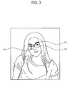
- FIG. 3 is a perspective view of stereoscopic glasses 200 according to an exemplary embodiment.
- the stereoscopic glasses 200 include a frame 210, a lens unit 220 and a second sensor 230.
- the stereoscopic glasses 200 may have any shape to include the lens unit 220.
- a groove may be formed at the inside of the frame 210 and prepared for the lens unit 220.
- the lens unit 220 is supported by the frame 210, and transmits light corresponding to the stereoscopic image displayed by the display apparatus 100, thereby providing a predetermined stereoscopic effect to a user.
- the lens unit 220 allows the user to feel the predetermined stereoscopic effect.
- the lens unit 220 is provided in accordance with a method of displaying a stereoscopic image by the display apparatus 100.
- the lens unit 220 includes a lens polarized in the same direction as polarized light corresponding to the stereoscopic image displayed by the display apparatus 100.
- the lens unit 220 includes a left-eye lens unit and a right-eye lens unit so that the left-eye lens unit and the right-eye lens unit can be selectively opened and closed in sync with the stereoscopic image displayed by the display apparatus 100. That is, when the display apparatus 100 displays a stereoscopic image, the view of a user's left eye or right eye is selectively opened or closed in accordance with which one of a left eye image and a right eye image is displayed. If the display apparatus displays the left eye image, the lens unit opens the view of the left eye and closes the view of the right eye. On the other hand, if the display apparatus displays the right eye image, the lens unit opens the view of the right eye and closes the view of the left eye.
- the stereoscopic glasses 200 may include a communication unit (not shown) to receive a shutter control signal by communicating with the display apparatus, and a shutter controller (not shown) to selectively open and close the lens unit 220 on the basis of the shutter control signal.
- the second sensor 230 can sense the user's viewing area within a 3D image displayed by the display unit 30.
- the second sensor 230 may include at least one of an eye tracing sensor and an eye tracing camera capable of tracing at least one of a position and a motion of a pupil of the user's eyeball.
- the second sensor 230 senses a position viewed by the user within a 3D image displayed by the display unit 30 by tracing at least one of the position and the motion of the user's eyeball, and thus generates information about the sensed viewing position, thereby transmitting the generated information to the display apparatus 100.
- the second sensor 230 determines the user's viewing direction with respect to a preset point on the display unit 30 by sensing the position of the user's eyeball, and thus generates information about the viewing position by determining the position viewed by the user within a 3D image displayed by the display unit 30 on the basis of the determined viewing direction, thereby transmitting the generated information to the display apparatus 100.
- FIG. 4 shows an example of adjusting depth through a signal processor 20 of a display apparatus 100 according to an exemplary embodiment.
- the display apparatus 100 in the present exemplary embodiment includes the sensor 40. While the display apparatus 100 displays a 3D image, the sensor 40 senses at least one of a position and a motion of a user's eyeball to sense a position viewed by the user within a currently displayed image. The sensor 40 may perform the sensing in response to a certain key input by a user through a remote controller. Using the sensed position viewed by the user, the sensor 40 thereby generates information about the viewing position. The sensor 40 may sense at least one of the position and the motion of the user's eyeball at every vertical sync period.
- a coordinate calculator 50 calculates coordinates corresponding to the viewing position on the display unit 30.
- a viewing area scope determiner 60 may determine a scope where coordinates having values approximating to a predetermined range are most distributed among the calculated coordinates collected for a predetermined period of time and corresponding to the viewing position. Thus, the viewing area scope determiner 60 determines a predetermined scope within an image on the display unit 30, corresponding to the scope where coordinates having values approximating to a predetermined range are most distributed, as the user's viewing area scope.
- an object of an elephant is bigger than an object of flowers displayed by the display unit 30.
- a user's viewing area determined by the sensor 40, the coordinate calculator 50, and the scope determiner 60 is an area A including the object of the flowers, and not an area B including the object of the elephant.
- a controller 80 controls a signal processor 20 to process the area A to have a depth effect different in level from those of areas other than the area A.
- the controller 80 may control the signal processor 20 to process an area A to have a depth effect having a predetermined level higher than those of the other areas except the area A. For example, if a 3D video signal including depth information is received through a receiver 10, a depth information extractor 21 extracts the depth information from the 3D video signal.
- controller 80 controls the signal processor 20 to process the area A to have a depth effect having a level higher than that of the extracted depth information, and the other areas except the area A to have a depth effect corresponding to the extracted depth information.
- the controller 80 may control the signal processor 20 to process areas other than the area A to have a depth effect having a predetermined level lower than that of the area A. For example, if a 3D video signal including depth information is received through the receiver 10, the depth information extractor 21 extracts the depth information from the 3D video signal. Moreover, the controller 80 controls the signal processor 20 to process the area A to have a depth effect corresponding to the extracted depth information, and the other areas except the area A to have a depth effect having a level lower than that of the extracted depth information.
- FIG. 5 shows an example of determining a viewing area in a display apparatus 100 according to an exemplary embodiment.
- the display apparatus 100 displays an image including a plurality of objects.
- the viewing area scope determiner 60 determines a scope E where the coordinates having values approximating to a predetermined range are most distributed, on the basis of the received outputs.
- the viewing area scope determiner 60 may determine a certain object A corresponding to the scope E as a user's viewing area scope.
- the controller 80 may control the signal processor 20 to process the object A to be different in a level of a depth effect as compared to other objects B.
- FIG. 6 shows an example of determining a viewing area in a display apparatus 100 according to another exemplary embodiment.
- an image displayed by the display apparatus 100 may be divided into a plurality of areas, i.e., N x M areas.
- the viewing area scope determiner 60 determines a scope E where the coordinates having values approximating to a predetermined range are most distributed, on the basis of the received outputs.
- the viewing area scope determiner 60 may determine one or more areas X corresponding to the scope E among the plurality of N by M divisional areas as a user's viewing area scope.
- the controller 80 may control a signal processor 20 to process the one or more areas X corresponding to the scope E to be different in level of a depth effect as compared to other areas.
- the different levels of the depth effect are the same as or similar to those described above with reference to FIG. 4 , and thus repetitive descriptions thereof are omitted herein.
- stereoscopic glasses and a display apparatus including the same in which an interest area where a user's view is determined to be fixed is processed to have a higher depth effect, and other areas are processed to have a depth effect lower than the depth effect of the interest area within a 3D image displayed by the display apparatus. Accordingly, the user's eyestrain can be remarkably reduced, thereby increasing convenience in 3D image viewing.
- an exemplary embodiment can also be embodied as computer-readable code on a computer-readable recording medium.
- the computer-readable recording medium is any data storage device that can store data that can be thereafter read by a computer system. Examples of the computer-readable recording medium include read-only memory (ROM), random-access memory (RAM), CD-ROMs, magnetic tapes, floppy disks, and optical data storage devices.
- the computer-readable recording medium can also be distributed over network-coupled computer systems so that the computer-readable code is stored and executed in a distributed fashion.
- an exemplary embodiment may be written as computer programs transmitted over a computer-readable transmission medium, such as a carrier wave, and received and implemented in general-use or special-purpose digital computers that execute the programs.
- one or more units of the display apparatus 100 and the stereoscopic glasses 200 can include a processor or microprocessor executing a computer program stored in a computer-readable medium.
Abstract
Description
- The present invention relates to stereoscopic glasses and a display apparatus including the same, and more particularly to stereoscopic glasses and a display apparatus including the same in which a depth effect of a three-dimensional (3D) image is adjustable to reduce eyestrain of a user.
- In general, a display apparatus that can display a 3D image represents depth information with regard to a wide scope provided by a depth map on a 3D display screen. In the case of an image including a plurality of objects, the depth information is represented with regard to all of the plurality of objects such that a user's eyes are distributed to all of the plurality of objects. Accordingly, the user may experience vertigo when 3D images of both eyes are combined in a brain, may feel eyestrain, etc., thereby increasing inconvenience.
- Accordingly, one or more exemplary embodiments provide stereoscopic glasses and a display apparatus including the same, in which a depth effect of a three-dimensional (3D) image is adjustable to reduce eyestrain of a user.
According to an aspect of an exemplary embodiment, there is provided a display apparatus including: a signal processor which processes a 3D video signal to have a predetermined depth effect; a display unit which displays the 3D image based on the processed video signal by the signal processor; and a controller which controls the signal processor to process a first area viewed by a user and a second area other than the first area to be different in a level of a depth effect within the 3D image displayed by the display unit. - The controller may control the signal processor to process the first area to have a depth effect having a predetermined level higher than that of the second area.
- The controller may control the signal processor to process the second area to have a depth effect having a predetermined level lower than that of the first area.
- The display apparatus may further include a sensor which senses the first area viewed by the user within the 3D image displayed by the display unit.
- The sensor may sense a position viewed by the user within the 3D image displayed by the display unit by tracing at least one of a position and a motion of an eyeball of the user, and may generate information about the sensed viewing position.
- The sensor may determine the user's viewing direction with respect to a preset point on the display unit by sensing a position of the user's eyeball, and may generate information about a viewing position by determining the position viewed by the user within the 3D image displayed by the display unit on the basis of the determined viewing direction.
- The display apparatus may further include a coordinate calculator which calculates coordinates corresponding to the viewing position on the display unit on the basis of information about the viewing position.
- The display apparatus may further include a viewing area scope determiner which determines a scope of the user's viewing area within the 3D image displayed by the display unit on the basis of the calculated coordinates.
- The viewing area scope determiner may determine a predetermined scope, where the user's viewing frequency is highest among viewing positions sensed for a predetermined period of time, as the scope of the user's viewing area.
The viewing area scope determiner may determine an object, where the user's viewing frequency is highest in at least one object included in the image, as the scope of the user's viewing area. - The 3D image displayed on the display unit may include a plurality of divisional areas, and the viewing area scope determiner may determine at least one area, where a viewing frequency is highest among the plurality of areas, as the scope of the user's viewing area.
- The display apparatus may further include a receiver which receives a video signal, wherein the signal processor includes a depth information extractor which extracts depth information from the 3D video signal when receiving the 3D video signal including the depth information through the receiver, and the controller controls the signal processor to process the second area to have a depth effect having a level lower than that of the extracted depth information.
- The display apparatus may further include a receiver which receives a video signal; and a storage unit which stores depth information for reconstructing a two-dimensional (2D) video signal received though the receiver into the 3D video signal, wherein the signal processor processes the received 2D video signal to be reconstructed as the 3D video signal on the basis of the depth information stored in the storage unit, and the controller controls the signal processor to process the second area to have a depth effect having a level lower than that of the stored depth information.
- The display apparatus may further include stereoscopic glasses including: a frame; a lens unit which is supported by the frame and transmits light corresponding to the 3D image displayed by the display unit to give a predetermined depth effect; and a sensor which senses the user's viewing area within the 3D image displayed by the display unit.
- The sensor of the stereoscopic glasses may sense a position viewed by the user within the 3D image displayed by the display unit by tracing at least one of a position and a motion of the user's eyeball, may generate information about the sensed viewing position, and may transmit the information to the display apparatus.
- The sensor of the stereoscopic glasses may determine the user's viewing direction with respect to a preset point on the display unit by sensing a position of the user's eyeball, may generate information about a viewing position by determining the position viewed by the user within the 3D image displayed by the display unit on the basis of the determined viewing direction, and may transmit the information to the display apparatus.
- According to an aspect of another exemplary embodiment, there is provided stereoscopic glasses for viewing a 3D image displayed by a display apparatus, the stereoscopic glasses including: a frame; a lens unit which is supported by the frame and transmits light corresponding to the 3D image displayed by the display apparatus to give a predetermined depth effect; and a sensor which senses a user's viewing area within the 3D image displayed by the display apparatus.
- The sensor may sense a position viewed by the user within the 3D image displayed by the display apparatus by tracing at least one of a position and a motion of the user's eyeball, may generate information about the sensed viewing position, and may transmit the information to the display apparatus.
- The sensor may determine the user's viewing direction with respect to a preset point on the display apparatus by sensing a position of the user's eyeball, may generate information about a viewing position by determining the position viewed by the user within the 3D image displayed by the display apparatus on the basis of the determined viewing direction, and may transmit the information to the display apparatus.
- According to an aspect of another exemplary embodiment, there is provided a method of processing a three-dimensional (3D) video signal, the method including: displaying, by a display unit, a 3D image based on the 3D video signal; and processing a first area determined to be viewed by a user and a second area that is not determined to be viewed by the user, of the 3D image displayed by the display unit, such that the first area is different in level of a depth effect than the second area.
- The above and/or other aspects will become apparent and more readily appreciated from the following description of exemplary embodiments, taken in conjunction with the accompanying drawings, in which:
-
FIG. 1 is a schematic view of a display system according to an exemplary embodiment; -
FIG. 2 is a control block diagram of adisplay apparatus 100 according to an exemplary embodiment; -
FIG. 3 is a perspective view ofstereoscopic glasses 200 according to an exemplary embodiment; -
FIG. 4 shows an example of adjusting a depth effect through asignal processor 20 of adisplay apparatus 100 according to an exemplary embodiment; -
FIG. 5 shows an example of determining a viewing area in adisplay apparatus 100 according to an exemplary embodiment; and -
FIG. 6 shows an example of determining a viewing area in adisplay apparatus 100 according to another exemplary embodiment. - Exemplary embodiments will now be described with reference to the accompanying drawings. Exemplary embodiments may be embodied in various forms without being limited to the exemplary embodiments set forth herein. Descriptions of well-known parts are omitted for clarity, and like reference numerals refer to like elements throughout. It is understood that expressions such as "at least one of," when preceding a list of elements, modify the entire list of elements and do not modify the individual elements of the list.
-
FIG. 1 is a schematic view of a display system according to an exemplary embodiment. Referring toFIG. 1 , the display system includes adisplay apparatus 100 capable of processing a video signal input from an exterior and displaying an image, andstereoscopic glasses 200 allowing a predetermined cubic effect or depth effect to be recognized corresponding to a three-dimensional (3D) video signal if an image displayed on thedisplay apparatus 100 is a 3D image. - The
display apparatus 100 according to the present exemplary embodimentcan process an area viewed by a user within the 3D image displayed on the display unit to have a depth effect different in level from areas other than the viewed area, so that a user's eyestrain can be remarkably reduced when the user views a 3D image, thereby increasing convenience. At this time, a sensor for sensing a viewing area of a user may be included in at least one of thedisplay apparatus 100 orstereoscopic glasses 200. - The
display apparatus 100 and thestereoscopic glasses 200 may employ polarization glasses or shutter glasses to achieve a stereoscopic effect. - For example, in the case of polarization glasses to provide a 3D image, the
display apparatus 100 may include a polarized filter and the polarization glasses are polarized in the same way as the polarized filter so that only an left image can be viewed by a left eye and only a right image can be viewed by a right eye, thereby achieving the stereoscopic effect. - Furthermore, by way of example, in the case of shutter glasses using a shutter to provide a 3D image, the display apparatus alternately displays left and right images so that a left glass can be open to a left image and a right glass can be open to a right image, thereby separating the left and right images and achieving the stereoscopic effect.
- The
display apparatus 100 may receive a video signal from an external video source (not shown), though it is understood that another exemplary embodiment is not limited in video source thereto. For example, thedisplay apparatus 100 may receive a video signal from various video sources such as a computer (not shown) that generates and locally provides a video signal through a central processing unit (not shown) and a graphic card (not shown), a server (not shown) that can provide a video signal through a network, a transmitter of a broadcasting station that can transmit a broadcasting signal through airwaves or a cable, etc. - The
display apparatus 100 receives a two-dimensional (2D) video signal or a 3D video signal from an exterior, and processes the received signal to be displayed as a 2D image or a 3D image. When thedisplay apparatus 100 receives a 2D video signal, the 2D video signal may be reconstructed as a 3D video signal on the basis of predetermined depth information, thereby displaying a 3D image. - In the case of the polarization glasses, the
display apparatus 100 separates the 3D image into left and right images and displays the images in a vertical line. Thus, if the 3D image is seen through the polarization glasses polarized in the same way as the polarized filter, only the left image is input to the left eye and only the right image is input to the right eye, thereby providing a stereoscopic effect. - In the case of the shutter glasses, the 3D image is divided into a left eye image corresponding to a user's left eye and a right eye image corresponding to a user's right eye. When the
display apparatus 100 receives the 3D video signal, the left eye image and the right eye image are alternately displayed per frame on the basis of the 3D video signal. At this time, thedisplay apparatus 100 transmits a sync signal to the shutter glasses in order to alternately open and close a left shutter unit and a right shutter unit of the shutter glasses in accordance with the frames for displaying the left eye image or the right eye image. While thedisplay apparatus 100 is displaying the 3D image, the shutter glasses selectively open or close a view of a user's left eye or right eye in accordance with which one of the left eye image or the right eye image is currently displayed. That is, when thedisplay apparatus 100 displays the left eye image, the shutter glasses open the view of the left eye but close the view of the right eye. On the other hand, when thedisplay apparatus 100 displays the right eye image, the shutter glasses open the view of the right eye but close the view of the left eye. -
FIG. 2 is a control block diagram of adisplay apparatus 100 according to an exemplary embodiment. - Referring to
FIG. 2 , thedisplay apparatus 100 includes areceiver 10, asignal processor 20, adisplay unit 30, asensor 40, acoordinate calculator 50, a viewing area scope determiner 60, astorage unit 70, and acontroller 80. - The
receiver 10 receives a video signal from an exterior and transmits the received video signal to thesignal processor 20, which can be achieved in various manners corresponding to a format of the received video signal and a type of thedisplay apparatus 100. The video signal may include at least one of a 2D video signal a 3D video signal, an audio signal, and a data signal. - For example, if the
display apparatus 100 is a television (TV), thereceiver 10 may wirelessly receive a radio frequency (RF) signal transmitted from a broadcast receiving apparatus, or may receive a video signal based on composite video, component video, super video, Syndicat des Constructeurs des Appareils Radiorecepteures et Televiseurs (SCART), high definition multimedia interface (HDMI), etc. Moreover, the receiver 110 may further include an antenna (not shown) and/or a tuner (not shown) for selecting a broadcasting channel.
For example, if thedisplay apparatus 100 is a monitor for a personal computer, thereceiver 10 may be realized by: D-SUB capable of transmitting RGB signals based on video graphics array (VGA); a digital video interactive-analog (DVI-A), a DVI-integrated digital/analog (DVI-I) and a DVI-digital (DVI-D) based on DVI; HDMI; etc. Furthermore, thereceiver 10 may be realized by a DisplayPort, a unified display interface (UDI), a wireless HD interface, etc. - The
signal processor 20 processes a predetermined 3D video signal to have a predetermined depth effect and transmits the processed 3D video signal to the display unit. - Moreover, when a 2D video signal is received through the
receiver 10, thesignal processor 20 can reconstruct the 2D video signal into a 3D video signal on the basis of predetermined depth information (e.g., stored in the storage unit 70), and can transmit the 3D video signal to thedisplay unit 30. - The
signal processor 20 may further include adepth information extractor 21 to extract depth information when receiving a 3D video signal including the depth information through thereceiver 10. Thus, the 3D video signal is processed to have the depth effect based on the depth information extracted by thedepth information extractor 21, and is then transmitted to thedisplay unit 30. - Furthermore, the
signal processor 20 may perform various image processes with respect to the video signal. For example, the image processes may include at least one of decoding and encoding, de-interlacing, frame refresh rate conversion, scaling, noise reduction, detail enhancement, line scanning, etc. - The
signal processor 20 processes the video signal into a plurality of horizontal scan lines per frame and scans the processed video signal to thedisplay unit 30. For example, thesignal processor 20 scans an image from a top to a bottom of a display area of thedisplay unit 30. When one frame is completely scanned, an image of the next frame is scanned leaving a preset non-scan period between the frames. - According to an exemplary embodiment, if the
display apparatus 100 uses the polarization glasses to display a stereoscopic image, thesignal processor 20 alternately and horizontally scans the video signals, respectively corresponding to the left eye image and the right eye image in the plurality of horizontal scan lines, to thedisplay unit 30 when receiving the video signal corresponding to the stereoscopic image from thereceiver 10. - According to another exemplary embodiment, if the
display apparatus 100 uses the shutter glasses to display a stereoscopic image, thesignal processor 20 sequentially and alternately scans the video signals, respectively corresponding to the left eye image and the right eye image within the video signal corresponding to the stereoscopic image transmitted through thereceiver 10, to thedisplay unit 30. - Thus, the left eye image and the right eye image are alternately displayed on the
display unit 30 during the non-scan period. In this case, thedisplay apparatus 100 may further include a communication unit (not shown) to communicate with the shutter glasses and a signal generator (not shown) to generate sync signals for the left eye image and the right eye image. Under control of the controller 80 (to be described later), the sync signal generated by the signal generator (not shown) is transmitted to the shutter glasses through the communication unit (not shown), and the shutter glasses alternately opens and closes lens units thereof. - The
signal processor 20 may process an audio signal received through thereceiver 10. Various audio processes with regard to the audio signal may be performed. For example, the audio processes may include at least one of digital conversion of an analog voice signal, amplification of an audio signal, output level control of an audio signal, frequency compensation of an audio signal, etc. - The
display unit 30 displays an image corresponding to a 3D video signal processed by thesignal processor 20. For example, in thedisplay unit 30, the plurality of horizontal scan lines are scanned from thesignal processor 20 and vertically arranged to thereby display one image frame. Thedisplay unit 30 includes a display panel (not shown) for displaying the image. The display panel (not shown) may include a liquid crystal display (LCD) panel having a liquid crystal layer, an organic light emitting display (OLED) panel having an organic light emitting layer, a plasma display panel (PDP), etc. - The
sensor 40 traces a position and/or motion of an eyeball, and senses a position viewed by a user within a 3D image displayed on thedisplay unit 30, thereby generating information about the sensed viewing position. - Specifically, the
sensor 40 may include at least one of an eye tracing sensor and an eye tracing camera for tracing at least one of a position and a motion of a pupil of the eyeball. Thus, thesensor 40 senses the position of a user's pupil and determines the user's viewing direction with respect to a preset point on thedisplay unit 30. - That is, an angle between the preset point on the
display unit 30 and the sensed position of the pupil is determined, and thus a user's viewing direction on an image displayed in thedisplay unit 30 is determined on the basis of the determined angle. According to the determined viewing direction, the position viewed by a user within the 3D image displayed by thedisplay unit 30 is determined, thereby generating information about the viewing position. - The
sensor 40 may trace at least one of the position and the motion of the user's pupil at every vertical sync period of a video signal. - The coordinate
calculator 50 can calculate coordinates corresponding to the viewing position on the display unit on the basis of the information about the viewing position generated by thesensor 40. Corresponding to the viewing position, it is possible to calculate the coordinates of an image pixel displayed on thedisplay unit 30. - The viewing
area scope determiner 60 can determine a scope of the user's viewing area within the 3D image displayed by thedisplay unit 30 based on the coordinates calculated by the coordinatecalculator 50. - The viewing
area scope determiner 60 may determine, as the user's viewing area scope, a predetermined scope of at least one position where a user's viewing frequency is highest among the viewing positions sensed for a predetermined time. - On the basis of information about the user's viewing positions generated in the
sensor 40 for a preset period of time, the coordinatecalculator 50 calculates a plurality of coordinates. Further, a scope where coordinates having values approximating to a predetermined range are most distributed may be determined among the plurality of coordinates. Thus, a predetermined scope within an image on thedisplay unit 30, corresponding to a scope where the plurality of coordinates having values approximating to the predetermined range are most distributed, may be determined as the user's viewing area scope. - Furthermore, the viewing
area scope determiner 60 may determine a certain object, to which the scope where the coordinates having values approximating to the predetermine range are most distributed belongs, as the user's viewing area scope. - That is, in the case that at least one object is included in an image, an object corresponding to the scope where the coordinates having the values approximating to a predetermined range are most distributed for a preset time is selected among the objects, and the selected object is determined as the user's viewing area scope.
- For example, if an image includes an object having a human shape and the scope where the coordinates having values approximating to a predetermined range are most distributed for a preset period of time is a head of the human shape, the whole object having the human shape may be determined as the user's viewing area scope.
- Moreover, if an image displayed in the
display unit 30 includes a plurality of divisional areas, the viewingarea scope determiner 60 may determine at least one area among the plurality of areas, which corresponds to a scope where the coordinates having the values approximating to the predetermined range are most distributed, as the user's viewing area scope. - For example, in the case where an image displayed on the display unit includes N x M areas (where N and M are integers), at least one area corresponding to the scope where the coordinates having the values approximating to the predetermined range may be determined as the user's viewing area scope among the plurality of areas.
- The
storage unit 70 may store depth information used to reconstruct a 2D video signal into a 3D video signal when receiving the 2D video signal through thereceiver 10. - The
controller 80 may control thesignal processor 20 to process an area, being viewed by the user among 3D images displayed by thedisplay unit 30, to have a depth effect different in level from those of other areas not being viewed by the user. - If the user's viewing area scope is determined within the 3D image displayed by the
display unit 30 by thesensor 40, the coordinatecalculator 50 and the viewingarea scope determiner 60, thecontroller 80 may control thesignal processor 20 to process the determined viewing area scope to have a depth effect different in level from those of areas other than the determined viewing area scope. - According to an exemplary embodiment, the
controller 80 may control thesignal processor 20 to process the determined viewing area scope to have a depth effect having a level higher than those of other areas except the determined viewing area scope. - Alternatively or additionally, the
controller 80 may control thesignal processor 20 to process areas except the determined viewing area scope to have a depth effect having a level lower than that of the determined viewing area scope. - If a 3D video signal having depth information is received through the
receiver 10, thedepth information extractor 21 extracts the depth information from the 3D video signal. Thecontroller 80 may control thesignal processor 20 so that a viewing area scope determined as being viewed by the user can be processed to have a depth effect corresponding to the extracted depth information but the other areas except the viewing area scope can be processed to have a depth effect having a predetermined level lower than that corresponding to the depth information. - Also, a 2D video signal may be received through the
receiver 10 and reconstructed by thesignal processor 20 into a 3D video signal on the basis of depth information (e.g., stored in the storage unit 70), so that an image corresponding to the 3D video signal can be displayed on thedisplay unit 30. In this case, thecontroller 80 may control thesignal processor 20 so that a viewing area scope determined as being viewed by the user can be processed to have a depth effect corresponding to the depth information but the areas other then the viewing area scope can be processed to have a depth effect having a predetermined level lower than that corresponding to the depth information. - According to an exemplary embodiment, if the
sensor 40 is provided in thedisplay apparatus 100, the stereoscopic glasses 200 (refer toFIG. 3 ) provided along with thedisplay apparatus 100 may not include the sensor. - According to another exemplary embodiment, the stereoscopic glasses 200 (refer to
FIG. 3 ) may include the sensor. In this case, thesensor 40 may or may not be provided in thedisplay apparatus 100,
FIG. 3 is a perspective view ofstereoscopic glasses 200 according to an exemplary embodiment. - Referring to
FIG. 3 , thestereoscopic glasses 200 include aframe 210, alens unit 220 and asecond sensor 230. - The
stereoscopic glasses 200 may have any shape to include thelens unit 220. - Furthermore, a groove may be formed at the inside of the
frame 210 and prepared for thelens unit 220. - The
lens unit 220 is supported by theframe 210, and transmits light corresponding to the stereoscopic image displayed by thedisplay apparatus 100, thereby providing a predetermined stereoscopic effect to a user. - The
lens unit 220 allows the user to feel the predetermined stereoscopic effect. - Thus, the
lens unit 220 is provided in accordance with a method of displaying a stereoscopic image by thedisplay apparatus 100. - If the
display apparatus 100 according to an exemplary embodiment employs polarization glasses for displaying a stereoscopic image, thelens unit 220 includes a lens polarized in the same direction as polarized light corresponding to the stereoscopic image displayed by thedisplay apparatus 100. - If the
display apparatus 100 according to another exemplary embodiment employs shutter glasses for displaying a stereoscopic image, thelens unit 220 includes a left-eye lens unit and a right-eye lens unit so that the left-eye lens unit and the right-eye lens unit can be selectively opened and closed in sync with the stereoscopic image displayed by thedisplay apparatus 100. That is, when thedisplay apparatus 100 displays a stereoscopic image, the view of a user's left eye or right eye is selectively opened or closed in accordance with which one of a left eye image and a right eye image is displayed. If the display apparatus displays the left eye image, the lens unit opens the view of the left eye and closes the view of the right eye. On the other hand, if the display apparatus displays the right eye image, the lens unit opens the view of the right eye and closes the view of the left eye. - Thus, if the
stereoscopic glasses 200 are achieved by the shutter glasses, thestereoscopic glasses 200 may include a communication unit (not shown) to receive a shutter control signal by communicating with the display apparatus, and a shutter controller (not shown) to selectively open and close thelens unit 220 on the basis of the shutter control signal. - The
second sensor 230 can sense the user's viewing area within a 3D image displayed by thedisplay unit 30. Specifically, thesecond sensor 230 may include at least one of an eye tracing sensor and an eye tracing camera capable of tracing at least one of a position and a motion of a pupil of the user's eyeball. - The
second sensor 230 senses a position viewed by the user within a 3D image displayed by thedisplay unit 30 by tracing at least one of the position and the motion of the user's eyeball, and thus generates information about the sensed viewing position, thereby transmitting the generated information to thedisplay apparatus 100. - The
second sensor 230 determines the user's viewing direction with respect to a preset point on thedisplay unit 30 by sensing the position of the user's eyeball, and thus generates information about the viewing position by determining the position viewed by the user within a 3D image displayed by thedisplay unit 30 on the basis of the determined viewing direction, thereby transmitting the generated information to thedisplay apparatus 100. -
FIG. 4 shows an example of adjusting depth through asignal processor 20 of adisplay apparatus 100 according to an exemplary embodiment. - The
display apparatus 100 in the present exemplary embodiment includes thesensor 40. While thedisplay apparatus 100 displays a 3D image, thesensor 40 senses at least one of a position and a motion of a user's eyeball to sense a position viewed by the user within a currently displayed image. Thesensor 40 may perform the sensing in response to a certain key input by a user through a remote controller. Using the sensed position viewed by the user, thesensor 40 thereby generates information about the viewing position. Thesensor 40 may sense at least one of the position and the motion of the user's eyeball at every vertical sync period. - On the basis of the generated information about the user's viewing position, a coordinate
calculator 50 calculates coordinates corresponding to the viewing position on thedisplay unit 30. - A viewing
area scope determiner 60 may determine a scope where coordinates having values approximating to a predetermined range are most distributed among the calculated coordinates collected for a predetermined period of time and corresponding to the viewing position. Thus, the viewingarea scope determiner 60 determines a predetermined scope within an image on thedisplay unit 30, corresponding to the scope where coordinates having values approximating to a predetermined range are most distributed, as the user's viewing area scope. - Referring to
FIG. 4 , an object of an elephant is bigger than an object of flowers displayed by thedisplay unit 30. However, a user's viewing area determined by thesensor 40, the coordinatecalculator 50, and thescope determiner 60 is an area A including the object of the flowers, and not an area B including the object of the elephant. Thus, acontroller 80 controls asignal processor 20 to process the area A to have a depth effect different in level from those of areas other than the area A. - According to an exemplary embodiment, the
controller 80 may control thesignal processor 20 to process an area A to have a depth effect having a predetermined level higher than those of the other areas except the area A. For example, if a 3D video signal including depth information is received through areceiver 10, adepth information extractor 21 extracts the depth information from the 3D video signal. - Moreover, the
controller 80 controls thesignal processor 20 to process the area A to have a depth effect having a level higher than that of the extracted depth information, and the other areas except the area A to have a depth effect corresponding to the extracted depth information. - According to another exemplary embodiment, the
controller 80 may control thesignal processor 20 to process areas other than the area A to have a depth effect having a predetermined level lower than that of the area A. For example, if a 3D video signal including depth information is received through thereceiver 10, thedepth information extractor 21 extracts the depth information from the 3D video signal. Moreover, thecontroller 80 controls thesignal processor 20 to process the area A to have a depth effect corresponding to the extracted depth information, and the other areas except the area A to have a depth effect having a level lower than that of the extracted depth information. -
FIG. 5 shows an example of determining a viewing area in adisplay apparatus 100 according to an exemplary embodiment. - Referring to
FIG. 5 , thedisplay apparatus 100 displays an image including a plurality of objects. When outputs of asensor 40 and a coordinatecalculator 50 are transmitted to a viewingarea scope determiner 60, the viewingarea scope determiner 60 determines a scope E where the coordinates having values approximating to a predetermined range are most distributed, on the basis of the received outputs. In particular, the viewingarea scope determiner 60 may determine a certain object A corresponding to the scope E as a user's viewing area scope. - Accordingly, the
controller 80 may control thesignal processor 20 to process the object A to be different in a level of a depth effect as compared to other objects B. - The different levels of the depth effect are the same as or similar to those described above with reference to
FIG. 4 , and thus repetitive descriptions thereof are omittd herein. -
FIG. 6 shows an example of determining a viewing area in adisplay apparatus 100 according to another exemplary embodiment. - Referring to
FIG. 6 , an image displayed by thedisplay apparatus 100 may be divided into a plurality of areas, i.e., N x M areas. When outputs of asensor 40 and a coordinatecalculator 50 are transmitted to a viewingarea scope determiner 60, the viewingarea scope determiner 60 determines a scope E where the coordinates having values approximating to a predetermined range are most distributed, on the basis of the received outputs. - For example, the viewing
area scope determiner 60 may determine one or more areas X corresponding to the scope E among the plurality of N by M divisional areas as a user's viewing area scope. - Accordingly, the
controller 80 may control asignal processor 20 to process the one or more areas X corresponding to the scope E to be different in level of a depth effect as compared to other areas. The different levels of the depth effect are the same as or similar to those described above with reference toFIG. 4 , and thus repetitive descriptions thereof are omitted herein. - As described above, according to one or more exemplary embodiment, there are provided stereoscopic glasses and a display apparatus including the same in which an interest area where a user's view is determined to be fixed is processed to have a higher depth effect, and other areas are processed to have a depth effect lower than the depth effect of the interest area within a 3D image displayed by the display apparatus. Accordingly, the user's eyestrain can be remarkably reduced, thereby increasing convenience in 3D image viewing.
- While not restricted thereto, an exemplary embodiment can also be embodied as computer-readable code on a computer-readable recording medium. The computer-readable recording medium is any data storage device that can store data that can be thereafter read by a computer system. Examples of the computer-readable recording medium include read-only memory (ROM), random-access memory (RAM), CD-ROMs, magnetic tapes, floppy disks, and optical data storage devices.
- The computer-readable recording medium can also be distributed over network-coupled computer systems so that the computer-readable code is stored and executed in a distributed fashion. Also, an exemplary embodiment may be written as computer programs transmitted over a computer-readable transmission medium, such as a carrier wave, and received and implemented in general-use or special-purpose digital computers that execute the programs. Moreover, in an exemplary embodiment, one or more units of the
display apparatus 100 and thestereoscopic glasses 200 can include a processor or microprocessor executing a computer program stored in a computer-readable medium. - Although a few exemplary embodiments have been shown and described, it will be appreciated by those skilled in the art that changes may be made in these exemplary embodiments without departing from the principles of the inventive concept, the scope of which is defined in the appended claims.
Claims (15)
- A display apparatus comprising:a signal processor which processes a three-dimensional (3D) video signal to have a predetermined depth effect;a display unit which displays a 3D image based on the processed video signal processed by the signal processor; anda controller which controls the signal processor to process a first area determined to be viewed by a user and a second area that is not determined to be viewed by the user, of the 3D image displayed by the display unit, such that the first area is different in level of a depth effect than the second area.
- The display apparatus according to claim 1, wherein the controller controls the signal processor to process the first area to have a depth effect that is a predetermined level higher than a depth effect of the second area.
- The display apparatus according to claim 1, wherein the controller controls the signal processor to process the second area to have a depth effect that is a predetermined level lower than a depth effect of the first area.
- The display apparatus according to claim 1, further comprising a sensor which senses the first area viewed by the user within the 3D image displayed by the display unit.
- The display apparatus according to claim 4, wherein the sensor senses a position viewed by the user within the 3D image displayed by the display unit by tracing at least one of a position and a motion of an eyeball of the user, and generates information about the sensed viewing position.
- The display apparatus according to claim 4, wherein the sensor determines a viewing direction of the user with respect to a preset point on the display unit by sensing a position of an eyeball of the user, and generates information about a viewing position by determining a position viewed by the user within the 3D image displayed by the display unit according to the determined viewing direction.
- The display apparatus according to claim 5 or claim 6, further comprising a coordinate calculator which calculates one or more coordinates corresponding to the viewing position on the display unit according to the information about the viewing position.
- The display apparatus according to claim 7, further comprising a viewing area scope determiner which determines a scope of a viewing area of the user within the 3D image displayed by the display unit according to the one or more calculated coordinates.
- The display apparatus according to claim 8, wherein the viewing area scope determiner determines, as the scope of the viewing area of the user, a scope where a viewing frequency of the user is highest among viewing positions sensed for a predetermined period of time.
- The display apparatus according to claim 9, wherein the viewing area scope determiner determines, as the scope of the viewing area of the user, an object where a viewing frequency of the user is highest from among at least one object included in the 3D image.
- The display apparatus according to claim 9, wherein:the 3D image displayed by the display unit comprises a plurality of divisional areas; andthe viewing area scope determiner determines, as the scope of the viewing area of the user, at least one area where a viewing frequency of the user is highest among the plurality of divisional areas.
- The display apparatus according to claim 1, further comprising a receiver which receives the 3D video signal,
wherein the signal processor comprises a depth information extractor which extracts depth information from the received 3D video signal when the received 3D video signal comprises the depth information, and
the controller controls the signal processor to process the second area to have a depth effect having a level lower than a depth effect for the second area based on the extracted depth information. - Stereoscopic glasses for viewing a three-dimensional (3D) image displayed by a display apparatus, the stereoscopic glasses comprising:a lens unit which transmits light corresponding to the 3D image displayed by the display apparatus to provide a predetermined depth effect;a frame which supports the lens unit; anda sensor which senses a first area viewed by a user within the 3D image displayed by the display apparatus.
- The stereoscopic glasses according to claim 13, wherein the sensor senses a position viewed by the user within the 3D image displayed by the display apparatus by tracing at least one of a position and a motion of an eyeball of the user, generates information about the sensed viewing position, and transmits the generated information to the display apparatus.
- The stereoscopic glasses according to claim 14, wherein the sensor determines a viewing direction of the user with respect to a preset point on the display unit by sensing a position of an eyeball of the user, generates information about a viewing position by determining a position viewed by the user within the 3D image displayed by the display apparatus according to the determined viewing direction, and transmits the generated information to the display apparatus.
Applications Claiming Priority (1)
| Application Number | Priority Date | Filing Date | Title |
|---|---|---|---|
| KR1020100066024A KR20120005328A (en) | 2010-07-08 | 2010-07-08 | Stereoscopic glasses and display apparatus including the same |
Publications (2)
| Publication Number | Publication Date |
|---|---|
| EP2405664A2 true EP2405664A2 (en) | 2012-01-11 |
| EP2405664A3 EP2405664A3 (en) | 2012-05-30 |
Family
ID=43754964
Family Applications (1)
| Application Number | Title | Priority Date | Filing Date |
|---|---|---|---|
| EP11156297A Withdrawn EP2405664A3 (en) | 2010-07-08 | 2011-02-28 | Stereoscopic Glasses and Display Apparatus Including the Same |
Country Status (4)
| Country | Link |
|---|---|
| US (1) | US8872901B2 (en) |
| EP (1) | EP2405664A3 (en) |
| JP (1) | JP2012019509A (en) |
| KR (1) | KR20120005328A (en) |
Cited By (2)
| Publication number | Priority date | Publication date | Assignee | Title |
|---|---|---|---|---|
| US20140055578A1 (en) * | 2012-08-21 | 2014-02-27 | Boe Technology Group Co., Ltd. | Apparatus for adjusting displayed picture, display apparatus and display method |
| EP2974301A4 (en) * | 2013-03-12 | 2016-10-26 | Intel Corp | Techniques for automated evaluation of 3d visual content |
Families Citing this family (17)
| Publication number | Priority date | Publication date | Assignee | Title |
|---|---|---|---|---|
| EP2525581A3 (en) * | 2011-05-17 | 2013-10-23 | Samsung Electronics Co., Ltd. | Apparatus and Method for Converting 2D Content into 3D Content, and Computer-Readable Storage Medium Thereof |
| KR101890927B1 (en) * | 2011-06-28 | 2018-09-28 | 엘지디스플레이 주식회사 | Stereoscopic Image Display Device and Driving Method thereof |
| KR101334301B1 (en) * | 2012-07-25 | 2013-11-27 | 용성규 | Cup for microwave having heating element |
| CN103353677B (en) | 2013-06-28 | 2015-03-11 | 北京智谷睿拓技术服务有限公司 | Imaging device and method thereof |
| CN103353663B (en) | 2013-06-28 | 2016-08-10 | 北京智谷睿拓技术服务有限公司 | Imaging adjusting apparatus and method |
| CN103353667B (en) * | 2013-06-28 | 2015-10-21 | 北京智谷睿拓技术服务有限公司 | Imaging adjustment Apparatus and method for |
| CN103424891B (en) | 2013-07-31 | 2014-12-17 | 北京智谷睿拓技术服务有限公司 | Imaging device and method |
| CN103439801B (en) | 2013-08-22 | 2016-10-26 | 北京智谷睿拓技术服务有限公司 | Sight protectio imaging device and method |
| CN103605208B (en) | 2013-08-30 | 2016-09-28 | 北京智谷睿拓技术服务有限公司 | content projection system and method |
| CN103500331B (en) | 2013-08-30 | 2017-11-10 | 北京智谷睿拓技术服务有限公司 | Based reminding method and device |
| US20150116197A1 (en) * | 2013-10-24 | 2015-04-30 | Johnson Controls Technology Company | Systems and methods for displaying three-dimensional images on a vehicle instrument console |
| KR102219953B1 (en) * | 2014-07-15 | 2021-02-25 | 삼성디스플레이 주식회사 | Method of displaying an image and image display device for performing the same |
| KR20160031641A (en) * | 2014-09-12 | 2016-03-23 | 삼성디스플레이 주식회사 | Shutter glasses, driving method for shutter glasses and display device uigng the same |
| KR20160042277A (en) * | 2014-10-08 | 2016-04-19 | 삼성디스플레이 주식회사 | 3d glasses and method of driving the same |
| US10333948B2 (en) * | 2016-02-29 | 2019-06-25 | Palo Alto Networks, Inc. | Alerting and tagging using a malware analysis platform for threat intelligence made actionable |
| GB2548346B (en) * | 2016-03-11 | 2020-11-18 | Sony Interactive Entertainment Europe Ltd | Image processing method and apparatus |
| KR20200057480A (en) | 2018-11-16 | 2020-05-26 | 삼성전자주식회사 | Apparatus for controlling augmented reality, method of implementing augmented reality using the same, and system of implementing augmented reality including the same |
Family Cites Families (16)
| Publication number | Priority date | Publication date | Assignee | Title |
|---|---|---|---|---|
| JPH03109030A (en) * | 1989-09-22 | 1991-05-09 | Canon Inc | Noting point detector |
| JP2974383B2 (en) * | 1990-08-21 | 1999-11-10 | キヤノン株式会社 | Gaze detection device and device having gaze detection device |
| US5265199A (en) * | 1991-05-22 | 1993-11-23 | Silicon Graphics, Inc. | Method and apparatus for accomplishing Z-buffering by prediction |
| JPH05158132A (en) * | 1991-11-18 | 1993-06-25 | Nikon Corp | Main object information recording camera |
| JPH0756517A (en) * | 1993-08-20 | 1995-03-03 | Matsushita Electric Ind Co Ltd | Spectacle type image display device |
| JP3089306B2 (en) * | 1993-08-26 | 2000-09-18 | 松下電器産業株式会社 | Stereoscopic imaging and display device |
| EP0641132B1 (en) * | 1993-08-26 | 1999-04-14 | Matsushita Electric Industrial Co., Ltd. | Stereoscopic image pickup apparatus |
| JP3226153B2 (en) * | 1996-03-18 | 2001-11-05 | シャープ株式会社 | Multimedia data display device |
| JP3802630B2 (en) * | 1996-12-28 | 2006-07-26 | オリンパス株式会社 | Stereoscopic image generating apparatus and stereoscopic image generating method |
| JPH11155154A (en) * | 1997-11-19 | 1999-06-08 | Toshiba Corp | Stereoscopic video processing unit |
| US6429867B1 (en) * | 1999-03-15 | 2002-08-06 | Sun Microsystems, Inc. | System and method for generating and playback of three-dimensional movies |
| JP4101434B2 (en) * | 2000-05-18 | 2008-06-18 | 日本放送協会 | Transmission control device |
| WO2005043218A1 (en) * | 2003-10-30 | 2005-05-12 | Brother Kogyo Kabushiki Kaisha | Image display device |
| US8537204B2 (en) * | 2004-07-08 | 2013-09-17 | Gyoung Il Cho | 3D television broadcasting system |
| US20070007301A1 (en) * | 2005-06-29 | 2007-01-11 | Kaplan Jeffrey S | Pill dispensing container elements and methods |
| RU2411690C2 (en) | 2005-12-02 | 2011-02-10 | Конинклейке Филипс Электроникс Н.В. | Method and device for displaying stereoscopic images, method of generating 3d image data from input 2d image data, and device for generating 3d image data from input 2d image data |
-
2010
- 2010-07-08 KR KR1020100066024A patent/KR20120005328A/en not_active Application Discontinuation
-
2011
- 2011-02-28 EP EP11156297A patent/EP2405664A3/en not_active Withdrawn
- 2011-03-01 US US13/037,414 patent/US8872901B2/en not_active Expired - Fee Related
- 2011-05-23 JP JP2011114664A patent/JP2012019509A/en active Pending
Non-Patent Citations (1)
| Title |
|---|
| None |
Cited By (4)
| Publication number | Priority date | Publication date | Assignee | Title |
|---|---|---|---|---|
| US20140055578A1 (en) * | 2012-08-21 | 2014-02-27 | Boe Technology Group Co., Ltd. | Apparatus for adjusting displayed picture, display apparatus and display method |
| EP2701390A3 (en) * | 2012-08-21 | 2015-09-16 | Boe Technology Group Co. Ltd. | Apparatus for adjusting displayed picture, display apparatus and display method |
| US9451242B2 (en) * | 2012-08-21 | 2016-09-20 | Boe Technology Group Co., Ltd. | Apparatus for adjusting displayed picture, display apparatus and display method |
| EP2974301A4 (en) * | 2013-03-12 | 2016-10-26 | Intel Corp | Techniques for automated evaluation of 3d visual content |
Also Published As
| Publication number | Publication date |
|---|---|
| US20120007959A1 (en) | 2012-01-12 |
| US8872901B2 (en) | 2014-10-28 |
| KR20120005328A (en) | 2012-01-16 |
| EP2405664A3 (en) | 2012-05-30 |
| JP2012019509A (en) | 2012-01-26 |
Similar Documents
| Publication | Publication Date | Title |
|---|---|---|
| US8872901B2 (en) | Stereoscopic glasses and display apparatus including the same | |
| US9414041B2 (en) | Method for changing play mode, method for changing display mode, and display apparatus and 3D image providing system using the same | |
| CN102196285B (en) | The method of adjustment 3D rendering quality and 3D display device | |
| US20130038611A1 (en) | Image conversion device | |
| US20120127273A1 (en) | Image processing apparatus and control method thereof | |
| US8854438B2 (en) | Display system, display apparatus and control method thereof | |
| US8749617B2 (en) | Display apparatus, method for providing 3D image applied to the same, and system for providing 3D image | |
| KR101911250B1 (en) | Apparatus for processing a three-dimensional image and method for adjusting location of sweet spot for viewing multi-view image | |
| US20110261451A1 (en) | Stereoscopic glasses and display apparatus including the same | |
| CN102918855A (en) | Method and apparaus for making intelligent use of active space in frame packing format | |
| EP2337370A2 (en) | 3D glasses, method for controlling 3D glasses, and method for controlling power applied thereto | |
| US9247240B2 (en) | Three-dimensional glasses, three-dimensional image display apparatus, and method for driving the three-dimensional glasses and the three-dimensional image display apparatus | |
| KR20120032321A (en) | Display apparatus and method for processing image applied to the same | |
| US20110254933A1 (en) | Shutter glasses, display apparatus including the same, and control method thereof | |
| KR20120052091A (en) | Computer, monitor, and method for providing 3d image | |
| US8547418B2 (en) | Method and system for processing and displaying video in three dimensions using a liquid crystal display | |
| US20120224035A1 (en) | Electronic apparatus and image processing method | |
| EP2398244A2 (en) | Image processing apparatus and control method of the same | |
| KR20110098253A (en) | Display system and control method thereof | |
| KR20150039463A (en) | A 3 dimension display device and 3 dimension image processing method | |
| US20120057004A1 (en) | Display apparatus and method of controlling the same, shutter glasses and method of controlling the same, and display system | |
| CN102892023A (en) | Display apparatus with 3D structure and control method thereof | |
| US8736602B2 (en) | Display apparatus and control method thereof | |
| KR20130019273A (en) | Method for outputting 3-dimension image and display apparatus thereof | |
| KR20110062983A (en) | Display apparatus for displaying gui which sets adjustment element for 3 dimensional effect of 3d image and method for providing graphic user interface applied to the same |
Legal Events
| Date | Code | Title | Description |
|---|---|---|---|
| AK | Designated contracting states |
Kind code of ref document: A2 Designated state(s): AL AT BE BG CH CY CZ DE DK EE ES FI FR GB GR HR HU IE IS IT LI LT LU LV MC MK MT NL NO PL PT RO RS SE SI SK SM TR |
|
| AX | Request for extension of the european patent |
Extension state: BA ME |
|
| PUAI | Public reference made under article 153(3) epc to a published international application that has entered the european phase |
Free format text: ORIGINAL CODE: 0009012 |
|
| PUAL | Search report despatched |
Free format text: ORIGINAL CODE: 0009013 |
|
| AK | Designated contracting states |
Kind code of ref document: A3 Designated state(s): AL AT BE BG CH CY CZ DE DK EE ES FI FR GB GR HR HU IE IS IT LI LT LU LV MC MK MT NL NO PL PT RO RS SE SI SK SM TR |
|
| AX | Request for extension of the european patent |
Extension state: BA ME |
|
| RIC1 | Information provided on ipc code assigned before grant |
Ipc: H04N 13/04 20060101ALI20120426BHEP Ipc: H04N 13/00 20060101AFI20120426BHEP |
|
| RAP1 | Party data changed (applicant data changed or rights of an application transferred) |
Owner name: SAMSUNG ELECTRONICS CO., LTD. |
|
| 17P | Request for examination filed |
Effective date: 20121130 |
|
| STAA | Information on the status of an ep patent application or granted ep patent |
Free format text: STATUS: THE APPLICATION IS DEEMED TO BE WITHDRAWN |
|
| 18D | Application deemed to be withdrawn |
Effective date: 20170901 |