EP2405224A1 - Process for manufacturing a brazed heat exchanger - Google Patents
Process for manufacturing a brazed heat exchanger Download PDFInfo
- Publication number
- EP2405224A1 EP2405224A1 EP10169012A EP10169012A EP2405224A1 EP 2405224 A1 EP2405224 A1 EP 2405224A1 EP 10169012 A EP10169012 A EP 10169012A EP 10169012 A EP10169012 A EP 10169012A EP 2405224 A1 EP2405224 A1 EP 2405224A1
- Authority
- EP
- European Patent Office
- Prior art keywords
- tubular
- tank
- separator
- brazing
- metal sheet
- Prior art date
- Legal status (The legal status is an assumption and is not a legal conclusion. Google has not performed a legal analysis and makes no representation as to the accuracy of the status listed.)
- Granted
Links
Images


Classifications
-
- F—MECHANICAL ENGINEERING; LIGHTING; HEATING; WEAPONS; BLASTING
- F28—HEAT EXCHANGE IN GENERAL
- F28F—DETAILS OF HEAT-EXCHANGE AND HEAT-TRANSFER APPARATUS, OF GENERAL APPLICATION
- F28F9/00—Casings; Header boxes; Auxiliary supports for elements; Auxiliary members within casings
- F28F9/02—Header boxes; End plates
- F28F9/0202—Header boxes having their inner space divided by partitions
- F28F9/0204—Header boxes having their inner space divided by partitions for elongated header box, e.g. with transversal and longitudinal partitions
- F28F9/0209—Header boxes having their inner space divided by partitions for elongated header box, e.g. with transversal and longitudinal partitions having only transversal partitions
- F28F9/0212—Header boxes having their inner space divided by partitions for elongated header box, e.g. with transversal and longitudinal partitions having only transversal partitions the partitions being separate elements attached to header boxes
-
- B—PERFORMING OPERATIONS; TRANSPORTING
- B21—MECHANICAL METAL-WORKING WITHOUT ESSENTIALLY REMOVING MATERIAL; PUNCHING METAL
- B21C—MANUFACTURE OF METAL SHEETS, WIRE, RODS, TUBES OR PROFILES, OTHERWISE THAN BY ROLLING; AUXILIARY OPERATIONS USED IN CONNECTION WITH METAL-WORKING WITHOUT ESSENTIALLY REMOVING MATERIAL
- B21C37/00—Manufacture of metal sheets, bars, wire, tubes or like semi-manufactured products, not otherwise provided for; Manufacture of tubes of special shape
- B21C37/06—Manufacture of metal sheets, bars, wire, tubes or like semi-manufactured products, not otherwise provided for; Manufacture of tubes of special shape of tubes or metal hoses; Combined procedures for making tubes, e.g. for making multi-wall tubes
- B21C37/08—Making tubes with welded or soldered seams
- B21C37/0815—Making tubes with welded or soldered seams without continuous longitudinal movement of the sheet during the bending operation
-
- B—PERFORMING OPERATIONS; TRANSPORTING
- B21—MECHANICAL METAL-WORKING WITHOUT ESSENTIALLY REMOVING MATERIAL; PUNCHING METAL
- B21C—MANUFACTURE OF METAL SHEETS, WIRE, RODS, TUBES OR PROFILES, OTHERWISE THAN BY ROLLING; AUXILIARY OPERATIONS USED IN CONNECTION WITH METAL-WORKING WITHOUT ESSENTIALLY REMOVING MATERIAL
- B21C37/00—Manufacture of metal sheets, bars, wire, tubes or like semi-manufactured products, not otherwise provided for; Manufacture of tubes of special shape
- B21C37/06—Manufacture of metal sheets, bars, wire, tubes or like semi-manufactured products, not otherwise provided for; Manufacture of tubes of special shape of tubes or metal hoses; Combined procedures for making tubes, e.g. for making multi-wall tubes
- B21C37/15—Making tubes of special shape; Making tube fittings
- B21C37/156—Making tubes with wall irregularities
- B21C37/157—Perforations
-
- B—PERFORMING OPERATIONS; TRANSPORTING
- B23—MACHINE TOOLS; METAL-WORKING NOT OTHERWISE PROVIDED FOR
- B23K—SOLDERING OR UNSOLDERING; WELDING; CLADDING OR PLATING BY SOLDERING OR WELDING; CUTTING BY APPLYING HEAT LOCALLY, e.g. FLAME CUTTING; WORKING BY LASER BEAM
- B23K1/00—Soldering, e.g. brazing, or unsoldering
- B23K1/0008—Soldering, e.g. brazing, or unsoldering specially adapted for particular articles or work
- B23K1/0012—Brazing heat exchangers
-
- B—PERFORMING OPERATIONS; TRANSPORTING
- B23—MACHINE TOOLS; METAL-WORKING NOT OTHERWISE PROVIDED FOR
- B23P—METAL-WORKING NOT OTHERWISE PROVIDED FOR; COMBINED OPERATIONS; UNIVERSAL MACHINE TOOLS
- B23P15/00—Making specific metal objects by operations not covered by a single other subclass or a group in this subclass
- B23P15/26—Making specific metal objects by operations not covered by a single other subclass or a group in this subclass heat exchangers or the like
-
- F—MECHANICAL ENGINEERING; LIGHTING; HEATING; WEAPONS; BLASTING
- F28—HEAT EXCHANGE IN GENERAL
- F28F—DETAILS OF HEAT-EXCHANGE AND HEAT-TRANSFER APPARATUS, OF GENERAL APPLICATION
- F28F9/00—Casings; Header boxes; Auxiliary supports for elements; Auxiliary members within casings
- F28F9/02—Header boxes; End plates
- F28F9/0243—Header boxes having a circular cross-section
-
- B—PERFORMING OPERATIONS; TRANSPORTING
- B23—MACHINE TOOLS; METAL-WORKING NOT OTHERWISE PROVIDED FOR
- B23K—SOLDERING OR UNSOLDERING; WELDING; CLADDING OR PLATING BY SOLDERING OR WELDING; CUTTING BY APPLYING HEAT LOCALLY, e.g. FLAME CUTTING; WORKING BY LASER BEAM
- B23K2101/00—Articles made by soldering, welding or cutting
- B23K2101/04—Tubular or hollow articles
- B23K2101/14—Heat exchangers
-
- F—MECHANICAL ENGINEERING; LIGHTING; HEATING; WEAPONS; BLASTING
- F28—HEAT EXCHANGE IN GENERAL
- F28F—DETAILS OF HEAT-EXCHANGE AND HEAT-TRANSFER APPARATUS, OF GENERAL APPLICATION
- F28F2275/00—Fastening; Joining
- F28F2275/04—Fastening; Joining by brazing
Definitions
- the present invention relates to a process to manufacture a brazed heat exchanger as well as to a brazed heat exchanger.
- Brazed heat exchangers exist since years. They usually comprise a pair of parallel tubular tanks transversally interconnected by a plurality of flat tubes, cooling fins being brazed between the flat tubes. A hot fluid entering via an inlet operated in a tubular tank flows through the transversal tubes, where it cools down, gets in the opposite tank, from where it exits via an outlet.
- separators may split the tanks in a plurality of sectors.
- the hot fluid entering into the first sector of the first tank flows through a first set of tubes in fluid connection with said first sector.
- the fluid gets to the second tank and flows back to the first tank through a second set of tubes in fluid connection with a second sector of the first tank.
- the fluid is directed back and forth between the tanks thanks to a plurality of internal separators.
- a typical process is to manufacture and form the individual components: tanks, tubes, fins, separators..., then to provide the components with brazing clad, to assemble the components and finally to braze the assembly in a furnace.
- the tubular tanks are complex part to manufacture.
- the cost efficient technology of rolling versus extruding has been developed. Starting from a flat rectangular sheet of metal, slots are punched in the central part of the metal sheet, away from the edges and then the flat metal sheet is rolled.
- the slots dedicated to the separators are larger than the slots for the flat tubes. Indeed, a separator inserted through its slot, must occupy the entire internal section of the tubular tank.
- the slots for the separators are open through, at least, the largest width of the tank, measured transversally to the direction of insertion of the separator.
- the rolling process generates a joining-line.
- the brazing clad has to be on both the tubular tanks and on the flat tubes in order to braze the tank in a rolled position as well as to braze the flat tubes to the tubular tank.
- the tubular tank, the flat tubes and the separators are all provided with brazing clad which requires multiple operations and adds cost.
- This design results in increased time to manufacture and assemble and an increased overall cost. It is important to propose a process and related product solving the mentioned problems in further simplification of the process and reduction of utilized material.
- the present invention provides a process to manufacture a heat exchanger according to the preamble of claim 1.
- the present invention is a process to manufacture a brazed heat exchanger comprising a tubular tank and at least one tube inserted in a corresponding slot operated in the tubular tank, the at least one tube being in fluid communication with the tubular tank.
- the process is comprises the steps of
- the tube and the tank as well as the edges-joining-line are then brazed exclusively with the brazing clad flowing from the tube.
- the rectangular metal sheet can be provided with notches operated on both longitudinal edges.
- the rectangular metal sheet can be provided with notches oppositely aligned by pair, so when the metal sheet is put in a tubular shape each notch faces its opposite notch forming a closed slot.
- the notches oppositely aligned by pair can have equal length, so when the metal sheet is rolled the edges-joining-line is discontinued as interrupted by the middle of each slot.
- the process comprises the additional step of:
- the elongated slot dedicated to the insertion of the separator enables the insertion of said separator, the body of which fully occupying the internal section of the metal sheet in a tubular shape.
- the separator is provided with at least one lateral arm extending from the body and following the body so an indentation is formed between the body and the lateral arm and, when the body is inserted in the elongated slot, the wall of the tubular tank engages in the indentation, the lateral arm staying outside the tubular tank.
- the separator can be provided with two lateral arms symmetrically extending from the body and following said body so two indentations are formed between the body and the lateral arms. Consequently, when the body is inserted in the elongated slot, the wall of the tubular tank engages in the indentations, the two lateral arms staying outside the tank.
- the lateral arms maintain the metal sheet in the tubular shape and secure the positioning of the separator in the tubular tank.
- brazing clad is provided on the separator and, when brazing the assembly in a furnace, the brazing clad on the separator flows from the separator to the intersection of the tank and the separator to braze the separator in the tubular tank.
- the process of the present invention is applicable when two parallel tubular tanks are provided, both being free of brazing clad.
- the separators are inserted in the tubular tanks, the separators being provided with brazing clad.
- the tubular tanks are interconnected with a plurality of tubes provided with brazing clad.
- cooling fins are placed between the tubes, the cooling fins being free of brazing clad.
- the assembly is brazed so, the brazing clad present on the separator melts and flows between the separator and the internal section of the tubular tank, brazing the separators in the tank and, the brazing clad present on the ends of the tubes flows around the slots between the tubes and the tanks as well as along the edges-joining-line extending between two consecutive slots and, the brazing clad present on the tubes brazes the cooling fins with the tubes.
- the step of the process by which the metal sheet is formed in a tubular shape is rolling or stamping.
- the present invention also relates to a brazed heat exchanger assembly comprising at least one tubular tank, at least one tube in fluid connection with said tank, the tubular tank having a discontinued edges-joining-line interrupted at the connection with the at least one tube.
- the present invention also relates to a brazed heat exchanger assembly having two tubular tanks, and a plurality of tubes interconnecting said tubular tanks, and where at least one of the tubular tanks has a discontinued edges-joining-line interrupted at the connection with the tubes.
- the brazed heat exchanger assembly can comprise a separator inserted in a slot of a tubular tank.
- the separator is provided with at least one arm extending along the outside surface of the tubular tank for maintaining, prior to brazing, the separator in place as well as the tubular tank in a tubular shape.
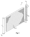
- a heat exchanger 10 as shown on Figure 1 , comprises a first tubular tank 12 extending along a longitudinal axis Al and a second tubular tank 14 that is parallel to the first tank 12.
- the first tank 12 is provided with a fluid inlet (not represented).
- the second tank 14 is provided with a fluid outlet (not represented).
- the tanks 12, 14, are in fluid connection as being transversally interconnected by a plurality of flat tubes 16 extending along a transversal axis A2. Between any two flat tubes 16 are placed cooling fins 18.
- FIGS 2 to 9 illustrate the key steps of the process to manufacture the heat exchanger 10.
- the individual components are initially manufactured and then, certain components are provided with brazing clad. Finally, the heat exchanger is assembled and brazed in a furnace.
- the initial step - Figure 2 - is to provide a rectangular flat metal sheet 20 with length L that is the length of the tank 12, 14, extending along the longitudinal axis A1, and width W that is the circumference of the tank 12, 14.
- the metal sheet 20 has a first longitudinal edge 22 and an opposite second longitudinal edge 24. Both longitudinal edges 22, 24, are provided with a plurality of notches 26. Each notch 26 is perpendicular to the longitudinal edges 22, 24. The notches 26 are aligned and opposed by pair.
- the metal sheet 20 is further provided with a pair of elongated notches 28 and with an opening 30. As shown on Figure 2 , said elongated notches 28 are lengthier than the other notches 26 and the opening 30 is operated between the two elongated notches 28.
- the notches 26, 28, can be made prior, or after, cutting the metal sheet 20 to the L x W dimensions.
- the notches 26, 28, and the opening 30 themselves can be punched or milled or operated with any process.
- the metal sheet 20 is represented symmetrical and the notches 26, 28, are represented having equal lengths.
- lengthier on one side or alternatively lengthier/shorter is also possible.
- the notches 26, 28, can be on one side only of the flat metal sheet 20.
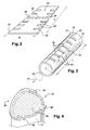
- the following stage - Figure 3 - consists in forming the tubular tanks 12, 14, by rolling the metal sheet 20 so the two longitudinal edges 22 and 24 join each other.
- the metal sheet 20 can be stamped instead of being rolled.
- the notches 26, aligned and opposed by pair prior to rolling, now face each other, forming a plurality of closed slots 32.
- the elongated notches 28 now form an elongated slot 34.
- the two longitudinal edges 22 and 24 are in contact after rolling, forming an edges-joining-line 36 that is interrupted by each slot 32, 34, and that is extending in sections 38 between each two consecutive slots 32, 34.
- the separators 40 are made.
- the separator 40 is a flat piece of metal comprising a central body 44, from which extends a tab 46 and from which split two lateral arms 48 and 50.
- the body 44 has the shape and dimensions of the internal cross section of the tanks 12, 14.
- the lateral arms 48, 50 are parallel to the body 44, forming a pair of indentation 52 and 54 between each arm 48, 50, and the body 44.
- the separators 40 are provided with brazing clad 42 so they can be brazed inside the tanks 12, 14.
- the following stage of the process consists in inserting the separator 40, provided with brazing clad 42, in the elongated slot 34.
- the separator 40 inserted in the elongated slot 34 closes the section of the tubular tank 12, 14.
- the tab 46 is engaged in the opening 30.
- the arms 48 and 50 stay outside the tubular tank 12, 14, and the wall of the tubular tank, which is the thickness of the metal sheet 20, is engaging itself in the indentations 52 and 54.
- said elongated slot 34 must comprise the largest width of the tubular tanks 12, 14. This is why the elongated notches 28 may be lengthier than the other notches 26.
- the brazing step of the process can be prepared.
- brazing clad 42 is provided on the flat tubes 16, as are already the separators 40.
- the tanks 12, 14, and the cooling fins 18 remain free of brazing clad 42.
- the tubular tanks 12, 14, are positioned parallel to each other, the slots 32, 34, facing each other. They are equipped, as previously described by separators 40. As presented on Figure 6 , the tanks 12, 14, may be equipped with more than one separator 40.
- the flat tubes 16 are presented between the tanks 12, 14, and engaged in the slots 32 - Figure 7 . Between any two flat tubes 16 are placed the cooling fins 18.
- brazing clad 42 it is known that too much brazing clad 42 in the brazing joint between two parts generates erosion during brazing, reducing the wall thickness of the brazed parts. It is important that the quantity of brazing clad 42 is limited to the necessary minimum. In this aim, one object of the present invention is to manufacture the heat exchanger 10 in using less clad 42 as in the prior art.
- the tubular tanks 12, 14, and the cooling fins 18 are consequently free of brazing clad while the flat tubes 16 and the separators 40 are provided with brazing clad 42.
- the final stage of manufacturing - Figure 8 and Figure 9 - consists in the brazing operation of the assembly. This is usually done by placing the assembly in a furnace that is heated to the appropriate temperature. In the furnace, the brazing clad 42 which is on the tubes 16 and on the separator 40 melts and flows to all intersections. It flows around the slots 32, brazing the tubes 16 with the tanks 12, 14. It flows along the sections 38 of the edges-joining-line 36, brazing the tubular tanks 12, 14. It flows around the edges of the separator 40 brazing said separator 40 in position in the tanks 12, 14. The sections 38 of the edges-joining-line 36 are consequently exclusively brazed by the brazing clad 42 that is provided on the tubes 16.
- the quantity of brazing clad 42 is preferably, as described above, exclusively provided on the tubes 16.
- the brazing clad 42 can be split between the tubes 16 and the tanks 12, 14.
Abstract
- providing a rectangular metal sheet having notches on one edge, the notches being in the same number as the number of tubes to be connected to the tank,
- forming the metal sheet in a tubular shape until joining the longitudinal edges and closing the notches, forming slots, and creating an edges-joining-line that is discontinued as being interrupted by the slots,
- providing the at least one tube with brazing clad on at least one end of the tube,
- engaging the end of the tube that is provided with brazing clad into the slot formed in the tubular tank,
- brazing the assembly.
Description
- The present invention relates to a process to manufacture a brazed heat exchanger as well as to a brazed heat exchanger.
- Brazed heat exchangers exist since years. They usually comprise a pair of parallel tubular tanks transversally interconnected by a plurality of flat tubes, cooling fins being brazed between the flat tubes. A hot fluid entering via an inlet operated in a tubular tank flows through the transversal tubes, where it cools down, gets in the opposite tank, from where it exits via an outlet.
- Furthermore, to increase the cooling efficiency of the heat exchanger, separators may split the tanks in a plurality of sectors. The hot fluid entering into the first sector of the first tank flows through a first set of tubes in fluid connection with said first sector. The fluid gets to the second tank and flows back to the first tank through a second set of tubes in fluid connection with a second sector of the first tank. The fluid is directed back and forth between the tanks thanks to a plurality of internal separators.
- To manufacture heat exchangers of the above type, a typical process is to manufacture and form the individual components: tanks, tubes, fins, separators..., then to provide the components with brazing clad, to assemble the components and finally to braze the assembly in a furnace.
- The tubular tanks are complex part to manufacture. The cost efficient technology of rolling versus extruding has been developed. Starting from a flat rectangular sheet of metal, slots are punched in the central part of the metal sheet, away from the edges and then the flat metal sheet is rolled. The slots dedicated to the separators are larger than the slots for the flat tubes. Indeed, a separator inserted through its slot, must occupy the entire internal section of the tubular tank. Thus, the slots for the separators are open through, at least, the largest width of the tank, measured transversally to the direction of insertion of the separator.
- The rolling process generates a joining-line. The brazing clad has to be on both the tubular tanks and on the flat tubes in order to braze the tank in a rolled position as well as to braze the flat tubes to the tubular tank.
- In
US 2009/0173478 A1 , Beamer discloses a heat exchanger of the prior art. The joining-line of the rolled tank is continued and diametrally opposed to the slots where are inserted the flat tubes. The brazing of this heat exchanger requires the tank and the transversal tubes to be provided with brazing clad. - In a pursuit for optimization of quality and cost, the current known process presents several issues.
- The tubular tank, the flat tubes and the separators are all provided with brazing clad which requires multiple operations and adds cost.
- The slot for a separator being very large, the separator itself is not very well positioned before brazing.
- This design results in increased time to manufacture and assemble and an increased overall cost. It is important to propose a process and related product solving the mentioned problems in further simplification of the process and reduction of utilized material.
- Accordingly, it is an object of the present invention to propose a process to manufacture a heat exchange, the process using less brazing clad as in the prior art.
- In carrying out the above object and other objects, features, and advantages, the present invention provides a process to manufacture a heat exchanger according to the preamble of claim 1.
- Specifically, the present invention is a process to manufacture a brazed heat exchanger comprising a tubular tank and at least one tube inserted in a corresponding slot operated in the tubular tank, the at least one tube being in fluid communication with the tubular tank. The process is comprises the steps of
- providing a rectangular metal sheet having longitudinal edges of length equal to the length of the tubular tank, and transversal widths equal to the circumference of the tubular tank. The metal sheet is provided with notches operated on one longitudinal edge of the metal sheet, the notches are in the same number as the number of tubes to be connected to the tank,
- forming the metal sheet in a tubular shape so longitudinal edges join and the notches close thus slots are formed, and an edges-joining-line is created. This edges-joining-line is discontinued as being interrupted by the slots.
- providing the at least one tube with brazing clad on at least one end of the tube,
- engaging the end of the tube that is provided with brazing clad into the slot formed in the tubular tank, and finally,
- brazing the assembly.
- Advantageously, in these steps,
- the brazing clad can exclusively be provided on the tube, and
- the metal sheet be consequently free of brazing clad.
- The tube and the tank as well as the edges-joining-line are then brazed exclusively with the brazing clad flowing from the tube.
- Also, the rectangular metal sheet can be provided with notches operated on both longitudinal edges.
- More particularly, the rectangular metal sheet can be provided with notches oppositely aligned by pair, so when the metal sheet is put in a tubular shape each notch faces its opposite notch forming a closed slot.
- Furthermore, the notches oppositely aligned by pair, can have equal length, so when the metal sheet is rolled the edges-joining-line is discontinued as interrupted by the middle of each slot.
- The process comprises the additional step of:
- providing a metallic flat separator having a main body with substantially the same dimensions as the internal section of the tubular tank and a tab extending from said body,
- providing an elongated slot for the separator,
- forming in the metal sheet an opening so, after the forming step of the process, said opening is substantially diametrally positioned from said elongated slot,
- inserting the separator through said elongated slot and engaging the tab in the opening.
- The elongated slot dedicated to the insertion of the separator enables the insertion of said separator, the body of which fully occupying the internal section of the metal sheet in a tubular shape.
- Additionally, the separator is provided with at least one lateral arm extending from the body and following the body so an indentation is formed between the body and the lateral arm and, when the body is inserted in the elongated slot, the wall of the tubular tank engages in the indentation, the lateral arm staying outside the tubular tank.
- Advantageously, the separator can be provided with two lateral arms symmetrically extending from the body and following said body so two indentations are formed between the body and the lateral arms. Consequently, when the body is inserted in the elongated slot, the wall of the tubular tank engages in the indentations, the two lateral arms staying outside the tank. Advantageously, prior to brazing, the lateral arms maintain the metal sheet in the tubular shape and secure the positioning of the separator in the tubular tank.
- To braze the assembly, brazing clad is provided on the separator and, when brazing the assembly in a furnace, the brazing clad on the separator flows from the separator to the intersection of the tank and the separator to braze the separator in the tubular tank.
- More generally, the process of the present invention is applicable when two parallel tubular tanks are provided, both being free of brazing clad. The separators are inserted in the tubular tanks, the separators being provided with brazing clad. After, the tubular tanks are interconnected with a plurality of tubes provided with brazing clad. Also, cooling fins are placed between the tubes, the cooling fins being free of brazing clad. Finally, the assembly is brazed so, the brazing clad present on the separator melts and flows between the separator and the internal section of the tubular tank, brazing the separators in the tank and, the brazing clad present on the ends of the tubes flows around the slots between the tubes and the tanks as well as along the edges-joining-line extending between two consecutive slots and, the brazing clad present on the tubes brazes the cooling fins with the tubes.
- The step of the process by which the metal sheet is formed in a tubular shape is rolling or stamping.The present invention also relates to a brazed heat exchanger assembly comprising at least one tubular tank, at least one tube in fluid connection with said tank, the tubular tank having a discontinued edges-joining-line interrupted at the connection with the at least one tube.
- The present invention also relates to a brazed heat exchanger assembly having two tubular tanks, and a plurality of tubes interconnecting said tubular tanks, and where at least one of the tubular tanks has a discontinued edges-joining-line interrupted at the connection with the tubes.
- Also, the brazed heat exchanger assembly can comprise a separator inserted in a slot of a tubular tank. The separator is provided with at least one arm extending along the outside surface of the tubular tank for maintaining, prior to brazing, the separator in place as well as the tubular tank in a tubular shape.
- The present invention is now described by way of example with reference to the accompanying drawings in which:
-
Figure 1 is a general view of a brazed heat exchanger manufactured according to the process of the invention. -
Figure 2 is an isometric view of a flat metal sheet provided with notches, aligned by pair, on each longitudinal edge. -
Figure 3 is an isometric view of the metal sheet ofFigure 2 after rolling. -
Figure 4 is a transversal section of the rolled metal sheet ofFigure 3 through an elongated slot where a separator has been inserted. -
Figure 5 is an isometric view of the rolled metal sheet ofFigure 3 provided with a separator ofFigure 4 and end caps. -
Figure 6 is an isometric view of the heat exchanger where all components are ready to be put place. -
Figure 7 is a transversal section of the heat exchanger, through a flat tube interconnecting two tubular tanks. -
Figure 8 is an isometric view detailing the assembly of a tank with tubes and a separator before the brazing stage of the process. -
Figure 9 is the isometric view ofFigure 8 after the brazing step of the process. - In the following description, similar elements could be designated with the same reference numbers.
- A
heat exchanger 10, as shown onFigure 1 , comprises afirst tubular tank 12 extending along a longitudinal axis Al and asecond tubular tank 14 that is parallel to thefirst tank 12. Thefirst tank 12 is provided with a fluid inlet (not represented). Thesecond tank 14 is provided with a fluid outlet (not represented). Thetanks flat tubes 16 extending along a transversal axis A2. Between any twoflat tubes 16 are placed coolingfins 18. -
Figures 2 to 9 illustrate the key steps of the process to manufacture theheat exchanger 10. The individual components are initially manufactured and then, certain components are provided with brazing clad. Finally, the heat exchanger is assembled and brazed in a furnace. - The initial step -
Figure 2 - is to provide a rectangular flat metal sheet 20 with length L that is the length of thetank tank longitudinal edge 22 and an opposite secondlongitudinal edge 24. Bothlongitudinal edges notches 26. Eachnotch 26 is perpendicular to thelongitudinal edges notches 26 are aligned and opposed by pair. - In order to be able to place a
separator 40 in thetubular tank elongated notches 28 and with anopening 30. As shown onFigure 2 , saidelongated notches 28 are lengthier than theother notches 26 and theopening 30 is operated between the twoelongated notches 28. - Alternative processes can be implemented to get to this initial stage of the invention. The
notches notches opening 30 themselves can be punched or milled or operated with any process. - Furthermore, the metal sheet 20 is represented symmetrical and the
notches notches - The following stage -
Figure 3 - consists in forming thetubular tanks longitudinal edges Figure 3 , thenotches 26, aligned and opposed by pair prior to rolling, now face each other, forming a plurality ofclosed slots 32. Theelongated notches 28 now form anelongated slot 34. The twolongitudinal edges line 36 that is interrupted by eachslot sections 38 between each twoconsecutive slots - Alternatively, in the case of
notches longitudinal edge 22 only, the rolling stage of the process brings the open end of thenotches longitudinal edge 24 thus forming theslots - In a parallel step as preparing the
tubular tanks separators 40 are made. As shown onFigure 4 and onFigure 6 , theseparator 40 is a flat piece of metal comprising acentral body 44, from which extends atab 46 and from which split twolateral arms body 44 has the shape and dimensions of the internal cross section of thetanks lateral arms body 44, forming a pair ofindentation arm body 44. - In preparation to the brazing step of the process, the
separators 40 are provided with brazing clad 42 so they can be brazed inside thetanks - The following stage of the process, illustrated by
Figure 4 , consists in inserting theseparator 40, provided with brazing clad 42, in theelongated slot 34. As shown onFigure 4 , theseparator 40 inserted in theelongated slot 34 closes the section of thetubular tank tab 46 is engaged in theopening 30. Thearms tubular tank indentations separator 40 through theelongated slot 34, saidelongated slot 34 must comprise the largest width of thetubular tanks elongated notches 28 may be lengthier than theother notches 26. Thanks to thelateral arms tubular tanks tanks Figure 4 . In addition to theseparator 40, twoend caps tanks 12, 14 -Figure 5 . - Once the
tanks separators 40 andend caps 58, 60, thetubes 16 and the coolingfins 18 are available, the brazing step of the process can be prepared. - At first, brazing clad 42 is provided on the
flat tubes 16, as are already theseparators 40. Thetanks fins 18 remain free of brazing clad 42. - At second, the components are assembled as illustrated on
Figure 6 and onFigure 7 . Thetubular tanks slots separators 40. As presented onFigure 6 , thetanks separator 40. Theflat tubes 16 are presented between thetanks Figure 7 . Between any twoflat tubes 16 are placed the coolingfins 18. - It is known that too much brazing clad 42 in the brazing joint between two parts generates erosion during brazing, reducing the wall thickness of the brazed parts. It is important that the quantity of brazing clad 42 is limited to the necessary minimum. In this aim, one object of the present invention is to manufacture the
heat exchanger 10 in using less clad 42 as in the prior art. Thetubular tanks fins 18 are consequently free of brazing clad while theflat tubes 16 and theseparators 40 are provided with brazing clad 42. - The final stage of manufacturing -
Figure 8 and Figure 9 - consists in the brazing operation of the assembly. This is usually done by placing the assembly in a furnace that is heated to the appropriate temperature. In the furnace, the brazing clad 42 which is on thetubes 16 and on theseparator 40 melts and flows to all intersections. It flows around theslots 32, brazing thetubes 16 with thetanks sections 38 of the edges-joining-line 36, brazing thetubular tanks separator 40 brazing saidseparator 40 in position in thetanks sections 38 of the edges-joining-line 36 are consequently exclusively brazed by the brazing clad 42 that is provided on thetubes 16. - To achieve the objective of saving brazing clad 42 over the process of the prior art, the quantity of brazing clad 42 is preferably, as described above, exclusively provided on the tubes 16.Alternatively, the brazing clad 42 can be split between the
tubes 16 and thetanks
Claims (15)
- Process to manufacture a brazed heat exchanger (10) comprising a tubular tank (12) and at least one tube (16) inserted in a corresponding slot (32) operated in the tubular tank (12), the at least one tube (16) being in fluid communication with the tubular tank (12), the process being characterized in that it comprises the steps of:- providing a rectangular metal sheet (20) having longitudinal edges (22, 24) of length (L) equal to the length of the tubular tank (12), and transversal widths (W) equal to the circumference of the tubular tank (12), the metal sheet (20) being provided with notches (26) operated on one longitudinal edge (22, 24) of the metal sheet (20), the notches (26) being in the same number as the number of tubes (16) to be connected to the tank (12),- forming the metal sheet (20) in a tubular shape so the longitudinal edges (22, 24) join and the notches (26) close thus forming slots (32), and creating an edges-joining-line (36) that is discontinued as being interrupted by the slots (32),- providing the at least one tube (16) with brazing clad (42) on at least one end of the tube (16),- engaging the end of the tube (16) that is provided with brazing clad (42) into the slot (32) formed in the tubular tank (12),- brazing the assembly.
- Process as set forth in claim 1 wherein- the brazing clad (42) is being exclusively provided on the tube (16),- the metal sheet (20) is being free of brazing clad (42) so, the tube (16) and the tank (12) as well as the edges-joining-line (36) are being brazed exclusively with the brazing clad (42) flowing from the tube (16).
- Process as set forth in any of the preceding claims wherein- the rectangular metal sheet (20) is being provided with notches (26) operated on both longitudinal edges (22, 24).
- Process as set forth in claim 3 wherein- the rectangular metal sheet (20) is being provided with notches (26) oppositely aligned by pair,- the metal sheet (20) is being put in a tubular shape so each notch (26) faces its opposite notch thus forming a closed slot (32).
- Process as set forth in claim 4 wherein- the notches (26), oppositely aligned by pair, are having equal length, so when the metal sheet (20) is being formed in a tubular shape the edges-joining-line (36) is being discontinued as being interrupted by the middle of each slot (32).
- Process as set in any of the preceding claim comprising the additional step of:- providing a metallic flat separator (40) having a main body (44) with substantially the same dimensions as the internal section of the tubular tank (12, 14) and a tab (46) extending from said body (44),- providing an elongated slot (34) for the separator (40),- forming in the metal sheet (20) an opening (30) so, after the forming step of the process, said opening (30) is substantially diametrally positioned from said elongated slot (34),- inserting the separator (40) through said elongated slot (34) and engaging the tab (46) in the opening (30).
- Process as set in claim 6, wherein the elongated slot (34) dedicated to the insertion of the separator (40) enables the insertion of said separator (40), the body (44) of which fully occupying the internal section of the metal sheet in a tubular shape (20).
- Process as set in any of the claim 6 or 7 wherein- the separator (40) is being provided with at least one lateral arm (48) extending from the body(44) and following the body (44) so an indentation (52) is being formed between the body (44) and the lateral arm (48) and wherein,- the body (44) of the separator (40) is being inserted in the elongated slot (34), engaging the wall of the tubular tank (12, 14) in the indentation (52), the lateral arm (48) staying outside the tubular tank (12, 14).
- Process as set in any of the claim 6 to 8 wherein:- the separator (40) is being provided with two lateral arms (48, 50) symmetrically extending from the body (44) and following said body (44) so two indentations (52, 54) are being formed between the body (44) and the lateral arms (48, 50), and wherein- the body (44) is being inserted in the elongated slot (34), the wall of the tubular tank (12, 14) engaging in said indentations (52, 54), the two lateral arms (48, 50) staying outside the tank (12, 14) thus maintaining the metal sheet (20) in the tubular shape prior to brazing and further securing the positioning of the separator (40) in the tubular tank (12, 14).
- Process as set in any of the claim 6 to 9 further comprising the step of:- providing brazing clad (42) on the separator (40),- brazing the assembly, the brazing clad (42) on the separator (40) flowing from the separator (40) to the intersection of the tank (12, 14) and the separator (40) to braze the separator (40) in the tubular tank (12, 14).
- Process as set in any of the claim 6 to 10 wherein- two parallel tubular tanks (12,14) are being provided, both being free of brazing clad,- the separators (40) are being inserted in the tubular tanks (12, 14) the separators (40) being provided with brazing clad (42),- the tubular tanks (12, 14) are being interconnected with a plurality of tubes (16), the tubes (16) being provided with brazing clad (42),- cooling fins (18) are being placed between the tubes (16), the cooling fins (18) being free of brazing clad,- the assembly is being brazed so- the brazing clad (42) present on the separator (40) melts and flows between the separator (40) and the internal section of the tubular tank (12, 14), brazing the separators (40) in the tank (12, 14) and,- the brazing clad (42) present on the ends of the tubes (16) flows around the slots (32) between the tubes (16) and the tanks (12, 14) as well as along the edges-joining-line (36) extending between two consecutive slots (32) and,- the brazing clad (42) present on the tubes (16) brazes the cooling fins (18) with the tubes (16).
- Process as set in any of the preceding claim wherein the step of forming the metal sheet (20) in a tubular shape is rolling or stamping.
- A brazed heat exchanger assembly (10) comprising- at least one tubular tank (12, 14),- at least one tube (16) in fluid connection with said tank (12, 14),characterized in that
said tubular tank (12, 14) has a discontinued edges-joining-line (36) interrupted at the connection with the at least one tube (16). - A brazed heat exchanger assembly (10) as set in claim 13 comprising- two tubular tanks (12, 14),- a plurality of tubes (16) interconnecting said tubular tanks (12, 14),characterized in that
at least one of the tubular tanks (12, 14) has a discontinued edges-joining-line (36) interrupted at the connection with the tubes (16). - A brazed heat exchanger assembly (10) as set in any of the claim 13 or 14 characterized in that it further comprises
a separator (40) inserted in a slot (34) of the tubular tank (12, 14), said separator (40) being provided with at least one arm (48, 50) extending along the outside surface of the tubular tank (12, 14) for maintaining, prior to brazing, the separator in place as well as the tubular tank (12, 14) in a tubular shape.
Priority Applications (1)
| Application Number | Priority Date | Filing Date | Title |
|---|---|---|---|
| EP10169012.1A EP2405224B1 (en) | 2010-07-09 | 2010-07-09 | Process for manufacturing a brazed heat exchanger |
Applications Claiming Priority (1)
| Application Number | Priority Date | Filing Date | Title |
|---|---|---|---|
| EP10169012.1A EP2405224B1 (en) | 2010-07-09 | 2010-07-09 | Process for manufacturing a brazed heat exchanger |
Publications (2)
| Publication Number | Publication Date |
|---|---|
| EP2405224A1 true EP2405224A1 (en) | 2012-01-11 |
| EP2405224B1 EP2405224B1 (en) | 2018-09-05 |
Family
ID=43349064
Family Applications (1)
| Application Number | Title | Priority Date | Filing Date |
|---|---|---|---|
| EP10169012.1A Not-in-force EP2405224B1 (en) | 2010-07-09 | 2010-07-09 | Process for manufacturing a brazed heat exchanger |
Country Status (1)
| Country | Link |
|---|---|
| EP (1) | EP2405224B1 (en) |
Cited By (2)
| Publication number | Priority date | Publication date | Assignee | Title |
|---|---|---|---|---|
| DE102014011638A1 (en) * | 2014-08-06 | 2016-02-11 | Modine Manufacturing Co. | Soldered gas cooler |
| US20210252649A1 (en) * | 2020-02-13 | 2021-08-19 | Consolidated Edison Company Of New York, Inc. | Boiler tube panel installation device and method of aligning |
Citations (8)
| Publication number | Priority date | Publication date | Assignee | Title |
|---|---|---|---|---|
| JPH03260596A (en) * | 1990-03-07 | 1991-11-20 | Sanden Corp | Preparation of heat exchanger |
| JPH03260595A (en) * | 1990-03-07 | 1991-11-20 | Sanden Corp | Preparation of heat exchanger |
| US5125454A (en) * | 1991-08-27 | 1992-06-30 | Thermal Components, Inc. | Manifold assembly for a parallel flow heat exchanger |
| US5207738A (en) * | 1992-08-28 | 1993-05-04 | Valeo | Heat exchanger manifold assembly |
| US5214847A (en) * | 1990-03-07 | 1993-06-01 | Sanden Corporation | Method for manufacturing a heat exchanger |
| US6053243A (en) * | 1996-07-17 | 2000-04-25 | Zexel Corporation | Header pipe for heat exchanger and manufacturing apparatus and manufacturing method thereof |
| EP1275926A2 (en) * | 2001-06-26 | 2003-01-15 | Calsonic Kansei Corporation | Tank of heat exchanger and method of producing same |
| US20090173478A1 (en) | 2008-01-09 | 2009-07-09 | Delphi Technologies, Inc. | Frost tolerant fins |
-
2010
- 2010-07-09 EP EP10169012.1A patent/EP2405224B1/en not_active Not-in-force
Patent Citations (8)
| Publication number | Priority date | Publication date | Assignee | Title |
|---|---|---|---|---|
| JPH03260596A (en) * | 1990-03-07 | 1991-11-20 | Sanden Corp | Preparation of heat exchanger |
| JPH03260595A (en) * | 1990-03-07 | 1991-11-20 | Sanden Corp | Preparation of heat exchanger |
| US5214847A (en) * | 1990-03-07 | 1993-06-01 | Sanden Corporation | Method for manufacturing a heat exchanger |
| US5125454A (en) * | 1991-08-27 | 1992-06-30 | Thermal Components, Inc. | Manifold assembly for a parallel flow heat exchanger |
| US5207738A (en) * | 1992-08-28 | 1993-05-04 | Valeo | Heat exchanger manifold assembly |
| US6053243A (en) * | 1996-07-17 | 2000-04-25 | Zexel Corporation | Header pipe for heat exchanger and manufacturing apparatus and manufacturing method thereof |
| EP1275926A2 (en) * | 2001-06-26 | 2003-01-15 | Calsonic Kansei Corporation | Tank of heat exchanger and method of producing same |
| US20090173478A1 (en) | 2008-01-09 | 2009-07-09 | Delphi Technologies, Inc. | Frost tolerant fins |
Cited By (3)
| Publication number | Priority date | Publication date | Assignee | Title |
|---|---|---|---|---|
| DE102014011638A1 (en) * | 2014-08-06 | 2016-02-11 | Modine Manufacturing Co. | Soldered gas cooler |
| US20210252649A1 (en) * | 2020-02-13 | 2021-08-19 | Consolidated Edison Company Of New York, Inc. | Boiler tube panel installation device and method of aligning |
| US11638974B2 (en) * | 2020-02-13 | 2023-05-02 | Consolidated Edison Company Of New York, Inc. | Boiler tube panel installation device and method of aligning |
Also Published As
| Publication number | Publication date |
|---|---|
| EP2405224B1 (en) | 2018-09-05 |
Similar Documents
| Publication | Publication Date | Title |
|---|---|---|
| EP1195573B2 (en) | Heat exchanger and method of making the same | |
| CA2508684C (en) | Stacking-type, multi-flow, heat exchangers and methods for manufacturing such heat exchangers | |
| JP4099513B2 (en) | Metal plate for flat tube manufacturing, flat tube and flat tube manufacturing method | |
| JP2007303813A (en) | Self-braking radiator side plate | |
| EP2871434A1 (en) | Heat exchanger and method of manufacturing the same | |
| JPH05172488A (en) | Partition plate assembling structure of header pipe for heat exchanger and assembling method therefor | |
| WO2005116562A1 (en) | Tube feature for limiting insertion depth into header slot | |
| JP2007125590A (en) | Heat exchanger and method for manufacturing heat exchanger | |
| EP2405224B1 (en) | Process for manufacturing a brazed heat exchanger | |
| US20050279485A1 (en) | Stacking-type, multi-flow, heat exchangers and methods for manufacturing such heat exchangers | |
| EP1850076A2 (en) | Refrigerant condenser equipped with receiver | |
| JP2016097434A (en) | Tube for heat exchanger and its manufacturing method | |
| JPH1047888A (en) | Heat exchanger | |
| JP2014105951A (en) | Heat exchanger | |
| KR20070108078A (en) | Transition assembly and method of connecting to a heat exchanger | |
| JP4300499B2 (en) | Fin coil type heat exchanger and manufacturing method thereof | |
| JP2017009191A (en) | Temporary assembly means of header plate and core of heat exchanger | |
| EP3767217B1 (en) | Tube for a heat exchanger | |
| EP1744116A2 (en) | Heat exchanger | |
| KR19980070184A (en) | heat transmitter | |
| JP2005114199A (en) | Header for heat exchanger and manufacturing method thereof | |
| JP2010101516A (en) | Inner fin for heat exchanger | |
| GB2320957A (en) | Heat exchanger and header | |
| JP2017089927A (en) | Aluminum heat exchanger | |
| JP4371417B2 (en) | Manufacturing method of heat exchanger |
Legal Events
| Date | Code | Title | Description |
|---|---|---|---|
| AK | Designated contracting states |
Kind code of ref document: A1 Designated state(s): AL AT BE BG CH CY CZ DE DK EE ES FI FR GB GR HR HU IE IS IT LI LT LU LV MC MK MT NL NO PL PT RO SE SI SK SM TR |
|
| AX | Request for extension of the european patent |
Extension state: BA ME RS |
|
| PUAI | Public reference made under article 153(3) epc to a published international application that has entered the european phase |
Free format text: ORIGINAL CODE: 0009012 |
|
| 17P | Request for examination filed |
Effective date: 20120711 |
|
| RAP1 | Party data changed (applicant data changed or rights of an application transferred) |
Owner name: MAHLE INTERNATIONAL GMBH |
|
| GRAP | Despatch of communication of intention to grant a patent |
Free format text: ORIGINAL CODE: EPIDOSNIGR1 |
|
| STAA | Information on the status of an ep patent application or granted ep patent |
Free format text: STATUS: GRANT OF PATENT IS INTENDED |
|
| RIC1 | Information provided on ipc code assigned before grant |
Ipc: F28F 9/02 20060101AFI20180208BHEP Ipc: B21D 53/08 20060101ALI20180208BHEP |
|
| INTG | Intention to grant announced |
Effective date: 20180313 |
|
| GRAS | Grant fee paid |
Free format text: ORIGINAL CODE: EPIDOSNIGR3 |
|
| GRAA | (expected) grant |
Free format text: ORIGINAL CODE: 0009210 |
|
| STAA | Information on the status of an ep patent application or granted ep patent |
Free format text: STATUS: THE PATENT HAS BEEN GRANTED |
|
| AK | Designated contracting states |
Kind code of ref document: B1 Designated state(s): AL AT BE BG CH CY CZ DE DK EE ES FI FR GB GR HR HU IE IS IT LI LT LU LV MC MK MT NL NO PL PT RO SE SI SK SM TR |
|
| REG | Reference to a national code |
Ref country code: GB Ref legal event code: FG4D |
|
| REG | Reference to a national code |
Ref country code: CH Ref legal event code: EP |
|
| REG | Reference to a national code |
Ref country code: AT Ref legal event code: REF Ref document number: 1038324 Country of ref document: AT Kind code of ref document: T Effective date: 20180915 |
|
| REG | Reference to a national code |
Ref country code: IE Ref legal event code: FG4D |
|
| REG | Reference to a national code |
Ref country code: DE Ref legal event code: R096 Ref document number: 602010053263 Country of ref document: DE |
|
| REG | Reference to a national code |
Ref country code: NL Ref legal event code: MP Effective date: 20180905 |
|
| REG | Reference to a national code |
Ref country code: LT Ref legal event code: MG4D |
|
| PG25 | Lapsed in a contracting state [announced via postgrant information from national office to epo] |
Ref country code: GR Free format text: LAPSE BECAUSE OF FAILURE TO SUBMIT A TRANSLATION OF THE DESCRIPTION OR TO PAY THE FEE WITHIN THE PRESCRIBED TIME-LIMIT Effective date: 20181206 Ref country code: NO Free format text: LAPSE BECAUSE OF FAILURE TO SUBMIT A TRANSLATION OF THE DESCRIPTION OR TO PAY THE FEE WITHIN THE PRESCRIBED TIME-LIMIT Effective date: 20181205 Ref country code: LT Free format text: LAPSE BECAUSE OF FAILURE TO SUBMIT A TRANSLATION OF THE DESCRIPTION OR TO PAY THE FEE WITHIN THE PRESCRIBED TIME-LIMIT Effective date: 20180905 Ref country code: BG Free format text: LAPSE BECAUSE OF FAILURE TO SUBMIT A TRANSLATION OF THE DESCRIPTION OR TO PAY THE FEE WITHIN THE PRESCRIBED TIME-LIMIT Effective date: 20181205 Ref country code: FI Free format text: LAPSE BECAUSE OF FAILURE TO SUBMIT A TRANSLATION OF THE DESCRIPTION OR TO PAY THE FEE WITHIN THE PRESCRIBED TIME-LIMIT Effective date: 20180905 Ref country code: SE Free format text: LAPSE BECAUSE OF FAILURE TO SUBMIT A TRANSLATION OF THE DESCRIPTION OR TO PAY THE FEE WITHIN THE PRESCRIBED TIME-LIMIT Effective date: 20180905 |
|
| REG | Reference to a national code |
Ref country code: AT Ref legal event code: MK05 Ref document number: 1038324 Country of ref document: AT Kind code of ref document: T Effective date: 20180905 |
|
| PG25 | Lapsed in a contracting state [announced via postgrant information from national office to epo] |
Ref country code: ES Free format text: LAPSE BECAUSE OF FAILURE TO SUBMIT A TRANSLATION OF THE DESCRIPTION OR TO PAY THE FEE WITHIN THE PRESCRIBED TIME-LIMIT Effective date: 20180905 Ref country code: LV Free format text: LAPSE BECAUSE OF FAILURE TO SUBMIT A TRANSLATION OF THE DESCRIPTION OR TO PAY THE FEE WITHIN THE PRESCRIBED TIME-LIMIT Effective date: 20180905 Ref country code: AL Free format text: LAPSE BECAUSE OF FAILURE TO SUBMIT A TRANSLATION OF THE DESCRIPTION OR TO PAY THE FEE WITHIN THE PRESCRIBED TIME-LIMIT Effective date: 20180905 Ref country code: HR Free format text: LAPSE BECAUSE OF FAILURE TO SUBMIT A TRANSLATION OF THE DESCRIPTION OR TO PAY THE FEE WITHIN THE PRESCRIBED TIME-LIMIT Effective date: 20180905 |
|
| PG25 | Lapsed in a contracting state [announced via postgrant information from national office to epo] |
Ref country code: EE Free format text: LAPSE BECAUSE OF FAILURE TO SUBMIT A TRANSLATION OF THE DESCRIPTION OR TO PAY THE FEE WITHIN THE PRESCRIBED TIME-LIMIT Effective date: 20180905 Ref country code: PL Free format text: LAPSE BECAUSE OF FAILURE TO SUBMIT A TRANSLATION OF THE DESCRIPTION OR TO PAY THE FEE WITHIN THE PRESCRIBED TIME-LIMIT Effective date: 20180905 Ref country code: IT Free format text: LAPSE BECAUSE OF FAILURE TO SUBMIT A TRANSLATION OF THE DESCRIPTION OR TO PAY THE FEE WITHIN THE PRESCRIBED TIME-LIMIT Effective date: 20180905 Ref country code: AT Free format text: LAPSE BECAUSE OF FAILURE TO SUBMIT A TRANSLATION OF THE DESCRIPTION OR TO PAY THE FEE WITHIN THE PRESCRIBED TIME-LIMIT Effective date: 20180905 Ref country code: IS Free format text: LAPSE BECAUSE OF FAILURE TO SUBMIT A TRANSLATION OF THE DESCRIPTION OR TO PAY THE FEE WITHIN THE PRESCRIBED TIME-LIMIT Effective date: 20190105 Ref country code: CZ Free format text: LAPSE BECAUSE OF FAILURE TO SUBMIT A TRANSLATION OF THE DESCRIPTION OR TO PAY THE FEE WITHIN THE PRESCRIBED TIME-LIMIT Effective date: 20180905 Ref country code: NL Free format text: LAPSE BECAUSE OF FAILURE TO SUBMIT A TRANSLATION OF THE DESCRIPTION OR TO PAY THE FEE WITHIN THE PRESCRIBED TIME-LIMIT Effective date: 20180905 Ref country code: RO Free format text: LAPSE BECAUSE OF FAILURE TO SUBMIT A TRANSLATION OF THE DESCRIPTION OR TO PAY THE FEE WITHIN THE PRESCRIBED TIME-LIMIT Effective date: 20180905 |
|
| PG25 | Lapsed in a contracting state [announced via postgrant information from national office to epo] |
Ref country code: SM Free format text: LAPSE BECAUSE OF FAILURE TO SUBMIT A TRANSLATION OF THE DESCRIPTION OR TO PAY THE FEE WITHIN THE PRESCRIBED TIME-LIMIT Effective date: 20180905 Ref country code: PT Free format text: LAPSE BECAUSE OF FAILURE TO SUBMIT A TRANSLATION OF THE DESCRIPTION OR TO PAY THE FEE WITHIN THE PRESCRIBED TIME-LIMIT Effective date: 20190105 Ref country code: SK Free format text: LAPSE BECAUSE OF FAILURE TO SUBMIT A TRANSLATION OF THE DESCRIPTION OR TO PAY THE FEE WITHIN THE PRESCRIBED TIME-LIMIT Effective date: 20180905 |
|
| REG | Reference to a national code |
Ref country code: DE Ref legal event code: R097 Ref document number: 602010053263 Country of ref document: DE |
|
| PLBE | No opposition filed within time limit |
Free format text: ORIGINAL CODE: 0009261 |
|
| STAA | Information on the status of an ep patent application or granted ep patent |
Free format text: STATUS: NO OPPOSITION FILED WITHIN TIME LIMIT |
|
| PG25 | Lapsed in a contracting state [announced via postgrant information from national office to epo] |
Ref country code: DK Free format text: LAPSE BECAUSE OF FAILURE TO SUBMIT A TRANSLATION OF THE DESCRIPTION OR TO PAY THE FEE WITHIN THE PRESCRIBED TIME-LIMIT Effective date: 20180905 |
|
| 26N | No opposition filed |
Effective date: 20190606 |
|
| PG25 | Lapsed in a contracting state [announced via postgrant information from national office to epo] |
Ref country code: SI Free format text: LAPSE BECAUSE OF FAILURE TO SUBMIT A TRANSLATION OF THE DESCRIPTION OR TO PAY THE FEE WITHIN THE PRESCRIBED TIME-LIMIT Effective date: 20180905 |
|
| REG | Reference to a national code |
Ref country code: DE Ref legal event code: R119 Ref document number: 602010053263 Country of ref document: DE |
|
| PG25 | Lapsed in a contracting state [announced via postgrant information from national office to epo] |
Ref country code: MC Free format text: LAPSE BECAUSE OF FAILURE TO SUBMIT A TRANSLATION OF THE DESCRIPTION OR TO PAY THE FEE WITHIN THE PRESCRIBED TIME-LIMIT Effective date: 20180905 |
|
| REG | Reference to a national code |
Ref country code: CH Ref legal event code: PL |
|
| GBPC | Gb: european patent ceased through non-payment of renewal fee |
Effective date: 20190709 |
|
| PG25 | Lapsed in a contracting state [announced via postgrant information from national office to epo] |
Ref country code: TR Free format text: LAPSE BECAUSE OF FAILURE TO SUBMIT A TRANSLATION OF THE DESCRIPTION OR TO PAY THE FEE WITHIN THE PRESCRIBED TIME-LIMIT Effective date: 20180905 |
|
| REG | Reference to a national code |
Ref country code: BE Ref legal event code: MM Effective date: 20190731 |
|
| PG25 | Lapsed in a contracting state [announced via postgrant information from national office to epo] |
Ref country code: GB Free format text: LAPSE BECAUSE OF NON-PAYMENT OF DUE FEES Effective date: 20190709 Ref country code: DE Free format text: LAPSE BECAUSE OF NON-PAYMENT OF DUE FEES Effective date: 20200201 |
|
| PG25 | Lapsed in a contracting state [announced via postgrant information from national office to epo] |
Ref country code: LI Free format text: LAPSE BECAUSE OF NON-PAYMENT OF DUE FEES Effective date: 20190731 Ref country code: LU Free format text: LAPSE BECAUSE OF NON-PAYMENT OF DUE FEES Effective date: 20190709 Ref country code: BE Free format text: LAPSE BECAUSE OF NON-PAYMENT OF DUE FEES Effective date: 20190731 Ref country code: CH Free format text: LAPSE BECAUSE OF NON-PAYMENT OF DUE FEES Effective date: 20190731 |
|
| PG25 | Lapsed in a contracting state [announced via postgrant information from national office to epo] |
Ref country code: FR Free format text: LAPSE BECAUSE OF NON-PAYMENT OF DUE FEES Effective date: 20190731 |
|
| PG25 | Lapsed in a contracting state [announced via postgrant information from national office to epo] |
Ref country code: IE Free format text: LAPSE BECAUSE OF NON-PAYMENT OF DUE FEES Effective date: 20190709 |
|
| PG25 | Lapsed in a contracting state [announced via postgrant information from national office to epo] |
Ref country code: CY Free format text: LAPSE BECAUSE OF FAILURE TO SUBMIT A TRANSLATION OF THE DESCRIPTION OR TO PAY THE FEE WITHIN THE PRESCRIBED TIME-LIMIT Effective date: 20180905 |
|
| PG25 | Lapsed in a contracting state [announced via postgrant information from national office to epo] |
Ref country code: HU Free format text: LAPSE BECAUSE OF FAILURE TO SUBMIT A TRANSLATION OF THE DESCRIPTION OR TO PAY THE FEE WITHIN THE PRESCRIBED TIME-LIMIT; INVALID AB INITIO Effective date: 20100709 Ref country code: MT Free format text: LAPSE BECAUSE OF FAILURE TO SUBMIT A TRANSLATION OF THE DESCRIPTION OR TO PAY THE FEE WITHIN THE PRESCRIBED TIME-LIMIT Effective date: 20180905 |
|
| PG25 | Lapsed in a contracting state [announced via postgrant information from national office to epo] |
Ref country code: MK Free format text: LAPSE BECAUSE OF FAILURE TO SUBMIT A TRANSLATION OF THE DESCRIPTION OR TO PAY THE FEE WITHIN THE PRESCRIBED TIME-LIMIT Effective date: 20180905 |