EP2404855A2 - Yarn winding device - Google Patents
Yarn winding device Download PDFInfo
- Publication number
- EP2404855A2 EP2404855A2 EP11171020A EP11171020A EP2404855A2 EP 2404855 A2 EP2404855 A2 EP 2404855A2 EP 11171020 A EP11171020 A EP 11171020A EP 11171020 A EP11171020 A EP 11171020A EP 2404855 A2 EP2404855 A2 EP 2404855A2
- Authority
- EP
- European Patent Office
- Prior art keywords
- diameter region
- speed profile
- traverse
- traverse guide
- larger diameter
- Prior art date
- Legal status (The legal status is an assumption and is not a legal conclusion. Google has not performed a legal analysis and makes no representation as to the accuracy of the status listed.)
- Granted
Links
- 238000004804 winding Methods 0.000 title claims abstract description 132
- 230000001133 acceleration Effects 0.000 claims description 133
- 230000020169 heat generation Effects 0.000 description 11
- 238000010586 diagram Methods 0.000 description 5
- 230000007547 defect Effects 0.000 description 3
- 238000000034 method Methods 0.000 description 3
- 230000000694 effects Effects 0.000 description 2
- 230000002093 peripheral effect Effects 0.000 description 2
- 230000006870 function Effects 0.000 description 1
- 238000012986 modification Methods 0.000 description 1
- 230000004048 modification Effects 0.000 description 1
- 238000011144 upstream manufacturing Methods 0.000 description 1
Images


Classifications
-
- B—PERFORMING OPERATIONS; TRANSPORTING
- B65—CONVEYING; PACKING; STORING; HANDLING THIN OR FILAMENTARY MATERIAL
- B65H—HANDLING THIN OR FILAMENTARY MATERIAL, e.g. SHEETS, WEBS, CABLES
- B65H54/00—Winding, coiling, or depositing filamentary material
- B65H54/02—Winding and traversing material on to reels, bobbins, tubes, or like package cores or formers
- B65H54/28—Traversing devices; Package-shaping arrangements
- B65H54/2884—Microprocessor-controlled traversing devices in so far the control is not special to one of the traversing devices of groups B65H54/2803 - B65H54/325 or group B65H54/38
-
- B—PERFORMING OPERATIONS; TRANSPORTING
- B65—CONVEYING; PACKING; STORING; HANDLING THIN OR FILAMENTARY MATERIAL
- B65H—HANDLING THIN OR FILAMENTARY MATERIAL, e.g. SHEETS, WEBS, CABLES
- B65H54/00—Winding, coiling, or depositing filamentary material
- B65H54/02—Winding and traversing material on to reels, bobbins, tubes, or like package cores or formers
- B65H54/10—Winding and traversing material on to reels, bobbins, tubes, or like package cores or formers for making packages of specified shapes or on specified types of bobbins, tubes, cores, or formers
- B65H54/103—Winding and traversing material on to reels, bobbins, tubes, or like package cores or formers for making packages of specified shapes or on specified types of bobbins, tubes, cores, or formers forming frusto-conical packages or forming packages on frusto-conical bobbins, tubes, cores or formers
-
- B—PERFORMING OPERATIONS; TRANSPORTING
- B65—CONVEYING; PACKING; STORING; HANDLING THIN OR FILAMENTARY MATERIAL
- B65H—HANDLING THIN OR FILAMENTARY MATERIAL, e.g. SHEETS, WEBS, CABLES
- B65H2701/00—Handled material; Storage means
- B65H2701/30—Handled filamentary material
- B65H2701/31—Textiles threads or artificial strands of filaments
Definitions
- the present invention relates to a yarn winding device for winding yarn around a winding bobbin.
- a yarn winding device that winds yarn around the winding bobbin while traversing
- a yarn winding device that changes a traverse speed of a traverse guide for a smaller diameter region and for a larger diameter region when producing a conical package
- the traverse speed is set to high speed in the smaller diameter region and the traverse speed is set to low speed in the larger diameter region to improve a package shape and an unwinding property.
- a value of a ratio of the traverse speed of the traverse guide within the smaller diameter region with respect to the traverse speed of the traverse guide within the larger diameter region of the conical package is referred to as a lead ratio.
- the lead ratio is expressed as 1.3.
- the lead ratio may also be expressed as a value of a ratio of traverse time of the traverse guide within the larger diameter region with respect to traverse time of the traverse guide within the smaller diameter region.
- the traverse guide of the yarn winding device is driven by a traverse driving device such as a servo motor.
- the traverse driving device is required to be reversely operated to reverse the traverse guide at an end of the package. For example, when the lead ratio is set to 1.3, the traverse driving device is controlled so that the ratio of the traverse speed of the smaller diameter region to the traverse speed of the larger diameter region becomes 1.3 : 1.0
- the traverse speed of the smaller diameter region is increased compared to the case when the lead ratio is 1.0, and thus acceleration in reversing the traverse guide increases.
- a current supplied to the traverse driving device increases and a maximum current exceeding a rating may flow.
- a heat generation amount of the traverse driving device thus may increase or a limit torque may be easily achieved compared to a case when the lead ratio is 1.0 even under the same winding condition, thus leading to downgrade in specifications of the yarn winding device.
- the present invention provides a yarn winding device for driving a traverse guide at an appropriate speed profile when setting a lead ratio and producing a conical package.
- the present invention provides a yarn winding device for suppressing a peak of a current value supplied to the traverse driving device and suppressing a heat generation amount of the traverse driving device by appropriately adjusting the speed profile in a smaller diameter region of the package when a lead ratio greater than 1.0 is set.
- the present invention provides a yarn winding device for suppressing a saddle bag of the package by a quick turn of the traverse guide by appropriately adjusting the speed profile in a larger diameter region of the package when a lead ratio greater than 1.0 is set.
- the traverse guide is adapted to traverse yarn to be wound into the package.
- the traverse driving section is adapted to reciprocate the traverse guide with respect to a direction of a winding width of the package.
- the lead ratio setting section is adapted to set a lead ratio as a set lead ratio, the lead ratio being a value of a ratio of traverse time of the traverse guide within a larger diameter region with respect to traverse time of the traverse guide within a smaller diameter region of the package, or a value of a ratio of traverse speed of the traverse guide within the smaller diameter region with respect to traverse time of the traverse guide within the larger diameter region of the package.
- the speed profile adjusting section is adapted to adjust a speed profile of the traverse guide in at least one of the larger diameter region and the smaller diameter region of the package according to the set lead ratio set by the lead ratio setting section.
- the speed profile of the traverse driving section thus can be freely adjusted according to the lead ratio.
- the traverse guide can be driven at an appropriate speed profile when setting the lead ratio and producing the conical package.
- a second aspect of the invention is the yarn winding device according to the first aspect, wherein the speed profile adjusting section adjusts the speed profile of the traverse guide for both the larger diameter region and the smaller diameter region of the package.
- the traverse guide thus can be driven at an appropriate speed profile in both the larger diameter region and the smaller diameter region when setting the lead ratio and producing the conical package.
- a third aspect of the invention is the yarn winding device according to the first or second aspect, wherein when the set lead ratio set by the lead ratio setting section is greater than 1.0, the speed profile adjusting section adjusts the speed profile for the smaller diameter region corresponding to the set lead ratio to a first smaller diameter region speed profile.
- a second smaller diameter region speed profile is the speed profile for the smaller diameter region corresponding to a reference lead ratio in which the lead ratio is 1.0.
- the speed profile adjusting section adjusts the speed profile such that acceleration of the traverse guide in the first smaller diameter region speed profile is at most acceleration of the traverse guide in the second smaller diameter region speed profile.
- the lead ratio greater than 1.0 the peak of the current value of the traverse driving section can be suppressed in the smaller diameter region of the package, and the increase in the heat generation amount of the traverse driving section can be suppressed.
- the traverse driving section can be operated at high speed in the smaller diameter region of the package, lowering of productivity of the yarn winding device can be suppressed.
- a fourth aspect of the invention is the yarn winding device according to any of the first and second aspects, wherein when the set lead ratio set by the lead ratio setting section is greater than 1.0, the speed profile adjusting section adjusts the speed profile for the smaller diameter region corresponding to the set lead ratio to a first smaller diameter region speed profile.
- a second smaller diameter region speed profile is the speed profile for the smaller diameter region corresponding to a reference lead ratio in which the lead ratio is 1.0.
- a third smaller diameter region speed profile is the speed profile for the smaller diameter region in case the lead ratio is equal to the set lead ratio and acceleration time of the traverse guide is equal to acceleration time of the traverse guide in the second smaller diameter region speed profile.
- the speed profile adjusting section adjusts the speed profile such that acceleration of the traverse guide in the first smaller diameter region speed profile is smaller than acceleration of the traverse guide in the third smaller diameter region speed profile. Therefore, even when the lead ratio greater than 1.0 is set, the peak of the current value of the traverse driving section in the smaller diameter region of the package can be suppressed, and the increase in the heat generation amount of the traverse driving section can be suppressed. As a result, the traverse driving section can be operated at high speed in the smaller diameter region of the package, and the lowering in productivity of the yarn winding device can be suppressed.
- a fifth aspect of the invention is the yarn winding device according to any of the first and second aspects, wherein when the set lead ratio set by the lead ratio setting section is greater than 1.0, the speed profile adjusting section adjusts the speed profile for the larger diameter region corresponding to the set lead ratio to a first larger diameter region speed profile.
- a second larger diameter region speed profile is the speed profile of the larger diameter region corresponding to a reference lead ratio in which the lead ratio is 1.0.
- the speed profile adjusting section adjusts the speed profile such that acceleration of the traverse guide in the first larger diameter region speed profile is equal to or greater than acceleration of the traverse guide in the second larger diameter region speed profile.
- the acceleration of the traverse guide in the larger diameter region of the package can be increased and the traverse guide can make a quick turn.
- the saddle bag in the larger diameter region of the package can be suppressed, and the conical package excelling in unwinding property can be produced.
- a sixth aspect of the invention is the yarn winding device according to any of the first and second aspects, wherein when the set lead ratio set by the lead ratio setting section is greater than 1.0, the speed profile adjusting section adjusts the speed profile for the larger diameter region corresponding to the set lead ratio to a first larger diameter region speed profile.
- a second larger diameter region speed profile is the speed profile for the larger diameter region corresponding to a reference lead ratio in which the lead ratio is 1.0.
- a third larger diameter region speed profile is the speed profile for the larger diameter region in case the lead ratio is equal to the set lead ratio and acceleration time of the traverse guide is equal to acceleration time of the traverse guide in the second larger diameter region speed profile.
- the speed profile adjusting section adjusts the speed profile such that acceleration of the traverse guide in the first larger diameter region speed profile is greater than acceleration of the traverse guide in the third larger diameter region speed profile. Therefore, even when the lead ratio greater than 1.0 is set, the acceleration of the traverse guide in the larger diameter region of the package can be increased and the traverse guide can make a quick turn. As a result, the saddle bag in the larger diameter region of the package can be suppressed, and the conical package excelling in unwinding property can be produced.
- a seventh aspect of the invention is the yarn winding device according to the third aspect, wherein an acceleration time of the traverse guide for the first smaller diameter region speed profile is equal to or greater than an acceleration time of the traverse guide for the second smaller diameter region speed profile.
- An eighth aspect of the invention is the yarn winding device according to the fourth aspect, wherein an acceleration time of the traverse guide for the first smaller diameter region speed profile is greater than an acceleration time of the traverse guide for the third smaller diameter region speed profile.
- a ninth aspect of the invention is the yarn winding device according to the fifth aspect, wherein acceleration time of the traverse guide for the first larger diameter region speed profile is at most acceleration time of the traverse guide for the second larger diameter region speed profile. Therefore, even when the lead ratio greater than 1.0 is set, the acceleration of the traverse guide in the larger diameter region of the package can be increased and the traverse guide can make a quick turn. As a result, the saddle bag in the larger diameter region of the package can be suppressed, and the conical package excelling in unwinding property can be produced.
- a tenth aspect of the invention is the yarn winding device according to the sixth aspect, wherein the acceleration time of the traverse guide for the first larger diameter region speed profile is set shorter than the acceleration time of the traverse guide for the third larger diameter region speed profile. Therefore, even when the lead ratio greater than 1.0 is set, the acceleration of the traverse guide in the larger diameter region of the package can be increased and the traverse guide can make a quick turn. As a result, the saddle bag in the larger diameter region of the package can be suppressed, and the conical package excelling in unwinding property can be produced.
- a yarn winding device 11 according to a first embodiment of the present invention will be described with reference to FIGS. 1 to 3C .
- the yarn winding device 11 of the present embodiment is a yarn winding device that forms a yarn layer by winding yarn Y of a yarn feeding bobbin 51 around a winding tube 52 while traversing the yarn Y with a traverse device 12 to produce a conical package 53.
- a plurality of yarn winding devices 11 may be arranged in line to configure an automatic winder.
- the winding tube 52 and the package 53 are collectively referred to as a winding bobbin B.
- the winding bobbin B in which the yarn layer is not formed is the winding tube 52
- the winding bobbin B in which the yarn layer is formed is the package 53.
- a smaller diameter region and a larger diameter region of the package 53 respectively indicate regions of a smaller diameter half and a larger diameter half with a central part in a width direction of the package 53 as a boundary.
- the yarn winding device 11 includes a cradle 13 for supporting the winding bobbin B in an attachable/detachable manner, and a contact roller 14 driven and rotated while making contact with a peripheral surface of the winding bobbin B.
- the cradle 13 is configured to freely swing with swing shaft 15 as a center, and supports both ends of the winding bobbin B in a freely rotating manner.
- the cradle 13 swings so that an appropriate contact between the peripheral surface of the winding bobbin B and the contact roller 14 is maintained.
- the cradle 13 includes a winding bobbin drive motor 18 serving as a winding bobbin driving section.
- a drive shaft of the winding bobbin drive motor 18 is coupled to the winding bobbin B in a relatively non-rotatable manner (so-called direct drive method).
- the yarn winding device 11 winds the yarn Y into the package 53 by actively rotation driving the winding bobbin B with the winding bobbin drive motor 18.
- the cradle 13 is provided with a winding bobbin rotation speed sensor 32 and a winding bobbin diameter sensor 33.
- the winding bobbin rotation speed sensor 32 detects a rotation speed of the winding bobbin B.
- the winding bobbin diameter sensor 33 detects a diameter of the winding bobbin B.
- the winding bobbin diameter sensor 33 is a rotary encoder or the like, and detects the diameter of the winding bobbin B by detecting a swing angle of the cradle 13.
- the traverse device 12 is arranged in proximity to the contact roller 14.
- the yarn Y is wound around the winding bobbin B while being traversed by the traverse device 12.
- the traverse device 12 includes a traverse guide 17 and a traverse guide drive motor 19 serving as a traverse driving section.
- the traverse guide 17 engages with the yarn Y to traverse the yarn Y.
- the traverse guide drive motor 19 reciprocates the traverse guide 17 with respect to a direction of the winding width of the winding bobbin B.
- the traverse guide 17 is arranged at a tip of an arm member 16 configured to freely oscillate.
- the traverse guide 17 is reciprocated by reciprocating the arm member 16 with the traverse guide drive motor 19 as illustrated with an arrow in FIG. 1 .
- a servo motor is used for the traverse guide drive motor 19, but a step motor or the like may also be used.
- a tension applying device 20, a yarn splicing device 21, and a yarn clearer 22 are arranged in order from the yarn feeding bobbin 51 side on a yarn travelling path between the yarn feeding bobbin 51 and the contact roller 14.
- the tension applying device 20 applies an appropriate tension to the yarn Y.
- the yarn clearer 22 detects a thickness of the yarn Y passing through a detecting section by a sensor, and analyzes a signal from the sensor by an analyzer 23 to detect a yarn defect such as slub.
- the yarn clearer 22 is provided with a cutter for immediately cutting the yarn Y when the yarn defect is detected.
- the yarn splicing device 21 splices a lower yarn from the yarn feeding bobbin 51 and an upper yarn from the winding bobbin B after the yarn clearer 22 detects the yarn defect and cuts the yarn, or after yarn breakage of the yarn Y from the yarn feeding bobbin 51.
- a lower yarn catching and guiding section 24 for sucking and catching the lower yarn from the yarn feeding bobbin 51 and guiding the same to the yarn splicing device 21 is arranged upstream of the yarn splicing device 21.
- An upper yarn catching and guiding section 27 for sucking and catching the upper yarn from the winding bobbin B and guiding the same to the yarn splicing device 21 is arranged downstream of the yarn splicing device 21.
- the lower yarn catching and guiding section 24 is formed in a pipe shape, and is arranged capable of swinging in a vertical direction with a shaft 25 as the center.
- a suction hole 26 is formed at a distal end side of the lower yarn catching and guiding section 24.
- the upper yarn catching and guiding section 27 is also formed in a pipe shape, and is arranged capable of swinging in the vertical direction with a shaft 28 as the center.
- a mouth 29 is arranged at the distal end side of the upper yarn catching and guiding section 27.
- the lower yarn catching and guiding section 26 and the upper yarn catching and guiding section 27 are respectively connected to a negative pressure source to cause the suction hole 26 and the mouth 29 at the distal ends to generate a sucking force.
- the winding bobbin drive motor 18 for driving the winding bobbin B and the traverse guide drive motor 19 for driving the traverse guide 17 are separately and independently arranged, so that the drive of the winding bobbin B and the traverse guide 17 is separately and independently controlled.
- the drive of the traverse guide 17 by the traverse guide drive motor 19 is controlled based on a speed profile.
- the speed profile is information on the drive of the traverse guide 17, and includes the setting of a traverse time of the traverse guide 17, a traverse speed, an acceleration time of the traverse guide 17, acceleration of the traverse guide 17, and the like.
- the speed profile is adjusted separately for the smaller diameter region and the larger diameter region of the package 53.
- adjusted separately also means adjusting individually or independently for the smaller diameter region and the larger diameter region.
- the drive of the traverse guide 17 is controlled based on a first smaller diameter region speed profile.
- the drive of the traverse guide 17 is controlled based on a first larger diameter region speed profile.
- a lead ratio is a value of the ratio of the traverse speed of the traverse guide 17 within the smaller diameter region with respect to the traverse speed of the traverse guide 17 within the larger diameter region in the conical package 53 described above. For example, if the ratio of the traverse speed of the traverse guide 17 within the smaller diameter region and the traverse speed of the traverse guide 17 within the larger diameter region is set to 1.3 : 1.0, the lead ratio is expressed as 1.3. The lead ratio may also be expressed in percentages such as 130 percent : 100 percent.
- the lead ratio may not be expressed with the value of the ratio of the traverse speeds, but may be expressed with the value of the ratio of the traverse time, that is, the value of the ratio of the traverse time of the traverse guide 17 within the larger diameter region with respect to the traverse time of the traverse guide 17 within the smaller diameter region.
- the lead ratio will be described as the value of the ratio of the traverse time.
- the yarn winding device 11 includes a unit control section 41 for individually controlling the yarn winding device 11.
- the unit control section 41 is connected with a winding bobbin drive control section 31 and a traverse control section 34.
- the winding bobbin drive control section 31 controls drive and stop of the winding bobbin drive motor 18 based on a control signal from the unit control section 41.
- the traverse control section 34 controls drive and stop of the traverse guide drive motor 19 based on a control signal from the unit control section 41.
- the unit control section 41 is connected to a machine control section 42.
- the machine control section 42 collectively controls a plurality of yarn winding devices 11 that configure the automatic winder.
- the unit control section 41, the machine control section 42, the winding bobbin drive control section 31, and the traverse control section 34 include a Central Processing Unit (CPU) serving as an operating section, a Read Only Memory (ROM), a Random Access Memory (RAM) or the like serving as a storage device, and the like.
- the ROM of the traverse control section 34 stores control software for causing hardware such as the CPU arranged in the traverse control section 34 to operate as a control section based on the speed profile.
- a rotation speed signal of the winding bobbin B detected by the winding bobbin rotation speed sensor 32 is transmitted to the unit control section 41, the winding bobbin drive control section 31, and the traverse control section 34.
- a diameter signal of the winding bobbin B detected by the winding bobbin diameter sensor 33 is transmitted to the unit control section 41, and is transferred from the unit control section 41 to the winding bobbin drive control section 31 and the traverse control section 34.
- the machine control section 42 includes a lead ratio setting section 43.
- the traverse control section 34 includes a speed profile adjusting section 44.
- the lead ratio setting section 43 sets the value of the ratio of the traverse time of the traverse guide 17 within the larger diameter region with respect to the traverse time of the traverse guide 17 within the smaller diameter region of the package 53 as the lead ratio (e.g., 1.3).
- the lead ratio that is set is a set lead ratio.
- the speed profile adjusting section 44 adjusts the first smaller diameter region speed profile and the first larger diameter region speed profile according to the set lead ratio (see FIGS. 2C and 3C ). The first smaller diameter region speed profile and the first larger diameter region speed profile will be described in detail later.
- the machine control section 42 transmits the set lead ratio set by the lead ratio setting section 43 to the unit control section 41 of the yarn winding device 11.
- the unit control section 41 transmits the received set lead ratio to the traverse control section 34.
- the traverse control section 34 controls the drive and stop of the traverse guide drive motor 19 so as to drive the traverse guide 17 according to the first smaller diameter region speed profile and the first larger diameter region speed profile determined based on the set lead ratio.
- FIGS. 2A to 2C illustrate the speed profiles of the smaller diameter region of the package 53.
- FIGS. 3A to 3C illustrate the speed profiles of the larger diameter region of the package 53.
- a horizontal axis indicates the traverse time, and a vertical axis indicates the traverse speed.
- FIG. 2C illustrates the first smaller diameter region speed profile adjusted by the speed profile adjusting section 44 in the present embodiment.
- FIG. 3C illustrates the first larger diameter region speed profile.
- a second smaller diameter region speed profile illustrated in FIG. 2A and a third smaller diameter region speed profile illustrated in FIG. 2B are illustrated in contrast to the first smaller diameter region speed profile.
- a second larger diameter region speed profile illustrated in FIG. 3A and a third larger diameter region speed profile illustrated in FIG. 3B are illustrated in contrast to the first larger diameter region speed profile.
- FIGS. 2A to 2C illustrate only a case in which the speed of the traverse guide 17 is increased from the end in the smaller diameter region of the package 53 towards the central part in the width direction of the package 53 (a case in which the acceleration is positive), but a similar speed profile applies to a case in which the speed of the traverse guide 17 is reduced (a case in which the acceleration is negative).
- FIGS. 3A to 3C illustrate only a case in which the speed of the traverse guide 17 is increased from the end in the larger diameter region of the package 53 towards the central part in the width direction of the package 53 (a case in which the acceleration is positive), but similar speed profile applies to a case in which the speed of the traverse guide 17 is reduced (a case in which the acceleration is negative).
- the second smaller diameter region speed profile illustrated in FIG. 2A is the speed profile for the smaller diameter region when the lead ratio is 1.0.
- the second larger diameter region speed profile illustrated in FIG. 3A is the speed profile for the larger diameter region when the lead ratio is 1.0.
- the case in which the lead ratio is 1.0 is the case in which the set lead ratio becomes 1.0 by operating the lead ratio setting section 43 and inputting 1.0 for the lead ratio.
- the lead ratio of 1.0 will be referred to as a "reference lead ratio". Since the lead ratio is not set if a function of the lead ratio setting section 43 is turned OFF, the lead ratio may not be provided, that is, the set lead ratio may be 1.0.
- a determining condition of the second smaller diameter region speed profile and the second larger diameter region speed profile is determined by a winding condition of the conical package 53.
- the determining condition of the second smaller diameter region speed profile includes a traverse time t1, a traverse speed v1, an acceleration time t11 of the traverse guide 17, acceleration v1/t11 of the traverse guide 17, and the like.
- the determining condition of the second larger diameter region speed profile includes a traverse time T1, a traverse speed V1, an acceleration time T11 of the traverse guide 17, acceleration V1/T11 of the traverse guide 17, and the like.
- the winding condition includes a winding width, the number of winds, and a manner of winding (precision winding, random winding, etc.).
- the second smaller diameter region speed profile and the second larger diameter region speed profile of the present embodiment have the traverse time t1 of the smaller diameter region and the traverse time T1 of the larger diameter region set equal, the traverse speed v1 of the smaller diameter region and the traverse speed V1 of the larger diameter region set equal, the acceleration time t11 of the smaller diameter region and the acceleration time T11 of the larger diameter region set equal, and the acceleration (v1/t11) of the smaller diameter region and the acceleration (V11/T11) of the larger diameter region set equal.
- the third smaller diameter region speed profile illustrated in FIG. 2B is a speed profile for the smaller diameter region when the lead ratio same as the set lead ratio (e.g., 1.3) is set.
- the third larger diameter region speed profile illustrated in FIG. 3B is a speed profile for the larger diameter region when the lead ratio same as the set lead ratio (e.g., 1.3) is set.
- the traverse time t2 in the third smaller diameter region speed profile is reduced than the traverse time t1 in the second smaller diameter region speed profile.
- the traverse guide 17 is required to be moved to the central part in the width direction of the package 53 by the traverse time t2 that is shorter than the traverse time t1, and thus the traverse speed v2 in the third smaller diameter region speed profile is increased than the traverse speed v1 in the second smaller diameter region speed profile by the reduction of the traverse time t2.
- the acceleration time t11 in the third smaller diameter region speed profile is the same as the acceleration time t11 in the second smaller diameter region speed profile. Therefore, the acceleration (v2/t11) in the third smaller diameter region speed profile is increased than the acceleration (v1/t11) in the second smaller diameter region speed profile.
- the speed profile in which the acceleration of the traverse guide 17 is increased is set for the smaller diameter region of the package 53, the current to be supplied to the traverse guide drive motor 19 increases and a maximum current exceeding the rating may flow. Accordingly, even under the same winding condition, the heat generation amount of the traverse guide drive motor 19 thus may be increased or the limit torque may be easily reached compared to the case when the lead ratio is 1.0, thus leading to downgrade in specifications of the yarn winding device 11.
- the acceleration is at most the acceleration (v1/t11) in the second smaller diameter region speed profile in which the lead ratio is 1.0. Specifically, the acceleration in the first smaller diameter region speed profile is made equal to the acceleration (v1/t11) in the second smaller diameter region speed profile.
- the acceleration is reduced, but the traverse time t2 is made the same as the third smaller diameter region speed profile, and the traverse speed v3, the acceleration time t31, and the time t32 of traversing at the traverse speed v3 are differed from the third smaller diameter region speed profile so that the traverse distance and the average traverse speed become equal irrespective of the adjustment of the speed profile.
- the second larger diameter region speed profile and the third larger diameter region speed profile are compared with reference to FIGS. 3A and 3B . Since the lead ratios are different, i.e., 1.0 and 1.3, the traverse time T2 in the third larger diameter region speed profile is increased than the traverse time T1 in the second larger diameter region speed profile.
- the traverse guide 17 is required to be moved to the central part in the width direction of the package 53 by the traverse time T2 that is longer than the traverse time T1.
- the traverse speed V2 in the third larger diameter region speed profile is reduced than the traverse speed V1 in the second larger diameter region speed profile by the increase of the traverse time T2.
- the acceleration time T11 in the third larger diameter region speed profile is the same as the acceleration time T11 in the second larger diameter region speed profile. Therefore, the acceleration (V2/T11) in the third larger diameter region speed profile is reduced than the acceleration (V1/T11) in the second larger diameter region speed profile.
- the acceleration is equal to or greater than the acceleration (V1/T11) in the second larger diameter region speed profile in which the lead ratio is 1.0.
- the acceleration in the first larger diameter region speed profile is made equal to the acceleration (V1/T11) in the second larger diameter region speed profile.
- the acceleration is set large in the first larger diameter region speed profile.
- the traverse time T2 is made the same as the third larger diameter region speed profile, and the traverse speed V3, the acceleration time T31, and the time T32 of traversing at the traverse speed V3 are differed from the third larger diameter region speed profile so that the traverse distance and the average traverse speed become equal irrespective of the adjustment of the speed profile.
- the yarn winding device 11 according to the first embodiment described above has the following effects.
- the speed profile adjusting section 44 adjusts the speed profile of the traverse guide 17 in both the larger diameter region and the smaller diameter region of the package 53.
- the traverse guide 17 can be driven at the appropriate speed profile in both the larger diameter region and the smaller diameter region.
- the speed profile adjusting section 44 adjusts the acceleration of the traverse guide 17 in the first smaller diameter region speed profile to at most the acceleration of the traverse guide 17 in the second smaller diameter region speed profile.
- the speed profile adjusting section 44 adjusts the acceleration of the traverse guide 17 in the first larger diameter region speed profile to be equal to or greater than the acceleration of the traverse guide 17 in the second larger diameter region speed profile in which the lead ratio is 1.0.
- the acceleration of the traverse guide 17 in the larger diameter region of the package 53 can be made large, and the traverse guide 17 can make a quick turn.
- the saddle bag in the larger diameter region of the package 53 can be suppressed, and the conical package 53 excelling in unwinding property can be produced.
- the acceleration time of the traverse guide 17 for the first smaller diameter region speed profile is equal to or greater than the acceleration time of the traverse guide 17 for the second smaller diameter region speed profile.
- the acceleration time of the traverse guide 17 for the first larger diameter region speed profile is at most the acceleration time of the traverse guide 17 for the second larger diameter region speed profile.
- the yarn winding device 11 according to a second embodiment of the present invention will be described with reference to FIGS. 4A to 4C and FIGS. 5A to 5C .
- the yarn winding device 11 according to the present embodiment greatly differs from the first embodiment in the following two points.
- a first difference lies in that the acceleration of the traverse guide 17 in the first smaller diameter region speed profile is smaller than the acceleration of the traverse guide 17 in the third smaller diameter region speed profile, and greater than the acceleration of the traverse guide 17 in the second smaller diameter region speed profile.
- a second difference lies in that the acceleration of the traverse guide 17 in the first larger diameter region speed profile is greater than the acceleration of the traverse guide 17 in the third larger diameter region speed profile, and smaller than the acceleration of the traverse guide 17 in the second larger diameter region speed profile.
- Other configurations and controls are similar to the first embodiment, and hence the detailed description thereof will be omitted.
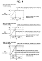
- FIGS. 4A to 4C illustrate the speed profiles for the smaller diameter region of the package 53.
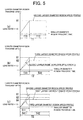
- FIGS. 5A to 5C illustrate the speed profiles for the larger diameter region of the package 53.
- the horizontal axis indicates the traverse time, and the vertical axis indicates the traverse speed.
- FIG. 4C illustrates the first smaller diameter region speed profile adjusted by the speed profile adjusting section 44 in the present embodiment.
- FIG. 5C illustrates the first larger diameter region speed profile adjusted by the speed profile adjusting section 44 in the present embodiment.
- a second smaller diameter region speed profile illustrated in FIG. 4A and a third smaller diameter region speed profile illustrated in FIG. 4B are illustrated in contrast to the first smaller diameter region speed profile.
- the second smaller diameter region speed profile, the third smaller diameter region speed profile, the second larger diameter region speed profile, and the third larger diameter region speed profile are set similar to the first embodiment, and hence the detailed description thereof will be omitted.
- FIGS. 4A to 4C illustrate only a case in which the speed of the traverse guide 17 is increased from the end in the smaller diameter region of the package 53 towards the central part in the width direction of the package 53 (a case in which the acceleration is positive), but a similar speed profile applies to a case in which the speed of the traverse guide 17 is reduced (a case in which the acceleration is negative).
- FIGS. 5A to 5C illustrate only a case in which the speed of the traverse guide 17 is increased from the end in the larger diameter region of the package 53 towards the central part in the width direction of the package 53 (a case in which the acceleration is positive), but a similar speed profile applies to a case in which the speed of the traverse guide 17 is reduced (a case in which the acceleration is negative).
- the acceleration is set to be smaller than the acceleration (v2/t11) in the third smaller diameter region speed profile and greater than the acceleration (V1/t11) in the second smaller diameter region speed profile.
- the traverse time t2 is made the same as the third smaller diameter region speed profile, and the traverse speed v4, the acceleration time t41, and the time t42 of traversing at the traverse speed v4 are differed from the third smaller diameter region speed profile so that the traverse distance and the average traverse speed become equal irrespective of the adjustment of the speed profile.
- the acceleration is set to be greater than the acceleration (V2/T11) in the third larger diameter region speed profile and smaller than the acceleration (V1/T11) in the second larger diameter region speed profile.
- the traverse time T2 is made the same as the third larger diameter region speed profile, and the traverse speed V4, the acceleration time T41, and the time T42 of traversing at the traverse speed V4 are differed from the third smaller diameter region speed profile so that the traverse distance and the average traverse speed become equal irrespective of the adjustment of the speed profile.
- the yarn winding device 11 according to the second embodiment described above has the following effects.
- the speed profile adjusting section 44 adjusts the acceleration of the traverse guide 17 in the first smaller diameter region speed profile to be smaller than the acceleration of the traverse guide 17 in the third smaller diameter region speed profile when the set lead ratio set by the lead ratio setting section 43 is greater than 1.0.
- the lead ratio greater than 1.0 is set, the peak of the current value of the traverse guide drive motor 19 in the smaller diameter region of the package 53 can be suppressed, and the increase in the heat generation amount of the traverse guide drive motor 19 can be suppressed.
- the traverse guide drive motor 19 can be operated at high speed in the smaller diameter region of the package 53, and the lowering in productivity of the yarn winding device 11 can be suppressed.
- the speed profile adjusting section 44 adjusts the acceleration of the traverse guide 17 in the first larger diameter region speed profile to greater than the acceleration of the traverse guide 17 in the third larger diameter region speed profile.
- the acceleration time of the traverse guide 17 for the first smaller diameter region speed profile is greater than the acceleration time of the traverse guide 17 for the third smaller diameter region speed profile.
- the acceleration time of the traverse guide 17 for the first larger diameter region speed profile is smaller than the acceleration time of the traverse guide 17 for the third larger diameter region speed profile.
- the speed linearly accelerates at the time of acceleration of the traverse guide 17, but the speed may also accelerate in a step-wise manner or in a curved manner.
- the acceleration of the traverse guide 17 in the first smaller diameter region speed profile is equal to the acceleration (v1/t11) of the traverse guide 17 in the second smaller diameter region speed profile, but the acceleration of the traverse guide 17 in the first smaller diameter region speed profile may be smaller than the acceleration (v1/t11) of the traverse guide 17 in the second smaller diameter region speed profile.
- the acceleration of the traverse guide 17 becomes smaller, but adjustment can be made to increase the acceleration time or to increase the traverse speed so that the traverse distance and the average traverse speed become equal irrespective of the adjustment of the speed profile.
- the acceleration of the traverse guide 17 in the first larger diameter region speed profile is equal to the acceleration (V1/T11) of the traverse guide 17 in the second larger diameter region speed profile, but the acceleration of the traverse guide 17 in the first larger diameter region speed profile may be greater than the acceleration (V1/T11) of the traverse guide 17 in the second larger diameter region speed profile.
- the acceleration of the traverse guide 17 becomes larger, but adjustment can be made to reduce the acceleration time or to reduce the traverse speed so that the traverse distance and the average traverse speed become equal irrespective of the adjustment of the speed profile.
- the first smaller diameter region speed profile and the first larger diameter region speed profile in the first embodiment and the second embodiment have the speed profile adjusted with a magnitude relationship of the acceleration of the traverse guide 17 as a reference with respect to the second smaller diameter region speed profile and the third smaller diameter region speed profile, and the second larger diameter region speed profile and the third larger diameter region speed profile, which are to be compared.
- the present invention is not limited thereto, and the speed profile may be adjusted with a magnitude relationship of the acceleration time of the traverse guide 17 as a reference.
- the lead ratio in the first embodiment and the second embodiment has been described as the value of the ratio of the traverse time, but the lead ratio may be set as the value of the ratio of the traverse speed. It should be noted that if the package 53 is wound by precision winding (method of winding the package 53 while maintaining the number of winds by the traverse device 12 at a constant value even if the wound diameter of the package 53 increases, where a traversing angle becomes smaller as the diameter of the package 53 increases), the package 53 cannot be wound at a predetermined number of winds unless the lead ratio is set as the value of the ratio of the traverse time.
- the package 53 can be wound even if the lead ratio is set as the value of the ratio of the traverse time or as the value of the ratio of the traverse speed.
- the configuration for controlling the operation of the yarn winding device 11 is not limited to the embodiments, and for example, the winding bobbin drive control section 31 and the traverse control section 34 may be arranged in the unit control section 41, or the lead ratio setting section 43 arranged in the machine control section 42 may be arranged in the unit control section 41.
- the winding bobbin B is directly driven by the winding bobbin drive motor 18, but a drive roller may be made in contact with the surface of the winding bobbin B to drive the winding bobbin B.
- the shape of the contact roller 14 is a conical shape in which the diameters of both ends are different, but the shape may also be a cylindrical shape in which the diameters of both ends are the same.
- the traverse device 12 is configured such that a longitudinal direction of the arm member 16 is parallel to an installing direction (vertical direction) of the yarn winding device 11, but the traverse device 12 may be configured such that the longitudinal direction of the arm member 16 is perpendicular to an installing surface of the yarn winding device 11.
- the traverse device 12 is configured such that the arm member 16 reciprocates by the traverse guide drive motor 19, but an endless timing belt may be arranged in proximity to the contact roller 14, the traverse guide 17 may be attached to the timing belt and the timing belt may be reciprocated by a pulse motor, or the like.
Landscapes
- Engineering & Computer Science (AREA)
- Microelectronics & Electronic Packaging (AREA)
- Winding Filamentary Materials (AREA)
Abstract
Description
- The present invention relates to a yarn winding device for winding yarn around a winding bobbin.
- As a yarn winding device that winds yarn around the winding bobbin while traversing, there is conventionally known a yarn winding device that changes a traverse speed of a traverse guide for a smaller diameter region and for a larger diameter region when producing a conical package (e.g., Japanese Unexamined Patent Publication No.
10-109823 - A value of a ratio of the traverse speed of the traverse guide within the smaller diameter region with respect to the traverse speed of the traverse guide within the larger diameter region of the conical package is referred to as a lead ratio. For example, if the ratio of the traverse speed of the traverse guide within the smaller diameter region and the traverse speed of the traverse guide within the larger diameter region is 1.3 : 1.0, the lead ratio is expressed as 1.3. The lead ratio may also be expressed as a value of a ratio of traverse time of the traverse guide within the larger diameter region with respect to traverse time of the traverse guide within the smaller diameter region.
- The traverse guide of the yarn winding device is driven by a traverse driving device such as a servo motor. The traverse driving device is required to be reversely operated to reverse the traverse guide at an end of the package. For example, when the lead ratio is set to 1.3, the traverse driving device is controlled so that the ratio of the traverse speed of the smaller diameter region to the traverse speed of the larger diameter region becomes 1.3 : 1.0
- However, when the lead ratio is greater than 1.0, the traverse speed of the smaller diameter region is increased compared to the case when the lead ratio is 1.0, and thus acceleration in reversing the traverse guide increases. As a result, a current supplied to the traverse driving device increases and a maximum current exceeding a rating may flow. A heat generation amount of the traverse driving device thus may increase or a limit torque may be easily achieved compared to a case when the lead ratio is 1.0 even under the same winding condition, thus leading to downgrade in specifications of the yarn winding device.
- It is an object of the present invention to provide an improved yarn winding device overcoming the above mentioned problems.
- This object is achieved by a yarn winding device of claim 1.
- In accordance with embodiments, the present invention provides a yarn winding device for driving a traverse guide at an appropriate speed profile when setting a lead ratio and producing a conical package. In accordance with further embodiments, the present invention provides a yarn winding device for suppressing a peak of a current value supplied to the traverse driving device and suppressing a heat generation amount of the traverse driving device by appropriately adjusting the speed profile in a smaller diameter region of the package when a lead ratio greater than 1.0 is set. In accordance with yet further embodiments, the present invention provides a yarn winding device for suppressing a saddle bag of the package by a quick turn of the traverse guide by appropriately adjusting the speed profile in a larger diameter region of the package when a lead ratio greater than 1.0 is set.
- According to a first aspect of the invention, a yarn winding device that produces a conical package includes a traverse guide, a traverse driving section, a lead ratio setting section, and a speed profile adjusting section. The traverse guide is adapted to traverse yarn to be wound into the package. The traverse driving section is adapted to reciprocate the traverse guide with respect to a direction of a winding width of the package. The lead ratio setting section is adapted to set a lead ratio as a set lead ratio, the lead ratio being a value of a ratio of traverse time of the traverse guide within a larger diameter region with respect to traverse time of the traverse guide within a smaller diameter region of the package, or a value of a ratio of traverse speed of the traverse guide within the smaller diameter region with respect to traverse time of the traverse guide within the larger diameter region of the package. The speed profile adjusting section is adapted to adjust a speed profile of the traverse guide in at least one of the larger diameter region and the smaller diameter region of the package according to the set lead ratio set by the lead ratio setting section.
- The speed profile of the traverse driving section thus can be freely adjusted according to the lead ratio. As a result, the traverse guide can be driven at an appropriate speed profile when setting the lead ratio and producing the conical package.
- A second aspect of the invention is the yarn winding device according to the first aspect, wherein the speed profile adjusting section adjusts the speed profile of the traverse guide for both the larger diameter region and the smaller diameter region of the package. The traverse guide thus can be driven at an appropriate speed profile in both the larger diameter region and the smaller diameter region when setting the lead ratio and producing the conical package.
- A third aspect of the invention is the yarn winding device according to the first or second aspect, wherein when the set lead ratio set by the lead ratio setting section is greater than 1.0, the speed profile adjusting section adjusts the speed profile for the smaller diameter region corresponding to the set lead ratio to a first smaller diameter region speed profile. Assume that a second smaller diameter region speed profile is the speed profile for the smaller diameter region corresponding to a reference lead ratio in which the lead ratio is 1.0. In this case, the speed profile adjusting section adjusts the speed profile such that acceleration of the traverse guide in the first smaller diameter region speed profile is at most acceleration of the traverse guide in the second smaller diameter region speed profile. Therefore, even when the lead ratio greater than 1.0 is set, the peak of the current value of the traverse driving section can be suppressed in the smaller diameter region of the package, and the increase in the heat generation amount of the traverse driving section can be suppressed. As a result, since the traverse driving section can be operated at high speed in the smaller diameter region of the package, lowering of productivity of the yarn winding device can be suppressed.
- A fourth aspect of the invention is the yarn winding device according to any of the first and second aspects, wherein when the set lead ratio set by the lead ratio setting section is greater than 1.0, the speed profile adjusting section adjusts the speed profile for the smaller diameter region corresponding to the set lead ratio to a first smaller diameter region speed profile. Assume that a second smaller diameter region speed profile is the speed profile for the smaller diameter region corresponding to a reference lead ratio in which the lead ratio is 1.0. Assume that a third smaller diameter region speed profile is the speed profile for the smaller diameter region in case the lead ratio is equal to the set lead ratio and acceleration time of the traverse guide is equal to acceleration time of the traverse guide in the second smaller diameter region speed profile. In this case, the speed profile adjusting section adjusts the speed profile such that acceleration of the traverse guide in the first smaller diameter region speed profile is smaller than acceleration of the traverse guide in the third smaller diameter region speed profile. Therefore, even when the lead ratio greater than 1.0 is set, the peak of the current value of the traverse driving section in the smaller diameter region of the package can be suppressed, and the increase in the heat generation amount of the traverse driving section can be suppressed. As a result, the traverse driving section can be operated at high speed in the smaller diameter region of the package, and the lowering in productivity of the yarn winding device can be suppressed.
- A fifth aspect of the invention is the yarn winding device according to any of the first and second aspects, wherein when the set lead ratio set by the lead ratio setting section is greater than 1.0, the speed profile adjusting section adjusts the speed profile for the larger diameter region corresponding to the set lead ratio to a first larger diameter region speed profile. Assume that a second larger diameter region speed profile is the speed profile of the larger diameter region corresponding to a reference lead ratio in which the lead ratio is 1.0. In this case, the speed profile adjusting section adjusts the speed profile such that acceleration of the traverse guide in the first larger diameter region speed profile is equal to or greater than acceleration of the traverse guide in the second larger diameter region speed profile. Therefore, if the lead ratio greater than 1.0 is set, the acceleration of the traverse guide in the larger diameter region of the package can be increased and the traverse guide can make a quick turn. As a result, the saddle bag in the larger diameter region of the package can be suppressed, and the conical package excelling in unwinding property can be produced.
- A sixth aspect of the invention is the yarn winding device according to any of the first and second aspects, wherein when the set lead ratio set by the lead ratio setting section is greater than 1.0, the speed profile adjusting section adjusts the speed profile for the larger diameter region corresponding to the set lead ratio to a first larger diameter region speed profile. Assume that a second larger diameter region speed profile is the speed profile for the larger diameter region corresponding to a reference lead ratio in which the lead ratio is 1.0. Assume that a third larger diameter region speed profile is the speed profile for the larger diameter region in case the lead ratio is equal to the set lead ratio and acceleration time of the traverse guide is equal to acceleration time of the traverse guide in the second larger diameter region speed profile. In this case, the speed profile adjusting section adjusts the speed profile such that acceleration of the traverse guide in the first larger diameter region speed profile is greater than acceleration of the traverse guide in the third larger diameter region speed profile. Therefore, even when the lead ratio greater than 1.0 is set, the acceleration of the traverse guide in the larger diameter region of the package can be increased and the traverse guide can make a quick turn. As a result, the saddle bag in the larger diameter region of the package can be suppressed, and the conical package excelling in unwinding property can be produced.
- A seventh aspect of the invention is the yarn winding device according to the third aspect, wherein an acceleration time of the traverse guide for the first smaller diameter region speed profile is equal to or greater than an acceleration time of the traverse guide for the second smaller diameter region speed profile. Thus, when the lead ratio greater than 1.0 is set, the traverse guide makes a turn in the smaller diameter region of the package by taking time. Therefore, the peak of the current value of the traverse driving section can be suppressed and the increase in the heat generation amount of the traverse driving section can be suppressed. As a result, the traverse driving section can be operated at high speed in the smaller diameter region of the package, and the productivity of the yarn winding device can be improved.
- An eighth aspect of the invention is the yarn winding device according to the fourth aspect, wherein an acceleration time of the traverse guide for the first smaller diameter region speed profile is greater than an acceleration time of the traverse guide for the third smaller diameter region speed profile. Thus, when the lead ratio greater than 1.0 is set, the traverse guide makes a turn in the smaller diameter region of the package by taking time. Therefore, the peak of the current value of the traverse driving section can be suppressed and the increase in the heat generation amount of the traverse driving section can be suppressed. As a result, the traverse driving section can be operated at high speed in the smaller diameter region of the package, and the lowering in productivity of the yarn winding device can be suppressed.
- A ninth aspect of the invention is the yarn winding device according to the fifth aspect, wherein acceleration time of the traverse guide for the first larger diameter region speed profile is at most acceleration time of the traverse guide for the second larger diameter region speed profile. Therefore, even when the lead ratio greater than 1.0 is set, the acceleration of the traverse guide in the larger diameter region of the package can be increased and the traverse guide can make a quick turn. As a result, the saddle bag in the larger diameter region of the package can be suppressed, and the conical package excelling in unwinding property can be produced.
- A tenth aspect of the invention is the yarn winding device according to the sixth aspect, wherein the acceleration time of the traverse guide for the first larger diameter region speed profile is set shorter than the acceleration time of the traverse guide for the third larger diameter region speed profile. Therefore, even when the lead ratio greater than 1.0 is set, the acceleration of the traverse guide in the larger diameter region of the package can be increased and the traverse guide can make a quick turn. As a result, the saddle bag in the larger diameter region of the package can be suppressed, and the conical package excelling in unwinding property can be produced.
-
-
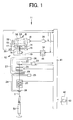
FIG. 1 is a front schematic view and a block diagram illustrating ayarn winding device 11 according to a first embodiment of the present invention; -
FIGS. 2A to 2C are diagrams illustrating speed profiles of a smaller diameter region of apackage 53 according to the first embodiment; -
FIGS. 3A to 3C are diagrams illustrating speed profiles of a larger diameter region of thepackage 53 according to the first embodiment; -
FIGS. 4A to 4C are diagrams illustrating speed profiles of a smaller diameter region of thepackage 53 according to a second embodiment; and -
FIGS. 5A to 5C are diagrams illustrating speed profiles of a larger diameter region of thepackage 53 according to the second embodiment. - Embodiments of the present invention will now be described with reference to the drawings.
- A
yarn winding device 11 according to a first embodiment of the present invention will be described with reference toFIGS. 1 to 3C . - As illustrated in
FIG. 1 , theyarn winding device 11 of the present embodiment is a yarn winding device that forms a yarn layer by winding yarn Y of ayarn feeding bobbin 51 around a windingtube 52 while traversing the yarn Y with atraverse device 12 to produce aconical package 53. Although oneyarn winding device 11 is illustrated inFIG. 1 , a plurality ofyarn winding devices 11 may be arranged in line to configure an automatic winder. - In this specification, the winding
tube 52 and thepackage 53 are collectively referred to as a winding bobbin B. In other words, the winding bobbin B in which the yarn layer is not formed is the windingtube 52, and the winding bobbin B in which the yarn layer is formed is thepackage 53. A smaller diameter region and a larger diameter region of thepackage 53 respectively indicate regions of a smaller diameter half and a larger diameter half with a central part in a width direction of thepackage 53 as a boundary. - An overview of the
yarn winding device 11 will be described first. As illustrated inFIG. 1 , theyarn winding device 11 includes acradle 13 for supporting the winding bobbin B in an attachable/detachable manner, and acontact roller 14 driven and rotated while making contact with a peripheral surface of the winding bobbin B. Thecradle 13 is configured to freely swing withswing shaft 15 as a center, and supports both ends of the winding bobbin B in a freely rotating manner. When the yarn Y is wound around the winding bobbin B and a diameter of the winding bobbin B is increased, thecradle 13 swings so that an appropriate contact between the peripheral surface of the winding bobbin B and thecontact roller 14 is maintained. - The
cradle 13 includes a windingbobbin drive motor 18 serving as a winding bobbin driving section. When the winding bobbin B is set to thecradle 13, a drive shaft of the windingbobbin drive motor 18 is coupled to the winding bobbin B in a relatively non-rotatable manner (so-called direct drive method). Theyarn winding device 11 winds the yarn Y into thepackage 53 by actively rotation driving the winding bobbin B with the windingbobbin drive motor 18. - The
cradle 13 is provided with a winding bobbinrotation speed sensor 32 and a windingbobbin diameter sensor 33. The winding bobbinrotation speed sensor 32 detects a rotation speed of the winding bobbin B. The windingbobbin diameter sensor 33 detects a diameter of the winding bobbin B. The windingbobbin diameter sensor 33 is a rotary encoder or the like, and detects the diameter of the winding bobbin B by detecting a swing angle of thecradle 13. - The
traverse device 12 is arranged in proximity to thecontact roller 14. The yarn Y is wound around the winding bobbin B while being traversed by thetraverse device 12. Thetraverse device 12 includes atraverse guide 17 and a traverse guide drivemotor 19 serving as a traverse driving section. Thetraverse guide 17 engages with the yarn Y to traverse the yarn Y. The traverse guide drivemotor 19 reciprocates thetraverse guide 17 with respect to a direction of the winding width of the winding bobbin B. Thetraverse guide 17 is arranged at a tip of anarm member 16 configured to freely oscillate. Thetraverse guide 17 is reciprocated by reciprocating thearm member 16 with the traverse guide drivemotor 19 as illustrated with an arrow inFIG. 1 . In the present embodiment, a servo motor is used for the traverse guide drivemotor 19, but a step motor or the like may also be used. - A
tension applying device 20, ayarn splicing device 21, and ayarn clearer 22 are arranged in order from theyarn feeding bobbin 51 side on a yarn travelling path between theyarn feeding bobbin 51 and thecontact roller 14. Thetension applying device 20 applies an appropriate tension to the yarn Y. Theyarn clearer 22 detects a thickness of the yarn Y passing through a detecting section by a sensor, and analyzes a signal from the sensor by ananalyzer 23 to detect a yarn defect such as slub. Theyarn clearer 22 is provided with a cutter for immediately cutting the yarn Y when the yarn defect is detected. Theyarn splicing device 21 splices a lower yarn from theyarn feeding bobbin 51 and an upper yarn from the winding bobbin B after theyarn clearer 22 detects the yarn defect and cuts the yarn, or after yarn breakage of the yarn Y from theyarn feeding bobbin 51. - A lower yarn catching and guiding
section 24 for sucking and catching the lower yarn from theyarn feeding bobbin 51 and guiding the same to theyarn splicing device 21 is arranged upstream of theyarn splicing device 21. An upper yarn catching and guidingsection 27 for sucking and catching the upper yarn from the winding bobbin B and guiding the same to theyarn splicing device 21 is arranged downstream of theyarn splicing device 21. The lower yarn catching and guidingsection 24 is formed in a pipe shape, and is arranged capable of swinging in a vertical direction with ashaft 25 as the center. Asuction hole 26 is formed at a distal end side of the lower yarn catching and guidingsection 24. The upper yarn catching and guidingsection 27 is also formed in a pipe shape, and is arranged capable of swinging in the vertical direction with ashaft 28 as the center. Amouth 29 is arranged at the distal end side of the upper yarn catching and guidingsection 27. The lower yarn catching and guidingsection 26 and the upper yarn catching and guidingsection 27 are respectively connected to a negative pressure source to cause thesuction hole 26 and themouth 29 at the distal ends to generate a sucking force. - A configuration for controlling an operation of the
yarn winding device 11 will now be described. In the present embodiment, as illustrated inFIG. 1 , the windingbobbin drive motor 18 for driving the winding bobbin B and the traverse guide drivemotor 19 for driving thetraverse guide 17 are separately and independently arranged, so that the drive of the winding bobbin B and thetraverse guide 17 is separately and independently controlled. The drive of thetraverse guide 17 by the traverse guide drivemotor 19 is controlled based on a speed profile. - The speed profile is information on the drive of the
traverse guide 17, and includes the setting of a traverse time of thetraverse guide 17, a traverse speed, an acceleration time of thetraverse guide 17, acceleration of thetraverse guide 17, and the like. The speed profile is adjusted separately for the smaller diameter region and the larger diameter region of thepackage 53. Herein, "adjusted separately" also means adjusting individually or independently for the smaller diameter region and the larger diameter region. In the smaller diameter region of thepackage 53, the drive of thetraverse guide 17 is controlled based on a first smaller diameter region speed profile. In the larger diameter region of thepackage 53, the drive of thetraverse guide 17 is controlled based on a first larger diameter region speed profile. - A lead ratio is a value of the ratio of the traverse speed of the
traverse guide 17 within the smaller diameter region with respect to the traverse speed of thetraverse guide 17 within the larger diameter region in theconical package 53 described above. For example, if the ratio of the traverse speed of thetraverse guide 17 within the smaller diameter region and the traverse speed of thetraverse guide 17 within the larger diameter region is set to 1.3 : 1.0, the lead ratio is expressed as 1.3. The lead ratio may also be expressed in percentages such as 130 percent : 100 percent. The lead ratio may not be expressed with the value of the ratio of the traverse speeds, but may be expressed with the value of the ratio of the traverse time, that is, the value of the ratio of the traverse time of thetraverse guide 17 within the larger diameter region with respect to the traverse time of thetraverse guide 17 within the smaller diameter region. In the present embodiment, the lead ratio will be described as the value of the ratio of the traverse time. - As illustrated in
FIG. 1 , theyarn winding device 11 includes aunit control section 41 for individually controlling theyarn winding device 11. Theunit control section 41 is connected with a winding bobbindrive control section 31 and atraverse control section 34. The winding bobbindrive control section 31 controls drive and stop of the windingbobbin drive motor 18 based on a control signal from theunit control section 41. Thetraverse control section 34 controls drive and stop of the traverse guide drivemotor 19 based on a control signal from theunit control section 41. Theunit control section 41 is connected to amachine control section 42. Themachine control section 42 collectively controls a plurality ofyarn winding devices 11 that configure the automatic winder. - The
unit control section 41, themachine control section 42, the winding bobbindrive control section 31, and thetraverse control section 34 include a Central Processing Unit (CPU) serving as an operating section, a Read Only Memory (ROM), a Random Access Memory (RAM) or the like serving as a storage device, and the like. The ROM of thetraverse control section 34 stores control software for causing hardware such as the CPU arranged in thetraverse control section 34 to operate as a control section based on the speed profile. - A rotation speed signal of the winding bobbin B detected by the winding bobbin
rotation speed sensor 32 is transmitted to theunit control section 41, the winding bobbindrive control section 31, and thetraverse control section 34. A diameter signal of the winding bobbin B detected by the windingbobbin diameter sensor 33 is transmitted to theunit control section 41, and is transferred from theunit control section 41 to the winding bobbindrive control section 31 and thetraverse control section 34. - The
machine control section 42 includes a leadratio setting section 43. Thetraverse control section 34 includes a speedprofile adjusting section 44. The leadratio setting section 43 sets the value of the ratio of the traverse time of thetraverse guide 17 within the larger diameter region with respect to the traverse time of thetraverse guide 17 within the smaller diameter region of thepackage 53 as the lead ratio (e.g., 1.3). The lead ratio that is set is a set lead ratio. The speedprofile adjusting section 44 adjusts the first smaller diameter region speed profile and the first larger diameter region speed profile according to the set lead ratio (seeFIGS. 2C and3C ). The first smaller diameter region speed profile and the first larger diameter region speed profile will be described in detail later. - The
machine control section 42 transmits the set lead ratio set by the leadratio setting section 43 to theunit control section 41 of theyarn winding device 11. Theunit control section 41 transmits the received set lead ratio to thetraverse control section 34. When receiving the set lead ratio, thetraverse control section 34 controls the drive and stop of the traverse guide drivemotor 19 so as to drive thetraverse guide 17 according to the first smaller diameter region speed profile and the first larger diameter region speed profile determined based on the set lead ratio. - Next, the first smaller diameter region speed profile and the first larger diameter region speed profile adjusted by the speed
profile adjusting section 44 in theyarn winding device 11 of the present embodiment will be described. -
FIGS. 2A to 2C illustrate the speed profiles of the smaller diameter region of thepackage 53.FIGS. 3A to 3C illustrate the speed profiles of the larger diameter region of thepackage 53. A horizontal axis indicates the traverse time, and a vertical axis indicates the traverse speed.FIG. 2C illustrates the first smaller diameter region speed profile adjusted by the speedprofile adjusting section 44 in the present embodiment.FIG. 3C illustrates the first larger diameter region speed profile. A second smaller diameter region speed profile illustrated inFIG. 2A and a third smaller diameter region speed profile illustrated inFIG. 2B are illustrated in contrast to the first smaller diameter region speed profile. A second larger diameter region speed profile illustrated inFIG. 3A and a third larger diameter region speed profile illustrated inFIG. 3B are illustrated in contrast to the first larger diameter region speed profile. -
FIGS. 2A to 2C illustrate only a case in which the speed of thetraverse guide 17 is increased from the end in the smaller diameter region of thepackage 53 towards the central part in the width direction of the package 53 (a case in which the acceleration is positive), but a similar speed profile applies to a case in which the speed of thetraverse guide 17 is reduced (a case in which the acceleration is negative).FIGS. 3A to 3C illustrate only a case in which the speed of thetraverse guide 17 is increased from the end in the larger diameter region of thepackage 53 towards the central part in the width direction of the package 53 (a case in which the acceleration is positive), but similar speed profile applies to a case in which the speed of thetraverse guide 17 is reduced (a case in which the acceleration is negative). - The second smaller diameter region speed profile illustrated in
FIG. 2A is the speed profile for the smaller diameter region when the lead ratio is 1.0. The second larger diameter region speed profile illustrated inFIG. 3A is the speed profile for the larger diameter region when the lead ratio is 1.0. The case in which the lead ratio is 1.0 is the case in which the set lead ratio becomes 1.0 by operating the leadratio setting section 43 and inputting 1.0 for the lead ratio. The lead ratio of 1.0, will be referred to as a "reference lead ratio". Since the lead ratio is not set if a function of the leadratio setting section 43 is turned OFF, the lead ratio may not be provided, that is, the set lead ratio may be 1.0. - A determining condition of the second smaller diameter region speed profile and the second larger diameter region speed profile is determined by a winding condition of the
conical package 53. The determining condition of the second smaller diameter region speed profile includes a traverse time t1, a traverse speed v1, an acceleration time t11 of thetraverse guide 17, acceleration v1/t11 of thetraverse guide 17, and the like. The determining condition of the second larger diameter region speed profile includes a traverse time T1, a traverse speed V1, an acceleration time T11 of thetraverse guide 17, acceleration V1/T11 of thetraverse guide 17, and the like. The winding condition includes a winding width, the number of winds, and a manner of winding (precision winding, random winding, etc.). The second smaller diameter region speed profile and the second larger diameter region speed profile of the present embodiment have the traverse time t1 of the smaller diameter region and the traverse time T1 of the larger diameter region set equal, the traverse speed v1 of the smaller diameter region and the traverse speed V1 of the larger diameter region set equal, the acceleration time t11 of the smaller diameter region and the acceleration time T11 of the larger diameter region set equal, and the acceleration (v1/t11) of the smaller diameter region and the acceleration (V11/T11) of the larger diameter region set equal. - The third smaller diameter region speed profile illustrated in
FIG. 2B , is a speed profile for the smaller diameter region when the lead ratio same as the set lead ratio (e.g., 1.3) is set. The third larger diameter region speed profile illustrated inFIG. 3B is a speed profile for the larger diameter region when the lead ratio same as the set lead ratio (e.g., 1.3) is set. - Comparing the second smaller diameter region speed profile and the third smaller diameter region speed profile based on
FIGS. 2A and 2B , since the lead ratios are different, i.e., 1.0 and 1.3, the traverse time t2 in the third smaller diameter region speed profile is reduced than the traverse time t1 in the second smaller diameter region speed profile. Thetraverse guide 17 is required to be moved to the central part in the width direction of thepackage 53 by the traverse time t2 that is shorter than the traverse time t1, and thus the traverse speed v2 in the third smaller diameter region speed profile is increased than the traverse speed v1 in the second smaller diameter region speed profile by the reduction of the traverse time t2. The acceleration time t11 in the third smaller diameter region speed profile is the same as the acceleration time t11 in the second smaller diameter region speed profile. Therefore, the acceleration (v2/t11) in the third smaller diameter region speed profile is increased than the acceleration (v1/t11) in the second smaller diameter region speed profile. - Therefore, if the speed profile in which the acceleration of the
traverse guide 17 is increased is set for the smaller diameter region of thepackage 53, the current to be supplied to the traverse guide drivemotor 19 increases and a maximum current exceeding the rating may flow. Accordingly, even under the same winding condition, the heat generation amount of the traverse guide drivemotor 19 thus may be increased or the limit torque may be easily reached compared to the case when the lead ratio is 1.0, thus leading to downgrade in specifications of theyarn winding device 11. - In order to resolve such problems, as illustrated in
FIG. 2C , in the first smaller diameter region speed profile of the present embodiment, the acceleration is at most the acceleration (v1/t11) in the second smaller diameter region speed profile in which the lead ratio is 1.0. Specifically, the acceleration in the first smaller diameter region speed profile is made equal to the acceleration (v1/t11) in the second smaller diameter region speed profile. In the first smaller diameter region speed profile, the acceleration is reduced, but the traverse time t2 is made the same as the third smaller diameter region speed profile, and the traverse speed v3, the acceleration time t31, and the time t32 of traversing at the traverse speed v3 are differed from the third smaller diameter region speed profile so that the traverse distance and the average traverse speed become equal irrespective of the adjustment of the speed profile. - Next, the second larger diameter region speed profile and the third larger diameter region speed profile are compared with reference to
FIGS. 3A and 3B . Since the lead ratios are different, i.e., 1.0 and 1.3, the traverse time T2 in the third larger diameter region speed profile is increased than the traverse time T1 in the second larger diameter region speed profile. Thetraverse guide 17 is required to be moved to the central part in the width direction of thepackage 53 by the traverse time T2 that is longer than the traverse time T1. Thus, the traverse speed V2 in the third larger diameter region speed profile is reduced than the traverse speed V1 in the second larger diameter region speed profile by the increase of the traverse time T2. The acceleration time T11 in the third larger diameter region speed profile is the same as the acceleration time T11 in the second larger diameter region speed profile. Therefore, the acceleration (V2/T11) in the third larger diameter region speed profile is reduced than the acceleration (V1/T11) in the second larger diameter region speed profile. - In the first larger diameter region speed profile of the present embodiment, in order to solve the problem of the saddle bag, as illustrated in
FIG. 3C , the acceleration is equal to or greater than the acceleration (V1/T11) in the second larger diameter region speed profile in which the lead ratio is 1.0. Specifically, the acceleration in the first larger diameter region speed profile is made equal to the acceleration (V1/T11) in the second larger diameter region speed profile. The acceleration is set large in the first larger diameter region speed profile. However, the traverse time T2 is made the same as the third larger diameter region speed profile, and the traverse speed V3, the acceleration time T31, and the time T32 of traversing at the traverse speed V3 are differed from the third larger diameter region speed profile so that the traverse distance and the average traverse speed become equal irrespective of the adjustment of the speed profile. - The
yarn winding device 11 according to the first embodiment described above has the following effects. - The speed
profile adjusting section 44 adjusts the speed profile of thetraverse guide 17 in both the larger diameter region and the smaller diameter region of thepackage 53. Thus, when setting the lead ratio and producing theconical package 53, thetraverse guide 17 can be driven at the appropriate speed profile in both the larger diameter region and the smaller diameter region. - When the set lead ratio set by the lead
ratio setting section 43 is greater than 1.0, the speedprofile adjusting section 44 adjusts the acceleration of thetraverse guide 17 in the first smaller diameter region speed profile to at most the acceleration of thetraverse guide 17 in the second smaller diameter region speed profile. Thus, when the lead ratio greater than 1.0 is set, the peak of the current value of the traverse guide drivemotor 19 in the smaller diameter region of thepackage 53 can be suppressed, and the increase in the heat generation amount of the traverse guide drivemotor 19 can be suppressed. As a result, the traverse guide drivemotor 19 can be operated at high speed in the smaller diameter region of thepackage 53, and the lowering in productivity of theyarn winding device 11 can be suppressed. - When the set lead ratio set by the lead
ratio setting section 43 is greater than 1.0, the speedprofile adjusting section 44 adjusts the acceleration of thetraverse guide 17 in the first larger diameter region speed profile to be equal to or greater than the acceleration of thetraverse guide 17 in the second larger diameter region speed profile in which the lead ratio is 1.0. Thus, when the lead ratio greater than 1.0 is set, the acceleration of thetraverse guide 17 in the larger diameter region of thepackage 53 can be made large, and thetraverse guide 17 can make a quick turn. As a result, the saddle bag in the larger diameter region of thepackage 53 can be suppressed, and theconical package 53 excelling in unwinding property can be produced. - The acceleration time of the
traverse guide 17 for the first smaller diameter region speed profile is equal to or greater than the acceleration time of thetraverse guide 17 for the second smaller diameter region speed profile. Thus, when the lead ratio greater than 1.0 is set, thetraverse guide 17 makes a turn in the smaller diameter region of thepackage 53 by taking time. Therefore, the peak of the current value of the traverse guide drivemotor 19 can be suppressed, and the increase in the heat generation amount of the traverse guide drivemotor 19 can be suppressed. As a result, the traverse guide drivemotor 19 can be operated at high speed in the smaller diameter region of thepackage 53, and the lowering in productivity of theyarn winding device 11 can be suppressed. - The acceleration time of the
traverse guide 17 for the first larger diameter region speed profile is at most the acceleration time of thetraverse guide 17 for the second larger diameter region speed profile. Thus, when the lead ratio greater than 1.0 is set, the acceleration of thetraverse guide 17 in the larger diameter region of thepackage 53 can be made large, and thetraverse guide 17 can make a quick turn. As a result, the saddle bag in the larger diameter region of thepackage 53 can be suppressed, and theconical package 53 excelling in unwinding property can be produced. - The
yarn winding device 11 according to a second embodiment of the present invention will be described with reference toFIGS. 4A to 4C andFIGS. 5A to 5C . Theyarn winding device 11 according to the present embodiment greatly differs from the first embodiment in the following two points. A first difference lies in that the acceleration of thetraverse guide 17 in the first smaller diameter region speed profile is smaller than the acceleration of thetraverse guide 17 in the third smaller diameter region speed profile, and greater than the acceleration of thetraverse guide 17 in the second smaller diameter region speed profile. A second difference lies in that the acceleration of thetraverse guide 17 in the first larger diameter region speed profile is greater than the acceleration of thetraverse guide 17 in the third larger diameter region speed profile, and smaller than the acceleration of thetraverse guide 17 in the second larger diameter region speed profile. Other configurations and controls are similar to the first embodiment, and hence the detailed description thereof will be omitted. -
FIGS. 4A to 4C illustrate the speed profiles for the smaller diameter region of thepackage 53.FIGS. 5A to 5C illustrate the speed profiles for the larger diameter region of thepackage 53. The horizontal axis indicates the traverse time, and the vertical axis indicates the traverse speed.FIG. 4C illustrates the first smaller diameter region speed profile adjusted by the speedprofile adjusting section 44 in the present embodiment.FIG. 5C illustrates the first larger diameter region speed profile adjusted by the speedprofile adjusting section 44 in the present embodiment. A second smaller diameter region speed profile illustrated inFIG. 4A and a third smaller diameter region speed profile illustrated inFIG. 4B are illustrated in contrast to the first smaller diameter region speed profile. A second larger diameter region speed profile illustrated inFIG. 5A and a third larger diameter region speed profile illustrated inFIG. 5B are illustrated in contrast to the first larger diameter region speed profile. The second smaller diameter region speed profile, the third smaller diameter region speed profile, the second larger diameter region speed profile, and the third larger diameter region speed profile are set similar to the first embodiment, and hence the detailed description thereof will be omitted. -
FIGS. 4A to 4C illustrate only a case in which the speed of thetraverse guide 17 is increased from the end in the smaller diameter region of thepackage 53 towards the central part in the width direction of the package 53 (a case in which the acceleration is positive), but a similar speed profile applies to a case in which the speed of thetraverse guide 17 is reduced (a case in which the acceleration is negative).FIGS. 5A to 5C illustrate only a case in which the speed of thetraverse guide 17 is increased from the end in the larger diameter region of thepackage 53 towards the central part in the width direction of the package 53 (a case in which the acceleration is positive), but a similar speed profile applies to a case in which the speed of thetraverse guide 17 is reduced (a case in which the acceleration is negative). - As illustrated in
FIG. 4C , in the first smaller diameter region speed profile of the present embodiment, the acceleration is set to be smaller than the acceleration (v2/t11) in the third smaller diameter region speed profile and greater than the acceleration (V1/t11) in the second smaller diameter region speed profile. In the first smaller diameter region speed profile, the traverse time t2 is made the same as the third smaller diameter region speed profile, and the traverse speed v4, the acceleration time t41, and the time t42 of traversing at the traverse speed v4 are differed from the third smaller diameter region speed profile so that the traverse distance and the average traverse speed become equal irrespective of the adjustment of the speed profile. - As illustrated in
FIG. 5C , in the first larger diameter region speed profile of the present embodiment, the acceleration is set to be greater than the acceleration (V2/T11) in the third larger diameter region speed profile and smaller than the acceleration (V1/T11) in the second larger diameter region speed profile. In the first larger diameter region speed profile, the traverse time T2 is made the same as the third larger diameter region speed profile, and the traverse speed V4, the acceleration time T41, and the time T42 of traversing at the traverse speed V4 are differed from the third smaller diameter region speed profile so that the traverse distance and the average traverse speed become equal irrespective of the adjustment of the speed profile. - The
yarn winding device 11 according to the second embodiment described above has the following effects. - The speed
profile adjusting section 44 adjusts the acceleration of thetraverse guide 17 in the first smaller diameter region speed profile to be smaller than the acceleration of thetraverse guide 17 in the third smaller diameter region speed profile when the set lead ratio set by the leadratio setting section 43 is greater than 1.0. Thus, when the lead ratio greater than 1.0 is set, the peak of the current value of the traverse guide drivemotor 19 in the smaller diameter region of thepackage 53 can be suppressed, and the increase in the heat generation amount of the traverse guide drivemotor 19 can be suppressed. As a result, the traverse guide drivemotor 19 can be operated at high speed in the smaller diameter region of thepackage 53, and the lowering in productivity of theyarn winding device 11 can be suppressed. - When the set lead ratio set by the lead
ratio setting section 43 is greater than 1.0, the speedprofile adjusting section 44 adjusts the acceleration of thetraverse guide 17 in the first larger diameter region speed profile to greater than the acceleration of thetraverse guide 17 in the third larger diameter region speed profile. Thus, when the lead ratio greater than 1.0 is set, the acceleration of thetraverse guide 17 in the larger diameter region of thepackage 53 can be made large, and thetraverse guide 17 can make a quick turn. As a result, the saddle bag in the larger diameter region of thepackage 53 can be suppressed, and theconical package 53 excelling in unwinding property can be produced. - The acceleration time of the
traverse guide 17 for the first smaller diameter region speed profile is greater than the acceleration time of thetraverse guide 17 for the third smaller diameter region speed profile. Thus, when the lead ratio greater than 1.0 is set, thetraverse guide 17 makes a turn in the smaller diameter region of thepackage 53 by taking time. Therefore, the peak of the current value of the traverse guide drivemotor 19 can be suppressed, and the increase in the heat generation amount of the traverse guide drivemotor 19 can be suppressed. As a result, the traverse guide drivemotor 19 can be operated at high speed in the smaller diameter region of thepackage 53, and the lowering in productivity of theyarn winding device 11 can be suppressed. - The acceleration time of the
traverse guide 17 for the first larger diameter region speed profile is smaller than the acceleration time of thetraverse guide 17 for the third larger diameter region speed profile. Thus, when the lead ratio greater than 1.0 is set, the acceleration of thetraverse guide 17 in the larger diameter region of thepackage 53 can be made large. Thetraverse guide 17 thus can make a quick turn. As a result, the saddle bag in the larger diameter region of thepackage 53 can be suppressed, and theconical package 53 excelling in unwinding property can be produced. - The embodiments of the present invention have been described above, but the present invention is not limited to the above-described embodiments, and various modifications may be made. For example, the speed linearly accelerates at the time of acceleration of the
traverse guide 17, but the speed may also accelerate in a step-wise manner or in a curved manner. - In the first embodiment, the acceleration of the
traverse guide 17 in the first smaller diameter region speed profile is equal to the acceleration (v1/t11) of thetraverse guide 17 in the second smaller diameter region speed profile, but the acceleration of thetraverse guide 17 in the first smaller diameter region speed profile may be smaller than the acceleration (v1/t11) of thetraverse guide 17 in the second smaller diameter region speed profile. In this case, the acceleration of thetraverse guide 17 becomes smaller, but adjustment can be made to increase the acceleration time or to increase the traverse speed so that the traverse distance and the average traverse speed become equal irrespective of the adjustment of the speed profile. Similarly, the acceleration of thetraverse guide 17 in the first larger diameter region speed profile is equal to the acceleration (V1/T11) of thetraverse guide 17 in the second larger diameter region speed profile, but the acceleration of thetraverse guide 17 in the first larger diameter region speed profile may be greater than the acceleration (V1/T11) of thetraverse guide 17 in the second larger diameter region speed profile. In this case, the acceleration of thetraverse guide 17 becomes larger, but adjustment can be made to reduce the acceleration time or to reduce the traverse speed so that the traverse distance and the average traverse speed become equal irrespective of the adjustment of the speed profile. - The first smaller diameter region speed profile and the first larger diameter region speed profile in the first embodiment and the second embodiment have the speed profile adjusted with a magnitude relationship of the acceleration of the
traverse guide 17 as a reference with respect to the second smaller diameter region speed profile and the third smaller diameter region speed profile, and the second larger diameter region speed profile and the third larger diameter region speed profile, which are to be compared. However, the present invention is not limited thereto, and the speed profile may be adjusted with a magnitude relationship of the acceleration time of thetraverse guide 17 as a reference. - The lead ratio in the first embodiment and the second embodiment has been described as the value of the ratio of the traverse time, but the lead ratio may be set as the value of the ratio of the traverse speed. It should be noted that if the
package 53 is wound by precision winding (method of winding thepackage 53 while maintaining the number of winds by thetraverse device 12 at a constant value even if the wound diameter of thepackage 53 increases, where a traversing angle becomes smaller as the diameter of thepackage 53 increases), thepackage 53 cannot be wound at a predetermined number of winds unless the lead ratio is set as the value of the ratio of the traverse time. On the other hand, if thepackage 53 is wound by random winding (method of winding thepackage 53 at a constant winding speed and a constant traverse speed, where the number of winds changes with change in the diameter of the package 53), thepackage 53 can be wound even if the lead ratio is set as the value of the ratio of the traverse time or as the value of the ratio of the traverse speed. - The configuration for controlling the operation of the
yarn winding device 11 is not limited to the embodiments, and for example, the winding bobbindrive control section 31 and thetraverse control section 34 may be arranged in theunit control section 41, or the leadratio setting section 43 arranged in themachine control section 42 may be arranged in theunit control section 41. - The winding bobbin B is directly driven by the winding
bobbin drive motor 18, but a drive roller may be made in contact with the surface of the winding bobbin B to drive the winding bobbin B. The shape of thecontact roller 14 is a conical shape in which the diameters of both ends are different, but the shape may also be a cylindrical shape in which the diameters of both ends are the same. - The
traverse device 12 is configured such that a longitudinal direction of thearm member 16 is parallel to an installing direction (vertical direction) of theyarn winding device 11, but thetraverse device 12 may be configured such that the longitudinal direction of thearm member 16 is perpendicular to an installing surface of theyarn winding device 11. Thetraverse device 12 is configured such that thearm member 16 reciprocates by the traverse guide drivemotor 19, but an endless timing belt may be arranged in proximity to thecontact roller 14, thetraverse guide 17 may be attached to the timing belt and the timing belt may be reciprocated by a pulse motor, or the like. - The technical scope of the present invention described above is not limited to the above-described embodiments, and is not limited to the shapes of the above-described embodiments. The technical scope of the present invention widely encompasses the entire range of the technical scope truly intended by the present invention, which is apparent from the present specification and the matters described in the drawings.
Claims (10)
- A yarn winding device that produces a conical package, comprising:a traverse guide (17) adapted to traverse yarn to be wound into the package;a traverse driving section (19) adapted to reciprocate the traverse guide (17) with respect to a direction of a winding width of the package;a lead ratio setting section (43) adapted to set a lead ratio as a set lead ratio, the lead ratio being a value of a ratio of traverse time of the traverse guide (17) within a larger diameter region with respect to traverse time of the traverse guide (17) within a smaller diameter region of the package, or a value of a ratio of traverse speed of the traverse guide (17) within the smaller diameter region with respect to traverse time of the traverse guide (17) within the larger diameter region of the package; anda speed profile adjusting section (44) adapted to adjust a speed profile of the traverse guide (17) in at least one of the larger diameter region and the smaller diameter region of the package according to the set lead ratio set by the lead ratio setting section (43).
- The yarn winding device according to claim 1, wherein the speed profile adjusting section (44) is adapted to adjust the speed profile of the traverse guide (17) for both the larger diameter region and the smaller diameter region of the package.
- The yarn winding device according to claim 1 or claim 2, wherein when the set lead ratio set by the lead ratio setting section (43) is greater than 1.0, the speed profile adjusting section (44) is adapted to adjust the speed profile for the smaller diameter region corresponding to the set lead ratio to a first smaller diameter region speed profile, and
provided that a second smaller diameter region speed profile is the speed profile for the smaller diameter region corresponding to a reference lead ratio in which the lead ratio is 1.0, the speed profile adjusting section (44) is adapted to adjust acceleration of the traverse guide (17) in the first smaller diameter region speed profile to be at most acceleration of the traverse guide (17) in the second smaller diameter region speed profile. - The yarn winding device according to claim 1 or claim 2, wherein when the set lead ratio set by the lead ratio setting section (43) is greater than 1.0, the speed profile adjusting section (44) is adapted to adjust the speed profile for the smaller diameter region corresponding to the set lead ratio to a first smaller diameter region speed profile,
provided that a second smaller diameter region speed profile is the speed profile for the smaller diameter region corresponding to a reference lead ratio in which the lead ratio is 1.0, and a third smaller diameter region speed profile is the speed profile for the smaller diameter region in case the lead ratio is equal to the set lead ratio and acceleration time of the traverse guide (17) is equal to acceleration time of the traverse guide (17) in the second smaller diameter region speed profile,
the speed profile adjusting section (44) is adapted to adjust acceleration of the traverse guide (17) in the first smaller diameter region speed profile to be smaller than acceleration of the traverse guide (17) in the third smaller diameter region speed profile. - The yarn winding device according to claim 1 or claim 2, wherein when the set lead ratio set by the lead ratio setting section (43) is greater than 1.0, the speed profile adjusting section (44) is adapted to adjust the speed profile for the larger diameter region corresponding to the set lead ratio to a first larger diameter region speed profile, and
provided that a second larger diameter region speed profile is the speed profile of the larger diameter region corresponding to a reference lead ratio in which the lead ratio is 1.0, the speed profile adjusting section (44) is adapted to adjust acceleration of the traverse guide (17) in the first larger diameter region speed profile to be equal to or greater than acceleration of the traverse guide (17) in the second larger diameter region speed profile. - The yarn winding device according to claim 1 or claim 2, wherein when the set lead ratio set by the lead ratio setting section (43) is greater than 1.0, the speed profile adjusting section (44) is adapted to adjust the speed profile of the larger diameter region corresponding to the set lead ratio to a first larger diameter region speed profile, and
provided that a second larger diameter region speed profile is the speed profile of the larger diameter region corresponding to a reference lead ratio in which the lead ratio is 1.0, and a third larger diameter region speed profile is the speed profile of the larger diameter region in case the lead ratio is equal to the set lead ratio and acceleration time of the traverse guide (17) is equal to acceleration time of the traverse guide (17) in the second larger diameter region speed profile,
the speed profile adjusting section (44) is adapted to adjust acceleration of the traverse guide (17) of the first larger diameter region speed profile to be greater than acceleration of the traverse guide (17) in the third larger diameter region speed profile. - The yarn winding device according to claim 3, wherein an acceleration time of the traverse guide (17) for the first smaller diameter speed profile is equal to or greater than an acceleration time of the traverse guide (17) for the second smaller diameter region speed profile.
- The yarn winding device according to claim 4, wherein an acceleration time of the traverse guide (17) for the first smaller diameter region speed profile is greater than an acceleration time of the traverse guide (17) for the third smaller diameter region speed profile.
- The yarn winding device according to claim 5, wherein acceleration time of the traverse guide (17) for the first larger diameter region speed profile is at most acceleration time of the traverse guide (17) for the second larger diameter region speed profile.
- The yarn winding device according to claim 6, wherein the acceleration time of the traverse guide (17) in the first larger diameter region speed profile is set shorter than the acceleration time of the traverse guide (17) in the third larger diameter region speed profile.
Applications Claiming Priority (1)
| Application Number | Priority Date | Filing Date | Title |
|---|---|---|---|
| JP2010157286A JP2012017205A (en) | 2010-07-09 | 2010-07-09 | Yarn winding device |
Publications (3)
| Publication Number | Publication Date |
|---|---|
| EP2404855A2 true EP2404855A2 (en) | 2012-01-11 |
| EP2404855A3 EP2404855A3 (en) | 2015-11-04 |
| EP2404855B1 EP2404855B1 (en) | 2019-08-07 |
Family
ID=44675443
Family Applications (1)
| Application Number | Title | Priority Date | Filing Date |
|---|---|---|---|
| EP11171020.8A Active EP2404855B1 (en) | 2010-07-09 | 2011-06-22 | Yarn winding device |
Country Status (3)
| Country | Link |
|---|---|
| EP (1) | EP2404855B1 (en) |
| JP (1) | JP2012017205A (en) |
| CN (1) | CN102311013B (en) |
Cited By (2)
| Publication number | Priority date | Publication date | Assignee | Title |
|---|---|---|---|---|
| DE102022107472A1 (en) | 2022-03-30 | 2023-10-05 | Rieter Automatic Winder GmbH | Thread traversing device |
| CN117228104A (en) * | 2023-10-11 | 2023-12-15 | 铃木加普腾钢丝(苏州)有限公司 | Optimization method for direct wire-rewinding packaging process after heat treatment |
Families Citing this family (4)
| Publication number | Priority date | Publication date | Assignee | Title |
|---|---|---|---|---|
| CN102799139B (en) * | 2012-06-15 | 2015-04-01 | 欧瑞传动电气股份有限公司 | Electronic wire control device and control method thereof |
| JP2015178403A (en) | 2014-03-19 | 2015-10-08 | 村田機械株式会社 | Yarn winding machine and winding method |
| CN109748143B (en) * | 2018-10-24 | 2022-03-08 | 华东理工大学 | Electronic reciprocating type multistage precision winding control method |
| CN114277469B (en) * | 2021-12-21 | 2022-11-29 | 苏州汇川控制技术有限公司 | Method and apparatus for adjusting end face shape of package, and storage medium |
Citations (1)
| Publication number | Priority date | Publication date | Assignee | Title |
|---|---|---|---|---|
| JPH10109823A (en) | 1996-10-01 | 1998-04-28 | Murata Mach Ltd | Winding device |
Family Cites Families (6)
| Publication number | Priority date | Publication date | Assignee | Title |
|---|---|---|---|---|
| JPH082814A (en) * | 1994-06-21 | 1996-01-09 | Murata Mach Ltd | Take-up motion |
| JP3817906B2 (en) * | 1998-06-18 | 2006-09-06 | 村田機械株式会社 | Blade traverse device |
| TW387854B (en) * | 1998-06-18 | 2000-04-21 | Murata Machinery Ltd | Reciprocating device on blades |
| DE112004000172B4 (en) * | 2003-02-07 | 2014-05-28 | Tmt Machinery, Inc. | Garnwickelverfahren and Garnwickelvorrichtung |
| JP2004338843A (en) * | 2003-05-14 | 2004-12-02 | Murata Mach Ltd | Traverse device |
| ITMI20061122A1 (en) * | 2006-06-09 | 2007-12-10 | Colombo Filippetti Spa | PROCEDURE FOR THE HANDLING OF A THREAD GUIDE ELEMENT IN ROCKERS AND ITS OPERATING DEVICE |
-
2010
- 2010-07-09 JP JP2010157286A patent/JP2012017205A/en active Pending
-
2011
- 2011-06-22 EP EP11171020.8A patent/EP2404855B1/en active Active
- 2011-07-04 CN CN201110192167.9A patent/CN102311013B/en active Active
Patent Citations (1)
| Publication number | Priority date | Publication date | Assignee | Title |
|---|---|---|---|---|
| JPH10109823A (en) | 1996-10-01 | 1998-04-28 | Murata Mach Ltd | Winding device |
Cited By (2)
| Publication number | Priority date | Publication date | Assignee | Title |
|---|---|---|---|---|
| DE102022107472A1 (en) | 2022-03-30 | 2023-10-05 | Rieter Automatic Winder GmbH | Thread traversing device |
| CN117228104A (en) * | 2023-10-11 | 2023-12-15 | 铃木加普腾钢丝(苏州)有限公司 | Optimization method for direct wire-rewinding packaging process after heat treatment |
Also Published As
| Publication number | Publication date |
|---|---|
| EP2404855B1 (en) | 2019-08-07 |
| JP2012017205A (en) | 2012-01-26 |
| CN102311013A (en) | 2012-01-11 |
| EP2404855A3 (en) | 2015-11-04 |
| CN102311013B (en) | 2015-10-21 |
Similar Documents
| Publication | Publication Date | Title |
|---|---|---|
| EP2404855B1 (en) | Yarn winding device | |
| EP2409941B1 (en) | Yarn winding device | |
| CN101454850B (en) | Wire winding system, tension device, and wire winding method | |
| CN104925584B (en) | Yarn winding machine and winding method | |
| JP4523053B2 (en) | Yarn winding machine | |
| JP5884280B2 (en) | Yarn winding device and yarn winding method | |
| CN101830371A (en) | Method for winding yarns | |
| EP2366651B1 (en) | Yarn winding device | |
| EP2366649A2 (en) | Yarn winding machine | |
| EP2366650A2 (en) | Yarn winding machine | |
| CN1839083A (en) | Winding device | |
| EP2105399A2 (en) | Yarn Winding Device and Yarn Winding Method | |
| EP3865443B1 (en) | Yarn winding device and yarn winding method | |
| EP2690043B1 (en) | Driving state detecting device, winding unit, winding machine, spinning unit, and spinning machine | |
| EP2343261B1 (en) | Yarn winding machine and yarn winding method | |
| EP2530040B1 (en) | Yarn winding device | |
| JP2005335954A (en) | Method and device for operating winder of fiber machine for manufacturing cross-winding bobbin | |
| EP2402274A2 (en) | Yarn winding device | |
| EP2028149A2 (en) | Winding tension control device | |
| TWI845850B (en) | Yarn winder | |
| EP2690044B1 (en) | Yarn winding device | |
| JP2014001054A (en) | Taking-up method and taking-up device for optical fiber and method for manufacturing optical fiber | |
| EP2700601A2 (en) | Yarn winding unit and yarn winding machine | |
| CN103848286A (en) | Yarn winding machine | |
| EP3569538A1 (en) | Yarn cutting controlling device, yarn monitoring device, and yarn winding device |
Legal Events
| Date | Code | Title | Description |
|---|---|---|---|
| AK | Designated contracting states |
Kind code of ref document: A2 Designated state(s): AL AT BE BG CH CY CZ DE DK EE ES FI FR GB GR HR HU IE IS IT LI LT LU LV MC MK MT NL NO PL PT RO RS SE SI SK SM TR |
|
| AX | Request for extension of the european patent |
Extension state: BA ME |
|
| PUAI | Public reference made under article 153(3) epc to a published international application that has entered the european phase |
Free format text: ORIGINAL CODE: 0009012 |
|
| PUAL | Search report despatched |
Free format text: ORIGINAL CODE: 0009013 |
|
| AK | Designated contracting states |
Kind code of ref document: A3 Designated state(s): AL AT BE BG CH CY CZ DE DK EE ES FI FR GB GR HR HU IE IS IT LI LT LU LV MC MK MT NL NO PL PT RO RS SE SI SK SM TR |
|
| AX | Request for extension of the european patent |
Extension state: BA ME |
|
| RIC1 | Information provided on ipc code assigned before grant |
Ipc: B65H 54/28 20060101ALI20151001BHEP Ipc: B65H 54/10 20060101AFI20151001BHEP |
|
| 17P | Request for examination filed |
Effective date: 20160317 |
|
| RBV | Designated contracting states (corrected) |
Designated state(s): AL AT BE BG CH CY CZ DE DK EE ES FI FR GB GR HR HU IE IS IT LI LT LU LV MC MK MT NL NO PL PT RO RS SE SI SK SM TR |
|
| STAA | Information on the status of an ep patent application or granted ep patent |
Free format text: STATUS: EXAMINATION IS IN PROGRESS |
|
| 17Q | First examination report despatched |
Effective date: 20170321 |
|
| GRAP | Despatch of communication of intention to grant a patent |
Free format text: ORIGINAL CODE: EPIDOSNIGR1 |
|
| STAA | Information on the status of an ep patent application or granted ep patent |
Free format text: STATUS: GRANT OF PATENT IS INTENDED |
|
| INTG | Intention to grant announced |
Effective date: 20190104 |
|
| GRAS | Grant fee paid |
Free format text: ORIGINAL CODE: EPIDOSNIGR3 |
|
| GRAA | (expected) grant |
Free format text: ORIGINAL CODE: 0009210 |
|
| STAA | Information on the status of an ep patent application or granted ep patent |
Free format text: STATUS: THE PATENT HAS BEEN GRANTED |
|
| AK | Designated contracting states |
Kind code of ref document: B1 Designated state(s): AL AT BE BG CH CY CZ DE DK EE ES FI FR GB GR HR HU IE IS IT LI LT LU LV MC MK MT NL NO PL PT RO RS SE SI SK SM TR |
|
| REG | Reference to a national code |
Ref country code: GB Ref legal event code: FG4D |
|
| REG | Reference to a national code |
Ref country code: CH Ref legal event code: EP Ref country code: AT Ref legal event code: REF Ref document number: 1163534 Country of ref document: AT Kind code of ref document: T Effective date: 20190815 |
|
| REG | Reference to a national code |
Ref country code: DE Ref legal event code: R096 Ref document number: 602011061007 Country of ref document: DE |
|
| REG | Reference to a national code |
Ref country code: IE Ref legal event code: FG4D |
|
| REG | Reference to a national code |
Ref country code: NL Ref legal event code: MP Effective date: 20190807 |
|
| REG | Reference to a national code |
Ref country code: LT Ref legal event code: MG4D |
|
| PG25 | Lapsed in a contracting state [announced via postgrant information from national office to epo] |
Ref country code: FI Free format text: LAPSE BECAUSE OF FAILURE TO SUBMIT A TRANSLATION OF THE DESCRIPTION OR TO PAY THE FEE WITHIN THE PRESCRIBED TIME-LIMIT Effective date: 20190807 Ref country code: HR Free format text: LAPSE BECAUSE OF FAILURE TO SUBMIT A TRANSLATION OF THE DESCRIPTION OR TO PAY THE FEE WITHIN THE PRESCRIBED TIME-LIMIT Effective date: 20190807 Ref country code: BG Free format text: LAPSE BECAUSE OF FAILURE TO SUBMIT A TRANSLATION OF THE DESCRIPTION OR TO PAY THE FEE WITHIN THE PRESCRIBED TIME-LIMIT Effective date: 20191107 Ref country code: NL Free format text: LAPSE BECAUSE OF FAILURE TO SUBMIT A TRANSLATION OF THE DESCRIPTION OR TO PAY THE FEE WITHIN THE PRESCRIBED TIME-LIMIT Effective date: 20190807 Ref country code: LT Free format text: LAPSE BECAUSE OF FAILURE TO SUBMIT A TRANSLATION OF THE DESCRIPTION OR TO PAY THE FEE WITHIN THE PRESCRIBED TIME-LIMIT Effective date: 20190807 Ref country code: PT Free format text: LAPSE BECAUSE OF FAILURE TO SUBMIT A TRANSLATION OF THE DESCRIPTION OR TO PAY THE FEE WITHIN THE PRESCRIBED TIME-LIMIT Effective date: 20191209 Ref country code: SE Free format text: LAPSE BECAUSE OF FAILURE TO SUBMIT A TRANSLATION OF THE DESCRIPTION OR TO PAY THE FEE WITHIN THE PRESCRIBED TIME-LIMIT Effective date: 20190807 Ref country code: NO Free format text: LAPSE BECAUSE OF FAILURE TO SUBMIT A TRANSLATION OF THE DESCRIPTION OR TO PAY THE FEE WITHIN THE PRESCRIBED TIME-LIMIT Effective date: 20191107 |
|
| REG | Reference to a national code |
Ref country code: AT Ref legal event code: MK05 Ref document number: 1163534 Country of ref document: AT Kind code of ref document: T Effective date: 20190807 |
|
| PG25 | Lapsed in a contracting state [announced via postgrant information from national office to epo] |
Ref country code: RS Free format text: LAPSE BECAUSE OF FAILURE TO SUBMIT A TRANSLATION OF THE DESCRIPTION OR TO PAY THE FEE WITHIN THE PRESCRIBED TIME-LIMIT Effective date: 20190807 Ref country code: IS Free format text: LAPSE BECAUSE OF FAILURE TO SUBMIT A TRANSLATION OF THE DESCRIPTION OR TO PAY THE FEE WITHIN THE PRESCRIBED TIME-LIMIT Effective date: 20191207 Ref country code: ES Free format text: LAPSE BECAUSE OF FAILURE TO SUBMIT A TRANSLATION OF THE DESCRIPTION OR TO PAY THE FEE WITHIN THE PRESCRIBED TIME-LIMIT Effective date: 20190807 Ref country code: GR Free format text: LAPSE BECAUSE OF FAILURE TO SUBMIT A TRANSLATION OF THE DESCRIPTION OR TO PAY THE FEE WITHIN THE PRESCRIBED TIME-LIMIT Effective date: 20191108 Ref country code: LV Free format text: LAPSE BECAUSE OF FAILURE TO SUBMIT A TRANSLATION OF THE DESCRIPTION OR TO PAY THE FEE WITHIN THE PRESCRIBED TIME-LIMIT Effective date: 20190807 Ref country code: AL Free format text: LAPSE BECAUSE OF FAILURE TO SUBMIT A TRANSLATION OF THE DESCRIPTION OR TO PAY THE FEE WITHIN THE PRESCRIBED TIME-LIMIT Effective date: 20190807 |
|
| PG25 | Lapsed in a contracting state [announced via postgrant information from national office to epo] |
Ref country code: TR Free format text: LAPSE BECAUSE OF FAILURE TO SUBMIT A TRANSLATION OF THE DESCRIPTION OR TO PAY THE FEE WITHIN THE PRESCRIBED TIME-LIMIT Effective date: 20190807 |
|
| PG25 | Lapsed in a contracting state [announced via postgrant information from national office to epo] |
Ref country code: PL Free format text: LAPSE BECAUSE OF FAILURE TO SUBMIT A TRANSLATION OF THE DESCRIPTION OR TO PAY THE FEE WITHIN THE PRESCRIBED TIME-LIMIT Effective date: 20190807 Ref country code: EE Free format text: LAPSE BECAUSE OF FAILURE TO SUBMIT A TRANSLATION OF THE DESCRIPTION OR TO PAY THE FEE WITHIN THE PRESCRIBED TIME-LIMIT Effective date: 20190807 Ref country code: DK Free format text: LAPSE BECAUSE OF FAILURE TO SUBMIT A TRANSLATION OF THE DESCRIPTION OR TO PAY THE FEE WITHIN THE PRESCRIBED TIME-LIMIT Effective date: 20190807 Ref country code: RO Free format text: LAPSE BECAUSE OF FAILURE TO SUBMIT A TRANSLATION OF THE DESCRIPTION OR TO PAY THE FEE WITHIN THE PRESCRIBED TIME-LIMIT Effective date: 20190807 Ref country code: AT Free format text: LAPSE BECAUSE OF FAILURE TO SUBMIT A TRANSLATION OF THE DESCRIPTION OR TO PAY THE FEE WITHIN THE PRESCRIBED TIME-LIMIT Effective date: 20190807 |
|
| PG25 | Lapsed in a contracting state [announced via postgrant information from national office to epo] |
Ref country code: IS Free format text: LAPSE BECAUSE OF FAILURE TO SUBMIT A TRANSLATION OF THE DESCRIPTION OR TO PAY THE FEE WITHIN THE PRESCRIBED TIME-LIMIT Effective date: 20200224 Ref country code: SM Free format text: LAPSE BECAUSE OF FAILURE TO SUBMIT A TRANSLATION OF THE DESCRIPTION OR TO PAY THE FEE WITHIN THE PRESCRIBED TIME-LIMIT Effective date: 20190807 Ref country code: SK Free format text: LAPSE BECAUSE OF FAILURE TO SUBMIT A TRANSLATION OF THE DESCRIPTION OR TO PAY THE FEE WITHIN THE PRESCRIBED TIME-LIMIT Effective date: 20190807 Ref country code: CZ Free format text: LAPSE BECAUSE OF FAILURE TO SUBMIT A TRANSLATION OF THE DESCRIPTION OR TO PAY THE FEE WITHIN THE PRESCRIBED TIME-LIMIT Effective date: 20190807 |
|
| REG | Reference to a national code |
Ref country code: DE Ref legal event code: R097 Ref document number: 602011061007 Country of ref document: DE |
|
| PLBE | No opposition filed within time limit |
Free format text: ORIGINAL CODE: 0009261 |
|
| STAA | Information on the status of an ep patent application or granted ep patent |
Free format text: STATUS: NO OPPOSITION FILED WITHIN TIME LIMIT |
|
| PG2D | Information on lapse in contracting state deleted |
Ref country code: IS |
|
| PGFP | Annual fee paid to national office [announced via postgrant information from national office to epo] |
Ref country code: DE Payment date: 20200618 Year of fee payment: 10 |
|
| 26N | No opposition filed |
Effective date: 20200603 |
|
| PG25 | Lapsed in a contracting state [announced via postgrant information from national office to epo] |
Ref country code: SI Free format text: LAPSE BECAUSE OF FAILURE TO SUBMIT A TRANSLATION OF THE DESCRIPTION OR TO PAY THE FEE WITHIN THE PRESCRIBED TIME-LIMIT Effective date: 20190807 |
|
| PGFP | Annual fee paid to national office [announced via postgrant information from national office to epo] |
Ref country code: IT Payment date: 20200625 Year of fee payment: 10 |
|
| PG25 | Lapsed in a contracting state [announced via postgrant information from national office to epo] |
Ref country code: MC Free format text: LAPSE BECAUSE OF FAILURE TO SUBMIT A TRANSLATION OF THE DESCRIPTION OR TO PAY THE FEE WITHIN THE PRESCRIBED TIME-LIMIT Effective date: 20190807 |
|
| REG | Reference to a national code |
Ref country code: CH Ref legal event code: PL |
|
| GBPC | Gb: european patent ceased through non-payment of renewal fee |
Effective date: 20200622 |
|
| PG25 | Lapsed in a contracting state [announced via postgrant information from national office to epo] |
Ref country code: LU Free format text: LAPSE BECAUSE OF NON-PAYMENT OF DUE FEES Effective date: 20200622 |
|
| REG | Reference to a national code |
Ref country code: BE Ref legal event code: MM Effective date: 20200630 |
|
| PG25 | Lapsed in a contracting state [announced via postgrant information from national office to epo] |
Ref country code: CH Free format text: LAPSE BECAUSE OF NON-PAYMENT OF DUE FEES Effective date: 20200630 Ref country code: LI Free format text: LAPSE BECAUSE OF NON-PAYMENT OF DUE FEES Effective date: 20200630 Ref country code: IE Free format text: LAPSE BECAUSE OF NON-PAYMENT OF DUE FEES Effective date: 20200622 Ref country code: GB Free format text: LAPSE BECAUSE OF NON-PAYMENT OF DUE FEES Effective date: 20200622 Ref country code: FR Free format text: LAPSE BECAUSE OF NON-PAYMENT OF DUE FEES Effective date: 20200630 |
|
| PG25 | Lapsed in a contracting state [announced via postgrant information from national office to epo] |
Ref country code: BE Free format text: LAPSE BECAUSE OF NON-PAYMENT OF DUE FEES Effective date: 20200630 |
|
| REG | Reference to a national code |
Ref country code: DE Ref legal event code: R119 Ref document number: 602011061007 Country of ref document: DE |
|
| PG25 | Lapsed in a contracting state [announced via postgrant information from national office to epo] |
Ref country code: DE Free format text: LAPSE BECAUSE OF NON-PAYMENT OF DUE FEES Effective date: 20220101 |
|
| PG25 | Lapsed in a contracting state [announced via postgrant information from national office to epo] |
Ref country code: MT Free format text: LAPSE BECAUSE OF FAILURE TO SUBMIT A TRANSLATION OF THE DESCRIPTION OR TO PAY THE FEE WITHIN THE PRESCRIBED TIME-LIMIT Effective date: 20190807 Ref country code: CY Free format text: LAPSE BECAUSE OF FAILURE TO SUBMIT A TRANSLATION OF THE DESCRIPTION OR TO PAY THE FEE WITHIN THE PRESCRIBED TIME-LIMIT Effective date: 20190807 |
|
| PG25 | Lapsed in a contracting state [announced via postgrant information from national office to epo] |
Ref country code: MK Free format text: LAPSE BECAUSE OF FAILURE TO SUBMIT A TRANSLATION OF THE DESCRIPTION OR TO PAY THE FEE WITHIN THE PRESCRIBED TIME-LIMIT Effective date: 20190807 |
|
| PG25 | Lapsed in a contracting state [announced via postgrant information from national office to epo] |
Ref country code: IT Free format text: LAPSE BECAUSE OF NON-PAYMENT OF DUE FEES Effective date: 20210622 |