EP2404666A1 - Modul zur kontinuierlichen Umwandlung mindestens eines flüssigen Produkts, entsprechende Einheit und entsprechendes Verfahren - Google Patents
Modul zur kontinuierlichen Umwandlung mindestens eines flüssigen Produkts, entsprechende Einheit und entsprechendes Verfahren Download PDFInfo
- Publication number
- EP2404666A1 EP2404666A1 EP10305767A EP10305767A EP2404666A1 EP 2404666 A1 EP2404666 A1 EP 2404666A1 EP 10305767 A EP10305767 A EP 10305767A EP 10305767 A EP10305767 A EP 10305767A EP 2404666 A1 EP2404666 A1 EP 2404666A1
- Authority
- EP
- European Patent Office
- Prior art keywords
- tube
- product
- module
- transformation
- injection
- Prior art date
- Legal status (The legal status is an assumption and is not a legal conclusion. Google has not performed a legal analysis and makes no representation as to the accuracy of the status listed.)
- Withdrawn
Links
Images


Classifications
-
- B—PERFORMING OPERATIONS; TRANSPORTING
- B01—PHYSICAL OR CHEMICAL PROCESSES OR APPARATUS IN GENERAL
- B01J—CHEMICAL OR PHYSICAL PROCESSES, e.g. CATALYSIS OR COLLOID CHEMISTRY; THEIR RELEVANT APPARATUS
- B01J19/00—Chemical, physical or physico-chemical processes in general; Their relevant apparatus
- B01J19/24—Stationary reactors without moving elements inside
- B01J19/2415—Tubular reactors
- B01J19/243—Tubular reactors spirally, concentrically or zigzag wound
-
- B—PERFORMING OPERATIONS; TRANSPORTING
- B01—PHYSICAL OR CHEMICAL PROCESSES OR APPARATUS IN GENERAL
- B01J—CHEMICAL OR PHYSICAL PROCESSES, e.g. CATALYSIS OR COLLOID CHEMISTRY; THEIR RELEVANT APPARATUS
- B01J19/00—Chemical, physical or physico-chemical processes in general; Their relevant apparatus
- B01J19/24—Stationary reactors without moving elements inside
- B01J19/2415—Tubular reactors
- B01J19/2425—Tubular reactors in parallel
-
- B—PERFORMING OPERATIONS; TRANSPORTING
- B01—PHYSICAL OR CHEMICAL PROCESSES OR APPARATUS IN GENERAL
- B01J—CHEMICAL OR PHYSICAL PROCESSES, e.g. CATALYSIS OR COLLOID CHEMISTRY; THEIR RELEVANT APPARATUS
- B01J8/00—Chemical or physical processes in general, conducted in the presence of fluids and solid particles; Apparatus for such processes
- B01J8/02—Chemical or physical processes in general, conducted in the presence of fluids and solid particles; Apparatus for such processes with stationary particles, e.g. in fixed beds
- B01J8/0207—Chemical or physical processes in general, conducted in the presence of fluids and solid particles; Apparatus for such processes with stationary particles, e.g. in fixed beds the fluid flow within the bed being predominantly horizontal
- B01J8/0235—Chemical or physical processes in general, conducted in the presence of fluids and solid particles; Apparatus for such processes with stationary particles, e.g. in fixed beds the fluid flow within the bed being predominantly horizontal in a spiral shaped bed
-
- B—PERFORMING OPERATIONS; TRANSPORTING
- B01—PHYSICAL OR CHEMICAL PROCESSES OR APPARATUS IN GENERAL
- B01J—CHEMICAL OR PHYSICAL PROCESSES, e.g. CATALYSIS OR COLLOID CHEMISTRY; THEIR RELEVANT APPARATUS
- B01J8/00—Chemical or physical processes in general, conducted in the presence of fluids and solid particles; Apparatus for such processes
- B01J8/02—Chemical or physical processes in general, conducted in the presence of fluids and solid particles; Apparatus for such processes with stationary particles, e.g. in fixed beds
- B01J8/0285—Heating or cooling the reactor
-
- B—PERFORMING OPERATIONS; TRANSPORTING
- B01—PHYSICAL OR CHEMICAL PROCESSES OR APPARATUS IN GENERAL
- B01J—CHEMICAL OR PHYSICAL PROCESSES, e.g. CATALYSIS OR COLLOID CHEMISTRY; THEIR RELEVANT APPARATUS
- B01J2208/00—Processes carried out in the presence of solid particles; Reactors therefor
- B01J2208/00008—Controlling the process
- B01J2208/00017—Controlling the temperature
- B01J2208/00106—Controlling the temperature by indirect heat exchange
- B01J2208/00168—Controlling the temperature by indirect heat exchange with heat exchange elements outside the bed of solid particles
- B01J2208/00212—Plates; Jackets; Cylinders
-
- B—PERFORMING OPERATIONS; TRANSPORTING
- B01—PHYSICAL OR CHEMICAL PROCESSES OR APPARATUS IN GENERAL
- B01J—CHEMICAL OR PHYSICAL PROCESSES, e.g. CATALYSIS OR COLLOID CHEMISTRY; THEIR RELEVANT APPARATUS
- B01J2208/00—Processes carried out in the presence of solid particles; Reactors therefor
- B01J2208/00008—Controlling the process
- B01J2208/00017—Controlling the temperature
- B01J2208/00433—Controlling the temperature using electromagnetic heating
-
- B—PERFORMING OPERATIONS; TRANSPORTING
- B01—PHYSICAL OR CHEMICAL PROCESSES OR APPARATUS IN GENERAL
- B01J—CHEMICAL OR PHYSICAL PROCESSES, e.g. CATALYSIS OR COLLOID CHEMISTRY; THEIR RELEVANT APPARATUS
- B01J2208/00—Processes carried out in the presence of solid particles; Reactors therefor
- B01J2208/00008—Controlling the process
- B01J2208/00539—Pressure
-
- B—PERFORMING OPERATIONS; TRANSPORTING
- B01—PHYSICAL OR CHEMICAL PROCESSES OR APPARATUS IN GENERAL
- B01J—CHEMICAL OR PHYSICAL PROCESSES, e.g. CATALYSIS OR COLLOID CHEMISTRY; THEIR RELEVANT APPARATUS
- B01J2208/00—Processes carried out in the presence of solid particles; Reactors therefor
- B01J2208/00008—Controlling the process
- B01J2208/00548—Flow
- B01J2208/00557—Flow controlling the residence time inside the reactor vessel
-
- B—PERFORMING OPERATIONS; TRANSPORTING
- B01—PHYSICAL OR CHEMICAL PROCESSES OR APPARATUS IN GENERAL
- B01J—CHEMICAL OR PHYSICAL PROCESSES, e.g. CATALYSIS OR COLLOID CHEMISTRY; THEIR RELEVANT APPARATUS
- B01J2219/00—Chemical, physical or physico-chemical processes in general; Their relevant apparatus
- B01J2219/00002—Chemical plants
- B01J2219/00004—Scale aspects
- B01J2219/00015—Scale-up
-
- B—PERFORMING OPERATIONS; TRANSPORTING
- B01—PHYSICAL OR CHEMICAL PROCESSES OR APPARATUS IN GENERAL
- B01J—CHEMICAL OR PHYSICAL PROCESSES, e.g. CATALYSIS OR COLLOID CHEMISTRY; THEIR RELEVANT APPARATUS
- B01J2219/00—Chemical, physical or physico-chemical processes in general; Their relevant apparatus
- B01J2219/00002—Chemical plants
- B01J2219/00027—Process aspects
- B01J2219/00033—Continuous processes
-
- B—PERFORMING OPERATIONS; TRANSPORTING
- B01—PHYSICAL OR CHEMICAL PROCESSES OR APPARATUS IN GENERAL
- B01J—CHEMICAL OR PHYSICAL PROCESSES, e.g. CATALYSIS OR COLLOID CHEMISTRY; THEIR RELEVANT APPARATUS
- B01J2219/00—Chemical, physical or physico-chemical processes in general; Their relevant apparatus
- B01J2219/00002—Chemical plants
- B01J2219/00027—Process aspects
- B01J2219/00038—Processes in parallel
-
- B—PERFORMING OPERATIONS; TRANSPORTING
- B01—PHYSICAL OR CHEMICAL PROCESSES OR APPARATUS IN GENERAL
- B01J—CHEMICAL OR PHYSICAL PROCESSES, e.g. CATALYSIS OR COLLOID CHEMISTRY; THEIR RELEVANT APPARATUS
- B01J2219/00—Chemical, physical or physico-chemical processes in general; Their relevant apparatus
- B01J2219/00002—Chemical plants
- B01J2219/00027—Process aspects
- B01J2219/0004—Processes in series
-
- B—PERFORMING OPERATIONS; TRANSPORTING
- B01—PHYSICAL OR CHEMICAL PROCESSES OR APPARATUS IN GENERAL
- B01J—CHEMICAL OR PHYSICAL PROCESSES, e.g. CATALYSIS OR COLLOID CHEMISTRY; THEIR RELEVANT APPARATUS
- B01J2219/00—Chemical, physical or physico-chemical processes in general; Their relevant apparatus
- B01J2219/00049—Controlling or regulating processes
- B01J2219/00051—Controlling the temperature
- B01J2219/00074—Controlling the temperature by indirect heating or cooling employing heat exchange fluids
- B01J2219/00087—Controlling the temperature by indirect heating or cooling employing heat exchange fluids with heat exchange elements outside the reactor
- B01J2219/00094—Jackets
-
- B—PERFORMING OPERATIONS; TRANSPORTING
- B01—PHYSICAL OR CHEMICAL PROCESSES OR APPARATUS IN GENERAL
- B01J—CHEMICAL OR PHYSICAL PROCESSES, e.g. CATALYSIS OR COLLOID CHEMISTRY; THEIR RELEVANT APPARATUS
- B01J2219/00—Chemical, physical or physico-chemical processes in general; Their relevant apparatus
- B01J2219/00049—Controlling or regulating processes
- B01J2219/00051—Controlling the temperature
- B01J2219/00074—Controlling the temperature by indirect heating or cooling employing heat exchange fluids
- B01J2219/00087—Controlling the temperature by indirect heating or cooling employing heat exchange fluids with heat exchange elements outside the reactor
- B01J2219/00099—Controlling the temperature by indirect heating or cooling employing heat exchange fluids with heat exchange elements outside the reactor the reactor being immersed in the heat exchange medium
-
- B—PERFORMING OPERATIONS; TRANSPORTING
- B01—PHYSICAL OR CHEMICAL PROCESSES OR APPARATUS IN GENERAL
- B01J—CHEMICAL OR PHYSICAL PROCESSES, e.g. CATALYSIS OR COLLOID CHEMISTRY; THEIR RELEVANT APPARATUS
- B01J2219/00—Chemical, physical or physico-chemical processes in general; Their relevant apparatus
- B01J2219/00049—Controlling or regulating processes
- B01J2219/00051—Controlling the temperature
- B01J2219/00139—Controlling the temperature using electromagnetic heating
-
- B—PERFORMING OPERATIONS; TRANSPORTING
- B01—PHYSICAL OR CHEMICAL PROCESSES OR APPARATUS IN GENERAL
- B01J—CHEMICAL OR PHYSICAL PROCESSES, e.g. CATALYSIS OR COLLOID CHEMISTRY; THEIR RELEVANT APPARATUS
- B01J2219/00—Chemical, physical or physico-chemical processes in general; Their relevant apparatus
- B01J2219/00049—Controlling or regulating processes
- B01J2219/00162—Controlling or regulating processes controlling the pressure
-
- B—PERFORMING OPERATIONS; TRANSPORTING
- B01—PHYSICAL OR CHEMICAL PROCESSES OR APPARATUS IN GENERAL
- B01J—CHEMICAL OR PHYSICAL PROCESSES, e.g. CATALYSIS OR COLLOID CHEMISTRY; THEIR RELEVANT APPARATUS
- B01J2219/00—Chemical, physical or physico-chemical processes in general; Their relevant apparatus
- B01J2219/00049—Controlling or regulating processes
- B01J2219/00164—Controlling or regulating processes controlling the flow
- B01J2219/00166—Controlling or regulating processes controlling the flow controlling the residence time inside the reactor vessel
-
- B—PERFORMING OPERATIONS; TRANSPORTING
- B01—PHYSICAL OR CHEMICAL PROCESSES OR APPARATUS IN GENERAL
- B01J—CHEMICAL OR PHYSICAL PROCESSES, e.g. CATALYSIS OR COLLOID CHEMISTRY; THEIR RELEVANT APPARATUS
- B01J2219/00—Chemical, physical or physico-chemical processes in general; Their relevant apparatus
- B01J2219/18—Details relating to the spatial orientation of the reactor
- B01J2219/182—Details relating to the spatial orientation of the reactor horizontal
-
- B—PERFORMING OPERATIONS; TRANSPORTING
- B01—PHYSICAL OR CHEMICAL PROCESSES OR APPARATUS IN GENERAL
- B01J—CHEMICAL OR PHYSICAL PROCESSES, e.g. CATALYSIS OR COLLOID CHEMISTRY; THEIR RELEVANT APPARATUS
- B01J2219/00—Chemical, physical or physico-chemical processes in general; Their relevant apparatus
- B01J2219/19—Details relating to the geometry of the reactor
- B01J2219/194—Details relating to the geometry of the reactor round
- B01J2219/1941—Details relating to the geometry of the reactor round circular or disk-shaped
- B01J2219/1943—Details relating to the geometry of the reactor round circular or disk-shaped cylindrical
-
- B—PERFORMING OPERATIONS; TRANSPORTING
- B01—PHYSICAL OR CHEMICAL PROCESSES OR APPARATUS IN GENERAL
- B01J—CHEMICAL OR PHYSICAL PROCESSES, e.g. CATALYSIS OR COLLOID CHEMISTRY; THEIR RELEVANT APPARATUS
- B01J2219/00—Chemical, physical or physico-chemical processes in general; Their relevant apparatus
- B01J2219/19—Details relating to the geometry of the reactor
- B01J2219/194—Details relating to the geometry of the reactor round
- B01J2219/1941—Details relating to the geometry of the reactor round circular or disk-shaped
- B01J2219/1944—Details relating to the geometry of the reactor round circular or disk-shaped spiral
Definitions
- Such a module is suitable for forming, for example, a reactor intended to carry out a chemical reaction on a fluid product, such as a homogeneous or heterogeneous liquid, a liquid-liquid dispersion, a gas-liquid dispersion, a liquid-solid dispersion or a solid-liquid dispersion dispersion. supercritical fluid.
- a fluid product such as a homogeneous or heterogeneous liquid, a liquid-liquid dispersion, a gas-liquid dispersion, a liquid-solid dispersion or a solid-liquid dispersion dispersion. supercritical fluid.
- the transformation may be a physical transformation, in particular a thermal transformation that may be accompanied by a chemistry, and / or a chemical transformation. It may involve one or more liquid, solid or gaseous products.
- this transformation can be a chemical reaction of the conventional type using, for example, at least one reagent.
- the module and the associated processing unit are intended in particular to be used on a laboratory scale to determine the parameters constituting the transformation, with a view to extrapolating this transformation on a larger scale, and in particular to pilot or industrial scale.
- the parameters of the transformation include flow properties, eg pressure drop, axial and radial dispersion, viscosity, rheology, partition coefficient or other parameters.
- the parameters of the transformation are also in a nonlimiting manner, the kinetics of chemical reaction in a homogeneous or heterogeneous medium, the conditions making it possible to obtain an optimum of yield for chemical reactions or physical transformations, reaction or reaction enthalpies, the temporal processes of chemical and physical reactions.
- the module according to the invention is advantageously used to study reactions such as esterifications, emulsion polymerizations, bulk polymerizations, radical polymerizations, nitrations, controlled oxidation, oxidation, hydroxylation, nitration, fluorination, chlorination, phosgenation, hydrogenation, amonolysis, epoxidation, hydrolysis, hydrocyanation, hydrochlorination, sulfonation, sulfonylation, phosphatation, etc.
- reactions such as esterifications, emulsion polymerizations, bulk polymerizations, radical polymerizations, nitrations, controlled oxidation, oxidation, hydroxylation, nitration, fluorination, chlorination, phosgenation, hydrogenation, amonolysis, epoxidation, hydrolysis, hydrocyanation, hydrochlorination, sulfonation, sulfonylation, phosphatation, etc.
- This module is particularly advantageous for the implementation of selective reactions in which it is useful to minimize parasitic chemistry, and for kinetic reactions of greater than or equal to 2 in which the residence time and therefore the volume of the reactor must be minimal to given production.
- the extrapolated method may have a significantly lower yield than initially expected from laboratory tests, which may make the initially planned solution totally inoperative or unprofitable.
- the parameters of the transformation to be determined at the laboratory scale are in particular the flow properties defined above, the selectivity of the transformation, especially in the presence of possible parasitic chemistries, and the maximum conversion that can be expected.
- laboratory reactors of the aforementioned type are known in which a helical tube is placed in a water bath to perform a chemical reaction.
- WO 92/07226 also described a spiral-shaped heat exchanger having two helical tubes interlocked into one another. The tubes are placed in contact with each other to thermally exchange with a large heat exchange surface.
- An object of the invention is to obtain a transformation module of at least one liquid product facilitating extrapolation on a larger scale, while offering a great versatility of use.
- the subject of the invention is a module of the aforementioned type, characterized in that in the intermediate region, the ratio of the radius of the helix to the maximum transverse extent of the internal light is between 20 and 100, advantageously between 20 and 70.
- the module according to the invention may comprise one or more of the following characteristics, taken separately or in any technically possible combination:
- the ratio of the pitch of the helix to the radius of the helix is less than 0.1, advantageously less than 0.08.
- the total internal volume defined by the internal lumen in the intermediate region between the injection inlet and the recovery outlet is advantageously less than 1 liter, advantageously less than 100 milliliters, the maximum transverse extent of the traffic light in the intermediate region being especially less than 1 cm.
- This piston character is obtained by the geometric characteristics of the tube, without having mixing elements inside the tube.
- the residence time can also be easily adjusted while controlling the piston nature of the flow, this which helps to demonstrate concepts and extrapolate chemical reactions that are conducted in the module.
- the module may comprise a thermal regulation assembly of the product present in the first tube, the thermal regulation assembly advantageously comprising a heat transfer liquid disposed in the chamber in contact with the first tube and a means for thermal regulation of the fluid. coolant. This allows the temperature of the transformation to be precisely controlled by heating or cooling the product present in the tube.
- the first tube is thermally isolated, in particular by a gas, to allow the conduct of adiabatic transformations.
- the module can operate in adiabatic, to increase the possibilities of exploration of the transformations of the product.
- the module comprises at least one second transformation tube, the second tube having a product injection inlet, a helical intermediate region disposed in the enclosure, and an output of product recovery, the injection inlet and the recovery outlet projecting out of the enclosure, the ratio of the radius of the helix to the maximum transverse extent of the inner lumen in the intermediate region being between 20 and 100, advantageously between 20 and 70.
- first tube and a second product conversion tube makes it possible to carry out transformations in parallel under different conditions, or to increase the residence time.
- the module comprises a connecting connection connecting the recovery outlet of the first tube to the injection inlet of the second tube, the connection fitting delimiting an internal circulation passage of the product, opening upstream in the light internal of the first tube and downstream in the internal lumen of the second tube.
- the module according to the invention can comprise the additional characteristic that it comprises an auxiliary product injection input, distinct from the product injection inlet in the first tube, the auxiliary product injection inlet being advantageously located between the recovery outlet of the first tube and the injection inlet of the second tube.
- This auxiliary input has the advantage of increasing the possible field of investigation of the transformations carried out using the module according to the invention, by authorizing the injection of another product that can intervene at an intermediate stage of the transformation.
- the module may comprise a bypass line of a portion of the product to be transformed, the bypass pipe being stitched upstream of the intermediate region on the first tube and opening downstream of the first tube to allow a mixture between the product to be transformed and a processed product having passed through the first tube, the bypass pipe being advantageously provided with a bypass pump.
- the module comprises at least one sensor for measuring a physical and / or chemical property of the product circulating in the internal lumen, disposed downstream of the injection inlet. This makes it possible to evaluate the extent to which the transformation is taking place and to follow at which stage of the transformation of the critical phases can take place.
- the module comprises a valve calibrated at a predefined pressure, the valve being advantageously disposed in the transformation tube, downstream of the intermediate region.
- This valve makes it possible to significantly modify the operating parameters, especially in terms of temperature and pressure, without having to change the device to perform the tests.
- the preset pressure is for example slightly higher, advantageously greater than 5%, of the saturated vapor pressure of the medium flowing in the transformation tube at the temperature of this medium.
- the unit comprises at least a second module as defined above distinct from the first module, at least the recovery output of a transformation tube of the first module being connected to the injection inlet of the first module. a transformation tube of the second module.
- At least one recovery outlet of a transformation tube of the second module is connected to an injection inlet of a transformation tube of the first module.
- This module does not necessarily include the characteristic that in the intermediate region the ratio of the radius of the helix to the transverse extent maximum of the internal light is between 20 and 100, advantageously between 20 and 70.
- upstream and downstream refer to the normal direction of circulation of a fluid.
- a first transformation unit 10 according to the invention is represented on the Figures 1 to 5 .
- This unit 10 is intended to transform at least one product introduced into the unit in the form of a fluid, such as a homogeneous or heterogeneous liquid, a liquid-liquid dispersion, gas-liquid, liquid-solid, gas-solid or a supercritical fluid.
- a fluid such as a homogeneous or heterogeneous liquid, a liquid-liquid dispersion, gas-liquid, liquid-solid, gas-solid or a supercritical fluid.
- This transformation is for example a physical transformation and / or a chemical transformation.
- the transformation is, for example, a conventional chemical reaction using, for example, the pooling of electrons, interactions or repulsions. physical, such as hydrogen bonds, electrostatic interactions, steric attractions or repulsions, affinities for different hydrophilic and / or hydrophobic media, formulation stability, flocculation, or phase transfer, for example of liquid / liquid, solid / liquid, or gas / liquid, gas / liquid / solid or solid gas.
- Unit 10 is particularly suitable for studying the heterogeneous catalysis of a reaction in which the catalyst is arranged in the form of a fixed bed while being immobilized between grids or filters or is mobile with the fluid to be converted ( "Slurry") or is deposited on the walls of the tube (“washcoat").
- the transformation unit 10 is advantageously a laboratory unit intended to test the transformation in order to optimize at least one parameter of the transformation and to extrapolate the transformation on a larger scale.
- laboratory unit advantageously means a unit capable of treating a flow rate of product to be processed of less than 10 1 / h.
- the parameters of the transformation include flow properties, eg pressure drop, axial and radial dispersion, viscosity, rheology, partition coefficient or other parameters.
- the parameters of the transformation are also in a nonlimiting manner, the kinetics of chemical reaction in a homogeneous or heterogeneous medium, the conditions making it possible to obtain an optimum of yield for chemical reactions or physical transformations, reaction or reaction enthalpies, the temporal processes of chemical and physical reactions.
- the processing unit 10 comprises at least one transformation module 12, and preferably at least one injection assembly 14A, 14B of a product to be transformed, and at least one assembly 16A, 16B for recovering the transformed product.
- the unit 10 further comprises an assembly 18 for regulating the temperature in the transformation module 12 and advantageously measuring sensors 20A, 20B.
- the transformation module 12 comprises an enclosure 22 containing a coolant 24 and at least one helical tube 26A, 26B of transformation, the tube 26A, 26B being immersed in the coolant 24 of the enclosure 22.
- the transformation module 12 furthermore optionally comprises a heat-insulating jacket 28 surrounding the enclosure 22 and a support 30 intended to carry the enclosure 22 and the mantle 28, when it is present.
- the enclosure 22 is formed by a peripheral wall 32 having a substantially horizontal axis AA ', closed off by transverse walls 34 that can be dismantled to allow access to the interior volume 36 delimited inside the enclosure. enclosure 22.
- the peripheral wall 32 is substantially cylindrical.
- the chamber 22 includes a heat transfer fluid injection inlet 24 in the interior volume 36, and an outlet 40 for ejecting the fluid.
- the inlet 38 and the outlet 40 are advantageously formed transversely in the peripheral wall 32 at an angle of 90 ° with respect to the axis A-A '.
- the internal volume 36 is closed in a sealed manner, with the exception of the heat transfer fluid injection inlet 38 and the fluid ejection outlet 40 coolant.
- the coolant 24 is a liquid, for example water or oil. It substantially completely fills the interior volume 36.
- the module 12 represented on the Figures 1 to 5 has a plurality of helical tubes 26A, 26B received in the same enclosure 22.
- the module 12 comprises two tubes 26A, 26B arranged in parallel in the enclosure 22.
- the tubes 26A, 26B are arranged horizontally in the chamber 22. They thus extend respectively along horizontal axes B-B 'parallel to the axis A-A'.
- the tubes 26A, 26B are arranged completely apart from each other.
- At least one tube 26A, 26B extends along an axis B-B 'vertical or inclined at a non-zero angle of less than 90 ° with respect to a vertical axis.
- the two tubes 26A, 26B extend along parallel axes B-B ', vertical or inclined.
- each tube 26A, 26B has an inlet section 42A, 42B, a helical intermediate region 44A, 44B, and an outlet section 46A, 46B.
- the input section 42A, 42B protrudes out of the enclosure 22 through a first end wall 34. It advantageously extends linearly along the axis BB 'or parallel to the axis B-B' . It has an input connector 48 at its upstream end.
- the outlet section 46A, 46B also projects through a second end wall 34 opposite to the first end wall 34. It extends linearly along the axis BB 'or parallel to this axis. It has an output connector 50.
- the intermediate section 44A, 44B is wound along a helix axis B-B '.
- the intermediate section 44A, 44B thus has a plurality of substantially contiguous turns 50, of circular contour, centered on the axis B-B '.
- the transformation tube 26A, 26B internally delimits a continuous lumen 51 for circulating the product to be transformed extending between a product injection inlet 52A, 52B to be converted at the free end of the inlet section 42A, 42B, and a processed product recovery port 54A, 54B located at the free end of the output section 46A, 46B.
- the tube 26A, 26B is advantageously made in one piece of a heat-conducting material such as a metal, having a high resistance to pressure and temperature.
- the tube 26A, 26B is for example made of alloy based on molybdenum, chromium, cobalt, iron, copper, manganese, titanium, zirconium, aluminum, carbon and tungsten sold under the trademarks HASTELLOY® or a nickel alloy, chromium, iron, manganese comprising copper and molybdenum sold under the name INCONEL® and more particularly alloys HASTELLOY C276 or INCONEL 600, 625 or 718.
- the tube 26A, 26B is made of stainless steel, for example austenitic steel as described in the book Robert H Perry's Perry's Chemical Engenieers Handbook, 6th Edition, 1984 (pp. 23-44) et al.
- type 304, 304L, 316 or 316L stainless steels can be used.
- the tube 26A, 26B is made of glass or polymer, especially polytetrafluoroethylene or Teflon®.
- the tube may be transparent to visible light, UV or infrared, which allows to conduct photochemical reactions. It also makes it possible to visualize the transformation, to carry out spectroscopic analysis, to use alternative energies such as microwaves, ultrasounds.
- the tube 26A, 26B is made of ceramic.
- the tube 26A, 26B is adapted to allow a direct and non-contact heat exchange between the heat transfer fluid 24 present in the internal volume 36 and the product to be transformed circulating in the lumen 51.
- the tube 26A, 26B is configured so that the flow of a laminar fluid through the lumen 51 has a character of "piston" type which will be described in detail below.
- the ratio p1 of the radius R h of the helix generated by the intermediate portion 44A, 44B of the tube 26A, 26B, over the maximum transverse extent of the inner lumen 44, corresponding to its internal diameter d i is less than 100, advantageously less than 70, and especially between 20 and 100 or between 20 and 70.
- This ratio ⁇ 1 is preferably greater than 20. It is for example between 30 and 40, or between 65 and 75.
- the radius R h of the helix is greater than 10 mm, and is advantageously less than 100 mm, in particular between 30 mm and 60 mm.
- the internal diameter di is generally less than 10 mm and is advantageously greater than 0.1 mm, to be between 0.5 mm and 4 mm, advantageously between 1 mm and 3 mm.
- the P 2 ratio of the pitch P of the helix generated by the intermediate section 44A, 44B on the radius R h of the helix is also less than 0.1 and is advantageously greater than 0.01.
- This ratio P 2 is advantageously less than 0.08 and is in particular between 0.02 and 0.08. This ratio is in particular between 0.05 and 0.07 and between 0.02 and 0.04.
- the total internal volume V defined by the light 51, taken between the inlet 52A, 52B and the outlet 54A, 54B, is less than one liter, advantageously less than 100 ml and especially greater than 1 ml.
- This volume is in particular between 2 ml and 70 ml, and especially between 2 ml and 20 ml, and between 40 ml and 60 ml.
- the total length L of the tube 26A, 26B, taken linearly along the tube 26A, 26B is advantageously greater than 1 meter and is in particular less than 200 meters, advantageously 50 meters.
- This length is for example between 2 meters and 20 meters and in particular between 2 meters and 5 meters and between 6 meters and 12 meters.
- the number of turns N s depends on the total length of the tube 26A, 26B. It is thus greater than 1, advantageously greater than 10.
- the heat-insulating jacket 28 substantially envelops the entire external surface of the enclosure 22, with the exception of the injection inlet 38 and the ejection outlet 40.
- the support 30 is disposed under the enclosure 22.
- Each injection assembly 14A, 14B comprises at least one reservoir 60 of product to be converted, and at least one pump 62 connected upstream to the reservoir 60 and downstream to the injection inlet 52A, 52B. If several products to be transformed are injected simultaneously, the assembly 14A, 14B comprises a mixer disposed upstream of the inlet 52A, 52B and downstream of the or each pump 62.
- the pump 62 is able to take the product to be transformed in the tank 60 and to bring it to the light 51 to circulate it in the light 51 to the outlet 54A, 54B, at an adjustable flow rate.
- Each recovery assembly 16A, 16B has a recovery receptacle 64.
- the regulating assembly 18 is connected to the coolant injection inlet 38 and to the heat transfer fluid ejection outlet 40 for circulating the heat transfer fluid 24 at a chosen temperature through the interior volume 36. current of the fluid to be transformed circulating in the tubes 26A, 26B.
- the regulation assembly 18 advantageously comprises means for heating the coolant 24.
- the sensors 20A, 20B when present comprise for example a sensor 64 for measuring the temperature of the product to be transformed, a sensor 68 for detecting the amount of product transformed. They may comprise, in a variant, a sensor for measuring the pressure drop.
- the temperature sensor 64 is for example stitched on the input section 42A, 42B outside the chamber 22.
- the detection sensor 68 is for example stitched on the output section 46A, 46B outside of the enclosure 22.
- the transformation unit 10 comprises a single transformation module 12 comprising two parallel transformation tubes 26A, 26B. Each tube 26A, 26B is connected to a separate injection assembly 14A, 14B and a respective recovery assembly 16A, 16B.
- each injection assembly 14A, 14B is activated to circulate product intended to be transformed from the tank 60 to an inlet 52A, 52B respectively.
- the product then flows into the inlet section 42A and 42B and enters the enclosure 22 to flow successively in the intermediate section 44A, 44B, then leaves the chamber 22 in the output section 46A, 46B.
- the temperature of the heat transfer fluid is regulated at a given transformation temperature, through the regulation assembly 18.
- the transformed product is then extracted through the outlet 50 and recovered in the receptacle 64 .
- the product circulating in the lumen 51 advantageously forms a laminar or intermediate flow characterized by a Re Reynolds number of less than 10,000.
- the number J of perfectly stirred reactors (RPA) equivalent to each tube 26A, 26B is greater than 20, and is especially greater than 50. This result is advantageously obtained for flow rates of between 0.1 ml / minute and 50 ml / minute.
- the number J and thus the "piston" character of the flow of the product increases when the product flow rate decreases. This also allows to significantly reduce the dead volumes.
- the flow rate of the pumps 60 is advantageously adjusted to obtain a residence time in each tube 26A, 26B between 5 seconds and 4 hours.
- the pressure drop across each tube 26A, 26B is quite low and conventionally depends on the viscosity and the rheology of the fluid passing through the tube 26A, 26B, and is for example between 20 millibars and 2 bars, for water at room temperature at different flow rates.
- the concentration C (input, t) of a color indicator injected by the set 14A, 14B is measured as a function of time t at a given frequency over a chosen time interval, of the order of 1 to 10 times the time passing through the tube.
- the concentration C (output, t) of the color indicator recovered at the output 54A, 54B as a function of time is measured over the time interval chosen at the same frequency.
- the parameter J and the parameter ⁇ i are adjusted by propagating the signal C (input, t) in all the elementary reactors until the calculated concentration C (J, t) is as close as possible to C (output , t) over the set of measurement times in the chosen time interval, using a mathematical convergence method, for example by least squares regression.
- the unit 10 shown on the figure 1 makes it possible to test several operating conditions of flows in parallel, for example by adjusting the flow rate of the pumps 62 of each injection assembly 14A, 14B, using the same starting product in the injection assemblies 14A, 14B, or by varying the length of the tubes 26A, 26B or unlike the separate starting products in each set 14A, 14B.
- the figure 6 illustrates a second processing unit 80 according to the invention.
- the inlet pipe 42B of the second pipe 26B is located on the same side as the outlet pipe 46A of the first pipe 26A.
- the second unit 80 further comprises a connection fitting 82 connecting the output 54A of the first tube 26A to the input 52B of the second tube 26B.
- the connector 82 has an input connector 84 mounted on the output connector 50 of the first tube 26A and an output connector 86 mounted on the input connector 48 of the second tube 26B.
- the connector 82 has a connecting lumen 88 opening, upstream, in the inner lumen 51 of the first tube 26A, and downstream in the inner lumen 51 of the second tube 26B.
- This arrangement increases the residence time of the product to be transformed in the chamber 22.
- the second unit 80 further comprises an auxiliary injection assembly 90 of an auxiliary product.
- the auxiliary assembly 90 comprises a reservoir 92 of liquid auxiliary product and a pump 94, whose output is connected to a stitching point 96 opening into the connector 82.
- the auxiliary product is advantageously liquid.
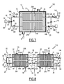
- a third unit 100 of transformation according to the invention is represented on the figure 7 .
- the third unit 100 includes a bypass tap 102 connecting the inlet section 42A of the first tube 26A to the outlet section of the second tube 26B.
- the bypass tap 102 is provided with a pump 104 with an adjustable flow rate. It is thus possible to derive a volume fraction of between 0% and 100% of the product to transform directly into the output section 26B, without passing through the enclosure 22. Such a configuration allows to deliberately degrade the character "piston" of the transformation module 12. This allows for example to determine what is the requirement in character "piston Of a given chemistry. As a result, it is possible to size the pilot or industrial reactor to just the necessary from a hydrodynamic point of view to minimize investment and proportional costs while ensuring high chemical performance.
- a fourth unit 110 according to the invention is represented on the figure 8 . Unlike the first unit 10, the fourth unit 110 has a plurality of modules 12C, 12D connected in series.
- this number may be greater than 2.
- the number of modules 12C, 12D is equal to 2.
- the output section 46A of the first tube 26A of the first module 12C is connected to the input section 42A of the first tube 26A of the second module 12D.
- the output section 46B of the second tube 26B of the second module 12D is connected to the input section 42B of the second tube 26B of the first module 12C.
- the second module 12D is provided with a connection 82 connecting the first tube 26A to the second tube 26B, of structure similar to that described above for the second unit 80.
- the connector 82 hydraulically connects the outlet section 46A of the first tube 26A of the second module 12D and the input section 42B of the second tube 26C of the second module 12D.
- a continuous fluidic path can be established for the product to be transformed between the injection assembly 14A, the first tube 26A of the first module 12C, the first tube 26A of the second module 12D, the connection fitting 82, the second tube 26B of the second module 12D, the second tube 26B of the first module 12C and the recovery assembly 16A.
- the residence time of the product to be transformed in the successive enclosures 22 is thus increased. Moreover, it is possible to subject various heat treatments to the product to be processed, for example by subjecting it to different temperatures in the successive enclosures 22.
- the fourth unit 110 comprises a plurality of auxiliary injection assemblies 90 as described above, respectively stitched on the connection fitting 82 and / or on one of the connection tubes between the modules 12C and 12D. formed respectively by the outlet pipe 46A of the first tube 26A of the first module 12C associated with the inlet pipe 42A of the first pipe 26A of the second module 12C or formed by the outlet pipe 46B of the second tube 26B of the second module 12D associated with the inlet pipe 42B of the second tube 26B of the first module 12C.
- temperature sensors 66 and detection 68 may be placed at various points on the connecting pipes or on the connection 82 to accurately study the conditions of the transformation.
- each tube 26A, 26B of each module 12 is illustrated by the distribution of the residence times as a function of the time represented on the figure 9 , for a color indicator injected at the input in the form of a concentration step.
- the number of perfectly stirred reactors J for different flow rates and the average residence time ⁇ i in each reactor are represented as a function of the flow rate on the figure 9 .
- the dispersion is minimal following the input injection of a product step. This dispersion is much lower than that observed for a linear tube of similar length.
- the number of equivalent reactors is at least greater than 20, or even greater than 100 when the flow rate decreases.
- the transformations are performed adiabatically.
- the tubes 26A, 26B are not necessarily immersed in a liquid but can be placed in a volume of gas.
- each transformation tube 26A, 26B is for example immersed in a fluid capable of being a thermal insulator with respect to the tube 26A, 26B.
- This fluid is for example a gas such as ambient air.
- the unit 10 is devoid of means for regulating the temperature in each tube 26A, 26B.
- the product to be converted circulating in each tube 26A, 26B evolves adiabatically, without heating or external cooling.
- the enclosure 22 is advantageously covered with the heat-insulating jacket 28 described above.
- the regulation assembly 18 includes means for heating the tube 26A, 26B without any heat transfer liquid 24.
- the thermal regulation assembly remains clean to heat the product present in the tube 26A, 26B over the entire periphery of the tube 26A, 26B.
- heating means are, for example, in-mass heating means such as a microwave source, or means for heating the tube, such as induction heating means, hot air heating means, means for heating, infra-red heating or other heating means.
- the thermal regulation assembly further comprises cooling means.
- the number of tubes 26A, 26B in the chamber is greater than 2.
- a valve calibrated at a predefined pressure advantageously greater than the atmospheric pressure is placed at the outlet of a helical tube.
- the preset pressure is for example chosen to be slightly higher, for example at least 5% higher than the saturated vapor pressure of the reaction medium circulating in the tube at the reaction temperature to which the reaction medium is subjected.
- the dimensions of the circulating light, and in particular the small diameter of the helical tube, guarantees a S / V ratio between the internal surface S delimited by the tube and the volume V of the circulating light between 400 m -1. and 4000 m -1 , advantageously between 500 m -1 and 3000 m -1 .
Priority Applications (2)
| Application Number | Priority Date | Filing Date | Title |
|---|---|---|---|
| EP10305767A EP2404666A1 (de) | 2010-07-09 | 2010-07-09 | Modul zur kontinuierlichen Umwandlung mindestens eines flüssigen Produkts, entsprechende Einheit und entsprechendes Verfahren |
| PCT/FR2011/050618 WO2011117540A1 (fr) | 2010-03-23 | 2011-03-23 | Module de transformation continue d'au moins un produit fluide, unité et procédé associés |
Applications Claiming Priority (1)
| Application Number | Priority Date | Filing Date | Title |
|---|---|---|---|
| EP10305767A EP2404666A1 (de) | 2010-07-09 | 2010-07-09 | Modul zur kontinuierlichen Umwandlung mindestens eines flüssigen Produkts, entsprechende Einheit und entsprechendes Verfahren |
Publications (1)
| Publication Number | Publication Date |
|---|---|
| EP2404666A1 true EP2404666A1 (de) | 2012-01-11 |
Family
ID=42751617
Family Applications (1)
| Application Number | Title | Priority Date | Filing Date |
|---|---|---|---|
| EP10305767A Withdrawn EP2404666A1 (de) | 2010-03-23 | 2010-07-09 | Modul zur kontinuierlichen Umwandlung mindestens eines flüssigen Produkts, entsprechende Einheit und entsprechendes Verfahren |
Country Status (1)
| Country | Link |
|---|---|
| EP (1) | EP2404666A1 (de) |
Cited By (8)
| Publication number | Priority date | Publication date | Assignee | Title |
|---|---|---|---|---|
| WO2015189228A1 (de) * | 2014-06-12 | 2015-12-17 | Hte Gmbh The High Throughput Experimentation Company | Kompakter katalysator-teststand und befüllen desselben |
| US9630163B2 (en) * | 2015-05-27 | 2017-04-25 | Commonwealth Scientific And Industrial Research Organisation | Production of metal-organic frameworks |
| EP3178549A1 (de) * | 2015-12-09 | 2017-06-14 | Blacktrace Holdings Limited | Rohrreaktor mit temperiereinheit und wärmetauschereinrichtungen |
| CN107638862A (zh) * | 2017-08-09 | 2018-01-30 | 凯莱英生命科学技术(天津)有限公司 | 连续盘管反应器、连续盘管反应装置及其在库尔提斯重排反应中的应用 |
| KR20180012179A (ko) * | 2015-05-27 | 2018-02-05 | 커먼웰쓰 사이언티픽 앤 인더스트리알 리서치 오거니제이션 | 금속-유기 구조체의 제조 |
| US20180305290A1 (en) * | 2014-02-17 | 2018-10-25 | Kumiai Chemical Industry Co., Ltd. | Method for continuously producing ketomalonic acid compound using flow reactor |
| US20190091645A1 (en) * | 2016-06-21 | 2019-03-28 | P2 Science, Inc. | Flow-through reactors for the continuous quenching of peroxide mixtures and methods comprising the same |
| CN115175888A (zh) * | 2019-12-19 | 2022-10-11 | 联邦科学和工业研究组织 | 卤代烷氧基乙烷的制备 |
Citations (5)
| Publication number | Priority date | Publication date | Assignee | Title |
|---|---|---|---|---|
| EP0240340A2 (de) * | 1986-04-03 | 1987-10-07 | WASTE TREATMENT PATENTS & RESEARCH N.V. | Verfahren und Reaktor zum Ausführen von gesteuerten chemischen Reaktionen |
| WO1992007226A1 (en) | 1990-10-16 | 1992-04-30 | Nederlandsche Organisatie Voor Toegepast-Natuurwetenschappelijk Onderzoek Tno | Spiral heat exchanger |
| WO2001036514A1 (en) * | 1999-11-18 | 2001-05-25 | Basf Corporation | Continuous process for the production of polyether polyols |
| FR2884443A1 (fr) * | 2005-04-18 | 2006-10-20 | Inst Francais Du Petrole | Reacteur de laboratoire pour l'etude de reactions en phase gaz et liquide |
| WO2009151322A1 (en) * | 2008-06-10 | 2009-12-17 | Nederlandse Organisatie Voor Toegepast-Natuurwetenschappelijk Onderzoek Tno | Process and apparatus for carrying out multi-phase reactions |
-
2010
- 2010-07-09 EP EP10305767A patent/EP2404666A1/de not_active Withdrawn
Patent Citations (5)
| Publication number | Priority date | Publication date | Assignee | Title |
|---|---|---|---|---|
| EP0240340A2 (de) * | 1986-04-03 | 1987-10-07 | WASTE TREATMENT PATENTS & RESEARCH N.V. | Verfahren und Reaktor zum Ausführen von gesteuerten chemischen Reaktionen |
| WO1992007226A1 (en) | 1990-10-16 | 1992-04-30 | Nederlandsche Organisatie Voor Toegepast-Natuurwetenschappelijk Onderzoek Tno | Spiral heat exchanger |
| WO2001036514A1 (en) * | 1999-11-18 | 2001-05-25 | Basf Corporation | Continuous process for the production of polyether polyols |
| FR2884443A1 (fr) * | 2005-04-18 | 2006-10-20 | Inst Francais Du Petrole | Reacteur de laboratoire pour l'etude de reactions en phase gaz et liquide |
| WO2009151322A1 (en) * | 2008-06-10 | 2009-12-17 | Nederlandse Organisatie Voor Toegepast-Natuurwetenschappelijk Onderzoek Tno | Process and apparatus for carrying out multi-phase reactions |
Non-Patent Citations (1)
| Title |
|---|
| NAPHON P ET AL: "A review of flow and heat transfer characteristics in curved tubes", RENEWABLE AND SUSTAINABLE ENERGY REVIEWS, ELSEVIERS SCIENCE, NEW YORK, NY, US LNKD- DOI:10.1016/J.RSER.2004.09.014, vol. 10, no. 5, 1 October 2006 (2006-10-01), pages 463 - 490, XP025173980, ISSN: 1364-0321, [retrieved on 20061001] * |
Cited By (14)
| Publication number | Priority date | Publication date | Assignee | Title |
|---|---|---|---|---|
| US20180305290A1 (en) * | 2014-02-17 | 2018-10-25 | Kumiai Chemical Industry Co., Ltd. | Method for continuously producing ketomalonic acid compound using flow reactor |
| WO2015189228A1 (de) * | 2014-06-12 | 2015-12-17 | Hte Gmbh The High Throughput Experimentation Company | Kompakter katalysator-teststand und befüllen desselben |
| US10525440B2 (en) | 2015-05-27 | 2020-01-07 | Commonwealth Scientific And Industrial Research Organisation | Production of metal-organic frameworks |
| KR20180012179A (ko) * | 2015-05-27 | 2018-02-05 | 커먼웰쓰 사이언티픽 앤 인더스트리알 리서치 오거니제이션 | 금속-유기 구조체의 제조 |
| US10010860B2 (en) * | 2015-05-27 | 2018-07-03 | Commonwealth Scientific And Industrial Research Organisation | Production of metal-organic frameworks |
| US10272412B2 (en) | 2015-05-27 | 2019-04-30 | Commonwealth Scientific And Industrial Research Organisation | Production of metal-organic frameworks |
| US9630163B2 (en) * | 2015-05-27 | 2017-04-25 | Commonwealth Scientific And Industrial Research Organisation | Production of metal-organic frameworks |
| US10906023B2 (en) | 2015-05-27 | 2021-02-02 | Commonwealth Scientific And Industrial Research Organisation | Production of metal-organic frameworks |
| EP3178549A1 (de) * | 2015-12-09 | 2017-06-14 | Blacktrace Holdings Limited | Rohrreaktor mit temperiereinheit und wärmetauschereinrichtungen |
| US20190091645A1 (en) * | 2016-06-21 | 2019-03-28 | P2 Science, Inc. | Flow-through reactors for the continuous quenching of peroxide mixtures and methods comprising the same |
| US10668446B2 (en) * | 2016-06-21 | 2020-06-02 | P2 Science, Inc. | Flow-through reactors for the continuous quenching of peroxide mixtures and methods comprising the same |
| CN107638862A (zh) * | 2017-08-09 | 2018-01-30 | 凯莱英生命科学技术(天津)有限公司 | 连续盘管反应器、连续盘管反应装置及其在库尔提斯重排反应中的应用 |
| CN115175888A (zh) * | 2019-12-19 | 2022-10-11 | 联邦科学和工业研究组织 | 卤代烷氧基乙烷的制备 |
| EP4077257A4 (de) * | 2019-12-19 | 2023-09-27 | Commonwealth Scientific and Industrial Research Organisation | Herstellung von halogeniertem alkoxyethan |
Similar Documents
| Publication | Publication Date | Title |
|---|---|---|
| EP2404666A1 (de) | Modul zur kontinuierlichen Umwandlung mindestens eines flüssigen Produkts, entsprechende Einheit und entsprechendes Verfahren | |
| Kuhn et al. | A pH-sensitive laser-induced fluorescence technique to monitor mass transfer in multiphase flows in microfluidic devices | |
| EP2332643B1 (de) | Kompakte Flüssigkeitsmischvorrichtung in einem Reaktor mit Abwärtsströmung | |
| Martinez Arias et al. | Continuous synthesis and in situ monitoring of biodiesel production in different microfluidic devices | |
| Trivedi et al. | Axial dispersion in laminar flow in helical coils | |
| Sun et al. | Fast synthesis of biodiesel at high throughput in microstructured reactors | |
| WO2008043922A2 (fr) | Procede et installation de determination d'au moins un parametre d'une transformation physique et/ou chimique, et procede de criblage correspondant | |
| Floyd et al. | Silicon micromixers with infrared detection for studies of liquid-phase reactions | |
| Liu et al. | Micro-distillation system for formaldehyde concentration detection | |
| Commenge et al. | Gas-phase residence time distribution in a falling-film microreactor | |
| FR3012143A1 (de) | ||
| FR2890578A1 (fr) | Dispositif d'ecoulement microfluidique permettant de determiner des parametres d'une transformation physique et/ ou chimique, et son utilisation | |
| WO2011117540A1 (fr) | Module de transformation continue d'au moins un produit fluide, unité et procédé associés | |
| Yusuf et al. | Fabrication of novel microreactors in-house and their performance analysis via continuous production of biodiesel | |
| US11279882B2 (en) | Hydrothermal liquefaction system | |
| Minnich et al. | Determination of the dispersion characteristics of miniaturized coiled reactors with fiber-optic Fourier transform mid-infrared spectroscopy | |
| CA2312520A1 (fr) | Methode et dispositif multi-reacteurs automatique d'evaluation de catalyseurs avec analyse en ligne sans separation liquide/gaz | |
| WO2015170034A1 (fr) | Dispositif d'injection, notamment pour injecter une charge d'hydrocarbures dans une unité de raffinage. | |
| Tan et al. | Rapid measurement of gas solubility in liquids using a membrane dispersion microcontactor | |
| Mongeon et al. | Liquid–Liquid Mass Transfer in an Oscillatory-Flow Mesoscale Coil Reactor without Baffles | |
| EP1279430B1 (de) | Vorrichtung zur Trennung der Phasen eines zweiphasengemisches und deren Anwendung zur Bestimmung der physikalischen und/oder chemischen Parameter dieses Gemisches | |
| Loll et al. | Zickzack packings for deaeration in rotating packed beds─ improved rotor design to counter bypass flows | |
| Yu et al. | Bubble Morphology Analysis and Pressure Drop of Gas–Liquid Two-Phase Flow inside a Quarto Static Mixer | |
| Chicoma et al. | In Line monitoring of VAc‐BuA emulsion polymerization reaction in a continuous pulsed sieve plate reactor using NIR spectroscopy | |
| Minnich et al. | Bridging the gap: A nested-pipe reactor for slow reactions in continuous flow chemical synthesis |
Legal Events
| Date | Code | Title | Description |
|---|---|---|---|
| AK | Designated contracting states |
Kind code of ref document: A1 Designated state(s): AL AT BE BG CH CY CZ DE DK EE ES FI FR GB GR HR HU IE IS IT LI LT LU LV MC MK MT NL NO PL PT RO SE SI SK SM TR |
|
| AX | Request for extension of the european patent |
Extension state: BA ME RS |
|
| PUAI | Public reference made under article 153(3) epc to a published international application that has entered the european phase |
Free format text: ORIGINAL CODE: 0009012 |
|
| 17P | Request for examination filed |
Effective date: 20120116 |
|
| STAA | Information on the status of an ep patent application or granted ep patent |
Free format text: STATUS: THE APPLICATION IS DEEMED TO BE WITHDRAWN |
|
| 18D | Application deemed to be withdrawn |
Effective date: 20120727 |