EP2404058B1 - Yaw system for a windmill - Google Patents
Yaw system for a windmill Download PDFInfo
- Publication number
- EP2404058B1 EP2404058B1 EP10708968.2A EP10708968A EP2404058B1 EP 2404058 B1 EP2404058 B1 EP 2404058B1 EP 10708968 A EP10708968 A EP 10708968A EP 2404058 B1 EP2404058 B1 EP 2404058B1
- Authority
- EP
- European Patent Office
- Prior art keywords
- yaw
- nacelle
- turbine
- motor
- torque
- Prior art date
- Legal status (The legal status is an assumption and is not a legal conclusion. Google has not performed a legal analysis and makes no representation as to the accuracy of the status listed.)
- Active
Links
Images


Classifications
-
- F—MECHANICAL ENGINEERING; LIGHTING; HEATING; WEAPONS; BLASTING
- F03—MACHINES OR ENGINES FOR LIQUIDS; WIND, SPRING, OR WEIGHT MOTORS; PRODUCING MECHANICAL POWER OR A REACTIVE PROPULSIVE THRUST, NOT OTHERWISE PROVIDED FOR
- F03D—WIND MOTORS
- F03D7/00—Controlling wind motors
- F03D7/02—Controlling wind motors the wind motors having rotation axis substantially parallel to the air flow entering the rotor
- F03D7/022—Adjusting aerodynamic properties of the blades
-
- F—MECHANICAL ENGINEERING; LIGHTING; HEATING; WEAPONS; BLASTING
- F03—MACHINES OR ENGINES FOR LIQUIDS; WIND, SPRING, OR WEIGHT MOTORS; PRODUCING MECHANICAL POWER OR A REACTIVE PROPULSIVE THRUST, NOT OTHERWISE PROVIDED FOR
- F03D—WIND MOTORS
- F03D7/00—Controlling wind motors
- F03D7/02—Controlling wind motors the wind motors having rotation axis substantially parallel to the air flow entering the rotor
- F03D7/0204—Controlling wind motors the wind motors having rotation axis substantially parallel to the air flow entering the rotor for orientation in relation to wind direction
-
- F—MECHANICAL ENGINEERING; LIGHTING; HEATING; WEAPONS; BLASTING
- F03—MACHINES OR ENGINES FOR LIQUIDS; WIND, SPRING, OR WEIGHT MOTORS; PRODUCING MECHANICAL POWER OR A REACTIVE PROPULSIVE THRUST, NOT OTHERWISE PROVIDED FOR
- F03D—WIND MOTORS
- F03D1/00—Wind motors with rotation axis substantially parallel to the air flow entering the rotor
- F03D1/101—Nacelles
- F03D1/181—Nacelles characterised by the connection to the tower, e.g. yaw systems
-
- F—MECHANICAL ENGINEERING; LIGHTING; HEATING; WEAPONS; BLASTING
- F03—MACHINES OR ENGINES FOR LIQUIDS; WIND, SPRING, OR WEIGHT MOTORS; PRODUCING MECHANICAL POWER OR A REACTIVE PROPULSIVE THRUST, NOT OTHERWISE PROVIDED FOR
- F03D—WIND MOTORS
- F03D7/00—Controlling wind motors
- F03D7/02—Controlling wind motors the wind motors having rotation axis substantially parallel to the air flow entering the rotor
- F03D7/022—Adjusting aerodynamic properties of the blades
- F03D7/0224—Adjusting blade pitch
-
- F—MECHANICAL ENGINEERING; LIGHTING; HEATING; WEAPONS; BLASTING
- F03—MACHINES OR ENGINES FOR LIQUIDS; WIND, SPRING, OR WEIGHT MOTORS; PRODUCING MECHANICAL POWER OR A REACTIVE PROPULSIVE THRUST, NOT OTHERWISE PROVIDED FOR
- F03D—WIND MOTORS
- F03D7/00—Controlling wind motors
- F03D7/02—Controlling wind motors the wind motors having rotation axis substantially parallel to the air flow entering the rotor
- F03D7/04—Automatic control; Regulation
-
- F—MECHANICAL ENGINEERING; LIGHTING; HEATING; WEAPONS; BLASTING
- F05—INDEXING SCHEMES RELATING TO ENGINES OR PUMPS IN VARIOUS SUBCLASSES OF CLASSES F01-F04
- F05B—INDEXING SCHEME RELATING TO WIND, SPRING, WEIGHT, INERTIA OR LIKE MOTORS, TO MACHINES OR ENGINES FOR LIQUIDS COVERED BY SUBCLASSES F03B, F03D AND F03G
- F05B2260/00—Function
- F05B2260/90—Braking
- F05B2260/903—Braking using electrical or magnetic forces
-
- F—MECHANICAL ENGINEERING; LIGHTING; HEATING; WEAPONS; BLASTING
- F05—INDEXING SCHEMES RELATING TO ENGINES OR PUMPS IN VARIOUS SUBCLASSES OF CLASSES F01-F04
- F05B—INDEXING SCHEME RELATING TO WIND, SPRING, WEIGHT, INERTIA OR LIKE MOTORS, TO MACHINES OR ENGINES FOR LIQUIDS COVERED BY SUBCLASSES F03B, F03D AND F03G
- F05B2270/00—Control
- F05B2270/30—Control parameters, e.g. input parameters
- F05B2270/329—Azimuth or yaw angle
-
- F—MECHANICAL ENGINEERING; LIGHTING; HEATING; WEAPONS; BLASTING
- F05—INDEXING SCHEMES RELATING TO ENGINES OR PUMPS IN VARIOUS SUBCLASSES OF CLASSES F01-F04
- F05B—INDEXING SCHEME RELATING TO WIND, SPRING, WEIGHT, INERTIA OR LIKE MOTORS, TO MACHINES OR ENGINES FOR LIQUIDS COVERED BY SUBCLASSES F03B, F03D AND F03G
- F05B2270/00—Control
- F05B2270/60—Control system actuates through
- F05B2270/602—Control system actuates through electrical actuators
-
- Y—GENERAL TAGGING OF NEW TECHNOLOGICAL DEVELOPMENTS; GENERAL TAGGING OF CROSS-SECTIONAL TECHNOLOGIES SPANNING OVER SEVERAL SECTIONS OF THE IPC; TECHNICAL SUBJECTS COVERED BY FORMER USPC CROSS-REFERENCE ART COLLECTIONS [XRACs] AND DIGESTS
- Y02—TECHNOLOGIES OR APPLICATIONS FOR MITIGATION OR ADAPTATION AGAINST CLIMATE CHANGE
- Y02E—REDUCTION OF GREENHOUSE GAS [GHG] EMISSIONS, RELATED TO ENERGY GENERATION, TRANSMISSION OR DISTRIBUTION
- Y02E10/00—Energy generation through renewable energy sources
- Y02E10/70—Wind energy
- Y02E10/72—Wind turbines with rotation axis in wind direction
Definitions
- the present invention relates to generally a yaw system for a windmill, the windmill comprising a tower and a nacelle, the tower and the nacelle being joined by the yaw system and the yaw system further comprising a bearing fixed to the tower, on which bearing the nacelle rests and slides in a yawing movement, and at least one yaw motor arranged to allow the nacelle to perform a rotary motion along the bearing.
- the invention also relates to a method for controlling the yaw of a windmill, comprising the steps of determining a set point for the windmill, determining a yaw error based on the set point and a current alignment of the windmill, determining a size and direction of a torque based at least on the yaw error, and applying the torque to at least one yaw motor of a yaw system for turning the turbine.
- the applied yaw brakes will have to be loosened, and the start of such a moving operation can be difficult to achieve without causing a sudden starts or undesired vibrations.
- One common way of avoiding this is to keep using at least one of the brakes also during use of the yaw motor, in order to provide for a more controlled motion. This requires a power of the yaw motor that is greater than that otherwise needed for the motion in itself, had no brake been applied.
- DE 19 920 504 A1 further discloses the use of yaw drive motors in braking mode to keep a nacelle in stand still position. There is therefore a need for a more reliable yaw system that can estimate the loads and reduce the wear and tear to the windmill and that can also increase the power generated from the windmill.
- One object of the present invention is to eliminate or at least to minimise the problems described above. This is achieved through a yaw system for a windmill according to claim 1, wherein the yaw system further comprises control means for continuously operating the at least one yaw motor in such a way that the yaw motor strives to manoeuvre the nacelle according to a setpoint. Thereby, the operation of the windmill can be optimised and damages to the windmill from the force of the wind minimised.
- the yaw motor is arranged to provide both negative and positive torque (-M, +M), respectively.
- the turbine can be turned clockwise as well as anti clockwise using the same yaw system, and the yaw error can be minimised in a convenient and reliable manner.
- control means is arranged to achieve four quadrant control.
- a convenient and versatile control over the yaw system can be achieved and the yaw system made to be soft rather than stiff, thereby avoiding creating unnecessary stresses in the windmill itself or the yaw system.
- At least one yaw motor property from the four quadrant control is arranged to use the control means to control a pitch angle of at least one turbine blade of the turbine.
- the load on the turbine can be decreased and the possible energy yield from the generator increased.
- the pitch angle of the blades can be controlled individually, thereby enabling pitch angle adjustments corresponding to an optimal position of the blades with respect to the surrounding conditions.
- control means is arranged to detect unbalances to the turbine using at least the at least one yaw motor property. Thereby, any factors contributing to increasing the load or decreasing the energy output that is available from the system can be detected, and the system can be used to minimise these unbalances in order to further optimize the operation of the windmill.
- control means is further arranged to determine wind conditions such as wind speed, wind direction, wind shear or upflow, based at least on the yaw motor property.
- wind conditions such as wind speed, wind direction, wind shear or upflow
- control system is arranged to react by activating an alarm function if the detected unbalances exceed a predetermined value.
- the windmill can be shut down if the risk for damages due to unbalanced turbine is too large, or an alarm signal can be generated, signalling that maintenance is needed.
- Fig. 1 shows a windmill 1 with a yaw system 5 according to a preferred embodiment of the invention, where a tower 2 that is firmly mounted on the ground is joined to a nacelle 3 that houses an electrical power generator 7 (not shown).
- the power generator 7 comprises a generator with a shaft 71 that can be made to rotate around an axis A along the length of the nacelle 3, and onto this shaft 71 is mounted a turbine 4 with a hub 42 where at least one, preferably two or three turbine blades 41, in turn are mounted.
- the wind interacting with the turbine blades 41 can cause a rotation of the turbine 4 and result in electrical power being generated by the generator 7 and transferred to a power grid or stored in a suitable storage means (not shown).
- turbine used herein is to be interpreted as a hub 42 including at least one blade 41 and designed to rotate around an axis in order to generate an electrical power at a power generator 7 or other suitable device for using the rotational energy thus created.
- the rotational movement itself is mainly effected through the influence of a wind.
- the nacelle 3 can rotate around an axis B that extends along the length of the tower 2, i.e. from the ground and substantially vertically upwards as indicated in Fig. 1 .
- the rotation is effected by a yaw system 5 that is placed at the join between the tower 2 and the nacelle 3, and comprises a yaw bearing 51 b that is mounted on the tower 2 and arranged to interact with a bearing 51 a mounted on the nacelle 3.
- a sliding track 54 can also be provided at the yaw system 5 for further enabling the yaw motion.
- the sliding motion is created by at least one, but preferably 2-6 yaw motors 52, mounted on the nacelle 3 and arranged to interact with the yaw bearing 51 of the tower 2 in such a way that the sliding motion can be controlled.
- the at least one yaw motor 52 can act with a torque M that is smaller than or equal to a maximum torque M max .
- At least one yaw sensor 53 is mounted adjacent to the yaw system and is arranged to detect at least one feature, such as yaw position, angular velocity or acceleration, of a point on or adjacent to the yaw system.
- wind sensor means 6 that can be mounted on the nacelle 3, and that can detect features of the wind at the site of the windmill 1.
- a control system 8 placed inside the nacelle 3 is arranged to control the yaw system and other features of the operation of the windmill 1.
- Fig. 2 shows a cross-sectional perspective view of a part of the yaw system 5, with a yaw motor 52 mounted on the nacelle 3 and cooperating with the yaw bearing 51 in such a way that one section 51 b, that is mounted onto the tower 2, and another section 51a, that is mounted on a main frame and yaw motor 52 itself, can move in relation to each other, thereby creating the sliding motion of the nacelle 3 with respect to the tower 2.
- Fig. 3 the operation of the yaw system 5 is shown, whereby the control system 8 is arranged to receive input data from the wind sensor 6 with regards to the strength and direction W of an oncoming wind, and for the yaw sensor 53 with regards to the position, velocity and/or acceleration of a point that is affected by the operation of the yaw system 5, as mentioned above.
- the point can be placed on the circumference of the outer bearing 51 a, adjacent to a yaw motor 52, or on another suitable location such as inside the nacelle 3.
- the control system 8 also receives input data from the yaw motor 52 itself regarding the current motor torque M and other operating conditions, and gives instructions to the yaw motor 52 as output data.
- the output data can comprise an instruction regarding the magnitude of the desired motor torque M and the desired direction of movement of the nacelle 3 with respect to the tower 2.
- the optimal operation of the windmill 1 is achieved as the nacelle 3 with the turbine 4 are turned to point in a specific direction, herein referred to as the yaw setpoint.
- This direction can be determined by detecting the wind direction or other factors that are deemed to be relevant.
- An example of a yaw setpoint can be to achieve an orientation of the plane of the turbine 4, i.e. the plane comprising the turbine blades 41, perpendicular to the wind direction.
- the yaw setpoint may also be a value corresponding not to a specific alignment but to other properties of the yaw system, such as for instance the yaw speed, the yaw acceleration or the yaw torque.
- the yaw system 5 continuously applies a torque M at the at least one yaw motor 52 in order to minimise this yaw error and turn the nacelle 3 and turbine 4 towards the yaw setpoint.
- the yaw setpoint can be continuously monitored and re-calculated at any given time, in order to keep the setpoint up to date as the wind direction or wind strength changes, and the system 5 continuously strives to minimise the yaw error and reach the yaw setpoint.
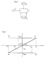
- Fig. 4 shows a diagram of the motor torque M of the yaw motor or yaw motors 52 with respect to the angular velocity V of the nacelle 3, according to a method of four quadrant control.
- the torque M can be positive or negative, i.e. be directed in the counter clockwise or clockwise direction, respectively, depending on the direction of movement needed in order to align the turbine 4 with the wind.
- An example of the desired position at the setpoint, when the direction D of the hub 42 is aligned with that of the wind W, is shown schematically in Fig. 5a .
- the actual setpoint may in some cases be another than that where the turbine 4 is perpendicular to the wind.
- Fig. 5a-5c indicate different positions of the nacelle 3 of the windmill 1 with respect to a direction W of an oncoming wind. It is assumed that the chosen setpoint is when the direction D of the turbine 4 and the nacelle 3 is along the line W of the wind direction.
- a positive torque M a can be applied to the yaw system, corresponding to an angular yaw velocity of V a of the nacelle 3 shown in the first quadrant, Q1, of the diagram of Fig. 4 . If the torque is increased towards a maximum of M max , the resulting angular velocity is also increased, resulting in an angular velocity of V b .
- the absolute value of the velocity can depend on factors such as the force of the wind or the pitch angle of the blades 41, as well as the direction of the nacelle 3.
- a collective pitch control might be used for altering the pitch of more than one blade 41 collectively, while an individual pitch control is used to alter the pitch of only one blade 41.
- Collective pitch control is mainly used in order to alter the amount of energy captured from the wind, while individual pitch control is used to provide yaw torque or counteract an unbalance in the turbine 4, among others.
- a negative torque - M a can be applied, resulting in an angular yaw velocity -V ⁇ of the nacelle 3, and an increase of the negative torque towards a maximum value, -M max , would result in an angular yaw velocity -V ⁇ of the nacelle 3. This is shown in the third quadrant, Q3, of the diagram of Fig. 4 .
- the maximum torque M max or -M max can be applied and try to push the nacelle 3 towards the wind.
- the resulting motion is directed in the opposite direction due to the surrounding conditions.
- the result can be an increasing in the yaw error, and is displayed as a velocity -V ⁇ in the fourth quadrant Q4 of the diagram or the velocity V ⁇ in the second quadrant Q2, respectively.
- the yaw system 5 thereby allows the nacelle 3 to divert from the yaw setpoint whenever external yaw wise torque on the nacelle 3 exceeds an allowed yaw motor capacity, i.e. when the maximum torque M max or -M max , respectively is applied. This yaw motion away from the yaw setpoint is thereby counteracted by a yaw motor torque M.
- the control system 8 controls the yaw system, as has previously been described, with the yaw motor or yaw motors 52 in order to reach the desired direction shown by Fig. 5a , and the yaw motors 52 are used continuously in order to strive towards and/or maintain this position.
- the wind sensor 6 monitors the direction of the wind and communicates this to the control system, which also receives input from the yaw sensor 53 that detects the current position of the nacelle 3 and the rotational speed (direction and velocity) and/or corresponding acceleration of the nacelle 3. Using these inputs, the control system 8 decides which torque M is suitable at that particular time, and communicates this to the yaw motor or yaw motors 52.
- the yaw process is continuous, and the control system 8 alters the torque M as needed in order to rotate the nacelle 3 and minimize the yaw error. From the yaw motor 52, data regarding the torque M and other relevant properties at any given time is continuously given as feedback to the control system 8.
- the control system 8 detects this by processing the data from the wind sensor 6 and the yaw sensor 53, and determines the yaw error itself along with the rotational direction in which a movement is desired in order to reduce the yaw error.
- this desired rotational direction is clockwise, and a torque -M in this direction is applied in order to create a rotation.
- the actual movement can be closely observed by monitoring the present position of the nacelle 3 as well as the speed in which it rotates and the acceleration of the rotation.
- the torque can be adapted in order to create a controlled and efficient movement, to add extra force if needed or to decrease the torque and thereby act as a brake on the rotation as the desired position is reached in order to avoid an excessive movement past the alignment of the directions D, W and cause the need of a new correction from the opposite direction.
- only the direction required for rotating the nacelle 3 in order to reach the setpoint is calculated and not the magnitude of the total yaw error.
- the yaw motor or motors 52 are used to maintain this position by using an appropriate torque M in the necessary direction in order to compensate for changes in the conditions affecting the windmill 1, such as the direction and strength of the wind, that would otherwise push the nacelle 3 away and create an undesired yaw wise rotation away from the position.
- the optimal position can be maintained once it has been reached and the power generated from the windmill can be maximised.
- the maximum torque M max or -M max is not sufficient to rotate the nacelle 3 in the desired direction, but by continuously applying this torque the windmill can be kept steady in as good a position as possible, i.e. as close to the desired position of Fig. 5a as can be achieved.
- the system can detect the amount of force that the turbine blades 41 and the rest of the windmill 1 are subjected to. If this force is large enough to cause damages to the system, this can be used as a reason for turning off the power generation system, thereby reaching normal shut down procedures (cut out), or for altering the pitch of the turbine blades 41 in order to lessen this force and enable the yaw system to rotate the nacelle 3 towards a better position.
- the present invention it is possible to operate the turbine 4 in higher wind speeds if the loads are low enough, and the decision to shut down the windmill 1 if necessary can be based on a combination of the detected wind speed and the state of the yaw system 5, mainly the motor torque M applied by the yaw motors 52.
- brakes used with the yaw system 5 can be kept for emergencies or unusual circumstances, and since the wear or damages on the brakes can be kept to a minimum, the need for repair is substantially lower than with conventional systems. Also, since the brakes are not worn down through ordinary use, the reliability of the braking system is increased.
- the properties of the yaw motor can be used to detect unbalances in the turbine 4. These unbalances can for instance be due to incorrect pitch of an individual turbine blade 41, damages to the blades 41 from excessive loads on the windmill 1 or from lightning strikes or other unexpected events, or from the formation of ice on the turbine blades 41 during winter time. If the unbalances are small, they can be corrected by altering the individual pitch of a single blade 41, but if the unbalances are large enough, correcting them might not be possible and there might arise a risk for serious damage to the windmill 1 itself.
- an alarm function can be initialised; taking control over the operation of the windmill 1 an initialising procedures to limit the possible damages.
- an alarm signal can be emitted in order to signal that maintenance is required, and the turbine 4 can be shut down completely or be kept operating at a lower speed, as is deemed suitable at the time, while waiting for a maintenance crew to arrive.
- the invention is not limited by the preferred embodiments described above, but can be varied within the scope of the appended claims, as will be readily understood by the person skilled in the art.
- the components described above such as the control system, sensor means, etc. can be placed at different locations at the windmill and can communicate with each other by any suitable means.
- the yaw sensor can also be integrated with the yaw motor or motors and the internal processes of the control system can differ from those described above.
- Yaw motors can be provided on the tower as well as on the nacelle, and the method for establishing a yaw setpoint can differ from that described with reference to the preferred embodiments.
Landscapes
- Engineering & Computer Science (AREA)
- Life Sciences & Earth Sciences (AREA)
- Sustainable Development (AREA)
- Sustainable Energy (AREA)
- Chemical & Material Sciences (AREA)
- Combustion & Propulsion (AREA)
- Mechanical Engineering (AREA)
- General Engineering & Computer Science (AREA)
- Physics & Mathematics (AREA)
- Fluid Mechanics (AREA)
- Wind Motors (AREA)
Description
- The present invention relates to generally a yaw system for a windmill, the windmill comprising a tower and a nacelle, the tower and the nacelle being joined by the yaw system and the yaw system further comprising a bearing fixed to the tower, on which bearing the nacelle rests and slides in a yawing movement, and at least one yaw motor arranged to allow the nacelle to perform a rotary motion along the bearing. The invention also relates to a method for controlling the yaw of a windmill, comprising the steps of determining a set point for the windmill, determining a yaw error based on the set point and a current alignment of the windmill, determining a size and direction of a torque based at least on the yaw error, and applying the torque to at least one yaw motor of a yaw system for turning the turbine.
- When using a windmill to generate electrical energy, it is in most cases desired to position the turbine perpendicular to the wind direction, or as close to a perpendicular position as possible. If the direction of the wind changes in such a way that the turbine is no longer perpendicular or close thereto, but rather parallel to the wind direction, a significant amount of energy is lost since the ability of the wind to cause a rotation of the blades is decreased. Also, an unsuitable wind direction causes an undesired increase of the load on the windmill and this can result in increased wear and tear, as well as an increased risk of serious damages to the components of the windmill.
- It is previously known to attempt a solution to this problem, such as that shown by
EP 1 571 334 (Gamesa Eolica - In order to use the yaw motor, the applied yaw brakes will have to be loosened, and the start of such a moving operation can be difficult to achieve without causing a sudden starts or undesired vibrations. One common way of avoiding this is to keep using at least one of the brakes also during use of the yaw motor, in order to provide for a more controlled motion. This requires a power of the yaw motor that is greater than that otherwise needed for the motion in itself, had no brake been applied.
- Also, since the yaw system is designed to keep the nacelle fixed (stiff) in a position until a large enough yaw error is detected, all external loads are carried by the yaw brakes and the overall structure. The size of these loads is often unknown and this fact, together with the changes that occur in the loads as the strength of the wind rapidly changes, can lead to damages to the turbine and the windmill and especially to the yaw brakes as the loads are transferred to stresses in the yaw system material.
- Similar systems are also shown by
US7,436,083 (Shibata et al. ) and byJP 2006-281655 DE 19 920 504 A1 further discloses the use of yaw drive motors in braking mode to keep a nacelle in stand still position. There is therefore a need for a more reliable yaw system that can estimate the loads and reduce the wear and tear to the windmill and that can also increase the power generated from the windmill. - One object of the present invention is to eliminate or at least to minimise the problems described above. This is achieved through a yaw system for a windmill according to
claim 1, wherein the yaw system further comprises control means for continuously operating the at least one yaw motor in such a way that the yaw motor strives to manoeuvre the nacelle according to a setpoint. Thereby, the operation of the windmill can be optimised and damages to the windmill from the force of the wind minimised. - According to an aspect of the invention, the yaw motor is arranged to provide both negative and positive torque (-M, +M), respectively. Thereby, the turbine can be turned clockwise as well as anti clockwise using the same yaw system, and the yaw error can be minimised in a convenient and reliable manner.
- According to the invention, the control means is arranged to achieve four quadrant control. Thereby, a convenient and versatile control over the yaw system can be achieved and the yaw system made to be soft rather than stiff, thereby avoiding creating unnecessary stresses in the windmill itself or the yaw system.
- According to yet another aspect of the invention, at least one yaw motor property from the four quadrant control is arranged to use the control means to control a pitch angle of at least one turbine blade of the turbine. Thereby, the load on the turbine can be decreased and the possible energy yield from the generator increased. If more than one turbine blade is used with the windmill, the pitch angle of the blades can be controlled individually, thereby enabling pitch angle adjustments corresponding to an optimal position of the blades with respect to the surrounding conditions.
- According to a further aspect of the invention, the control means is arranged to detect unbalances to the turbine using at least the at least one yaw motor property. Thereby, any factors contributing to increasing the load or decreasing the energy output that is available from the system can be detected, and the system can be used to minimise these unbalances in order to further optimize the operation of the windmill.
- According to another aspect of the invention, the control means is further arranged to determine wind conditions such as wind speed, wind direction, wind shear or upflow, based at least on the yaw motor property. Thereby, the yaw system can be used for determining the surrounding conditions in an easy and reliable way.
- According to a further aspect of the invention, the control system is arranged to react by activating an alarm function if the detected unbalances exceed a predetermined value. Thereby, the windmill can be shut down if the risk for damages due to unbalanced turbine is too large, or an alarm signal can be generated, signalling that maintenance is needed.
- The invention will now be described in more detail with reference to the appended drawings, wherein:
-
Fig. 1 shows a perspective view of a windmill comprising a yaw system according to a preferred embodiment of the invention, -
Fig. 2 shows a cross-sectional perspective view of a section of the yaw system ofFig. 1 , -
Fig. 3 shows a schematic view of the operation of the yaw system according toFig. 1 and 2 , -
Fig. 4 shows a diagram of the motor torque M of the yaw motors of the yaw system with respect to the angular velocity V of the turbine blades of the windmill, -
Fig. 5a shows a schematic view from above of a desired position of an upwind windmill with respect to the direction of the wind, -
Fig. 5b shows a schematic view from above of a position of an upwind windmill needing correction in the clockwise direction, and -
Fig. 5c shows a schematic view from above of a position of an upwind windmill needing correction in the counter clockwise direction. -
Fig. 1 shows awindmill 1 with ayaw system 5 according to a preferred embodiment of the invention, where atower 2 that is firmly mounted on the ground is joined to anacelle 3 that houses an electrical power generator 7 (not shown). The power generator 7 comprises a generator with ashaft 71 that can be made to rotate around an axis A along the length of thenacelle 3, and onto thisshaft 71 is mounted aturbine 4 with ahub 42 where at least one, preferably two or threeturbine blades 41, in turn are mounted. When thenacelle 3 is adjusted so that theturbine 4 faces the approximate direction of an oncoming wind, the wind interacting with theturbine blades 41 can cause a rotation of theturbine 4 and result in electrical power being generated by the generator 7 and transferred to a power grid or stored in a suitable storage means (not shown). - The term turbine used herein is to be interpreted as a
hub 42 including at least oneblade 41 and designed to rotate around an axis in order to generate an electrical power at a power generator 7 or other suitable device for using the rotational energy thus created. The rotational movement itself is mainly effected through the influence of a wind. - In order for the direction of the
turbine 4 to be adjusted, thenacelle 3 can rotate around an axis B that extends along the length of thetower 2, i.e. from the ground and substantially vertically upwards as indicated inFig. 1 . The rotation is effected by ayaw system 5 that is placed at the join between thetower 2 and thenacelle 3, and comprises a yaw bearing 51 b that is mounted on thetower 2 and arranged to interact with abearing 51 a mounted on thenacelle 3. As a result, a sliding rotary motion is made possible, where thenacelle 3 can turn around the axis B. A slidingtrack 54 can also be provided at theyaw system 5 for further enabling the yaw motion. - The sliding motion is created by at least one, but preferably 2-6
yaw motors 52, mounted on thenacelle 3 and arranged to interact with the yaw bearing 51 of thetower 2 in such a way that the sliding motion can be controlled. The at least oneyaw motor 52 can act with a torque M that is smaller than or equal to a maximum torque Mmax. At least oneyaw sensor 53 is mounted adjacent to the yaw system and is arranged to detect at least one feature, such as yaw position, angular velocity or acceleration, of a point on or adjacent to the yaw system. - Also provided are wind sensor means 6 that can be mounted on the
nacelle 3, and that can detect features of the wind at the site of thewindmill 1. Acontrol system 8 placed inside thenacelle 3 is arranged to control the yaw system and other features of the operation of thewindmill 1. -
Fig. 2 shows a cross-sectional perspective view of a part of theyaw system 5, with ayaw motor 52 mounted on thenacelle 3 and cooperating with the yaw bearing 51 in such a way that onesection 51 b, that is mounted onto thetower 2, and anothersection 51a, that is mounted on a main frame andyaw motor 52 itself, can move in relation to each other, thereby creating the sliding motion of thenacelle 3 with respect to thetower 2. - In
Fig. 3 , the operation of theyaw system 5 is shown, whereby thecontrol system 8 is arranged to receive input data from thewind sensor 6 with regards to the strength and direction W of an oncoming wind, and for theyaw sensor 53 with regards to the position, velocity and/or acceleration of a point that is affected by the operation of theyaw system 5, as mentioned above. The point can be placed on the circumference of theouter bearing 51 a, adjacent to ayaw motor 52, or on another suitable location such as inside thenacelle 3. Thecontrol system 8 also receives input data from theyaw motor 52 itself regarding the current motor torque M and other operating conditions, and gives instructions to theyaw motor 52 as output data. The output data can comprise an instruction regarding the magnitude of the desired motor torque M and the desired direction of movement of thenacelle 3 with respect to thetower 2. - The optimal operation of the
windmill 1 is achieved as thenacelle 3 with theturbine 4 are turned to point in a specific direction, herein referred to as the yaw setpoint. This direction can be determined by detecting the wind direction or other factors that are deemed to be relevant. An example of a yaw setpoint can be to achieve an orientation of the plane of theturbine 4, i.e. the plane comprising theturbine blades 41, perpendicular to the wind direction. The yaw setpoint may also be a value corresponding not to a specific alignment but to other properties of the yaw system, such as for instance the yaw speed, the yaw acceleration or the yaw torque. - After deciding upon the yaw setpoint, the actual direction of the
turbine 4 is compared with the setpoint and the difference is determined as the yaw error. Theyaw system 5 continuously applies a torque M at the at least oneyaw motor 52 in order to minimise this yaw error and turn thenacelle 3 andturbine 4 towards the yaw setpoint. The yaw setpoint can be continuously monitored and re-calculated at any given time, in order to keep the setpoint up to date as the wind direction or wind strength changes, and thesystem 5 continuously strives to minimise the yaw error and reach the yaw setpoint. -
Fig. 4 shows a diagram of the motor torque M of the yaw motor oryaw motors 52 with respect to the angular velocity V of thenacelle 3, according to a method of four quadrant control. The torque M can be positive or negative, i.e. be directed in the counter clockwise or clockwise direction, respectively, depending on the direction of movement needed in order to align theturbine 4 with the wind. An example of the desired position at the setpoint, when the direction D of thehub 42 is aligned with that of the wind W, is shown schematically inFig. 5a . The actual setpoint may in some cases be another than that where theturbine 4 is perpendicular to the wind. -
Fig. 5a-5c indicate different positions of thenacelle 3 of thewindmill 1 with respect to a direction W of an oncoming wind. It is assumed that the chosen setpoint is when the direction D of theturbine 4 and thenacelle 3 is along the line W of the wind direction. - If movement in a counter clockwise direction is required, as indicated by
Fig. 5c where a rotation in this direction is required in order to face the wind W, a positive torque Ma can be applied to the yaw system, corresponding to an angular yaw velocity of Va of thenacelle 3 shown in the first quadrant, Q1, of the diagram ofFig. 4 . If the torque is increased towards a maximum of Mmax, the resulting angular velocity is also increased, resulting in an angular velocity of Vb. The absolute value of the velocity can depend on factors such as the force of the wind or the pitch angle of theblades 41, as well as the direction of thenacelle 3. - When altering the pitch angle of the
turbine blades 41, a collective pitch control might be used for altering the pitch of more than oneblade 41 collectively, while an individual pitch control is used to alter the pitch of only oneblade 41. Collective pitch control is mainly used in order to alter the amount of energy captured from the wind, while individual pitch control is used to provide yaw torque or counteract an unbalance in theturbine 4, among others. By using an offset, i.e. an individual pitch angle alteration, this unbalance can be minimised, as is described further below. - If movement in a clockwise direction is required, as indicated by
Fig. 5b where a rotation in this direction is required in order to face the wind W, a negative torque - Ma can be applied, resulting in an angular yaw velocity -Vα of thenacelle 3, and an increase of the negative torque towards a maximum value, -Mmax, would result in an angular yaw velocity -Vβ of thenacelle 3. This is shown in the third quadrant, Q3, of the diagram ofFig. 4 . The absolute value |V| of the velocity still depends on various factors, as well as the direction of thehub 42, and as a consequence of this, |Va| is generally not equal to |-Vα|, and |Vb| is generally not equal to |Vβ|. - Under some conditions, for instance in very strong wind, a torque larger than |Mmax| would be required for rotating the
nacelle 3. In these cases, the maximum torque Mmax or -Mmax, respectively, can be applied and try to push thenacelle 3 towards the wind. The resulting motion, however, is directed in the opposite direction due to the surrounding conditions. Thus, the result can be an increasing in the yaw error, and is displayed as a velocity -Vγ in the fourth quadrant Q4 of the diagram or the velocity Vδ in the second quadrant Q2, respectively. Theyaw system 5 thereby allows thenacelle 3 to divert from the yaw setpoint whenever external yaw wise torque on thenacelle 3 exceeds an allowed yaw motor capacity, i.e. when the maximum torque Mmax or -Mmax, respectively is applied. This yaw motion away from the yaw setpoint is thereby counteracted by a yaw motor torque M. - As the
nacelle 3 is pushed away from the desired direction, the force on theblades 41 is decreased, since the change in direction also changes the angle of attack of theblades 41 with respect to the direction W. Thus, a position is reached where the force of the wind and the maximum torque Mmax are balanced and where thenacelle 3 can be kept steady until the wind changes. The torque Mmax is in this operation used to counteract the deviation from the setpoint and continue to strive towards the setpoint. During such operation, the loads on the system from the wind are smaller than would be the case if a stiff yaw system were used, since the yaw system now being soft and being able to yaw from the wind if the force of the oncoming wind is very strong actually protects thewindmill 1 from excessive loads that would otherwise cause stresses or damages to theyaw system 5 or theturbine 4. - These operations, when the rotation of the
nacelle 3 is to be found in the quadrants Q2 or Q4, theyaw motors 52 are actually working as generators. This means that operation in Q2 and Q4 generates power. This power can either be dissipated in resistors, stored in an accumulator, or entered back into the grid or power supply that normally powers the yaw motors. As operation in Q2 and Q4 dissipates power, the yaw system is, from a mechanical point of view, working as a damper. This damper effect is favorable as the magnitudes of motion and loads are decreased. - In extreme wind speeds above a predetermined level or under other extraordinary conditions, the motor operation in Q1 and Q3 is stopped by the
control system 8. The desired speed of the nacelle yaw rotation is zero, and under these conditions, operation in Q2 and Q4 is allowed only. The result of this mode of operation is that thenacelle 3 will find a yaw position where external yaw torque finds a minimum. This position might be down wind as well as upwind or any yaw position, and thanks to this mode of operation the loads on the overall structure is diminished, thereby also diminishing the risk for damages to the windmill or theyaw system 5. - The operation of the yaw system will now be described with reference to the figures.
- The control system 8 (see
Fig. 3 ) controls the yaw system, as has previously been described, with the yaw motor oryaw motors 52 in order to reach the desired direction shown byFig. 5a , and theyaw motors 52 are used continuously in order to strive towards and/or maintain this position. Thewind sensor 6 monitors the direction of the wind and communicates this to the control system, which also receives input from theyaw sensor 53 that detects the current position of thenacelle 3 and the rotational speed (direction and velocity) and/or corresponding acceleration of thenacelle 3. Using these inputs, thecontrol system 8 decides which torque M is suitable at that particular time, and communicates this to the yaw motor oryaw motors 52. The yaw process is continuous, and thecontrol system 8 alters the torque M as needed in order to rotate thenacelle 3 and minimize the yaw error. From theyaw motor 52, data regarding the torque M and other relevant properties at any given time is continuously given as feedback to thecontrol system 8. - When a yaw error is detected, i.e. when a direction D of the
nacelle 3 differs from the setpoint, i.e. the direction of the wind W, for instance, as is depicted inFig. 5b , thecontrol system 8 detects this by processing the data from thewind sensor 6 and theyaw sensor 53, and determines the yaw error itself along with the rotational direction in which a movement is desired in order to reduce the yaw error. InFig. 5b , this desired rotational direction is clockwise, and a torque -M in this direction is applied in order to create a rotation. The actual movement can be closely observed by monitoring the present position of thenacelle 3 as well as the speed in which it rotates and the acceleration of the rotation. Thereby, the torque can be adapted in order to create a controlled and efficient movement, to add extra force if needed or to decrease the torque and thereby act as a brake on the rotation as the desired position is reached in order to avoid an excessive movement past the alignment of the directions D, W and cause the need of a new correction from the opposite direction. Alternatively, only the direction required for rotating thenacelle 3 in order to reach the setpoint is calculated and not the magnitude of the total yaw error. - Each time a
turbine blade 41 passes in front of thetower 2, there is a periodical impact on the mechanical structure. With the soft andactive yaw system 5 described herein, a small periodical yaw motion is detected which is dampened by the active yaw control. This presents a significant improvement compared to the prior art, since the corresponding periodical impact in previously known windmills is not dampened but creates stresses in the material of the tower and especially in the turbine and the yaw system. - Thereby, a monitoring of these data along with the actual torque -M from the yaw motor or
yaw motors 52 enables thecontrol system 8 to adapt and control the different aspects of the rotation. - When the desired position shown in
Fig. 5a is reached, the yaw motor ormotors 52 are used to maintain this position by using an appropriate torque M in the necessary direction in order to compensate for changes in the conditions affecting thewindmill 1, such as the direction and strength of the wind, that would otherwise push thenacelle 3 away and create an undesired yaw wise rotation away from the position. Thereby, the optimal position can be maintained once it has been reached and the power generated from the windmill can be maximised. - Under certain conditions, for example during high wind speed, as has been mentioned above, the maximum torque Mmax or -Mmax is not sufficient to rotate the
nacelle 3 in the desired direction, but by continuously applying this torque the windmill can be kept steady in as good a position as possible, i.e. as close to the desired position ofFig. 5a as can be achieved. - Since no brakes are needed for maintaining the position, excessive wear and tear to the braking system can be avoided, and by monitoring the factors described above in conjunction with the
control system 8, the system can detect the amount of force that theturbine blades 41 and the rest of thewindmill 1 are subjected to. If this force is large enough to cause damages to the system, this can be used as a reason for turning off the power generation system, thereby reaching normal shut down procedures (cut out), or for altering the pitch of theturbine blades 41 in order to lessen this force and enable the yaw system to rotate thenacelle 3 towards a better position. Also, other factors such as a yaw error of a certain magnitude or the constant increase of the yaw error even if the maximum torque Mmax is used, can also be used for determining if the system needs to be shut down for safety reasons or if different blade pitch or other changes are enough to keep the forces to which thewindmill 1 is subjected within a reasonable range. The previously known way to detect cut out conditions is by using a wind speed sensor and decide upon shut down based mainly on this information. Thanks to the present invention, however, it is possible to operate theturbine 4 in higher wind speeds if the loads are low enough, and the decision to shut down thewindmill 1 if necessary can be based on a combination of the detected wind speed and the state of theyaw system 5, mainly the motor torque M applied by theyaw motors 52. - Thanks to this, brakes used with the
yaw system 5 can be kept for emergencies or unusual circumstances, and since the wear or damages on the brakes can be kept to a minimum, the need for repair is substantially lower than with conventional systems. Also, since the brakes are not worn down through ordinary use, the reliability of the braking system is increased. - The properties of the yaw motor, such as torque, angular velocity, current, voltage, frequency and the like, can be used to detect unbalances in the
turbine 4. These unbalances can for instance be due to incorrect pitch of anindividual turbine blade 41, damages to theblades 41 from excessive loads on thewindmill 1 or from lightning strikes or other unexpected events, or from the formation of ice on theturbine blades 41 during winter time. If the unbalances are small, they can be corrected by altering the individual pitch of asingle blade 41, but if the unbalances are large enough, correcting them might not be possible and there might arise a risk for serious damage to thewindmill 1 itself. In this case, an alarm function can be initialised; taking control over the operation of thewindmill 1 an initialising procedures to limit the possible damages. For instance, an alarm signal can be emitted in order to signal that maintenance is required, and theturbine 4 can be shut down completely or be kept operating at a lower speed, as is deemed suitable at the time, while waiting for a maintenance crew to arrive. - The invention is not limited by the preferred embodiments described above, but can be varied within the scope of the appended claims, as will be readily understood by the person skilled in the art. For instance, the components described above, such as the control system, sensor means, etc. can be placed at different locations at the windmill and can communicate with each other by any suitable means. The yaw sensor can also be integrated with the yaw motor or motors and the internal processes of the control system can differ from those described above. Yaw motors can be provided on the tower as well as on the nacelle, and the method for establishing a yaw setpoint can differ from that described with reference to the preferred embodiments.
Claims (13)
- A yaw system (5) for a windmill, the windmill (1) comprising a tower (2) and a nacelle (3), the tower (2) and the nacelle (3) being joined by the yaw system (5) and the yaw system (5) further comprising a bearing (51) fixed to the tower (2), on which bearing (51) the nacelle (3) rests and slides in a yawing movement, the yaw system (5) further comprising at least one yaw motor (52) arranged to allow the nacelle (3) to perform a rotary motion along the bearing (51), wherein the yaw system (5) further comprises control means (8) for continuously operating the at least one yaw motor (52) in such a way that the at least one yaw motor (52) strives to manoeuvre the nacelle (3) towards a setpoint, and that the yaw system is arranged to allow the nacelle (3) to divert from the yaw setpoint whenever an external yaw wise torque on the nacelle (3) exceeds an allowed torque capacity of the at least one yaw motor, characterized in that the control means (8) is arranged to achieve four quadrant control (Q1, Q2, Q3, Q4), and wherein the at least one yaw motor (52) operates as a generator in the second (Q2) or fourth (Q4) quadrants and the control means (8) is operable to stop operation of the at least one yaw motor (52) in the first (Q1) and third (Q3) quadrants at a wind speed above a predetermined level.
- A yaw system (5) according to claim 1, characterized in that the yaw motor (52) is arranged to provide both negative and positive torque (-M, +M), respectively.
- A yaw system (5) according to claim 1 or claim 2, characterized in that at least t one yaw motor property from the four quadrant control is arranged to be used by the control means (8) to control a pitch angle of at least one turbine blade (41) of a turbine (4) or the turbine (4) itself.
- A yaw system (5) according to any preceding claim, characterized in the yaw system (5) being arranged to control the pitch angle of at least two turbine blades (41) independently from each other.
- A yaw system (5) according to any preceding claim, characterized in the control means (8) being arranged to detect unbalances to the turbine (4) using at least the at least one yaw motor property.
- A yaw system (5) according to any preceding claim, characterized in the control means (8) upon detection of the unbalances being arranged to minimize the unbalances by altering the pitch angle of at least one turbine blade (41).
- A yaw system (5) according to any preceding claim, characterized in that the control means (8) is further arranged to determine a direction of the nacelle (3) that is the most favorable with respect to conditions affecting the windmill (1), using at least the at least one yaw motor property.
- A yaw system (5) according to any preceding claim, characterized in that the control means (8) is further arranged to determine wind conditions such as wind speed, wind direction, wind shear or upflow, based at least on the at least one yaw motor property.
- A yaw system (5) according to any preceding claim, characterized in that the control system (8) is arranged to react by activating an alarm function if the detected unbalances exceed a predetermined value.
- A method for controlling the yaw of a windmill, comprising the steps ofa) determining a set point for the windmill,b) determining a yaw error based on the set point and a current alignment of the windmillc) determining a size and direction of a torque (M) based at least on the yaw error, andd) applying the torque (M) to at least one yaw motor (52) of a yaw system (5) for turning the turbine (4),wherein the method also comprises the steps ofe) continuously calculating the yaw error and applying the torque (M) in order to strive towards the yaw setpoint, andf) using the yaw system to allow the nacelle (3) to divert from the yaw setpoint if an external yaw wise torque on the nacelle (3) exceeds an allowed torque capacity of the at least one yaw motor;characterized in that the method further comprises achieving four quadrant control (Q1, Q2, Q3, Q4) in order to control the yaw system (5) by operating the at least one yaw motor (52) as a generator in the second (Q2) or fourth (Q4) quadrants and stopping operation of the at least one yaw motor (52) in the first (Q1) and third (Q3) quadrants at a wind speed above a predetermined level.
- A method according to claim 10, characterized in that a yaw motor torque feedback from the four quadrant control is used to control a pitch angle of at least one turbine blade (41) of the turbine (4).
- A method according to claim 10 or claim 11, characterized in that the yaw system (5) controls the pitch angle of at least two turbine blades (41) independent from each other.
- A method according to any of claims 10 to 12, characterized in yaw motor torque feedback being used to detect unbalances to the turbine (4).
Applications Claiming Priority (3)
| Application Number | Priority Date | Filing Date | Title |
|---|---|---|---|
| SE0950127A SE535044C2 (en) | 2009-03-05 | 2009-03-05 | Transmission system for a wind turbine |
| US18621109P | 2009-06-11 | 2009-06-11 | |
| PCT/EP2010/052863 WO2010100271A2 (en) | 2009-03-05 | 2010-03-05 | Yaw system for a windmill |
Publications (2)
| Publication Number | Publication Date |
|---|---|
| EP2404058A2 EP2404058A2 (en) | 2012-01-11 |
| EP2404058B1 true EP2404058B1 (en) | 2016-05-11 |
Family
ID=42710056
Family Applications (1)
| Application Number | Title | Priority Date | Filing Date |
|---|---|---|---|
| EP10708968.2A Active EP2404058B1 (en) | 2009-03-05 | 2010-03-05 | Yaw system for a windmill |
Country Status (7)
| Country | Link |
|---|---|
| US (1) | US9273668B2 (en) |
| EP (1) | EP2404058B1 (en) |
| CN (1) | CN102341595B (en) |
| DK (1) | DK2404058T3 (en) |
| ES (1) | ES2578638T3 (en) |
| SE (1) | SE535044C2 (en) |
| WO (1) | WO2010100271A2 (en) |
Families Citing this family (30)
| Publication number | Priority date | Publication date | Assignee | Title |
|---|---|---|---|---|
| ES2561504T5 (en) * | 2009-09-28 | 2019-05-13 | Vestas Wind Sys As | Reduction of stopping load of a wind turbine |
| US8178989B2 (en) * | 2010-12-15 | 2012-05-15 | General Electric Company | System and methods for adjusting a yaw angle of a wind turbine |
| EP2497946A1 (en) * | 2011-03-09 | 2012-09-12 | Siemens Aktiengesellschaft | Method and arrangement for detecting a blade pitch angle misalignment of a rotor blade system of a wind turbine |
| DE102011077613A1 (en) | 2011-06-16 | 2012-12-20 | AVAILON GmbH | Wind tracking arrangement and method for tracking a rotor of a wind turbine and monitoring device therefor |
| EP2737205B1 (en) | 2011-07-04 | 2016-10-19 | Vestas Wind Systems A/S | A method of yawing a rotor of a wind turbine |
| DK2639449T3 (en) * | 2012-03-15 | 2016-03-21 | Siemens Ag | Electrical yaw drive for a wind turbine, the wind turbine and method for operating a wind turbine |
| JP2015533999A (en) * | 2012-11-09 | 2015-11-26 | ヴェスタス ウィンド システムズ エー/エス | Wind turbine yaw control system |
| EP2803853B1 (en) * | 2013-05-17 | 2015-09-02 | Siemens Aktiengesellschaft | Damping wind turbine tower oscillations using gyroscopic forces |
| US20150076822A1 (en) * | 2013-09-13 | 2015-03-19 | Justin Creaby | Damping an oscillatory movement of a nacelle of a wind turbine |
| CN104314757B (en) * | 2014-10-15 | 2017-03-29 | 国电联合动力技术有限公司 | A kind of wind generating set yaw control method and system |
| CN104989592B (en) * | 2015-07-07 | 2018-05-04 | 中能电力科技开发有限公司 | Wind generating set engine room wind direction bearing calibration |
| PT3157161T (en) * | 2015-10-12 | 2019-06-04 | Siemens Ag | METHOD TO CONTROL A WIND POWER INSTALLATION |
| US11022100B2 (en) * | 2015-12-17 | 2021-06-01 | General Electric Company | System and method for controlling wind turbines |
| JP6475292B2 (en) | 2017-07-28 | 2019-02-27 | 株式会社日立製作所 | Wind power generator, control method thereof and repair method |
| ES2716774A1 (en) | 2017-12-14 | 2019-06-14 | Siemens Gamesa Renewable Energy Innovation & Technology SL | Control method of a wind turbine and a wind turbine comprising control means configured to carry out the control method (Machine-translation by Google Translate, not legally binding) |
| CN111727316B (en) * | 2017-12-20 | 2023-06-27 | 维斯塔斯风力系统集团公司 | Applying wind turbine yaw moment via pitch |
| JP2019143583A (en) | 2018-02-23 | 2019-08-29 | 株式会社日立製作所 | Wind power generator and control method thereof |
| JP7520542B2 (en) * | 2020-03-24 | 2024-07-23 | ナブテスコ株式会社 | Torque estimation device, torque estimation method, and torque estimation program |
| EP4127459A1 (en) * | 2020-03-30 | 2023-02-08 | Vestas Wind Systems A/S | Controlling the yaw to reduce motor speed |
| EP4127458A1 (en) | 2020-03-30 | 2023-02-08 | Vestas Wind Systems A/S | Yaw control using mean motor speed reference as feedback |
| CN116113761A (en) * | 2020-06-16 | 2023-05-12 | 维斯塔斯风力系统集团公司 | Control of yaw drives for segmented toothed yaw rings for wind turbines |
| CN112963303B (en) * | 2021-02-22 | 2022-12-23 | 上海电气风电集团股份有限公司 | Yaw load monitoring control method and system for wind turbine generator |
| CN113048013B (en) * | 2021-04-13 | 2022-03-04 | 中国船舶重工集团海装风电股份有限公司 | Wind turbine yaw extreme condition control method, system, and generator set |
| EP4198298A1 (en) * | 2021-12-15 | 2023-06-21 | Nordex Energy SE & Co. KG | Method for controlling a wind turbine |
| EP4253753A1 (en) * | 2022-04-01 | 2023-10-04 | Wobben Properties GmbH | Method for detecting the incorrect location of a rotor blade of a wind power facility |
| CN116335878B (en) * | 2023-05-17 | 2023-09-19 | 中车山东风电有限公司 | A reverse slip control method and control terminal during yaw operation of wind turbines |
| WO2025002769A1 (en) * | 2023-06-30 | 2025-01-02 | Nordex Energy Spain S.A.U. | Method for operating a wind turbine and wind turbine |
| EP4484744A1 (en) * | 2023-06-30 | 2025-01-01 | Nordex Energy Spain, S.A.U. | Method for operating a wind turbine and wind turbine |
| EP4484743A1 (en) * | 2023-06-30 | 2025-01-01 | Nordex Energy Spain, S.A.U. | Method for operating a wind turbine and wind turbine |
| CN119532107B (en) * | 2023-08-30 | 2025-12-19 | 北京金风科创风电设备有限公司 | Wind turbine generator sets and their airspace control methods |
Family Cites Families (19)
| Publication number | Priority date | Publication date | Assignee | Title |
|---|---|---|---|---|
| US5140856A (en) * | 1990-12-03 | 1992-08-25 | Dynamic Rotor Balancing, Inc. | In situ balancing of wind turbines |
| FR2751806B1 (en) | 1996-07-26 | 1998-09-11 | Cegelec | METHOD FOR CONTROLLING A DUAL-POWERED ROTATING ELECTRIC MACHINE AND MACHINE USING THE SAME |
| US6320272B1 (en) | 1997-03-26 | 2001-11-20 | Forskningscenter Riso | Wind turbine with a wind velocity measurement system |
| GB9706542D0 (en) | 1997-04-01 | 1997-05-21 | Bennett Peter | Wind turbine yaw control and damping system |
| DE19920504C2 (en) * | 1998-11-26 | 2002-02-28 | Aloys Wobben | Azimuth drive for wind turbines |
| CN1284928C (en) | 2001-12-28 | 2006-11-15 | 三菱重工业株式会社 | Upwind wind turbine and method of operation thereof |
| US7322794B2 (en) | 2003-02-03 | 2008-01-29 | General Electric Company | Method and apparatus for condition-based monitoring of wind turbine components |
| EP1571334A1 (en) | 2004-03-04 | 2005-09-07 | Gamesa Eolica, S.A. (Sociedad Unipersonal) | Wind turbine yawing system and yawing process |
| US7086834B2 (en) * | 2004-06-10 | 2006-08-08 | General Electric Company | Methods and apparatus for rotor blade ice detection |
| US7175389B2 (en) | 2004-06-30 | 2007-02-13 | General Electric Company | Methods and apparatus for reducing peak wind turbine loads |
| US7118339B2 (en) | 2004-06-30 | 2006-10-10 | General Electric Company | Methods and apparatus for reduction of asymmetric rotor loads in wind turbines |
| US7126236B2 (en) | 2005-03-15 | 2006-10-24 | General Electric Company | Methods and apparatus for pitch control power conversion |
| JP2006281655A (en) | 2005-04-01 | 2006-10-19 | Ichikoh Ind Ltd | UV irradiation equipment |
| JP4690776B2 (en) | 2005-05-31 | 2011-06-01 | 富士重工業株式会社 | Horizontal axis windmill |
| DE102006029640B4 (en) | 2006-06-28 | 2010-01-14 | Nordex Energy Gmbh | Wind turbine with a machine house |
| EP2079927A1 (en) | 2006-10-02 | 2009-07-22 | Clipper Windpower Technology, Inc. | Wind turbine with blade pitch control to compensate for wind shear and wind misalignment |
| JP5022102B2 (en) * | 2007-05-25 | 2012-09-12 | 三菱重工業株式会社 | Wind power generator, wind power generator system, and power generation control method for wind power generator |
| EP2037119B1 (en) * | 2007-09-12 | 2011-10-26 | Siemens Aktiengesellschaft | Controller for wind turbine yaw system and method for reducing the loads acting on such a yaw system |
| US8215905B2 (en) | 2007-12-31 | 2012-07-10 | General Electric Corporation | Methods and apparatus for error reduction in rotor loading measurements |
-
2009
- 2009-03-05 SE SE0950127A patent/SE535044C2/en unknown
-
2010
- 2010-03-05 EP EP10708968.2A patent/EP2404058B1/en active Active
- 2010-03-05 US US13/254,172 patent/US9273668B2/en active Active
- 2010-03-05 DK DK10708968.2T patent/DK2404058T3/en active
- 2010-03-05 CN CN2010800111216A patent/CN102341595B/en active Active
- 2010-03-05 ES ES10708968.2T patent/ES2578638T3/en active Active
- 2010-03-05 WO PCT/EP2010/052863 patent/WO2010100271A2/en not_active Ceased
Also Published As
| Publication number | Publication date |
|---|---|
| WO2010100271A3 (en) | 2011-05-12 |
| US9273668B2 (en) | 2016-03-01 |
| CN102341595B (en) | 2013-12-25 |
| SE535044C2 (en) | 2012-03-27 |
| SE0950127A1 (en) | 2010-09-06 |
| WO2010100271A2 (en) | 2010-09-10 |
| ES2578638T3 (en) | 2016-07-28 |
| US20110311359A1 (en) | 2011-12-22 |
| EP2404058A2 (en) | 2012-01-11 |
| DK2404058T3 (en) | 2016-07-18 |
| CN102341595A (en) | 2012-02-01 |
Similar Documents
| Publication | Publication Date | Title |
|---|---|---|
| US9273668B2 (en) | Yaw system for a windmill | |
| EP2306005B1 (en) | Method for reducing vibrations in wind turbines and wind turbine implementing said method | |
| US8529206B2 (en) | Wind turbine generator and yaw rotation control method for wind turbine generator | |
| EP3500751B1 (en) | Dynamic controlled wind turbine shutdown | |
| US9869298B2 (en) | Rotational positioning system in a wind turbine | |
| EP3071831B1 (en) | Rotor blade control for high winds | |
| JP4764422B2 (en) | Wind turbine control and regulation method | |
| US20200056586A1 (en) | Method for load reduction on wind turbine blade pitch bearings | |
| TW201602455A (en) | Windturbine and method for stopping the same | |
| KR102234121B1 (en) | Control method of wind power plant | |
| CN116964319A (en) | Operating wind turbines in adverse weather conditions | |
| US20230151796A1 (en) | Controlling the yaw to reduce motor speed | |
| US11549488B2 (en) | Method and controller for operating a wind turbine | |
| JP2019078223A (en) | Control device for horizontal axis windmill, horizontal axis windmill, and control program for horizontal axis windmill | |
| EP4273395B1 (en) | Wind turbine control | |
| US20220112878A1 (en) | Method and system for controlling a wind turbine | |
| EP2851559B1 (en) | Method and arrangement for controlling a rotor movement of a wind turbine rotor | |
| EP4172497B1 (en) | Wind turbine operation in extreme wind conditions | |
| WO2026002465A1 (en) | Method for operating a wind turbine and wind turbine |
Legal Events
| Date | Code | Title | Description |
|---|---|---|---|
| PUAI | Public reference made under article 153(3) epc to a published international application that has entered the european phase |
Free format text: ORIGINAL CODE: 0009012 |
|
| 17P | Request for examination filed |
Effective date: 20111114 |
|
| AK | Designated contracting states |
Kind code of ref document: A2 Designated state(s): AT BE BG CH CY CZ DE DK EE ES FI FR GB GR HR HU IE IS IT LI LT LU LV MC MK MT NL NO PL PT RO SE SI SK SM TR |
|
| DAX | Request for extension of the european patent (deleted) | ||
| GRAP | Despatch of communication of intention to grant a patent |
Free format text: ORIGINAL CODE: EPIDOSNIGR1 |
|
| INTG | Intention to grant announced |
Effective date: 20151028 |
|
| GRAS | Grant fee paid |
Free format text: ORIGINAL CODE: EPIDOSNIGR3 |
|
| GRAA | (expected) grant |
Free format text: ORIGINAL CODE: 0009210 |
|
| AK | Designated contracting states |
Kind code of ref document: B1 Designated state(s): AT BE BG CH CY CZ DE DK EE ES FI FR GB GR HR HU IE IS IT LI LT LU LV MC MK MT NL NO PL PT RO SE SI SK SM TR |
|
| REG | Reference to a national code |
Ref country code: GB Ref legal event code: FG4D |
|
| REG | Reference to a national code |
Ref country code: CH Ref legal event code: EP |
|
| REG | Reference to a national code |
Ref country code: AT Ref legal event code: REF Ref document number: 798885 Country of ref document: AT Kind code of ref document: T Effective date: 20160515 |
|
| REG | Reference to a national code |
Ref country code: IE Ref legal event code: FG4D |
|
| REG | Reference to a national code |
Ref country code: DE Ref legal event code: R096 Ref document number: 602010033238 Country of ref document: DE |
|
| REG | Reference to a national code |
Ref country code: DK Ref legal event code: T3 Effective date: 20160712 |
|
| REG | Reference to a national code |
Ref country code: ES Ref legal event code: FG2A Ref document number: 2578638 Country of ref document: ES Kind code of ref document: T3 Effective date: 20160728 |
|
| REG | Reference to a national code |
Ref country code: LT Ref legal event code: MG4D |
|
| REG | Reference to a national code |
Ref country code: NL Ref legal event code: MP Effective date: 20160511 |
|
| PG25 | Lapsed in a contracting state [announced via postgrant information from national office to epo] |
Ref country code: LT Free format text: LAPSE BECAUSE OF FAILURE TO SUBMIT A TRANSLATION OF THE DESCRIPTION OR TO PAY THE FEE WITHIN THE PRESCRIBED TIME-LIMIT Effective date: 20160511 Ref country code: NL Free format text: LAPSE BECAUSE OF FAILURE TO SUBMIT A TRANSLATION OF THE DESCRIPTION OR TO PAY THE FEE WITHIN THE PRESCRIBED TIME-LIMIT Effective date: 20160511 Ref country code: FI Free format text: LAPSE BECAUSE OF FAILURE TO SUBMIT A TRANSLATION OF THE DESCRIPTION OR TO PAY THE FEE WITHIN THE PRESCRIBED TIME-LIMIT Effective date: 20160511 Ref country code: NO Free format text: LAPSE BECAUSE OF FAILURE TO SUBMIT A TRANSLATION OF THE DESCRIPTION OR TO PAY THE FEE WITHIN THE PRESCRIBED TIME-LIMIT Effective date: 20160811 |
|
| REG | Reference to a national code |
Ref country code: AT Ref legal event code: MK05 Ref document number: 798885 Country of ref document: AT Kind code of ref document: T Effective date: 20160511 |
|
| PG25 | Lapsed in a contracting state [announced via postgrant information from national office to epo] |
Ref country code: SE Free format text: LAPSE BECAUSE OF FAILURE TO SUBMIT A TRANSLATION OF THE DESCRIPTION OR TO PAY THE FEE WITHIN THE PRESCRIBED TIME-LIMIT Effective date: 20160511 Ref country code: GR Free format text: LAPSE BECAUSE OF FAILURE TO SUBMIT A TRANSLATION OF THE DESCRIPTION OR TO PAY THE FEE WITHIN THE PRESCRIBED TIME-LIMIT Effective date: 20160812 Ref country code: HR Free format text: LAPSE BECAUSE OF FAILURE TO SUBMIT A TRANSLATION OF THE DESCRIPTION OR TO PAY THE FEE WITHIN THE PRESCRIBED TIME-LIMIT Effective date: 20160511 Ref country code: LV Free format text: LAPSE BECAUSE OF FAILURE TO SUBMIT A TRANSLATION OF THE DESCRIPTION OR TO PAY THE FEE WITHIN THE PRESCRIBED TIME-LIMIT Effective date: 20160511 Ref country code: PT Free format text: LAPSE BECAUSE OF FAILURE TO SUBMIT A TRANSLATION OF THE DESCRIPTION OR TO PAY THE FEE WITHIN THE PRESCRIBED TIME-LIMIT Effective date: 20160912 |
|
| PG25 | Lapsed in a contracting state [announced via postgrant information from national office to epo] |
Ref country code: IT Free format text: LAPSE BECAUSE OF FAILURE TO SUBMIT A TRANSLATION OF THE DESCRIPTION OR TO PAY THE FEE WITHIN THE PRESCRIBED TIME-LIMIT Effective date: 20160511 |
|
| PG25 | Lapsed in a contracting state [announced via postgrant information from national office to epo] |
Ref country code: CZ Free format text: LAPSE BECAUSE OF FAILURE TO SUBMIT A TRANSLATION OF THE DESCRIPTION OR TO PAY THE FEE WITHIN THE PRESCRIBED TIME-LIMIT Effective date: 20160511 Ref country code: EE Free format text: LAPSE BECAUSE OF FAILURE TO SUBMIT A TRANSLATION OF THE DESCRIPTION OR TO PAY THE FEE WITHIN THE PRESCRIBED TIME-LIMIT Effective date: 20160511 Ref country code: RO Free format text: LAPSE BECAUSE OF FAILURE TO SUBMIT A TRANSLATION OF THE DESCRIPTION OR TO PAY THE FEE WITHIN THE PRESCRIBED TIME-LIMIT Effective date: 20160511 Ref country code: SK Free format text: LAPSE BECAUSE OF FAILURE TO SUBMIT A TRANSLATION OF THE DESCRIPTION OR TO PAY THE FEE WITHIN THE PRESCRIBED TIME-LIMIT Effective date: 20160511 |
|
| REG | Reference to a national code |
Ref country code: DE Ref legal event code: R097 Ref document number: 602010033238 Country of ref document: DE |
|
| PG25 | Lapsed in a contracting state [announced via postgrant information from national office to epo] |
Ref country code: BE Free format text: LAPSE BECAUSE OF FAILURE TO SUBMIT A TRANSLATION OF THE DESCRIPTION OR TO PAY THE FEE WITHIN THE PRESCRIBED TIME-LIMIT Effective date: 20160511 Ref country code: SM Free format text: LAPSE BECAUSE OF FAILURE TO SUBMIT A TRANSLATION OF THE DESCRIPTION OR TO PAY THE FEE WITHIN THE PRESCRIBED TIME-LIMIT Effective date: 20160511 Ref country code: AT Free format text: LAPSE BECAUSE OF FAILURE TO SUBMIT A TRANSLATION OF THE DESCRIPTION OR TO PAY THE FEE WITHIN THE PRESCRIBED TIME-LIMIT Effective date: 20160511 Ref country code: PL Free format text: LAPSE BECAUSE OF FAILURE TO SUBMIT A TRANSLATION OF THE DESCRIPTION OR TO PAY THE FEE WITHIN THE PRESCRIBED TIME-LIMIT Effective date: 20160511 |
|
| PLBE | No opposition filed within time limit |
Free format text: ORIGINAL CODE: 0009261 |
|
| STAA | Information on the status of an ep patent application or granted ep patent |
Free format text: STATUS: NO OPPOSITION FILED WITHIN TIME LIMIT |
|
| 26N | No opposition filed |
Effective date: 20170214 |
|
| PG25 | Lapsed in a contracting state [announced via postgrant information from national office to epo] |
Ref country code: SI Free format text: LAPSE BECAUSE OF FAILURE TO SUBMIT A TRANSLATION OF THE DESCRIPTION OR TO PAY THE FEE WITHIN THE PRESCRIBED TIME-LIMIT Effective date: 20160511 |
|
| REG | Reference to a national code |
Ref country code: CH Ref legal event code: PL |
|
| GBPC | Gb: european patent ceased through non-payment of renewal fee |
Effective date: 20170305 |
|
| PG25 | Lapsed in a contracting state [announced via postgrant information from national office to epo] |
Ref country code: MC Free format text: LAPSE BECAUSE OF FAILURE TO SUBMIT A TRANSLATION OF THE DESCRIPTION OR TO PAY THE FEE WITHIN THE PRESCRIBED TIME-LIMIT Effective date: 20160511 |
|
| REG | Reference to a national code |
Ref country code: IE Ref legal event code: MM4A |
|
| REG | Reference to a national code |
Ref country code: FR Ref legal event code: ST Effective date: 20171130 |
|
| PG25 | Lapsed in a contracting state [announced via postgrant information from national office to epo] |
Ref country code: LU Free format text: LAPSE BECAUSE OF NON-PAYMENT OF DUE FEES Effective date: 20170305 Ref country code: FR Free format text: LAPSE BECAUSE OF NON-PAYMENT OF DUE FEES Effective date: 20170331 |
|
| PG25 | Lapsed in a contracting state [announced via postgrant information from national office to epo] |
Ref country code: CH Free format text: LAPSE BECAUSE OF NON-PAYMENT OF DUE FEES Effective date: 20170331 Ref country code: IE Free format text: LAPSE BECAUSE OF NON-PAYMENT OF DUE FEES Effective date: 20170305 Ref country code: LI Free format text: LAPSE BECAUSE OF NON-PAYMENT OF DUE FEES Effective date: 20170331 Ref country code: GB Free format text: LAPSE BECAUSE OF NON-PAYMENT OF DUE FEES Effective date: 20170305 |
|
| PG25 | Lapsed in a contracting state [announced via postgrant information from national office to epo] |
Ref country code: MT Free format text: LAPSE BECAUSE OF NON-PAYMENT OF DUE FEES Effective date: 20170305 |
|
| PG25 | Lapsed in a contracting state [announced via postgrant information from national office to epo] |
Ref country code: HU Free format text: LAPSE BECAUSE OF FAILURE TO SUBMIT A TRANSLATION OF THE DESCRIPTION OR TO PAY THE FEE WITHIN THE PRESCRIBED TIME-LIMIT; INVALID AB INITIO Effective date: 20100305 |
|
| PG25 | Lapsed in a contracting state [announced via postgrant information from national office to epo] |
Ref country code: BG Free format text: LAPSE BECAUSE OF FAILURE TO SUBMIT A TRANSLATION OF THE DESCRIPTION OR TO PAY THE FEE WITHIN THE PRESCRIBED TIME-LIMIT Effective date: 20160511 |
|
| PG25 | Lapsed in a contracting state [announced via postgrant information from national office to epo] |
Ref country code: CY Free format text: LAPSE BECAUSE OF NON-PAYMENT OF DUE FEES Effective date: 20160511 |
|
| PG25 | Lapsed in a contracting state [announced via postgrant information from national office to epo] |
Ref country code: MK Free format text: LAPSE BECAUSE OF FAILURE TO SUBMIT A TRANSLATION OF THE DESCRIPTION OR TO PAY THE FEE WITHIN THE PRESCRIBED TIME-LIMIT Effective date: 20160511 |
|
| PG25 | Lapsed in a contracting state [announced via postgrant information from national office to epo] |
Ref country code: TR Free format text: LAPSE BECAUSE OF FAILURE TO SUBMIT A TRANSLATION OF THE DESCRIPTION OR TO PAY THE FEE WITHIN THE PRESCRIBED TIME-LIMIT Effective date: 20160511 |
|
| PG25 | Lapsed in a contracting state [announced via postgrant information from national office to epo] |
Ref country code: IS Free format text: LAPSE BECAUSE OF FAILURE TO SUBMIT A TRANSLATION OF THE DESCRIPTION OR TO PAY THE FEE WITHIN THE PRESCRIBED TIME-LIMIT Effective date: 20160911 |
|
| P01 | Opt-out of the competence of the unified patent court (upc) registered |
Effective date: 20230530 |
|
| PGFP | Annual fee paid to national office [announced via postgrant information from national office to epo] |
Ref country code: ES Payment date: 20250401 Year of fee payment: 16 |
|
| PGFP | Annual fee paid to national office [announced via postgrant information from national office to epo] |
Ref country code: DK Payment date: 20260219 Year of fee payment: 17 Ref country code: DE Payment date: 20260219 Year of fee payment: 17 |