EP2403728B1 - Aircraft galley cart compartment with point-of-use air chiller - Google Patents
Aircraft galley cart compartment with point-of-use air chiller Download PDFInfo
- Publication number
- EP2403728B1 EP2403728B1 EP10749244.9A EP10749244A EP2403728B1 EP 2403728 B1 EP2403728 B1 EP 2403728B1 EP 10749244 A EP10749244 A EP 10749244A EP 2403728 B1 EP2403728 B1 EP 2403728B1
- Authority
- EP
- European Patent Office
- Prior art keywords
- cart compartment
- condenser
- air
- evaporator
- compartment
- Prior art date
- Legal status (The legal status is an assumption and is not a legal conclusion. Google has not performed a legal analysis and makes no representation as to the accuracy of the status listed.)
- Active
Links
Images





Classifications
-
- F—MECHANICAL ENGINEERING; LIGHTING; HEATING; WEAPONS; BLASTING
- F25—REFRIGERATION OR COOLING; COMBINED HEATING AND REFRIGERATION SYSTEMS; HEAT PUMP SYSTEMS; MANUFACTURE OR STORAGE OF ICE; LIQUEFACTION SOLIDIFICATION OF GASES
- F25D—REFRIGERATORS; COLD ROOMS; ICE-BOXES; COOLING OR FREEZING APPARATUS NOT OTHERWISE PROVIDED FOR
- F25D23/00—General constructional features
- F25D23/006—General constructional features for mounting refrigerating machinery components
-
- F—MECHANICAL ENGINEERING; LIGHTING; HEATING; WEAPONS; BLASTING
- F25—REFRIGERATION OR COOLING; COMBINED HEATING AND REFRIGERATION SYSTEMS; HEAT PUMP SYSTEMS; MANUFACTURE OR STORAGE OF ICE; LIQUEFACTION SOLIDIFICATION OF GASES
- F25D—REFRIGERATORS; COLD ROOMS; ICE-BOXES; COOLING OR FREEZING APPARATUS NOT OTHERWISE PROVIDED FOR
- F25D17/00—Arrangements for circulating cooling fluids; Arrangements for circulating gas, e.g. air, within refrigerated spaces
- F25D17/04—Arrangements for circulating cooling fluids; Arrangements for circulating gas, e.g. air, within refrigerated spaces for circulating air, e.g. by convection
- F25D17/06—Arrangements for circulating cooling fluids; Arrangements for circulating gas, e.g. air, within refrigerated spaces for circulating air, e.g. by convection by forced circulation
-
- F—MECHANICAL ENGINEERING; LIGHTING; HEATING; WEAPONS; BLASTING
- F25—REFRIGERATION OR COOLING; COMBINED HEATING AND REFRIGERATION SYSTEMS; HEAT PUMP SYSTEMS; MANUFACTURE OR STORAGE OF ICE; LIQUEFACTION SOLIDIFICATION OF GASES
- F25D—REFRIGERATORS; COLD ROOMS; ICE-BOXES; COOLING OR FREEZING APPARATUS NOT OTHERWISE PROVIDED FOR
- F25D2317/00—Details or arrangements for circulating cooling fluids; Details or arrangements for circulating gas, e.g. air, within refrigerated spaces, not provided for in other groups of this subclass
- F25D2317/06—Details or arrangements for circulating cooling fluids; Details or arrangements for circulating gas, e.g. air, within refrigerated spaces, not provided for in other groups of this subclass with forced air circulation
- F25D2317/065—Details or arrangements for circulating cooling fluids; Details or arrangements for circulating gas, e.g. air, within refrigerated spaces, not provided for in other groups of this subclass with forced air circulation characterised by the air return
- F25D2317/0651—Details or arrangements for circulating cooling fluids; Details or arrangements for circulating gas, e.g. air, within refrigerated spaces, not provided for in other groups of this subclass with forced air circulation characterised by the air return through the bottom
-
- F—MECHANICAL ENGINEERING; LIGHTING; HEATING; WEAPONS; BLASTING
- F25—REFRIGERATION OR COOLING; COMBINED HEATING AND REFRIGERATION SYSTEMS; HEAT PUMP SYSTEMS; MANUFACTURE OR STORAGE OF ICE; LIQUEFACTION SOLIDIFICATION OF GASES
- F25D—REFRIGERATORS; COLD ROOMS; ICE-BOXES; COOLING OR FREEZING APPARATUS NOT OTHERWISE PROVIDED FOR
- F25D2317/00—Details or arrangements for circulating cooling fluids; Details or arrangements for circulating gas, e.g. air, within refrigerated spaces, not provided for in other groups of this subclass
- F25D2317/06—Details or arrangements for circulating cooling fluids; Details or arrangements for circulating gas, e.g. air, within refrigerated spaces, not provided for in other groups of this subclass with forced air circulation
- F25D2317/066—Details or arrangements for circulating cooling fluids; Details or arrangements for circulating gas, e.g. air, within refrigerated spaces, not provided for in other groups of this subclass with forced air circulation characterised by the air supply
- F25D2317/0665—Details or arrangements for circulating cooling fluids; Details or arrangements for circulating gas, e.g. air, within refrigerated spaces, not provided for in other groups of this subclass with forced air circulation characterised by the air supply from the top
-
- F—MECHANICAL ENGINEERING; LIGHTING; HEATING; WEAPONS; BLASTING
- F25—REFRIGERATION OR COOLING; COMBINED HEATING AND REFRIGERATION SYSTEMS; HEAT PUMP SYSTEMS; MANUFACTURE OR STORAGE OF ICE; LIQUEFACTION SOLIDIFICATION OF GASES
- F25D—REFRIGERATORS; COLD ROOMS; ICE-BOXES; COOLING OR FREEZING APPARATUS NOT OTHERWISE PROVIDED FOR
- F25D2400/00—General features of, or devices for refrigerators, cold rooms, ice-boxes, or for cooling or freezing apparatus not covered by any other subclass
- F25D2400/20—Carts specially adapted for transporting objects to be cooled
Definitions
- the invention relates to refrigeration equipment, and more specifically to equipment for providing and re-circulating chill air to an aircraft galley food service system, and for keeping the temperature of galley food and beverages at the required food storage temperature.
- Air chillers for aircraft galley food service systems are known.
- the existing air chillers designed for aircraft galley food service systems are installed in a remote location outside of the galley cart compartment because it has historically been difficult to locate air chillers close to galley.
- a further complicating factor is that galley designs are different for various aircraft configurations. Therefore, existing air chiller designs require refrigeration testing and balancing at the galley manufacturer and on first delivery for each new aircraft configuration.
- an air chiller needs to service more than one galley compartment.
- the chiller runs whenever a single compartment requires cooling, and therefore consumes more energy than is necessary in this situation, since it is also chilling other empty compartments.
- Large capacity chillers are typically equipped with a powerful evaporator fan to recirculate chill air to different galley compartments, and a large amount of electrical power is needed in order to overcome the pressure loss in the air ducting system.
- US2007/056305 discloses an air conditioner for installation at a window of a building in a wall which divides the outdoors and the indoors.
- the case for the air conditioner encloses conventional air conditioner components such as a compressor and heat exchangers.
- an aircraft galley cart compartment as specified in attached claim 1.
- Various preferred features are set out in the attached sub-claims.
- FIGS 1A and 1B illustrate an embodiment of an aircraft galley food services system 10 that uses a galley cart compartment 11 for holding one or more galley food carts 20 in an enclosure area bounded by an outer case 12. Such food carts 20 are moved down the aisles of aircraft in order to serve meals and beverages.
- such a galley compartment 11 is designed to hold a maximum of three carts 20, but such a compartment could be designed to accommodate any number of such carts 20.
- Figure 1A shows a single cart 20 within the cart compartment 11, and Figure 1B shows the compartment 11 with two carts 20.
- An embodiment of the air chiller system 30 can be seen mounted at the rear of the cart compartment 11.
- the chiller system 30 comprises the following main components that are described in more detail below.
- An air chiller unit 100 comprises the actual refrigeration components, and circulates chilled air via, e.g., an upper duct 52a (used, e.g., for a chilled air supply) and a lower duct 52b (e.g., used for an air return).
- Each of these ducts 52a, b are connected to a cart compartment vent assembly 54 that each comprise a plurality of cart compartment vents 56 that may comprise an interface boot.
- Each cart 20 may have two corresponding vents (not shown) that interface with a corresponding pair of cart compartment vents 56 on the cart compartment vent assemblies 54 fed by the respective ducts 52a, b. In this way, each cart 20 is connected with a chilled air supply and an air return.
- FIG. 2 shows the positioning of the air chiller system 30 within the space of the galley cart compartment 11 in more detail.
- the chiller system 30 is affixed to a rear and/or side wall of the cart compartment 11.
- the width of the chiller system 30 is such that the cart compartment can accommodate both the chiller system 30 along with any carts 20 that are provided. Any know mechanisms may be used to mount the chiller system 30 within the cart compartment 11.
- the condenser supply 114 and condenser exhaust 116 are interfaced with cutouts in a side wall of the cart compartment 11.
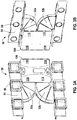
- FIGS 3A and 3B are front and rear perspective illustrations of the air chiller system 30 separated from the cart compartment 11.
- the air chiller unit 100 that provides the chilled air can be seen connected to the upper and lower ducts 52a, 52b, that feed respective cart compartment vent assemblies with cart compartment vent boots/vents 56.
- a chilled supply air vent 110 is connected to the upper duct 52a, and a return air vent 112 is connected to the lower duct.
- Figures 4A-4D illustrate the air chiller unit 100 in a number of views without any of the ductwork.
- the unit 100 is enclosed with a suitable case 102.
- Figure 4A shows the chilled supply air vents 110 and the return air vent 112, covered with a filter 111.
- the filters may be provided to ensure that contaminants do not enter the chiller unit 100.
- Figure 4B is a side view showing both the supply air 110 and return air 112 vents. It also shows the condenser supply 114 and condenser exhaust 116.
- Figures 4C and 4D are perspective views of the air chiller unit 100.
- FIG. 5 is a basic block diagram of the air chiller unit 100.
- the refrigerant is compressed and sent out of the compressor as a high temperature, high pressure, and superheated vapor.
- the refrigerant travels from Line 134 to an air-cooled condenser 130 where heat is rejected to a secondary air circuit by a condenser fan.
- the condenser changes the refrigerant from a high temperature and high pressure vapor to a high pressure sub cooled liquid.
- the refrigerant then travels from Line 136 into refrigerant liquid sight glass 170 and filter-drier 172 where the flow of liquid refrigerant can be monitored and the moisture and solid contaminants and debris are strained out of the refrigerant. It then moves through a vapor to liquid heat exchanger 160, from inlet 164 to outlet 166 where the liquid refrigerant is further sub-cooled by a vapor refrigerant from evaporator.
- the refrigerant continues to the Thermal Expansion Valve or TXV 176.
- the TXV 176 controls the quantity of liquid refrigerant being fed into the evaporator 150.
- the TXV 176 causes the pressure of liquid refrigerant to be reduced.
- the TXV 176 regulates the quantity of refrigerant through the evaporator to maintain a preset temperature difference or superheat between the evaporating refrigerant and the vapor leaving the evaporator 150.
- the expansion valve temperature sensing bulb 176a which is clamped to the outlet tube of evaporator, senses this temperature, and acts to modulate the feed of refrigerant through the TXV 176.
- the low temperature and low pressure refrigerant enters the evaporator 150, heat flow from galley cooing equipment and/or avionics equipment through the walls of the evaporator into the refrigerant. The boiling process of refrigerant continues until the refrigerant is completely evaporated.
- the superheated refrigerant vapor leaving the evaporator 150 travels into the vapor to liquid heat exchanger 160 where the vapor refrigerant is superheated further by the liquid refrigerant. It continues to the compressor suction line 142.
- the compressor 140 takes this superheated low pressure vapor and compresses it.
- the refrigerating cycle is continuous as long as the compressor is operating.
- the hot gas by pass solenoid valve or defrost valve 174 is used to stabilize refrigeration system at compressor starting, and to control the cooling output of the refrigeration system by allowing hot gas to warm up the cool evaporator. This causes a reduction in to cooling efficiency and a stabilizing of the chilled air temperatures.
- the refrigeration cycle results in frost formation on the surface of the evaporator. This frost will eventually build up to the point where it will restrict the air flow causing a loss of refrigeration capacity. To prevent this, the defrost valve will be energized or opened to initiates a defrost cycle which melts the frost. Once all of the frost has melted and the moisture has drained away. The system will then resume back to the refrigeration cycle.
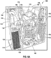
- FIGS 6A-6C show an exemplary placement of the chiller unit 100 components.
- the chiller unit 100 as a whole preferably has a flattened rectangular block shape in which all of the components are sized and mounted to fit within this bounded region enclosed by the case 102.
- the chiller unit 100 has a width of approximately 61 cms (24"), a height of approximately 50.8 cms (20"), and a depth of approximately 10.2cms (4").
- the chiller unit 100 has two main surfaces 103 each comprising a substantially greater area than the remaining four surfaces, where one of the greater area surfaces is designed to be adjacent to a back wall of the galley cart compartment.
- the layout of the components is in a generally flattened configuration such that a plane parallel to the main surfaces cuts through the condenser 130, the condenser fan 132, the compressor 140, the evaporator 150, and the evaporator fan 152.
- the condenser 130 is located in a lower bottom left corner (according to the Figure 6A view) of the chiller unit 100. Ambient air is pulled through the condenser 130 via a vacuum created by the condenser fan 132, located above the condenser 130 and connected adjacent to the condenser exhaust 116, which vents heated air into other parts of the aircraft outside of the galley cart compartment 11. This causes the heated pressurized refrigerant to condense into a liquid.
- the compressor 140 is located in a lower central region of the air chiller unit 100.
- the control circuitry, valves 174, 176, safety switches 178, and the like are located primarily above the compressor 140, which are situated in a compartment bounded by a first unsealed case partition 106 that permits heat created by the compressor 140 and associated components to be exhausted out of the condenser exhaust 116 via the condenser fan 132.
- the compressor 140 is also bounded by a generally second sealed case partition 108 that isolates the evaporator 150 and evaporator fans 152 to prevent heat generated within the unit 100 to not enter the galley cart compartment 11.
- the chiller unit 100 meets the following table of performance requirements: Table 1 POU Performance Requirements IP Unit SI Unit Air-Cooling Processes POU-A3 POU-A3 Ambient Temperature Air °F 85 °C 29.4 Chiller return air temperature Air °F 39.2 °C 4.0 Chiller supply air temperature Air °F 30 °C -1.1 Moisture content Air % 85 % 85.0 Evaporator air flow Air CFM 202 Liter/Sec 95.3 Evaporator fan pressure drop Air inH2O 1 mbar 2.5 Cooling capacity of chiller Air Btu/h 2150 w 629.7 Refrigeration System Evaporating pressure Refrigerant Psia 31.8 Bar 2.2 Evaporating temperature Refrigerant °F 18.1 °C -7.7 Cooling capacity Refrigerant Btu/h 2266 w 663.7 Condensing pressure Refrigerant Psia 185.9 Bar 12.8 Condensing temperature Refrig
- an air chiller system 30 that is a compact space and weight saving unit that is designed to maximize cooling capacity for up to, e.g., four trolley carts in an aircraft galley food service system 10. Due to its thin (shallow depth) design, it fits behind traditional galley cart ducting for a chilled galley compartment. Due to its close proximity to the galley carts, it eliminates the long chilled air supply ducts typically associated with remotely mounted air chiller units.
- the light-weight (approximately 9.1 kgs (20 lbs.)) compact design for this embodiment maximizes cooling capacity in a small space and represents a weight savings over traditional equivalently performing 40 lb. units. Additional weight savings for a typical installation of this unit is gained from the absence of long duct runs, long electrical cable runs, and heavy mounting structures normally associated with remote-mounted air chilling units.
- the unit is preferably designed to use less than 700 watts of power.
- air may be exhausted upward, or downward.
- the compact air chiller unit 100 is capable of a reverse mount, such that the supply air and the return air may be received/sent to the other side. This allows for flexible installations and galley ducting locations.
- the condenser air fan 132 may be mounted in a remote location, upstream in the exhaust duct to reduce, minimize, or eliminate condenser air noise. Baffling techniques may also be used to eliminate condenser air noise.
- the compact air chillers are designed for a chilled compartment galley wall mount, have flexible reversible mounting capabilities, provide for multiple cart cooling configurations (e.g., for one to four carts), and can have reversible fans for optimized cooling load balance.
- the present invention may be described in terms of functional block components and various processing steps. Such functional blocks may be realized by any number of components configured to perform the specified functions, within the limits of the attached claims. Furthermore, the present invention could employ any number of conventional techniques for electronics configuration, control and the like.
Landscapes
- Engineering & Computer Science (AREA)
- Chemical & Material Sciences (AREA)
- Combustion & Propulsion (AREA)
- Physics & Mathematics (AREA)
- Mechanical Engineering (AREA)
- Thermal Sciences (AREA)
- General Engineering & Computer Science (AREA)
- Devices That Are Associated With Refrigeration Equipment (AREA)
Description
- The invention relates to refrigeration equipment, and more specifically to equipment for providing and re-circulating chill air to an aircraft galley food service system, and for keeping the temperature of galley food and beverages at the required food storage temperature.
- Air chillers for aircraft galley food service systems are known. The existing air chillers designed for aircraft galley food service systems are installed in a remote location outside of the galley cart compartment because it has historically been difficult to locate air chillers close to galley. A further complicating factor is that galley designs are different for various aircraft configurations. Therefore, existing air chiller designs require refrigeration testing and balancing at the galley manufacturer and on first delivery for each new aircraft configuration.
- Normally, an air chiller needs to service more than one galley compartment. The chiller runs whenever a single compartment requires cooling, and therefore consumes more energy than is necessary in this situation, since it is also chilling other empty compartments. Large capacity chillers are typically equipped with a powerful evaporator fan to recirculate chill air to different galley compartments, and a large amount of electrical power is needed in order to overcome the pressure loss in the air ducting system.
- Known large capacity chillers produce significant air noise in chilled air outlets. The individual units are heavy, bulky, and not easy to handle. Given that there are many sizes of chillers available for different cooling requirements, airline customers typically must have many different chillers on hand in order to provide spare chillers when needed.
-
US2007/056305 discloses an air conditioner for installation at a window of a building in a wall which divides the outdoors and the indoors. The case for the air conditioner encloses conventional air conditioner components such as a compressor and heat exchangers. - According to the present invention there is provided an aircraft galley cart compartment as specified in attached claim 1. Various preferred features are set out in the attached sub-claims.
- The invention will be explained in more detail below with reference to various embodiments of the invention as illustrated in the drawings.
-
Figures 1A and 1B are front views of the chiller system installed within a galley cart compartment area; -
Figure 2 is a front view of the chiller system installed within the galley cart compartment area with the carts removed; -
Figures 3A and 3B are perspective front and perspective rear views of a mounted air chiller system; -
Figure 4A is a perspective view of the compact air chiller unit of the aircraft galley cart compartment according to an embodiment of the invention; -
Figure 4B is a side view of the compact air chiller unit; -
Figures 4C and 4D are perspective views of the chiller showing the air flow locations on the unit; -
Figure 5 is a block diagram illustrating the aircraft cooling system; -
Figure 6A is a perspective view of the chiller with cover removed showing the interior components; -
Figure 6B is a front view of the chiller with cover removed and showing the attached duct work; and -
Figure 6C is a front view of the interior components. -
Figures 1A and 1B illustrate an embodiment of an aircraft galleyfood services system 10 that uses a galley cart compartment 11 for holding one or moregalley food carts 20 in an enclosure area bounded by anouter case 12.Such food carts 20 are moved down the aisles of aircraft in order to serve meals and beverages. - In a typical configuration, such a galley compartment 11 is designed to hold a maximum of three
carts 20, but such a compartment could be designed to accommodate any number ofsuch carts 20.Figure 1A shows asingle cart 20 within the cart compartment 11, andFigure 1B shows the compartment 11 with twocarts 20. - An embodiment of the
air chiller system 30 can be seen mounted at the rear of the cart compartment 11. Thechiller system 30 comprises the following main components that are described in more detail below. Anair chiller unit 100 comprises the actual refrigeration components, and circulates chilled air via, e.g., anupper duct 52a (used, e.g., for a chilled air supply) and alower duct 52b (e.g., used for an air return). Each of theseducts 52a, b, are connected to a cartcompartment vent assembly 54 that each comprise a plurality ofcart compartment vents 56 that may comprise an interface boot. Eachcart 20 may have two corresponding vents (not shown) that interface with a corresponding pair ofcart compartment vents 56 on the cartcompartment vent assemblies 54 fed by therespective ducts 52a, b. In this way, eachcart 20 is connected with a chilled air supply and an air return. -
Figure 2 shows the positioning of theair chiller system 30 within the space of the galley cart compartment 11 in more detail. In this embodiment, thechiller system 30 is affixed to a rear and/or side wall of the cart compartment 11. The width of thechiller system 30 is such that the cart compartment can accommodate both thechiller system 30 along with anycarts 20 that are provided. Any know mechanisms may be used to mount thechiller system 30 within the cart compartment 11. As will be discussed in more detail below, the condenser supply 114 andcondenser exhaust 116 are interfaced with cutouts in a side wall of the cart compartment 11. -
Figures 3A and 3B are front and rear perspective illustrations of theair chiller system 30 separated from the cart compartment 11. In these views, theair chiller unit 100 that provides the chilled air can be seen connected to the upper andlower ducts vents 56. A chilledsupply air vent 110 is connected to theupper duct 52a, and areturn air vent 112 is connected to the lower duct. -
Figures 4A-4D illustrate theair chiller unit 100 in a number of views without any of the ductwork. Theunit 100 is enclosed with asuitable case 102.Figure 4A shows the chilledsupply air vents 110 and thereturn air vent 112, covered with afilter 111. The filters may be provided to ensure that contaminants do not enter thechiller unit 100.Figure 4B is a side view showing both thesupply air 110 and returnair 112 vents. It also shows thecondenser supply 114 andcondenser exhaust 116.Figures 4C and 4D are perspective views of theair chiller unit 100. -
Figure 5 is a basic block diagram of theair chiller unit 100. Starting at thecompressor 140, the refrigerant is compressed and sent out of the compressor as a high temperature, high pressure, and superheated vapor. - The refrigerant travels from
Line 134 to an air-cooledcondenser 130 where heat is rejected to a secondary air circuit by a condenser fan. The condenser changes the refrigerant from a high temperature and high pressure vapor to a high pressure sub cooled liquid. - The refrigerant then travels from Line 136 into refrigerant
liquid sight glass 170 and filter-drier 172 where the flow of liquid refrigerant can be monitored and the moisture and solid contaminants and debris are strained out of the refrigerant. It then moves through a vapor toliquid heat exchanger 160, frominlet 164 tooutlet 166 where the liquid refrigerant is further sub-cooled by a vapor refrigerant from evaporator. - The refrigerant continues to the Thermal Expansion Valve or
TXV 176. The TXV 176 controls the quantity of liquid refrigerant being fed into theevaporator 150. TheTXV 176 causes the pressure of liquid refrigerant to be reduced. TheTXV 176 regulates the quantity of refrigerant through the evaporator to maintain a preset temperature difference or superheat between the evaporating refrigerant and the vapor leaving theevaporator 150. As the temperature of the gas leaving the evaporator varies, the expansion valvetemperature sensing bulb 176a, which is clamped to the outlet tube of evaporator, senses this temperature, and acts to modulate the feed of refrigerant through theTXV 176. - The low temperature and low pressure refrigerant enters the
evaporator 150, heat flow from galley cooing equipment and/or avionics equipment through the walls of the evaporator into the refrigerant. The boiling process of refrigerant continues until the refrigerant is completely evaporated. - The superheated refrigerant vapor leaving the
evaporator 150 travels into the vapor toliquid heat exchanger 160 where the vapor refrigerant is superheated further by the liquid refrigerant. It continues to thecompressor suction line 142. Thecompressor 140 takes this superheated low pressure vapor and compresses it. The refrigerating cycle is continuous as long as the compressor is operating. - The hot gas by pass solenoid valve or defrost
valve 174 is used to stabilize refrigeration system at compressor starting, and to control the cooling output of the refrigeration system by allowing hot gas to warm up the cool evaporator. This causes a reduction in to cooling efficiency and a stabilizing of the chilled air temperatures. - The refrigeration cycle results in frost formation on the surface of the evaporator. This frost will eventually build up to the point where it will restrict the air flow causing a loss of refrigeration capacity. To prevent this, the defrost valve will be energized or opened to initiates a defrost cycle which melts the frost. Once all of the frost has melted and the moisture has drained away. The system will then resume back to the refrigeration cycle.
-
Figures 6A-6C show an exemplary placement of thechiller unit 100 components. Thechiller unit 100 as a whole preferably has a flattened rectangular block shape in which all of the components are sized and mounted to fit within this bounded region enclosed by thecase 102. In a preferred embodiment, thechiller unit 100 has a width of approximately 61 cms (24"), a height of approximately 50.8 cms (20"), and a depth of approximately 10.2cms (4"). - The
chiller unit 100 has twomain surfaces 103 each comprising a substantially greater area than the remaining four surfaces, where one of the greater area surfaces is designed to be adjacent to a back wall of the galley cart compartment. The layout of the components is in a generally flattened configuration such that a plane parallel to the main surfaces cuts through thecondenser 130, thecondenser fan 132, thecompressor 140, theevaporator 150, and theevaporator fan 152. - In this embodiment, the
condenser 130 is located in a lower bottom left corner (according to theFigure 6A view) of thechiller unit 100. Ambient air is pulled through thecondenser 130 via a vacuum created by thecondenser fan 132, located above thecondenser 130 and connected adjacent to thecondenser exhaust 116, which vents heated air into other parts of the aircraft outside of the galley cart compartment 11. This causes the heated pressurized refrigerant to condense into a liquid. - The
compressor 140 is located in a lower central region of theair chiller unit 100. The control circuitry,valves compressor 140, which are situated in a compartment bounded by a first unsealedcase partition 106 that permits heat created by thecompressor 140 and associated components to be exhausted out of thecondenser exhaust 116 via thecondenser fan 132. Thecompressor 140 is also bounded by a generally second sealedcase partition 108 that isolates theevaporator 150 andevaporator fans 152 to prevent heat generated within theunit 100 to not enter the galley cart compartment 11. - In a preferred embodiment, the
chiller unit 100 meets the following table of performance requirements:Table 1 POU Performance Requirements IP Unit SI Unit Air-Cooling Processes POU-A3 POU-A3 Ambient Temperature Air °F 85 °C 29.4 Chiller return air temperature Air °F 39.2 °C 4.0 Chiller supply air temperature Air ° F 30 °C -1.1 Moisture content Air % 85 % 85.0 Evaporator air flow Air CFM 202 Liter/Sec 95.3 Evaporator fan pressure drop Air inH2O 1 mbar 2.5 Cooling capacity of chiller Air Btu/h 2150 w 629.7 Refrigeration System Evaporating pressure Refrigerant Psia 31.8 Bar 2.2 Evaporating temperature Refrigerant °F 18.1 °C -7.7 Cooling capacity Refrigerant Btu/h 2266 w 663.7 Condensing pressure Refrigerant Psia 185.9 Bar 12.8 Condensing temperature Refrigerant °F 120 °C 48.9 Condenser air flow Air CFM 135 Liter/Sec 63.7 Condenser fan pressure drop Air inH2O 0.50 mbar 1.2 Condenser heat rejection Refrigerant Btu/h 3714 w 1087.7 Chiller discharge air temperature Air °F 120.6 °C 49.2 Power and COP Evaporator fan Air w 67.8 w 67.8 Condenser Fan Air w 22.7 w 22.7 Compressor Refrigerant w 593 w 593 Liquid pump PGW w w 0 Total Power Consumption w 683.5 w 683.5 COP 0.92 0.92 - Thus, what is provided is an
air chiller system 30 that is a compact space and weight saving unit that is designed to maximize cooling capacity for up to, e.g., four trolley carts in an aircraft galleyfood service system 10. Due to its thin (shallow depth) design, it fits behind traditional galley cart ducting for a chilled galley compartment. Due to its close proximity to the galley carts, it eliminates the long chilled air supply ducts typically associated with remotely mounted air chiller units. - The light-weight (approximately 9.1 kgs (20 lbs.)) compact design for this embodiment maximizes cooling capacity in a small space and represents a weight savings over traditional equivalently performing 40 lb. units. Additional weight savings for a typical installation of this unit is gained from the absence of long duct runs, long electrical cable runs, and heavy mounting structures normally associated with remote-mounted air chilling units. The unit is preferably designed to use less than 700 watts of power.
- In other embodiments of the compact
air chiller system 30, air may be exhausted upward, or downward. In further embodiments, the compactair chiller unit 100 is capable of a reverse mount, such that the supply air and the return air may be received/sent to the other side. This allows for flexible installations and galley ducting locations. In still another embodiment, thecondenser air fan 132 may be mounted in a remote location, upstream in the exhaust duct to reduce, minimize, or eliminate condenser air noise. Baffling techniques may also be used to eliminate condenser air noise. - In sum, the compact air chillers are designed for a chilled compartment galley wall mount, have flexible reversible mounting capabilities, provide for multiple cart cooling configurations (e.g., for one to four carts), and can have reversible fans for optimized cooling load balance.
- For the purposes of promoting an understanding of the principles of the invention, reference has been made to the preferred embodiments illustrated in the drawings, and specific language has been used to describe these embodiments. However, no limitation of the scope of the invention is intended by this specific language, and the invention should be construed to encompass all embodiments that would normally occur to one of ordinary skill in the art, within the scope of the attached claims.
- The present invention may be described in terms of functional block components and various processing steps. Such functional blocks may be realized by any number of components configured to perform the specified functions, within the limits of the attached claims. Furthermore, the present invention could employ any number of conventional techniques for electronics configuration, control and the like.
- The particular implementations shown and described herein are illustrative examples of the invention and are not intended to otherwise limit the scope of the invention in any way. For the sake of brevity, conventional aspects of the systems (and components of the individual operating components of the systems) may not be described in detail. Furthermore, the connecting lines, or connectors shown in the various figures presented are intended to represent exemplary functional relationships and/or physical or logical couplings between the various elements. It should be noted that many alternative or additional functional relationships, physical connections or logical connections may be present in a practical device. Moreover, no item or component is essential to the practice of the invention unless the element is specifically mentioned in the attached claim 1.
- The use of the terms "a" and "an" and "the" and similar referents in the context of describing the invention (especially in the context of the following claims) are to be construed to cover both the singular and the plural. Furthermore, recitation of ranges of values herein are merely intended to serve as a shorthand method of referring individually to each separate value falling within the range, unless otherwise indicated herein, and each separate value is incorporated into the specification as if it were individually recited herein. Finally, the steps of all methods described herein can be performed in any suitable order unless otherwise indicated herein or otherwise clearly contradicted by context.
- The words "mechanism" and "element" are intended to be used generally and are not limited solely to mechanical embodiments. Numerous modifications and adaptations will be readily apparent to those skilled in this art without departing from the scope of the present invention as set out in the attached claims.
-
- 10
- aircraft galley food services system
- 11
- galley cart compartment
- 12
- cart compartment outer case
- 20
- galley food cart
- 30
- air chiller system
- 50
- vent assembly
- 52a
- upper duct
- 52b
- lower duct
- 54
- cart compartment vent assembly
- 56
- cart compartment vent boots/cart compartment vents
- 100
- air chiller unit
- 102
- case
- 103
- case main surface
- 104
- power connection
- 106
- unsealed case partition
- 108
- sealed case partition
- 110
- chilled supply air vent
- 111
- filter
- 112
- return air vent
- 114
- condenser supply
- 116
- condenser exhaust
- 130
- condenser
- 132
- condenser fan
- 134
- condenser input line
- 136
- condenser output line
- 140
- compressor
- 142
- compressor input line
- 150
- evaporator
- 152
- evaporator fan
- 154
- evaporator input line
- 156
- evaporator output line
- 160
- heat exchanger
- 162
- compressor output
- 164
- condenser input
- 166
- evaporator output
- 168
- evaporator input
- 170
- sight glass
- 172
- filter/drier
- 174
- solenoid valve
- 176
- thermal expansion valve (TXV)
- 176a
- temperature sensing bulb
- 178
- pressure safety switch
Claims (11)
- An aircraft galley cart compartment (11) comprising:a cart compartment outer case (12) having a rear and side walls;a cart compartment vent assembly (54) comprising cart compartment vents (56);a point-of-use air chiller unit (100) mounted at the rear wall of the aircraft galley cart compartment (11), the air chiller unit (100) being enclosed with a case (102) which is a generally flattened rectangular case comprising two main surfaces (103) having a substantially larger surface area than four remaining surfaces of the case, the air chiller unit (100) further comprising:an air-cooled condenser (130);a compressor (140);an evaporator (150);an evaporator fan (152);a first unsealed wall partition (106) within the case that separates the condenser (130) from the compressor (140); anda second generally sealed wall partition (108) within the case that separates the evaporator from the compressor (140) and condenser (130);wherein the condenser, compressor, and evaporator are connected in a standard refrigeration manner; and wherein a plane parallel to the main surfaces passes through the condenser, the compressor, the evaporator, and the evaporator fan;the aircraft galley cart compartment further comprising upper and lower ducts (52a, 52b) that are respectively connected on one end to the chiller unit (100) for air supply and return air, and connected on an other end to the cart compartment vent assembly (54).
- The cart compartment (11) according to claim 1, wherein:the condenser is located in a lower portion of one side of the rectangular case;the evaporator is located in a lower portion of an opposite side of the rectangular case; andthe compressor is located in between the condenser and the evaporator.
- The cart compartment (11) according to any preceding claim, wherein the chiller unit (100) weighs approximately 9.1 kg (20 pounds) and is sized to fit within a food galley cart compartment (11).
- The cart compartment (11) according to any preceding claim, wherein the total power consumption is less than 700 watts.
- The cart compartment (11) according to any preceding claim, the chiller unit (100) further comprising a condenser fan (132) located within the case (102).
- The cart compartment (11) according to any preceding claim, further comprising a condenser air supply (114) and a condenser air exhaust (116) interfaced with cutouts in a side wall of the galley cart compartment (11).
- The cart compartment (11) according to any preceding claim, further comprising valves (174, 176) and safety switches (178) to control pressure in refrigeration lines (134, 136, 142, 154, 156).
- The cart compartment (11) according to any preceding claim, wherein one or more of the fans are reversible.
- The cart compartment (11) according to any preceding claim, further comprising a vapor to liquid heat exchanger (160) which exchanges heat between liquid refrigerant after exiting the condenser (130) and vapor refrigerant after exiting the evaporator (150) to sub-cool the liquid refrigerant and superheat the vapor refrigerant.
- The cart compartment (11) according to any preceding claim, further comprising a defrost valve (174) which initiates a defrost cycle to melt frost formed on a surface of the evaporator (150).
- The cart compartment (11) according to any preceding claim, wherein the generally flattened rectangular case (102) has a depth of approximately 10.2 cms (4 inches), a width of approximately 61 cm (24 inches), and a height of approximately 50.8 cms (20 inches).
Applications Claiming Priority (2)
| Application Number | Priority Date | Filing Date | Title |
|---|---|---|---|
| US15742709P | 2009-03-04 | 2009-03-04 | |
| PCT/US2010/025999 WO2010101972A1 (en) | 2009-03-04 | 2010-03-03 | Wall-mounted point-of-use air chiller for aircraft galley cart compartment |
Publications (3)
| Publication Number | Publication Date |
|---|---|
| EP2403728A1 EP2403728A1 (en) | 2012-01-11 |
| EP2403728A4 EP2403728A4 (en) | 2016-03-09 |
| EP2403728B1 true EP2403728B1 (en) | 2021-06-23 |
Family
ID=42677364
Family Applications (1)
| Application Number | Title | Priority Date | Filing Date |
|---|---|---|---|
| EP10749244.9A Active EP2403728B1 (en) | 2009-03-04 | 2010-03-03 | Aircraft galley cart compartment with point-of-use air chiller |
Country Status (6)
| Country | Link |
|---|---|
| US (1) | US9062909B2 (en) |
| EP (1) | EP2403728B1 (en) |
| JP (1) | JP5826034B2 (en) |
| AU (1) | AU2010221439B2 (en) |
| CA (1) | CA2753273C (en) |
| WO (1) | WO2010101972A1 (en) |
Families Citing this family (43)
| Publication number | Priority date | Publication date | Assignee | Title |
|---|---|---|---|---|
| EP2307827A1 (en) * | 2008-06-05 | 2011-04-13 | B/E Aerospace Inc. | Aircraft galley refrigeration system including a reduced weight and depth storage compartment cooling apparatus |
| WO2013033439A1 (en) | 2011-08-30 | 2013-03-07 | B/E Aerospace, Inc. | Reconfigurable chilled air outlet for an aircraft galley chiller |
| CN106949695A (en) * | 2012-03-22 | 2017-07-14 | B/E航空公司 | Vehicles refrigeration plant with steam circulation |
| US9359078B2 (en) * | 2012-03-28 | 2016-06-07 | B/E Aerospace, Inc. | Aircraft galley monument structure |
| US9862496B2 (en) | 2012-03-30 | 2018-01-09 | B/E Aerospace, Inc. | Aircraft galley chiller system |
| EP2650216B1 (en) * | 2012-04-13 | 2014-08-13 | Airbus Operations GmbH | Cooling arrangement |
| CN104640772A (en) * | 2012-07-20 | 2015-05-20 | 塞尔有限责任公司 | Cooling Concept Back Panel |
| US20140196486A1 (en) * | 2013-01-14 | 2014-07-17 | Hussmann Corporation | Refrigeration system with indoor condenser and remote fan |
| US9676483B2 (en) * | 2013-07-03 | 2017-06-13 | B/E Aerospace, Inc. | Aircraft galley air chiller system |
| US20150034290A1 (en) * | 2013-08-01 | 2015-02-05 | Carrier Corporation | Air handler with a leak free controls enclosure |
| US9840125B2 (en) * | 2013-08-30 | 2017-12-12 | B/E Aerospace, Inc. | Aircraft galley with air-through carts |
| US10239618B2 (en) | 2013-08-30 | 2019-03-26 | B/E Aerospace, Inc. | L shaped guide vanes for controlling and directing airflow in a galley chilled compartment |
| US9919575B2 (en) * | 2013-08-30 | 2018-03-20 | B/E Aerospace, Inc. | Device for reversing chiller airflow in an aircraft galley |
| US20150089968A1 (en) * | 2013-10-01 | 2015-04-02 | B/E Aerospace, Inc. | Aircraft air chiller with reduced profile |
| US10407173B2 (en) * | 2014-03-10 | 2019-09-10 | The Boeing Company | Dry ice draw through galley cooling |
| JP6419837B2 (en) * | 2014-03-24 | 2018-11-07 | ビーイー・エアロスペース・インコーポレーテッドB/E Aerospace, Inc. | Moving body cooling apparatus having liquid heat exhaust system |
| EP2933190B1 (en) * | 2014-04-14 | 2021-09-15 | Airbus Operations GmbH | Galley cooling system and method of operating a galley cooling system |
| EP2937284A1 (en) * | 2014-04-24 | 2015-10-28 | Airbus Operations GmbH | Galley cooling system and method of operating a galley cooling system |
| US9986822B2 (en) * | 2014-05-01 | 2018-06-05 | The Boeing Company | Method and apparatus for cooling an airline galley cart using a skin heat exchanger |
| US10016055B2 (en) | 2014-07-08 | 2018-07-10 | B/E Aerospace, Inc. | Compact liquid cooled, air through galley chiller |
| US9738389B2 (en) * | 2014-09-18 | 2017-08-22 | The Boeing Company | Systems and methods for cooling using galley monuments |
| CN104456999B (en) * | 2014-09-26 | 2016-10-05 | 西京学院 | A kind of airborne evaporation circulating system of plug-in monoblock type |
| US9802703B2 (en) * | 2014-10-28 | 2017-10-31 | The Boeing Company | Galley compartment for a galley system of an aircraft |
| CN105987553A (en) | 2015-02-03 | 2016-10-05 | 海信容声(广东)冰箱有限公司 | Ice storage device and refrigerator |
| DE102015102885A1 (en) * | 2015-02-27 | 2016-09-01 | Airbus Operations Gmbh | A system for producing a kitchen arrangement for a cabin of a vehicle with a main module and attachable thereto add-on modules, a kitchen arrangement and an aircraft with such a kitchen arrangement |
| US10492603B2 (en) | 2015-05-19 | 2019-12-03 | The Boeing Company | Systems and methods of cooling a galley of an aircraft |
| US9957050B2 (en) | 2015-05-19 | 2018-05-01 | The Boeing Company | Galley cart and galley system of an aircraft |
| KR20170087638A (en) * | 2016-01-21 | 2017-07-31 | 삼성전자주식회사 | Refrigerator and controlling method of the same |
| US10207807B2 (en) | 2016-04-13 | 2019-02-19 | The Boeing Company | Condensate removal system of an aircraft cooling system |
| US10472066B2 (en) | 2016-11-17 | 2019-11-12 | The Boeing Company | Chiller galley cart, galley, and method for cooling |
| US11136125B2 (en) * | 2017-03-29 | 2021-10-05 | Rockwell Collins, Inc. | Liquid chilled galley bar unit |
| DE102017126693A1 (en) * | 2017-11-14 | 2019-05-16 | Airbus Operations Gmbh | Cooling arrangement for a galley and galley |
| US10618660B2 (en) * | 2017-11-20 | 2020-04-14 | The Boeing Company | Systems and methods providing airflow to a flight deck |
| DE102017130722A1 (en) * | 2017-12-20 | 2019-06-27 | Airbus Operations Gmbh | Aircraft galley |
| EP4034462A1 (en) * | 2019-09-23 | 2022-08-03 | Safran Cabin Germany GmbH | Galley module for an aircraft and method for the open-loop and/or closed-loop control of the temperature in a food and/or drinks compartment of a galley module |
| US11286049B2 (en) * | 2019-11-12 | 2022-03-29 | B/E Aerospace, Inc. | Standard unit meal box compartment including air chiller |
| US11958615B2 (en) | 2020-03-27 | 2024-04-16 | B/E Aerospace, Inc. | Thermostatically controlled galley air extraction |
| EP3998211B1 (en) * | 2021-02-19 | 2023-04-05 | Lilium eAircraft GmbH | Self-supporting vapor cycle refrigeration system for an aircraft |
| US12150601B2 (en) * | 2021-06-18 | 2024-11-26 | B/E Aerospace, Inc. | Lavatory hand dryer |
| JP7811452B2 (en) * | 2021-09-30 | 2026-02-05 | 株式会社小松製作所 | Work machine and work machine control method |
| CN218069971U (en) * | 2022-06-30 | 2022-12-16 | 深圳市英维克科技股份有限公司 | Refrigerating device |
| US12130069B2 (en) | 2022-08-23 | 2024-10-29 | Peter Berkeley | Vehicle refrigeration system for food carts |
| EP4415197A1 (en) * | 2023-02-09 | 2024-08-14 | B/E Aerospace, Inc. | High voltage direct current powered aircraft appliances |
Citations (1)
| Publication number | Priority date | Publication date | Assignee | Title |
|---|---|---|---|---|
| US20070056305A1 (en) * | 2003-10-23 | 2007-03-15 | Yoon-Seob Eom | Window type air conditioner |
Family Cites Families (20)
| Publication number | Priority date | Publication date | Assignee | Title |
|---|---|---|---|---|
| US3277956A (en) * | 1961-10-26 | 1966-10-11 | Carrier Corp | Air heating and cooling apparatus |
| AU501924B2 (en) * | 1976-04-30 | 1979-07-05 | Tokyo Shibaura Electric Company Ltd. | Airconditioning apparatus |
| US4075867A (en) | 1976-12-30 | 1978-02-28 | Thermo King Corporation | Compact refrigeration unit |
| US4361014A (en) * | 1981-03-19 | 1982-11-30 | Sundstrand Corporation | Panel air chiller |
| US4437320A (en) * | 1982-05-11 | 1984-03-20 | Eklund Claes E | Transporter air chiller |
| JPS61231374A (en) * | 1985-04-03 | 1986-10-15 | 株式会社デンソー | Refrigeration installation for car |
| JPH0527852Y2 (en) * | 1987-11-07 | 1993-07-16 | ||
| JPH0259040U (en) * | 1988-10-25 | 1990-04-27 | ||
| JPH05332573A (en) * | 1992-06-01 | 1993-12-14 | Hitachi Ltd | Integral type air conditioner |
| JPH09229408A (en) * | 1996-02-21 | 1997-09-05 | Shimizu Corp | Air purifier |
| DE10316045B4 (en) | 2003-04-07 | 2008-11-27 | Rittal Gmbh & Co. Kg | Cooling system |
| JP2005134001A (en) * | 2003-10-29 | 2005-05-26 | Jamco Corp | Air chiller device |
| US7231778B2 (en) | 2004-03-29 | 2007-06-19 | Be Intellectual Property, Inc. | Cooling system for a commercial aircraft galley |
| JP4291730B2 (en) | 2004-04-26 | 2009-07-08 | 株式会社ジャムコ | Air chiller device |
| RU2007138610A (en) * | 2005-03-18 | 2009-04-27 | Кэрриэ Копэрейшн (US) | RACK FOR MOUNTING THE EVAPORATOR ASSEMBLY AND THE EVAPORATOR ASSEMBLY (OPTIONS) |
| JP4573734B2 (en) * | 2005-08-31 | 2010-11-04 | 進 久志 | Thermal insulation transport container and thermal insulation transport method |
| US7721564B2 (en) * | 2006-11-21 | 2010-05-25 | B/E Aerospace, Inc. | Wild frequency avionic refrigeration system and controller therefor |
| US8141377B2 (en) * | 2007-02-21 | 2012-03-27 | Bergstrom, Inc. | Truck electrified engine-off air conditioning system |
| US8056349B2 (en) * | 2007-08-13 | 2011-11-15 | B/E Aerospace, Inc. | Method and apparatus for maintaining a uniform temperature in a refrigeration system |
| US8171749B2 (en) | 2007-10-31 | 2012-05-08 | B/E Aerospace, Inc. | Ultra small air chiller for aircraft galley |
-
2010
- 2010-03-03 EP EP10749244.9A patent/EP2403728B1/en active Active
- 2010-03-03 WO PCT/US2010/025999 patent/WO2010101972A1/en not_active Ceased
- 2010-03-03 AU AU2010221439A patent/AU2010221439B2/en active Active
- 2010-03-03 JP JP2011553062A patent/JP5826034B2/en active Active
- 2010-03-03 CA CA2753273A patent/CA2753273C/en not_active Expired - Fee Related
- 2010-03-03 US US12/716,397 patent/US9062909B2/en active Active
Patent Citations (1)
| Publication number | Priority date | Publication date | Assignee | Title |
|---|---|---|---|---|
| US20070056305A1 (en) * | 2003-10-23 | 2007-03-15 | Yoon-Seob Eom | Window type air conditioner |
Also Published As
| Publication number | Publication date |
|---|---|
| CA2753273A1 (en) | 2010-09-10 |
| US9062909B2 (en) | 2015-06-23 |
| JP5826034B2 (en) | 2015-12-02 |
| US20100224726A1 (en) | 2010-09-09 |
| CA2753273C (en) | 2014-05-20 |
| AU2010221439A1 (en) | 2011-09-01 |
| EP2403728A1 (en) | 2012-01-11 |
| JP2012519624A (en) | 2012-08-30 |
| AU2010221439B2 (en) | 2014-02-20 |
| EP2403728A4 (en) | 2016-03-09 |
| WO2010101972A1 (en) | 2010-09-10 |
Similar Documents
| Publication | Publication Date | Title |
|---|---|---|
| US9062909B2 (en) | Wall-mounted point-of-use air chiller for aircraft galley cart compartment | |
| EP2750971B1 (en) | Reconfigurable chilled air outlet for an aircraft galley chiller | |
| US10488084B2 (en) | Vehicle refrigeration equipment having a vapor cycle system | |
| EP3123085B1 (en) | Vehicle refrigeration equipment having a liquid heat rejection system | |
| US8171749B2 (en) | Ultra small air chiller for aircraft galley | |
| EP3017256B1 (en) | Aircraft galley air chiller system | |
| EP2830942B1 (en) | Aircraft galley chiller system | |
| EP3705402A1 (en) | Divided refrigeration system for aircraft galley cooling | |
| AU2018354028B2 (en) | Air handling system and method for forming an air handling unit | |
| HK1166291B (en) | Aircraft galley cart compartment with point-of-use air chiller | |
| US11686522B2 (en) | Chiller systems | |
| US20070089453A1 (en) | Refrigeration system with distributed compressors |
Legal Events
| Date | Code | Title | Description |
|---|---|---|---|
| PUAI | Public reference made under article 153(3) epc to a published international application that has entered the european phase |
Free format text: ORIGINAL CODE: 0009012 |
|
| 17P | Request for examination filed |
Effective date: 20110812 |
|
| AK | Designated contracting states |
Kind code of ref document: A1 Designated state(s): AT BE BG CH CY CZ DE DK EE ES FI FR GB GR HR HU IE IS IT LI LT LU LV MC MK MT NL NO PL PT RO SE SI SK SM TR |
|
| DAX | Request for extension of the european patent (deleted) | ||
| RIN1 | Information on inventor provided before grant (corrected) |
Inventor name: HA, THANG Inventor name: WHISLER, STEVEN Inventor name: OSWALD, IAN Inventor name: LU, QIAO Inventor name: BIRKMANN, TIMOTHY, ANDREW Inventor name: BATES, EDWARD, J. |
|
| REG | Reference to a national code |
Ref country code: HK Ref legal event code: DE Ref document number: 1166291 Country of ref document: HK |
|
| RA4 | Supplementary search report drawn up and despatched (corrected) |
Effective date: 20160209 |
|
| RIC1 | Information provided on ipc code assigned before grant |
Ipc: F25D 23/00 20060101ALI20160203BHEP Ipc: F25D 17/06 20060101ALI20160203BHEP Ipc: B60H 1/32 20060101AFI20160203BHEP |
|
| STAA | Information on the status of an ep patent application or granted ep patent |
Free format text: STATUS: EXAMINATION IS IN PROGRESS |
|
| 17Q | First examination report despatched |
Effective date: 20180830 |
|
| GRAP | Despatch of communication of intention to grant a patent |
Free format text: ORIGINAL CODE: EPIDOSNIGR1 |
|
| STAA | Information on the status of an ep patent application or granted ep patent |
Free format text: STATUS: GRANT OF PATENT IS INTENDED |
|
| INTG | Intention to grant announced |
Effective date: 20210113 |
|
| GRAS | Grant fee paid |
Free format text: ORIGINAL CODE: EPIDOSNIGR3 |
|
| GRAA | (expected) grant |
Free format text: ORIGINAL CODE: 0009210 |
|
| STAA | Information on the status of an ep patent application or granted ep patent |
Free format text: STATUS: THE PATENT HAS BEEN GRANTED |
|
| AK | Designated contracting states |
Kind code of ref document: B1 Designated state(s): AT BE BG CH CY CZ DE DK EE ES FI FR GB GR HR HU IE IS IT LI LT LU LV MC MK MT NL NO PL PT RO SE SI SK SM TR |
|
| REG | Reference to a national code |
Ref country code: GB Ref legal event code: FG4D |
|
| REG | Reference to a national code |
Ref country code: CH Ref legal event code: EP |
|
| REG | Reference to a national code |
Ref country code: DE Ref legal event code: R096 Ref document number: 602010067157 Country of ref document: DE Ref country code: AT Ref legal event code: REF Ref document number: 1404012 Country of ref document: AT Kind code of ref document: T Effective date: 20210715 |
|
| REG | Reference to a national code |
Ref country code: IE Ref legal event code: FG4D |
|
| REG | Reference to a national code |
Ref country code: LT Ref legal event code: MG9D |
|
| PG25 | Lapsed in a contracting state [announced via postgrant information from national office to epo] |
Ref country code: HR Free format text: LAPSE BECAUSE OF FAILURE TO SUBMIT A TRANSLATION OF THE DESCRIPTION OR TO PAY THE FEE WITHIN THE PRESCRIBED TIME-LIMIT Effective date: 20210623 Ref country code: BG Free format text: LAPSE BECAUSE OF FAILURE TO SUBMIT A TRANSLATION OF THE DESCRIPTION OR TO PAY THE FEE WITHIN THE PRESCRIBED TIME-LIMIT Effective date: 20210923 Ref country code: FI Free format text: LAPSE BECAUSE OF FAILURE TO SUBMIT A TRANSLATION OF THE DESCRIPTION OR TO PAY THE FEE WITHIN THE PRESCRIBED TIME-LIMIT Effective date: 20210623 Ref country code: LT Free format text: LAPSE BECAUSE OF FAILURE TO SUBMIT A TRANSLATION OF THE DESCRIPTION OR TO PAY THE FEE WITHIN THE PRESCRIBED TIME-LIMIT Effective date: 20210623 |
|
| REG | Reference to a national code |
Ref country code: AT Ref legal event code: MK05 Ref document number: 1404012 Country of ref document: AT Kind code of ref document: T Effective date: 20210623 |
|
| PG25 | Lapsed in a contracting state [announced via postgrant information from national office to epo] |
Ref country code: NO Free format text: LAPSE BECAUSE OF FAILURE TO SUBMIT A TRANSLATION OF THE DESCRIPTION OR TO PAY THE FEE WITHIN THE PRESCRIBED TIME-LIMIT Effective date: 20210923 Ref country code: LV Free format text: LAPSE BECAUSE OF FAILURE TO SUBMIT A TRANSLATION OF THE DESCRIPTION OR TO PAY THE FEE WITHIN THE PRESCRIBED TIME-LIMIT Effective date: 20210623 Ref country code: GR Free format text: LAPSE BECAUSE OF FAILURE TO SUBMIT A TRANSLATION OF THE DESCRIPTION OR TO PAY THE FEE WITHIN THE PRESCRIBED TIME-LIMIT Effective date: 20210924 Ref country code: SE Free format text: LAPSE BECAUSE OF FAILURE TO SUBMIT A TRANSLATION OF THE DESCRIPTION OR TO PAY THE FEE WITHIN THE PRESCRIBED TIME-LIMIT Effective date: 20210623 |
|
| REG | Reference to a national code |
Ref country code: NL Ref legal event code: MP Effective date: 20210623 |
|
| PG25 | Lapsed in a contracting state [announced via postgrant information from national office to epo] |
Ref country code: AT Free format text: LAPSE BECAUSE OF FAILURE TO SUBMIT A TRANSLATION OF THE DESCRIPTION OR TO PAY THE FEE WITHIN THE PRESCRIBED TIME-LIMIT Effective date: 20210623 Ref country code: ES Free format text: LAPSE BECAUSE OF FAILURE TO SUBMIT A TRANSLATION OF THE DESCRIPTION OR TO PAY THE FEE WITHIN THE PRESCRIBED TIME-LIMIT Effective date: 20210623 Ref country code: PT Free format text: LAPSE BECAUSE OF FAILURE TO SUBMIT A TRANSLATION OF THE DESCRIPTION OR TO PAY THE FEE WITHIN THE PRESCRIBED TIME-LIMIT Effective date: 20211025 Ref country code: NL Free format text: LAPSE BECAUSE OF FAILURE TO SUBMIT A TRANSLATION OF THE DESCRIPTION OR TO PAY THE FEE WITHIN THE PRESCRIBED TIME-LIMIT Effective date: 20210623 Ref country code: RO Free format text: LAPSE BECAUSE OF FAILURE TO SUBMIT A TRANSLATION OF THE DESCRIPTION OR TO PAY THE FEE WITHIN THE PRESCRIBED TIME-LIMIT Effective date: 20210623 Ref country code: SM Free format text: LAPSE BECAUSE OF FAILURE TO SUBMIT A TRANSLATION OF THE DESCRIPTION OR TO PAY THE FEE WITHIN THE PRESCRIBED TIME-LIMIT Effective date: 20210623 Ref country code: SK Free format text: LAPSE BECAUSE OF FAILURE TO SUBMIT A TRANSLATION OF THE DESCRIPTION OR TO PAY THE FEE WITHIN THE PRESCRIBED TIME-LIMIT Effective date: 20210623 Ref country code: EE Free format text: LAPSE BECAUSE OF FAILURE TO SUBMIT A TRANSLATION OF THE DESCRIPTION OR TO PAY THE FEE WITHIN THE PRESCRIBED TIME-LIMIT Effective date: 20210623 Ref country code: CZ Free format text: LAPSE BECAUSE OF FAILURE TO SUBMIT A TRANSLATION OF THE DESCRIPTION OR TO PAY THE FEE WITHIN THE PRESCRIBED TIME-LIMIT Effective date: 20210623 |
|
| PG25 | Lapsed in a contracting state [announced via postgrant information from national office to epo] |
Ref country code: PL Free format text: LAPSE BECAUSE OF FAILURE TO SUBMIT A TRANSLATION OF THE DESCRIPTION OR TO PAY THE FEE WITHIN THE PRESCRIBED TIME-LIMIT Effective date: 20210623 |
|
| REG | Reference to a national code |
Ref country code: DE Ref legal event code: R097 Ref document number: 602010067157 Country of ref document: DE |
|
| PG25 | Lapsed in a contracting state [announced via postgrant information from national office to epo] |
Ref country code: DK Free format text: LAPSE BECAUSE OF FAILURE TO SUBMIT A TRANSLATION OF THE DESCRIPTION OR TO PAY THE FEE WITHIN THE PRESCRIBED TIME-LIMIT Effective date: 20210623 |
|
| PLBE | No opposition filed within time limit |
Free format text: ORIGINAL CODE: 0009261 |
|
| STAA | Information on the status of an ep patent application or granted ep patent |
Free format text: STATUS: NO OPPOSITION FILED WITHIN TIME LIMIT |
|
| 26N | No opposition filed |
Effective date: 20220324 |
|
| PG25 | Lapsed in a contracting state [announced via postgrant information from national office to epo] |
Ref country code: IT Free format text: LAPSE BECAUSE OF FAILURE TO SUBMIT A TRANSLATION OF THE DESCRIPTION OR TO PAY THE FEE WITHIN THE PRESCRIBED TIME-LIMIT Effective date: 20210623 |
|
| PG25 | Lapsed in a contracting state [announced via postgrant information from national office to epo] |
Ref country code: MC Free format text: LAPSE BECAUSE OF FAILURE TO SUBMIT A TRANSLATION OF THE DESCRIPTION OR TO PAY THE FEE WITHIN THE PRESCRIBED TIME-LIMIT Effective date: 20210623 |
|
| REG | Reference to a national code |
Ref country code: CH Ref legal event code: PL |
|
| REG | Reference to a national code |
Ref country code: BE Ref legal event code: MM Effective date: 20220331 |
|
| PG25 | Lapsed in a contracting state [announced via postgrant information from national office to epo] |
Ref country code: LU Free format text: LAPSE BECAUSE OF NON-PAYMENT OF DUE FEES Effective date: 20220303 Ref country code: LI Free format text: LAPSE BECAUSE OF NON-PAYMENT OF DUE FEES Effective date: 20220331 Ref country code: IE Free format text: LAPSE BECAUSE OF NON-PAYMENT OF DUE FEES Effective date: 20220303 Ref country code: CH Free format text: LAPSE BECAUSE OF NON-PAYMENT OF DUE FEES Effective date: 20220331 |
|
| PG25 | Lapsed in a contracting state [announced via postgrant information from national office to epo] |
Ref country code: BE Free format text: LAPSE BECAUSE OF NON-PAYMENT OF DUE FEES Effective date: 20220331 |
|
| REG | Reference to a national code |
Ref country code: DE Ref legal event code: R082 Ref document number: 602010067157 Country of ref document: DE Representative=s name: KRAUS & LEDERER PARTGMBB, DE |
|
| PG25 | Lapsed in a contracting state [announced via postgrant information from national office to epo] |
Ref country code: HU Free format text: LAPSE BECAUSE OF FAILURE TO SUBMIT A TRANSLATION OF THE DESCRIPTION OR TO PAY THE FEE WITHIN THE PRESCRIBED TIME-LIMIT; INVALID AB INITIO Effective date: 20100303 |
|
| PG25 | Lapsed in a contracting state [announced via postgrant information from national office to epo] |
Ref country code: MK Free format text: LAPSE BECAUSE OF FAILURE TO SUBMIT A TRANSLATION OF THE DESCRIPTION OR TO PAY THE FEE WITHIN THE PRESCRIBED TIME-LIMIT Effective date: 20210623 Ref country code: CY Free format text: LAPSE BECAUSE OF FAILURE TO SUBMIT A TRANSLATION OF THE DESCRIPTION OR TO PAY THE FEE WITHIN THE PRESCRIBED TIME-LIMIT Effective date: 20210623 |
|
| PG25 | Lapsed in a contracting state [announced via postgrant information from national office to epo] |
Ref country code: MT Free format text: LAPSE BECAUSE OF FAILURE TO SUBMIT A TRANSLATION OF THE DESCRIPTION OR TO PAY THE FEE WITHIN THE PRESCRIBED TIME-LIMIT Effective date: 20210623 |
|
| PGFP | Annual fee paid to national office [announced via postgrant information from national office to epo] |
Ref country code: DE Payment date: 20250218 Year of fee payment: 16 |
|
| PGFP | Annual fee paid to national office [announced via postgrant information from national office to epo] |
Ref country code: FR Payment date: 20250218 Year of fee payment: 16 |
|
| PGFP | Annual fee paid to national office [announced via postgrant information from national office to epo] |
Ref country code: GB Payment date: 20250221 Year of fee payment: 16 |
|
| PG25 | Lapsed in a contracting state [announced via postgrant information from national office to epo] |
Ref country code: TR Free format text: LAPSE BECAUSE OF FAILURE TO SUBMIT A TRANSLATION OF THE DESCRIPTION OR TO PAY THE FEE WITHIN THE PRESCRIBED TIME-LIMIT Effective date: 20210623 |