EP2403293B1 - Verfahren und vorrichtung zur benutzerübergabe an einen heimatknoten - Google Patents
Verfahren und vorrichtung zur benutzerübergabe an einen heimatknoten Download PDFInfo
- Publication number
- EP2403293B1 EP2403293B1 EP09840645.7A EP09840645A EP2403293B1 EP 2403293 B1 EP2403293 B1 EP 2403293B1 EP 09840645 A EP09840645 A EP 09840645A EP 2403293 B1 EP2403293 B1 EP 2403293B1
- Authority
- EP
- European Patent Office
- Prior art keywords
- user
- relocation request
- home nodeb
- request message
- message
- Prior art date
- Legal status (The legal status is an assumption and is not a legal conclusion. Google has not performed a legal analysis and makes no representation as to the accuracy of the status listed.)
- Active
Links
Images




Classifications
-
- H—ELECTRICITY
- H04—ELECTRIC COMMUNICATION TECHNIQUE
- H04W—WIRELESS COMMUNICATION NETWORKS
- H04W36/00—Hand-off or reselection arrangements
- H04W36/0005—Control or signalling for completing the hand-off
- H04W36/0011—Control or signalling for completing the hand-off for data sessions of end-to-end connection
- H04W36/0033—Control or signalling for completing the hand-off for data sessions of end-to-end connection with transfer of context information
-
- H—ELECTRICITY
- H04—ELECTRIC COMMUNICATION TECHNIQUE
- H04W—WIRELESS COMMUNICATION NETWORKS
- H04W36/00—Hand-off or reselection arrangements
- H04W36/24—Reselection being triggered by specific parameters
- H04W36/30—Reselection being triggered by specific parameters by measured or perceived connection quality data
- H04W36/302—Reselection being triggered by specific parameters by measured or perceived connection quality data due to low signal strength
Definitions
- the present invention relates to the communication field, and specifically, to a method and an apparatus for a user handing over to a home NodeB.
- a home NodeB is a small and low-power base station and deployed at indoor places such as homes and offices, and mainly aims at providing a higher service rate and lower fees required by high rate services for the users, and also makes up for the shortcomings in coverage of existing distributed cellular wireless communication systems.
- the home NodeB has advantages of benefits, convenience, low power output, plug and play, and etc.
- the home NodeB accesses a core network via a logical network element, i.e. a home NodeB gateway, and as shown in Figure 1 , the home NodeB gateway mainly executes the following functions: verifying the security of the home NodeB, processing the registration of the home NodeB, performing working maintenance and management on the home NodeB, configuring and controlling the home NodeB according to the requirements of operators, and being in charge of exchanging data between the core network and the home NodeB.
- a user of the home NodeB needs to conduct relevant registration at the home NodeB gateway before using the home NodeB, and makes the gateway store context information of the user through a user registration flow, so that the home NodeB gateway performs management operations on the signaling message of the user.
- the registration process of a user of the home NodeB is shown in Figure 2 , specifically comprising the steps as follows.
- a user needs to establish an RRC (Radio Resource Control) connection as a bearer of the signaling message or service data before conducting communication.
- RRC Radio Resource Control
- the user triggers the registration process through initializing an NAS (Non Access Stratum) message
- the message type can be an attachment message, a location/Routing area update message, a service request message and etc.
- the home NodeB does not find any context identifier information of the user and then sends a registration request message to the home NodeB gateway to register user information at the home NodeB gateway, and the contents of the message comprise information such as the type of the registration, the IMSI (International Mobile Subscriber Identify) identifier of the user, a home NodeB identifier, and etc.
- IMSI International Mobile Subscriber Identify
- the home NodeB gateway verifies the ability of the user which accesses the home NodeB, if it allows the user to use resources provided by the home NodeB, accepts the registration, establishes a user context, and carries user context identifier information in a registration response message replied to the home NodeB.
- the home NodeB gateway transparently forwards an NAS message sent from the user to the core network without performing any processing on the message.
- the core network performs starting authentication and a security flow to verify the user according to the received NAS message.
- the prior art must perform user registration process to make the home NodeB and the home NodeB gateway obtain a user context identifier, and the home NodeB and the home NodeB gateway use this identifier to distinguish that a signaling transmitted at an RUA (RANAP User Adaptation) protocol layer belongs to RANAP (Radio Access Network Application Part) message of which user, and provide adaptation between an RANAP and an SCTP (Stream Control Transmission Protocol).
- RUA RANAP User Adaptation
- SCTP Stream Control Transmission Protocol
- the present invention provides method and apparatus for a user handing over to a home NodeB, to solve the problem in the prior art that the handover procedure cannot be completed normally if a target cell is a home NodeB when a user performs cell handover.
- a method for a user handing over to a home NodeB is provided.
- the method for a user handing over to a home NodeB comprises:
- Step A comprises:
- Step A also comprises:
- step B the step of generating a user context for the user according to the relocation request message and allocating a user context identifier for the user context comprises:
- step A also comprises:
- step B the step of generating a user context for the user according to the relocation request message and allocating a user context identifier for the user context comprises:
- step B the step of sending the user context identifier and the relocation request message to the target home NodeB comprises:
- step C the method of the present invention further comprises the following step:
- an apparatus for a user handing over to a home NodeB is provided.
- the apparatus for a user handing over to a home NodeB comprises: a relocation request message receiving unit, configured to receive, when a user initiates a handover procedure from a source NodeB to a target home NodeB, a relocation request message sent from a mobility management unit of a core network to which the source NodeB belongs; a context identifier allocating unit, configured to generate a user context for the user according to the relocation request message received by the relocation reuqest message receiving unit, allocate a user context identifier for the user context, and send the user context identifier and the relocation request message to the target home NodeB for processing; and a request acknowledgement message sending unit, configured to send a relocation request acknowledgement message to the mobility management unit of the core network when the relocation request acknowledgement message replied by the target home NodeB is received.
- the context identifier allocating unit further comprises: an identifier information judging subunit, the first context identifier allocating subunit, the second context identifier allocating subunit and a message sending subunit, wherein, the identifier information judging subunit is configured to perform judgment according to the relocation request message sent from the relocation request message sending unit, trigger the first context identifier allocating subunit when the relocation request message carries a user permanent identifier, and trigger the second context identifier allocating subunit when the relocation request message does not carry a user permanent identifier; the first context identifier allocating subunit is configured to perform search according to the user permanent identifier in the relocation request message, and generate the user context for the user if the user has not performed registration and allocate the user context identifier for the user context; the second context identifier allocating subunit is configured to generate the user context for the user by using an Iu connection identifier in the relocation request message as a temporary user identifier and allocate the user context identifier for the user context; and the identifier
- the apparatus provided by the present invention further comprises: a synchronization process establishing unit, configured to send a relocation command via the mobility management unit of the core network to trigger the source NodeB to initiate a synchronization process from the user to the target home NodeB.
- a synchronization process establishing unit configured to send a relocation command via the mobility management unit of the core network to trigger the source NodeB to initiate a synchronization process from the user to the target home NodeB.
- the method provided by the present invention successfully solves the following problem: when a user performs cell handover, if a target NodeB of the handover procedure is a home NodeB, signaling messages between the home NodeB and the home NodeB gateway cannot be corresponded as the home NodeB gateway lacks a user context identifier, and thus the handover procedure cannot be successfully performed, and the present invention ensures the handover procedure of a user between cells more fluent.
- the present invention provide a method and an apparatus for a user handing over to a home NodeB, to solve the problem in the prior art that the handover procedure cannot be completed normally if a target cell is a home NodeB when a user performs cell handover.
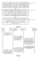
- Figure 3 is a flow chart of a method for a user handing over to a home NodeB provided by an embodiment of the present invention, and as shown in Figure 3 , the flow chart comprises the steps S301 to S303 as follows.
- Step S301 when a user initiates a handover procedure from a source NodeB to a target home NodeB, a target home NodeB gateway receives a relocation request message from a mobility management unit of a core network.
- the step specifically comprises:
- Step S302 the target home NodeB gateway generates a user context for the user according to the relocation request message, allocates a user context identifier for the user context, and sends the user context identifier and the relocation request message to the target home NodeB.
- step S301 uses the above implementation manners (1) and (2), in this step, the process of generating a user context for the user according to the relocation request message and allocating a user context identifier for the user context specifically comprise:
- step S301 uses the above implementation manner (3), in this step, the process of generating a user context for the user according to the relocation request message and allocating a user context identifier for the user context specifically comprise:
- the process of sending the user context identifier and the relocation request message to the target home NodeB specifically comprises:
- Step S303 when receiving a relocation request acknowledgement message replied by the target home NodeB, the target home NodeB gateway sends the relocation request acknowledgement message to the mobility management unit of the core network.
- the method further comprises the following step:
- the method provided by the present invention solves the following problem: when a user performs cell handover, if a target NodeB to be handed over to is a home NodeB, signaling messages between the home NodeB and the home NodeB gateway cannot be corresponded as the home NodeB gateway lacks a user context identifier, and thus the handover procedure cannot be successfully performed.
- Embodiments 1-6 are embodiments showing the implementing manners of a user handing over from a macro base station to a target home NodeB.
- Figure 4 is a flow chart of a method for a user handing over to a home NodeB provided by embodiment 1 of the present invention, and as shown in Figure 4 , the flow chart comprises the steps S401 to S406 as follows.
- Step S401 the macro base station judges to initiate a handover flow according to a measurement report reported by the user and sends the relocation request message to the mobility management unit of the core network, wherein the relocation request message carries information such as a target NodeB identifier.
- Step S402 after receiving the relocation request message, the mobility management unit of the core network makes judgment according to the target NodeB identifier information carried in the relocation request message, and if it finds that the target NodeB to be handed over to is a home NodeB, it carries the permanent identifier IMSI of the user in the relocation request message sent to the target home NodeB gateway.
- the macro base station (or source home NodeB) and the target home NodeB in this embodiment and the following embodiments are managed by the same mobility management unit of the core network.
- a source mobility management unit of the core network sends information, such as a user mobility management context, a bearer context and a target NodeB identifier, which is desired for completing the handover procedure, to a target mobility management unit of the core network by forwarding the relocation request message, and the target mobility management unit of the core network sends the relocation request message to the target home NodeB gateway according to the method in this step.
- Step S403 the target home NodeB gateway performs search according to the user permanent identifier IMSI in the relocation request message, if it finds that the user has not performed registration, it generates a user context for the user and allocates a user context identifier for the user context, and encapsulates the user context identifier in an RUA connection message together with the relocation request message and sends the RUA connection message to the target home NodeB.
- Step S404 the target home NodeB receives the RUA connection message and makes judgment according to the message, and when the target home NodeB does not have the context identifier of the user, it stores the user context identifier as received and replies a relocation request acknowledgement message.
- the relocation request acknowledgement message as replied is encapsulated in an RUA direct transfer message which also carries the user context identifier to distinguish the corresponding relationship between the message and the user.
- Step S405 the target home NodeB gateway receives the RUA direct transfer message and sends the relocation request acknowledgement message to the mobility management unit of the core network to notify that handover preparation at the target side has been completed.
- Step S406 the mobility management unit of the core network triggers the macro base station via a relocation command to initiate a synchronization process from the user to the target home NodeB.
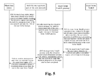
- Figure 5 is a flow chart of a method for a user handing over to a home NodeB provided by embodiment 2 of the present invention, and as shown in Figure 5 , the flow chart comprises the steps S501 to S506 as follows.
- Step S501 the macro base station judges to initiate a handover flow according to a measurement report reported by the user, and when the macro base station is able to judge that a target NodeB to be handed over to is a home NodeB according to the configuration information of the target NodeB to be handed over to, it adds the permanent identifier IMSI of the user in the relocation request message sent to the mobility management unit of the core network.
- the relocation request message also carries information such as a target NodeB identifier.
- Step S502 after receiving the relocation request message, the mobility management unit of the core network sends the relocation request message to the target home NodeB gateway.
- Step S503 the target home NodeB gateway performs search according to the user permanent identifier IMSI in the relocation request message, if it finds that the user has not performed registration, it generates a user context for the user and allocates a user context identifier, and encapsulates the user context identifier in an RUA connection message together with the relocation request message and sends the RUA connection message to the target home NodeB.
- Step S504 the target home NodeB receives the RUA connection message and makes judgment according to the message, and when the target home NodeB does not have the context identifier of the user, it stores the user context identifier as received and replies a relocation request acknowledgement message.
- the relocation request acknowledgement message as replied is encapsulated in an RUA direct transfer message which also carries the user context identifier to distinguish the corresponding relationship between the message and the user.
- Step S505 the target home NodeB gateway receives the RUA direct transfer message and sends the relocation request acknowledgement message to the mobility management unit of the core network to notify that handover preparation at the target side has been completed.
- Step S506 the mobility management unit of the core network triggers the macro base station via a relocation command to initiate a synchronization process from the user to the target home NodeB.
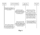
- Figure 6 is a flow chart of a method for a user handing over to a home NodeB provided by embodiment 3 of the present invention, and as shown in Figure 6 , the flow chart comprises the steps S601 to S606 as follows.
- Step S601 the macro base station judges to initiate a handover flow according to a measurement report reported by the user and sends a relocation request message to the mobility management unit of the core network, wherein the relocation request message carries information such as a target NodeB identifier.
- Step S602 after receiving the relocation request message, the mobility management unit of the core network sends a relocation request message to the target home NodeB gateway according to target NodeB identifier information carried in the relocation request message.
- Step S603 by using an Iu connection identifier in the relocation request message as a temporary user identifier, the target home NodeB gateway generates a user context for the user and allocates a user context identifier, and encapsulates the user context identifier in an RUA connection message together with the relocation request message and sends the RUA connection message to the target home NodeB.
- Step S604 the target home NodeB receives the RUA connection message and makes judgment according to the message, and when the target home NodeB does not have the context identifier of the user, it stores the user context identifier as received and replies a relocation request acknowledgement message.
- the relocation request acknowledgement message as replied is encapsulated in an RUA direct transfer message which also carries the user context identifier to distinguish the corresponding relationship between the message and the user.
- Step S605 the target home NodeB gateway receives the RUA direct transfer message and sends the relocation request acknowledgement message to the mobility management unit of the core network to notify that handover preparation at the target side has been completed.
- Step S606 the mobility management unit of the core network triggers the macro base station via a relocation command to initiate a synchronization process from the user to the target home NodeB.
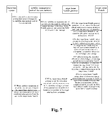
- Figure 7 is a flow chart of a method for a user handing over to a home NodeB provided by embodiment 4 of the present invention, and as shown in Figure 7 , the flow comprises the steps S701 to S708 as follows.
- Step S701 the macro base station judges to initiate a handover flow according to a measurement report reported by the user and sends a relocation request message to the mobility management unit of the core network, wherein the relocation request message carries information such as a target NodeB identifier.
- Step S702 after receiving the relocation request message, the mobility management unit of the core network makes judgment according to the target NodeB identifier information carried in the relocation request message, and if it finds that a target NodeB to be handed over to is a home NodeB, it carries the permanent identifier IMSI of the user in the relocation request message sent to the target home NodeB gateway.
- Step S703 the target home NodeB gateway performs search according to the user permanent identifier IMSI in the relocation request message, if it finds that the user has not performed registration, it generates a user context for the user and allocates a user context identifier, and sends the identifier to the target home NodeB via an identifier allocation message newly defined at an HNBAP (HNB Application Part).
- HNBAP HNB Application Part
- Step S704 the target home NodeB receives the HNBAP identifier allocation message and makes judgment according to the user context identifier in the message, and when the target home NodeB does not have the user context identifier, it stores the user context identifier as received and replies an identifier allocation acknowledgement message to the target home NodeB gateway.
- Step S705 after receiving the identifier allocation acknowledgement message, the target home NodeB gateway encapsulates the relocation request message in an RUA connection message and sends the RUA connection message to the target home NodeB.
- the RUA connection message carries a user context identifier already allocated for distinguishing the message.
- Step S706 the target home NodeB receives the RUA connection message, and encapsulates a relocation request acknowledgement message in an RUA direct transfer message after handover preparation has been completed and then sends the RUA direct transfer message to the target home NodeB gateway.
- the RUA direct transfer message carries a user context identifier already allocated for distinguishing the message.
- Step S707 the target home NodeB gateway receives the RUA direct transfer message, and sends the relocation request acknowledgement message to the mobility management unit of the core network to notify that handover preparation at the target side has been completed.
- Step S708 the mobility management unit of the core network triggers the macro base station via a relocation command to initiate a synchronization process from the user to the target home NodeB.
- Figure 8 is a flow chart of a method for a user handing over to a home NodeB provided by embodiment 5 of the present invention, and as shown in Figure 8 , the flow comprises the steps S801 to S808 as follows.
- Step S801 the macro base station judges to initiate a handover flow according to a measurement report reported by the user, and when the macro base station is able to judge that a target NodeB to be handed over to is a home NodeB according to the configuration information of the target NodeB to be handed over to, it adds the permanent identifier IMSI of the user in the relocation request message sent to the mobility management unit of the core network.
- the relocation request message also carries information such as a target NodeB identifier.
- Step S802 after receiving the relocation request message, the mobility management unit of the core network sends the relocation request message to the target home NodeB gateway.
- Step S803 the target home NodeB gateway performs search according to the user permanent identifier IMSI in the relocation request message, if it finds that the user has not performed registration, it generates a user context for the user and allocates a user context identifier, and sends the identifier to the target home NodeB via an identifier allocation message newly defined at an HNBAP layer.
- Step S804 the target home NodeB receives the HNBAP identifier allocation message and makes judgment according to the user context identifier in the message, and when the target home NodeB does not have the user context identifier, it stores the user context identifier as received and replies an identifier allocation acknowledgement message to the target home NodeB gateway.
- Step S805 after receiving the identifier allocation acknowledgement message, the target home NodeB gateway encapsulates the relocation request message in an RUA connection message and sends the RUA connection message to the target home NodeB.
- the RUA connection message carries a user context identifier already allocated for distinguishing the message.
- Step S806 the target home NodeB receives the RUA connection message, and encapsulates a relocation request acknowledgement message in an RUA direct transfer message after handover preparation has been completed and then sends the RUA direct transfer message to the target home NodeB gateway.
- the RUA direct transfer message carries a user context identifier already allocated for distinguishing the message.
- Step S807 the target home NodeB gateway receives the RUA direct transfer message, and sends the relocation request acknowledgement message to the mobility management unit of the core network to notify that handover preparation at the target side has been completed.
- Step S808 the mobility management unit of the core network triggers the macro base station via a relocation command to initiate a synchronization process from the user to the target home NodeB.
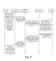
- Figure 9 is a flow chart of a method for a user handing over to a home NodeB provided by embodiment 6 of the present invention, and as shown in Figure 9 , the flow chart comprises the steps S901 to S908 as follows.
- Step S901 the macro base station judges to initiate a handover flow according to a measurement report reported by the user and sends a relocation request message to the mobility management unit of the core network, wherein the relocation request message carries information such as a target NodeB identifier.
- Step S902 after receiving the relocation request message, the mobility management unit of the core network sends the relocation request message to the target home NodeB gateway according to the target NodeB identifier information carried in the relocation request message.
- Step S903 by using an Iu connection identifier in the relocation request message as a temporary user identifier, the target home NodeB gateway generates a user context for the user and allocates a user context identifier, and sends the identifier to the target home NodeB via an identifier allocation message newly defined at an HNBAP layer.
- Step S904 the target home NodeB receives the HNBAP identifier allocation message and makes judgment according to the user context identifier in the message, and when the target home NodeB does not have the user context identifier, it stores the user context identifier as received and replies an identifier allocation acknowledgement message to the target home NodeB gateway.
- Step S905 after receiving the identifier allocation acknowledgement message, the target home NodeB gateway encapsulates the relocation request message in an RUA connection message and sends the RUA connection message to the target home NodeB.
- the RUA connection message carries a user context identifier already allocated for distinguishing the message.
- Step S906 the target home NodeB receives the RUA connection message, and encapsulates a relocation request acknowledgement message in an RUA direct transfer message after handover preparation has been completed and then sends the RUA direct transfer message to the target home NodeB gateway.
- the RUA direct transfer message carries a user context identifier already allocated for distinguishing the message.
- Step S907 the target home NodeB gateway receives the RUA direct transfer message, and sends the relocation request acknowledgement message to the mobility management unit of the core network to notify that handover preparation at the target side has been completed.
- Step S908 the mobility management unit of the core network triggers the macro base station via a relocation command to initiate a synchronization process from the user to the target home NodeB.
- Embodiments 7-12 are implementation manners of a user handing over from a source home NodeB to a target home NodeB.
- Figure 10 is a flow chart of a method for a user handing over to a home NodeB provided by embodiment 7 of the present invention, and as shown in Figure 10 , the flow chart comprises the steps S1001 to S 1008 as follows.
- Step S1001 a source home NodeB judges to initiate a handover flow according to a measurement report reported by the user and sends an RUA direct transfer message to a source home NodeB gateway, wherein the RUA direct transfer message encapsulates an RANAP message therein which contains a relocation request message therein.
- the relocation request message carries information such as a target NodeB identifier.
- Step S1002 the source home NodeB gateway receives the RUA direct transfer message, and sends the relocation request message therein to the mobility management unit of the core network.
- Step S 1003 after receiving the relocation request message, the mobility management unit of the core network makes judgment according to the target NodeB identifier information carried in the relocation request message, and if it finds that a target NodeB to be handed over to is a home NodeB, it carries the permanent identifier IMSI of the user in the relocation request message sent to the target home NodeB gateway.
- Step S 1004 the target home NodeB gateway performs search according to the user permanent identifier IMSI in the relocation request message, if it finds that the user has not performed registration, it generates a user context for the user and allocates a user context identifier, encapsulates the user context identifier in an RUA connection message together with the relocation request message and sends the RUA connection message to the target home NodeB.
- Step S 1005 the target home NodeB receives the RUA connection message and makes judgment according to the message, and when the target home NodeB does not have the user context identifier, it stores the user context identifier as received and replies a relocation request acknowledgement message.
- the relocation request acknowledgement message as replied is encapsulated in an RUA direct transfer message which also carries the user context identifier to distinguish the corresponding relationship between the message and the user.
- Step S 1006 the target home NodeB gateway receives the RUA direct transfer message and sends the relocation request acknowledgement message to the mobility management unit of the core network to notify that handover preparation at the target side has been completed.
- Step S 1007 the mobility management unit of the core network sends a relocation command to the source home NodeB gateway.
- Step S 1008 the source home NodeB gateway encapsulates the relocation command message as received in the RUA direct transfer message, and sends the message to the source home NodeB to trigger the source home NodeB to initiate a synchronization process from the user to the target home NodeB.
- Figure 11 is a flow chart of a method for a user handing over to a home NodeB provided by embodiment 8 of the present invention, and as shown in Figure 11 , the flow chart comprises the steps S1101 to S 1108 as follows.
- Step S1101 a source home NodeB judges to initiate a handover flow according to a measurement report reported by the user, and when the source home NodeB is able to judge that a target NodeB to be handed over to is a home NodeB according to the configuration information of the target NodeB to be handed over to, it adds the permanent identifier IMSI of the user in a relocation request message in an RUA direct transfer message sent to a source home NodeB gateway.
- the relocation request message also carries information such as a target NodeB identifier.
- Step S 1102 the source home NodeB gateway receives the RUA direct transfer message, and sends the relocation request message therein to the mobility management unit of the core network.
- Step S 1103 after receiving the relocation request message, the mobility management unit of the core network sends the relocation request message to the target home NodeB gateway.
- Step S 1104 the target home NodeB gateway performs search according to the user permanent identifier IMSI in the relocation request message, if it finds that the user has not performed registration, it generates a user context for the user and allocates a user context identifier, encapsulates the user context identifier in an RUA connection message together with the relocation request message and sends the RUA connection message to the target home NodeB.
- Step S 1105 the target home NodeB receives the RUA connection message and makes judgment according to the message, and when the target home NodeB does not have the user context identifier, it stores the user context identifier as received and replies a relocation request acknowledgement message.
- the relocation request acknowledgement message as replied is encapsulated in an RUA direct transfer message which also carries the user context identifier to distinguish the corresponding relationship between the message and the user.
- Step S1106 the target home NodeB gateway receives the RUA direct transfer message and sends the relocation request acknowledgement message to the mobility management unit of the core network to notify that handover preparation at the target side has been completed.
- Step S 1107 the mobility management unit of the core network sends a relocation command to the source home NodeB gateway.
- Step S1108 the source home NodeB gateway encapsulates the relocation command message as received in the RUA direct transfer message, and sends the message to the source home NodeB to trigger the source home NodeB to initiate a synchronization process from the user to the target home NodeB.
- Figure 12 is a flow chart of a method for a user handing over to a home NodeB provided by embodiment 9 of the present invention, and as shown in Figure 12 , the flow chart comprises the steps S1201 to S 1208 as follows.
- Step S1201 a source home NodeB judges to initiate a handover flow according to a measurement report reported by the user and sends an RUA direct transfer message to a source home NodeB gateway, wherein the RUA direct transfer message encapsulates therein an RANAP message which contains therein a relocation request message.
- the relocation request message carries information such as a target NodeB identifier.
- Step S1202 the source home NodeB gateway receives the RUA direct transfer message, and sends the relocation request message therein to the mobility management unit of the core network.
- Step S1203 after receiving the relocation request message, the mobility management unit of the core network sends the relocation request message to the target home NodeB gateway according to the target NodeB identifier information carried in the relocation request message.
- Step S1204 by using an Iu connection identifier in the relocation request message as a temporary user identifier, the target home NodeB gateway generates a user context for the user and allocates a user context identifier, encapsulates the user context identifier in an RUA connection message together with the relocation request message and sends the RUA connection message to the target home NodeB.
- Step S1205 the target home NodeB receives the RUA connection message and makes judgment according to the message, and when the target home NodeB does not have the user context identifier, it stores the user context identifier as received and replies a relocation request acknowledgement message.
- the relocation request acknowledgement message as replied is encapsulated in an RUA direct transfer message which also carries the user context identifier to distinguish the corresponding relationship between the message and the user.
- Step S 1206 the target home NodeB gateway receives the RUA direct transfer message and sends the relocation request acknowledgement message to the mobility management unit of the core network to notify that handover preparation at the target side has been completed.
- Step S1207 the mobility management unit of the core network sends a relocation command to the source home NodeB gateway.
- Step S1208 the source home NodeB gateway encapsulates the relocation command message as received in the RUA direct transfer message, and sends the message to the source home NodeB to trigger the source home NodeB to initiate a synchronization process from the user to the target home NodeB.
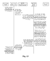
- Figure 13 is a flow chart of a method for a user handing over to a home NodeB provided by embodiment 10 of the present invention, and as shown in Figure 13 , the flow chart comprises the steps S1301 to S 1310 as follows.
- Step S1301 a source home NodeB judges to initiate a handover flow according to a measurement report reported by the user and sends an RUA direct transfer message to a source home NodeB gateway, wherein the RUA direct transfer message encapsulates therein an RANAP message which contains therein a relocation request message.
- the relocation request message carries information such as a target NodeB identifier.
- Step S1302 the source home NodeB gateway receives the RUA direct transfer message, and sends the relocation request message therein to the mobility management unit of the core network.
- Step S1303 after receiving the relocation request message, the mobility management unit of the core network makes judgment according to the target NodeB identifier information carried in the relocation request message, and if it finds that a target NodeB to be handed over to is a home NodeB, it carries the permanent identifier IMSI of the user in the relocation request message sent to the home NodeB gateway.
- Step S1304 the target home NodeB gateway performs search according to the user permanent identifier IMSI in the relocation request message, if it finds that the user has not performed registration, it generates a user context for the user and allocates a user context identifier, and sends the identifier to the target home NodeB via an identifier allocation message newly defined at an HNBAP layer.
- Step S1305 the target home NodeB receives the HNBAP identifier allocation message and makes judgment according to the user context identifier in the message, and when the target home NodeB does not have the user context identifier, it stores the user context identifier as received and replies an identifier allocation acknowledgement message to the target home NodeB gateway.
- Step S 1306 after receiving the identifier allocation acknowledgement message, the target home NodeB gateway encapsulates the relocation request message in an RUA connection message and sends the RUA connection message to the target home NodeB.
- the RUA connection message carries a user context identifier already allocated for distinguishing the message.
- Step S1307 the target home NodeB receives the RUA connection message, and encapsulates a relocation request acknowledgement message in an RUA direct transfer message after handover preparation has been completed and then sends the RUA direct transfer message to the target home NodeB gateway.
- the RUA direct transfer message carries a user context identifier already allocated for distinguishing the message.
- Step S1308 the target home NodeB gateway sends the relocation request acknowledgement message to the mobility management unit of the core network to notify that handover preparation at the target side has been completed.
- Step S1309 the mobility management unit of the core network sends a relocation command to the source home NodeB gateway.
- Step S 1310 the source home NodeB gateway encapsulates the relocation command message as received in the RUA direct transfer message, and sends the message to the source home NodeB to trigger the source home NodeB to initiate a synchronization process from the user to the target home NodeB.
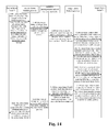
- Figure 14 is a flow chart of a method for a user handing over to a home NodeB provided by embodiment 11 of the present invention, and as shown in Figure 14 , the flow chart comprises the steps S1401 to S 14 10 as follows.
- Step S1401 a source home NodeB judges to initiate a handover flow according to a measurement report reported by the user, and when the source home NodeB is able to judge that a target NodeB to be handed over to is a home NodeB according to the configuration information of the target NodeB to be handed over to, it adds the permanent identifier IMSI of the user in a relocation request message in an RUA direct transfer message sent to a source home NodeB gateway.
- the relocation request message also carries information such as a target NodeB identifier.
- Step S1402 the source home NodeB gateway receives the RUA direct transfer message, and sends the relocation request message therein to the mobility management unit of the core network.
- Step S1403 after receiving the relocation request message, the mobility management unit of the core network sends the relocation request message to the target home NodeB gateway.
- Step S 1404 the target home NodeB gateway performs search according to the user permanent identifier IMSI in the relocation request message, if it finds that the user has not performed registration, it generates a user context for the user and allocates a user context identifier, and sends the identifier to the target home NodeB via an identifer allocation message newly defined at an HNBAP layer.
- Step S1405 the target home NodeB receives the HNBAP identifier allocation message and makes judgment according to the user context identifier in the message, and when the target home NodeB does not have the user context identifier, it stores the user context identifier as received and replies an identifier allocation acknowledgement message to the target home NodeB gateway.
- Step S 1406 after receiving the identifier allocation acknowledgement message, the target home NodeB gateway encapsulates the relocation request message in an RUA connection message and sends the RUA connection message to the target home NodeB.
- the RUA connection message carries a user context identifier already allocated for distinguishing the message.
- Step S 1407 the target home NodeB receives the RUA connection message, and encapsulates a relocation request acknowledgement message in an RUA direct transfer message after handover preparation has been completed and then sends the RUA direct transfer message to the target home NodeB gateway.
- the RUA direct transfer message carries a user context identifier already allocated for distinguishing the message.
- Step S1408 the target home NodeB gateway sends the relocation request acknowledgement message to the mobility management unit of the core network to notify that handover preparation at the target side has been completed.
- Step S1409 the mobility management unit of the core network sends a relocation command to the source home NodeB gateway.
- Step S1410 the source home NodeB gateway encapsulates the relocation command message as received in the RUA direct transfer message, and sends the message to the source home NodeB to trigger the source home NodeB to initiate a synchronization process from the user to the target home NodeB.
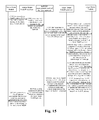
- Figure 15 is a flow chart of a method for a user handing over to a home NodeB provided by embodiment 12 of the present invention, and as shown in Figure 15 , the flow chart comprises the steps S 1501 to S1510 as follows.
- Step S1501 a source home NodeB judges to initiate a handover flow according to a measurement report reported by the user and sends an RUA direct transfer message to a source home NodeB gateway, wherein the RUA direct transfer message encapsulates therein an RANAP message which contains therein a relocation request message.
- the relocation request message carries information such as a target NodeB identifier.
- Step S1502 the source home NodeB gateway receives the RUA direct transfer message, and sends the relocation request message therein to the mobility management unit of the core network.
- Step S1503 after receiving the relocation request message, the mobility management unit of the core network sends the relocation request message to the target home NodeB gateway according to the target NodeB identifier information carried in the relocation request message.
- Step S1504 by using an Iu connection identifier in the relocation request message as a temporary user identifier, the target home NodeB gateway generates a user context for the user and allocates a user context identifier, and sends the identifier to the target home NodeB via an identifer allocation message newly defined at an HNBAP layer.
- Step S1505 the target home NodeB receives the HNBAP identifier allocation message and makes judgment according to the user context identifier in the message, and when the target home NodeB does not have the user context identifier, it stores the user context identifier as received and replies an identifier allocation acknowledgement message to the target home NodeB gateway.
- Step S 1506 after receiving the identifier allocation acknowledgement message, the target home NodeB gateway encapsulates the relocation request message in an RUA connection message and sends the RUA connection message to the target home NodeB.
- the RUA connection message carries a user context identifier already allocated for distinguishing the message.
- Step S1507 the target home NodeB receives the RUA connection message, and encapsulates a relocation request acknowledgement message in an RUA direct transfer message after handover preparation has been completed and then sends the RUA connection message to the target home NodeB gateway.
- the RUA direct transfer message carries a user context identifier already allocated for distinguishing the message.
- Step S1508 the target home NodeB gateway sends the relocation request acknowledgement message to the mobility management unit of the core network to notify that handover preparation at the target side has been completed.
- Step S1509 the mobility management unit of the core network sends a relocation command to the source home NodeB gateway.
- Step S 1510 the source home NodeB gateway encapsulates the relocation command message as received in the RUA direct transfer message, and sends the message to the source home NodeB to trigger the source home NodeB to initiate a synchronization process from the user to the target home NodeB.
- the above method described in the embodiments of the present invention successfully solves the following problem: when a user performs cell handover, if a target NodeB to be handed over to is a home NodeB, signaling messages between the home NodeB and a home NodeB gateway cannot be corresponded as the home NodeB gateway lacks a user context identifier, and thus the handover procedure cannot be successfully performed.
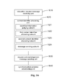
- Figure 16 is a block diagram of the structure of an apparatus for a user handing over to a home NodeB provided by an embodiment of the present invention, and as shown in Figure 16 , the apparatus comprises: a relocation request message receiving unit 1610, a context identifier allocating unit 1620 and a request acknowledgement message sending unit 1630.
- the relocation request message receiving unit 1610 is configured to receive , when a user initiates a handover procedure from a source NodeB to a target home NodeB, a relocation request message sent from a mobility management unit of the core network to which the source NodeB belongs;
- the context identifier allocating unit 1620 is configured to generate a user context for the user according to the relocation request message received by the relocation reuqest message receiving unit 1610, allocate a user context identifier for the user context, and send the user context identifier and the relocation request message to the target home NodeB for processing;
- the request acknowledgement message sending unit 1630 is configured to send a relocation request acknowledgement message to the mobility management unit of the core network when the relocation request acknowledgement message replied by the target home NodeB is received.
- the context identifier allocating unit 1620 further comprises: an identifier information judging subunit 1621, the first context identifier allocating subunit 1622, the second context identifier allocating subunit 1623 and a message sending subunit 1624.
- the identifier information judging subunit 1621 is configured to perform judgment according to the relocation request message sent from the relocation request message sending unit 1610, trigger the first context identifier allocating subunit 1622 when the relocation request message carries a user permanent identifier, and trigger the second context identifier allocating subunit 1623 when the relocation request message does not carry a user permanent identifier;
- the first context identifier allocating subunit 1622 is configured to perform search according to the user permanent identifier in the relocation request message, and generate the user context for the user if the user has not performed registration and allocate the user context identifier for the user context;
- the second context identifier allocating subunit 1623 is configured to generate the user context for the user by using an Iu connection identifier in the relocation request message as a temporary user identifier and allocate the user context identifier for the user context;
- the message sending subunit 1624 is configured to send the user context identifier and the relocation request message to the target home NodeB for processing.
- the apparatus provided by the present invention further comprises:
- the apparatus provided by the present invention solves the following problem: when a user performs cell handover, if a target NodeB to be handed over to is a home NodeB, signaling messages between the home NodeB and a home NodeB gateway cannot be corresponded as the home NodeB gateway lacks a user context identifier, and thus the handover procedure cannot be successfully performed.
Landscapes
- Engineering & Computer Science (AREA)
- Computer Networks & Wireless Communication (AREA)
- Signal Processing (AREA)
- Mobile Radio Communication Systems (AREA)
Claims (11)
- Verfahren für eine Benutzerübergabe an einen Heim-NodeB, dadurch gekennzeichnet, dass es die folgenden Schritte umfasst:A. wenn der Benutzer einen Übergabevorgang von einem Quell-NodeB zu einem Ziel-Heim-NodeB einleitet, empfängt ein Ziel-Heim-NodeB-Gateway eine Standortwechselanforderungsanfrage von einer Mobilitätsverwaltungseinheit eines Kernnetzes;B. das Ziel-Heim-NodeB-Gateway erzeugt einen Benutzerkontext für den Benutzer gemäß der Standortwechselanforderungsnachricht, stellt ein Benutzerkontextidentifizierungszeichen für den Benutzerkontext bereit, und sendet das Benutzerkontextidentifizierungszeichen und die Positionswechselanforderungsnachricht zu dem Ziel-Heim-NodeB; undC. wenn eine von dem Ziel-Heim-NodeB erwiderte Standortwechselanforderungsbestätigungsnachricht empfangen wird, sendet das Ziel-Heim-NodeB-Gateway die Standortwechselanforderungsbestätigungsnachricht zu der Mobilitätsverwaltungseinheit des Kernnetzes.
- Verfahren nach Anspruch 1, dadurch gekennzeichnet, dass der Schritt A umfasst:der Quelle-NodeB leitet den Übergabevorgang gemäß einem von dem Benutzer berichteten Messbericht ein;wenn der Quell-NodeB eine Makro-Basisstation ist, sendet der Quell-NodeB eine Standortwechselanforderungsnachricht direkt zu der Mobilitätsverwaltungseinheit des Kernnetzes, und wenn der Quell-NodeB ein Heim-NodeB ist, sendet der Quell-NodeB eine Standortwechselanforderungsnachricht über ein Heim-NodeB-Gateway zu der Mobilitätsverwaltungseinheit des Kernnetzes; unddie Mobilitätsverwaltungseinheit des Kernnetzes sendet die Standortwechselanforderungsnachricht, welche ein von der Mobilitätsverwaltungseinheit des Kernnetzes hinzugefügtes Benutzer-permanentes Identifizierungszeichen trägt, zu dem Ziel-Heim-NodeB-Gateway gemäß der Standortwechselanforderungsnachricht.
- Verfahren nach Anspruch 1, dadurch gekennzeichnet, dass der Schritt A umfasst:der Quell-NodeB leitet den Übergabevorgang gemäß einem von dem Benutzer berichteten Messbericht ein;wenn der Quell-NodeB eine Makro-Basisstation ist, sendet der Quell-NodeB eine Standortwechselanforderungsnachricht direkt zu der Mobilitätsverwaltungseinheit des Kernnetzes, und wenn der Quell-NodeB ein Heim-NodeB ist, sendet der Quell-NodeB eine Standortwechselanforderungsnachricht über ein Heim-NodeB-Gateway zu der Mobilitätsverwaltungseinheit des Kernnetzes, wobei die Standortwechselanforderungsnachricht ein Benutzer-permanentes Identifizierungszeichen trägt, welches von dem Quell-NodeB hinzugefügt wurde; unddie Mobilitätsverwaltungseinheit des Kernnetzes sendet die Standortwechselanforderungsnachricht zu dem Ziel-Heim-NodeB-Gateway gemäß der empfangenen Standortwechselanforderungsnachricht.
- Verfahren nach Anspruch 2 oder 3, dadurch gekennzeichnet, dass im Schritt B der Schritt des Erzeugens eines Benutzerkontexts für den Benutzer gemäß der Standortwechselanforderungsnachricht und das Bereitstellen eines Benutzerkontextidentifizierungszeichens für den Benutzerkontext umfasst:wenn die Standortwechselanforderungsnachricht das Benutzer-permanente Identifizierungszeichen trägt, wird gemäß dem Benutzer-permanentem Identifizierungszeichen in der Standortwechselanforderungsnachricht nachgeschaut, ob der Benutzer eine Registrierung nicht ausgeführt hat, und dann wird der Benutzerkontext für den Benutzer erzeugt, und das Benutzerkontextidentifizierungszeichnen für den Benutzerkontext bereitgestellt.
- Verfahren nach Anspruch 1, dadurch gekennzeichnet, dass der Schritt A umfasst:der Quell-NodeB leitet den Übergabevorgang gemäß einem von dem Benutzer berichteten Messbericht ein;wenn der Quell-NodeB eine Makro-Basisstation ist, sendet der Quell-NodeB eine Standortwechselanforderungsnachricht direkt zu der Mobilitätsverwaltungseinheit des Kernnetzes, und wenn der Quell-NodeB ein Heim-NodeB ist, sendet der Quell-NodeB eine Standortwechselanforderungsnachricht über ein Heim-NodeB-Gateway zu der Mobilitätsverwaltungseinheit des Kernnetzes; unddie Mobilitätsverwaltungseinheit des Kernnetzes sendet die Positionswechselanforderungsnachricht zu dem Ziel-Heim-NodeB-Gateway gemäß der empfangenen Standortwechselanforderungsnachricht.
- Verfahren nach Anspruch 5, dadurch gekennzeichnet, dass im Schritt B der Schritt des Erzeugens eines Benutzerkontexts für den Benutzer gemäß der Standortwechselanforderungsnachricht und des Bereitstellens eines Benutzerkontextidentifizierungszeichens für den Benutzerkontext umfasst:wenn die Standortwechselanforderungsnachricht kein Benutzer-permanentes Identifizierungszeichen trägt, wird der Benutzerkontext für den Benutzer durch Verwenden eines Iu-Verbindungsidentifizierungszeichens in der Standortwechselanforderungsnachricht als ein temporäres Benutzeridentifizierungszeichen erzeugt und das Benutzerkontextidentifizierungszeichens für den Benutzerkontext bereitgestellt.
- Verfahren nach Anspruch 1, 2, 3 oder 5, dadurch gekennzeichnet, dass im Schritt B der Schritt des Sendens des Benutzerkontextidentifizierungszeichens und der Standortwechselanforderungsnachricht zu dem Ziel-Heim-NodeB umfasst:das Ziel-Heim-NodeB-Gateway kapselt die Benutzerkontextidentifizierungszeicheninformation und die Standortwechselanforderungsnachricht in einer Verbindungsnachricht für eine Funkzugriffsnetzanwendungsteilbenutzeranpassung, RUA, ein, unddie RUA-Verbindungsnachricht wird zu dem Ziel-Heim-NodeB gesendet; oderdas Ziel-Heim-NodeB-Gateway sendet die Benutzerkontextidentifizierungszeicheninformation zu dem Ziel-Heim-NodeB über eine Identifizierungszeichenbereitstellungsinformation, welche in einer Heim-NodeB-Anwendungsprotkollschicht neu definiert ist, kapselt die Standortwechselanforderungsnachricht in einer RUA-Verbindungsnachricht ein, nachdem eine von dem Ziel-Heim-NodeB erwiderte Identifizierungszeichenbereitstellungsbestätigungsnachricht empfangen wurde, und sendet dann die RUA-Verbindungsnachricht zu dem Ziel-Heim-NodeB.
- Verfahren nach Anspruch 1, dadurch gekennzeichnet, dass nach dem Schritt C das Verfahren ferner umfasst:die Mobilitätsverwaltungseinheit des Kernnetzes sendet einen Standortwechselbefehl, um den Quell-NodeB zu veranlassen, einen Synchronisationsprozess von dem Benutzer zu dem Ziel-Heim-NodeB einzuleiten.
- Vorrichtung für eine Benutzerübergabe zu einem Heim-NodeB, dadurch gekennzeichnet, dass sie umfasst:eine Standortwechselanforderungsnachrichtempfangseinheit (1610), welche ausgestaltet ist, wenn ein Benutzer einen Übergabevorgang von einem Quell-NodeB zu einem Ziel-Heim-NodeB einleitet, eine Standortwechselanforderungsnachricht zu empfangen, welche von einer Mobilitätsverwaltungseinheit eines Kernnetzes gesendet wurde, zu welchem der Quell-NodeB gehört;eine Kontextidentifizierungszeichenbereitstellungseinheit (1620), welche ausgestaltet ist, einen Benutzerkontext für den Benutzer gemäß der Standortwechselanforderungsnachricht, welche von der Standortwechselanforderungsnachrichtempfangseinheit (1610) empfangen wurde, zu erzeugen, ein Benutzerkontextidentifizierungszeichen für den Benutzerkontext bereitzustellen, und das Benutzerkontextidentifizierungszeichen und die Standortwechselanforderungsnachricht zu dem Ziel-Heim-NodeB für eine Verarbeitung zu senden; undeine Anforderungsbestätigungsnachrichtsendeeinheit (1630), welche ausgestaltet ist, eine Standortwechselanforderungsbestätigungsnachricht zu der Mobilitätsverwaltungseinheit des Kernnetzes zu senden, wenn die von dem Ziel-Heim-NodeB rückgemeldete Standortwechselanforderungsbestätigungsnachricht empfangen wird.
- Vorrichtung nach Anspruch 9, dadurch gekennzeichnet, dass die Kontextidentifizierungszeichenbereitstellungseinheit ferner umfasst: eine Identifizierungszeicheninformationsbeurteilungsteileinheit (1621), eine erste Kontextidentifizierungszeichenbereitstellungsteileinheit (1622), eine zweite Kontextidentifizierungszeichenbereitstellungsteileinheit (1623) und eine Nachrichtensendeteileinheit (1624), wobei
die Identifizierungszeicheninformationsbeurteilungsteileinheit (1621) ausgestaltet ist, eine Beurteilung gemäß der von der Standortwechselanforderungsnachrichtsendeeinheit gesendete Standortwechselanforderungsnachricht auszuführen, die erste Kontextidentifizierungszeichenbereitstellungsteileinheit (1622) anzusteuern, wenn die Standortwechselanforderungsnachricht ein Benutzer-permanentes Identifizierungszeichen trägt, und die zweite Kontextidentifizierungszeichenbereitstellungsteileinheit (1623) anzusteuern, wenn die Standortwechselanforderungsnachricht kein Benutzer-permanentes Identifizierungszeichen trägt;
die erste Kontextidentifizierungsbereitstellungsteileinheit (1622) ausgestaltet ist, eine Suche gemäß dem Benutzer-permanentem Identifizierungszeichen in der Standortwechselanforderungsnachricht auszuführen und den Benutzerkontext für den Benutzer zu erzeugen, wenn der Benutzer keine Registrierung durchgeführt hat, und das Benutzerkontextidentifizierungszeichen für den Benutzerkontext bereitzustellen;
die zweite Kontextidentifizierungszeichenbereitstellungsteileinheit (1623) ausgestaltet ist, den Benutzerkontext für den Benutzer zu erzeugen, indem ein Iu-Verbindungsidentifizierungszeichen in der Standortwechselanforderungsnachricht als ein temporäres Benutzeridentifizierungszeichen benutzt wird, und das Benutzerkontextidentifizierungszeichen für den Benutzerkontext bereitzustellen; und
die Nachrichtensendeteileinheit (1624) ausgestaltet ist, das Benutzerkontextidentifizierungszeichen und die Standortwechselanforderungsnachricht zu dem Ziel-Heim-NodeB für eine Verarbeitung zu senden. - Vorrichtung nach Anspruch 9, dadurch gekennzeichnet, dass die Vorrichtung ferner umfasst:eine Synchronisationsprozesseinrichtungseinheit (1640), welche ausgestaltet ist, einen Standortwechselbefehl über die Mobilitätsverwaltungseinheit des Kernnetzes zu senden, um den Quell-NodeB zu veranlassen, einen Synchronisationsprozess von dem Benutzer zu dem Ziel-Heim-NodeB einzuleiten.
Applications Claiming Priority (2)
| Application Number | Priority Date | Filing Date | Title |
|---|---|---|---|
| CN200910009454A CN101815329B (zh) | 2009-02-25 | 2009-02-25 | 一种用户切换到家用基站的方法和装置 |
| PCT/CN2009/073624 WO2010096977A1 (zh) | 2009-02-25 | 2009-08-28 | 一种用户切换到家用基站的方法和装置 |
Publications (3)
| Publication Number | Publication Date |
|---|---|
| EP2403293A1 EP2403293A1 (de) | 2012-01-04 |
| EP2403293A4 EP2403293A4 (de) | 2013-11-27 |
| EP2403293B1 true EP2403293B1 (de) | 2015-02-25 |
Family
ID=42622412
Family Applications (1)
| Application Number | Title | Priority Date | Filing Date |
|---|---|---|---|
| EP09840645.7A Active EP2403293B1 (de) | 2009-02-25 | 2009-08-28 | Verfahren und vorrichtung zur benutzerübergabe an einen heimatknoten |
Country Status (5)
| Country | Link |
|---|---|
| US (1) | US8611308B2 (de) |
| EP (1) | EP2403293B1 (de) |
| CN (1) | CN101815329B (de) |
| ES (1) | ES2535408T3 (de) |
| WO (1) | WO2010096977A1 (de) |
Families Citing this family (8)
| Publication number | Priority date | Publication date | Assignee | Title |
|---|---|---|---|---|
| CN101815329B (zh) * | 2009-02-25 | 2012-09-05 | 中兴通讯股份有限公司 | 一种用户切换到家用基站的方法和装置 |
| EP2424300A4 (de) * | 2009-04-20 | 2015-05-13 | Nec Corp | Gatewayvorrichtung, kommunikationssteuerungsverfahren und nichttransitorisches computerlesbares medium mit darauf gespeichertem steuerprogramm |
| WO2015018074A1 (en) * | 2013-08-09 | 2015-02-12 | Nokia Solutions And Networks Oy | Methods and apparatus |
| WO2016119267A1 (zh) * | 2015-01-31 | 2016-08-04 | 华为技术有限公司 | 一种用户设备迁移方法、核心网设备、接入网设备及系统 |
| CN106162866A (zh) * | 2015-04-21 | 2016-11-23 | 中兴通讯股份有限公司 | 一种重定位处理方法、装置及无线网络控制器 |
| WO2017127102A1 (en) * | 2016-01-22 | 2017-07-27 | Nokia Solutions And Networks Oy | Application relocation between clouds |
| WO2018170744A1 (en) * | 2017-03-21 | 2018-09-27 | Motorola Mobility Llc | Ue context storage and context identification |
| CN109526010B (zh) * | 2019-01-02 | 2022-03-15 | 广州汇智通信技术有限公司 | 一种通信系统切换优化方法和系统 |
Family Cites Families (10)
| Publication number | Priority date | Publication date | Assignee | Title |
|---|---|---|---|---|
| CA2655954C (en) * | 2006-06-20 | 2013-06-18 | Interdigital Technology Corporation | Methods and system for performing handover in a wireless communication system |
| CA2677072C (en) * | 2007-03-21 | 2014-01-21 | Nokia Corporation | Method, apparatus and computer program product for handover failure recovery |
| EP2138005A2 (de) * | 2007-03-21 | 2009-12-30 | Nokia Corporation | Verfahren, vorrichtung und computerprogrammprodukt zur datenweiterleitung beim handover |
| KR101606313B1 (ko) * | 2007-04-30 | 2016-03-24 | 인터디지탈 테크날러지 코포레이션 | 홈 노드 b에서의 이동성 절차 및 차별화된 과금 |
| CN101330737B (zh) * | 2007-06-21 | 2013-02-27 | 华为技术有限公司 | 接入室内基站的方法、网络设备以及用户设备 |
| CN101123577B (zh) * | 2007-08-24 | 2010-05-26 | 中兴通讯股份有限公司 | 一种全球微波接入互通终端进行基站切换的方法 |
| CN101287294B (zh) * | 2008-06-11 | 2012-07-04 | 中兴通讯股份有限公司 | 移动管理实体、终端转移方法和系统 |
| CN101815329B (zh) * | 2009-02-25 | 2012-09-05 | 中兴通讯股份有限公司 | 一种用户切换到家用基站的方法和装置 |
| KR20110111790A (ko) * | 2010-04-05 | 2011-10-12 | 주식회사 팬택 | 다중 요소 반송파를 사용하는 무선 통신 시스템에서의 핸드오버 시 요소반송파 정보 시그널링 방법 및 장치 |
| KR102198740B1 (ko) * | 2011-07-01 | 2021-01-06 | 인터디지탈 패튼 홀딩스, 인크 | 로컬 ip 액세스 - lipa - 모빌리티를 지원하기 위한 방법 및 장치 |
-
2009
- 2009-02-25 CN CN200910009454A patent/CN101815329B/zh active Active
- 2009-08-28 WO PCT/CN2009/073624 patent/WO2010096977A1/zh not_active Ceased
- 2009-08-28 ES ES09840645.7T patent/ES2535408T3/es active Active
- 2009-08-28 US US13/203,479 patent/US8611308B2/en active Active
- 2009-08-28 EP EP09840645.7A patent/EP2403293B1/de active Active
Also Published As
| Publication number | Publication date |
|---|---|
| EP2403293A4 (de) | 2013-11-27 |
| WO2010096977A1 (zh) | 2010-09-02 |
| EP2403293A1 (de) | 2012-01-04 |
| ES2535408T3 (es) | 2015-05-11 |
| US8611308B2 (en) | 2013-12-17 |
| US20110305221A1 (en) | 2011-12-15 |
| CN101815329B (zh) | 2012-09-05 |
| CN101815329A (zh) | 2010-08-25 |
Similar Documents
| Publication | Publication Date | Title |
|---|---|---|
| CN102238668B (zh) | 一种通过网关进行x2切换的方法 | |
| KR102859304B1 (ko) | 핸드오버를 지원하는 방법 및 상응하는 장치 | |
| CN112040567B (zh) | 一种恢复rrc连接的方法及装置、计算机存储介质 | |
| EP2403293A1 (de) | Verfahren und vorrichtung zur benutzerübergabe an einen heimatknoten | |
| CN106576107B (zh) | 无线通信方法、装置和系统 | |
| CN102123460B (zh) | 集群移动通信系统中实现组呼业务切换的方法 | |
| JP5021772B2 (ja) | トラッキングエリアの更新或いは切替プロセスにおいてリソースが誤ってリリースされることを防ぐ方法 | |
| CN110062466B (zh) | 通信系统、无线电站、核心网络、及其方法 | |
| CN105409285B (zh) | 一种控制承载切换的设备和控制方法 | |
| CN101175304A (zh) | 基于中继系统的切换方法 | |
| WO2016048573A1 (en) | Smooth ue transfer within an evolved packet core | |
| CN105025465A (zh) | 用户终端位置上报方法、基站、移动管理实体及系统 | |
| CN106331200A (zh) | 一种节点间数据传输的方法、网关节点及节点 | |
| CN102111829B (zh) | 一种组呼被呼业务越区切换的方法 | |
| CN104380796A (zh) | 一种无默认承载的切换方法和设备 | |
| CN101784033B (zh) | 切换数据转发处理方法、装置和系统 | |
| CN104301954A (zh) | 切换方法、装置、基站和系统 | |
| CN106686666A (zh) | 一种网关信息更新的方法及装置 | |
| EP2448344A1 (de) | Verfahren und system zur zellaktualisierung | |
| CN101472260A (zh) | 移动性管理网元信息的删除方法和设备 | |
| CN106686622A (zh) | 一种网关信息更新方法及装置 | |
| WO2016107144A1 (zh) | 用户面路径的更新方法、装置及系统 | |
| CN112312495B (zh) | 一种支持在移动通信网络中切换的方法 | |
| CN103024838B (zh) | 一种支持中继节点服务网关重定位的方法 | |
| CN102378292B (zh) | 一种双模rnc内cs业务系统间切换的方法及装置 |
Legal Events
| Date | Code | Title | Description |
|---|---|---|---|
| PUAI | Public reference made under article 153(3) epc to a published international application that has entered the european phase |
Free format text: ORIGINAL CODE: 0009012 |
|
| 17P | Request for examination filed |
Effective date: 20110814 |
|
| AK | Designated contracting states |
Kind code of ref document: A1 Designated state(s): AT BE BG CH CY CZ DE DK EE ES FI FR GB GR HR HU IE IS IT LI LT LU LV MC MK MT NL NO PL PT RO SE SI SK SM TR |
|
| DAX | Request for extension of the european patent (deleted) | ||
| A4 | Supplementary search report drawn up and despatched |
Effective date: 20131030 |
|
| RIC1 | Information provided on ipc code assigned before grant |
Ipc: H04W 36/00 20090101AFI20131024BHEP |
|
| RIC1 | Information provided on ipc code assigned before grant |
Ipc: H04W 36/00 20090101AFI20131120BHEP |
|
| 17Q | First examination report despatched |
Effective date: 20140422 |
|
| GRAP | Despatch of communication of intention to grant a patent |
Free format text: ORIGINAL CODE: EPIDOSNIGR1 |
|
| INTG | Intention to grant announced |
Effective date: 20141009 |
|
| GRAS | Grant fee paid |
Free format text: ORIGINAL CODE: EPIDOSNIGR3 |
|
| GRAA | (expected) grant |
Free format text: ORIGINAL CODE: 0009210 |
|
| AK | Designated contracting states |
Kind code of ref document: B1 Designated state(s): AT BE BG CH CY CZ DE DK EE ES FI FR GB GR HR HU IE IS IT LI LT LU LV MC MK MT NL NO PL PT RO SE SI SK SM TR |
|
| REG | Reference to a national code |
Ref country code: GB Ref legal event code: FG4D |
|
| REG | Reference to a national code |
Ref country code: CH Ref legal event code: EP |
|
| REG | Reference to a national code |
Ref country code: IE Ref legal event code: FG4D |
|
| REG | Reference to a national code |
Ref country code: DE Ref legal event code: R096 Ref document number: 602009029684 Country of ref document: DE Effective date: 20150409 |
|
| REG | Reference to a national code |
Ref country code: AT Ref legal event code: REF Ref document number: 712895 Country of ref document: AT Kind code of ref document: T Effective date: 20150415 |
|
| REG | Reference to a national code |
Ref country code: ES Ref legal event code: FG2A Ref document number: 2535408 Country of ref document: ES Kind code of ref document: T3 Effective date: 20150511 |
|
| REG | Reference to a national code |
Ref country code: SE Ref legal event code: TRGR |
|
| REG | Reference to a national code |
Ref country code: AT Ref legal event code: MK05 Ref document number: 712895 Country of ref document: AT Kind code of ref document: T Effective date: 20150225 |
|
| REG | Reference to a national code |
Ref country code: LT Ref legal event code: MG4D |
|
| PG25 | Lapsed in a contracting state [announced via postgrant information from national office to epo] |
Ref country code: FI Free format text: LAPSE BECAUSE OF FAILURE TO SUBMIT A TRANSLATION OF THE DESCRIPTION OR TO PAY THE FEE WITHIN THE PRESCRIBED TIME-LIMIT Effective date: 20150225 Ref country code: NO Free format text: LAPSE BECAUSE OF FAILURE TO SUBMIT A TRANSLATION OF THE DESCRIPTION OR TO PAY THE FEE WITHIN THE PRESCRIBED TIME-LIMIT Effective date: 20150525 Ref country code: LT Free format text: LAPSE BECAUSE OF FAILURE TO SUBMIT A TRANSLATION OF THE DESCRIPTION OR TO PAY THE FEE WITHIN THE PRESCRIBED TIME-LIMIT Effective date: 20150225 Ref country code: HR Free format text: LAPSE BECAUSE OF FAILURE TO SUBMIT A TRANSLATION OF THE DESCRIPTION OR TO PAY THE FEE WITHIN THE PRESCRIBED TIME-LIMIT Effective date: 20150225 |
|
| PG25 | Lapsed in a contracting state [announced via postgrant information from national office to epo] |
Ref country code: AT Free format text: LAPSE BECAUSE OF FAILURE TO SUBMIT A TRANSLATION OF THE DESCRIPTION OR TO PAY THE FEE WITHIN THE PRESCRIBED TIME-LIMIT Effective date: 20150225 Ref country code: LV Free format text: LAPSE BECAUSE OF FAILURE TO SUBMIT A TRANSLATION OF THE DESCRIPTION OR TO PAY THE FEE WITHIN THE PRESCRIBED TIME-LIMIT Effective date: 20150225 Ref country code: GR Free format text: LAPSE BECAUSE OF FAILURE TO SUBMIT A TRANSLATION OF THE DESCRIPTION OR TO PAY THE FEE WITHIN THE PRESCRIBED TIME-LIMIT Effective date: 20150526 Ref country code: IS Free format text: LAPSE BECAUSE OF FAILURE TO SUBMIT A TRANSLATION OF THE DESCRIPTION OR TO PAY THE FEE WITHIN THE PRESCRIBED TIME-LIMIT Effective date: 20150625 |
|
| REG | Reference to a national code |
Ref country code: HU Ref legal event code: AG4A Ref document number: E024221 Country of ref document: HU |
|
| PG25 | Lapsed in a contracting state [announced via postgrant information from national office to epo] |
Ref country code: SK Free format text: LAPSE BECAUSE OF FAILURE TO SUBMIT A TRANSLATION OF THE DESCRIPTION OR TO PAY THE FEE WITHIN THE PRESCRIBED TIME-LIMIT Effective date: 20150225 Ref country code: DK Free format text: LAPSE BECAUSE OF FAILURE TO SUBMIT A TRANSLATION OF THE DESCRIPTION OR TO PAY THE FEE WITHIN THE PRESCRIBED TIME-LIMIT Effective date: 20150225 Ref country code: CZ Free format text: LAPSE BECAUSE OF FAILURE TO SUBMIT A TRANSLATION OF THE DESCRIPTION OR TO PAY THE FEE WITHIN THE PRESCRIBED TIME-LIMIT Effective date: 20150225 Ref country code: EE Free format text: LAPSE BECAUSE OF FAILURE TO SUBMIT A TRANSLATION OF THE DESCRIPTION OR TO PAY THE FEE WITHIN THE PRESCRIBED TIME-LIMIT Effective date: 20150225 Ref country code: RO Free format text: LAPSE BECAUSE OF FAILURE TO SUBMIT A TRANSLATION OF THE DESCRIPTION OR TO PAY THE FEE WITHIN THE PRESCRIBED TIME-LIMIT Effective date: 20150225 |
|
| REG | Reference to a national code |
Ref country code: DE Ref legal event code: R097 Ref document number: 602009029684 Country of ref document: DE |
|
| PG25 | Lapsed in a contracting state [announced via postgrant information from national office to epo] |
Ref country code: PL Free format text: LAPSE BECAUSE OF FAILURE TO SUBMIT A TRANSLATION OF THE DESCRIPTION OR TO PAY THE FEE WITHIN THE PRESCRIBED TIME-LIMIT Effective date: 20150225 |
|
| PLBE | No opposition filed within time limit |
Free format text: ORIGINAL CODE: 0009261 |
|
| STAA | Information on the status of an ep patent application or granted ep patent |
Free format text: STATUS: NO OPPOSITION FILED WITHIN TIME LIMIT |
|
| 26N | No opposition filed |
Effective date: 20151126 |
|
| PG25 | Lapsed in a contracting state [announced via postgrant information from national office to epo] |
Ref country code: SI Free format text: LAPSE BECAUSE OF FAILURE TO SUBMIT A TRANSLATION OF THE DESCRIPTION OR TO PAY THE FEE WITHIN THE PRESCRIBED TIME-LIMIT Effective date: 20150225 |
|
| PG25 | Lapsed in a contracting state [announced via postgrant information from national office to epo] |
Ref country code: LU Free format text: LAPSE BECAUSE OF FAILURE TO SUBMIT A TRANSLATION OF THE DESCRIPTION OR TO PAY THE FEE WITHIN THE PRESCRIBED TIME-LIMIT Effective date: 20150828 Ref country code: MC Free format text: LAPSE BECAUSE OF FAILURE TO SUBMIT A TRANSLATION OF THE DESCRIPTION OR TO PAY THE FEE WITHIN THE PRESCRIBED TIME-LIMIT Effective date: 20150225 |
|
| REG | Reference to a national code |
Ref country code: CH Ref legal event code: PL |
|
| PG25 | Lapsed in a contracting state [announced via postgrant information from national office to epo] |
Ref country code: CH Free format text: LAPSE BECAUSE OF NON-PAYMENT OF DUE FEES Effective date: 20150831 Ref country code: LI Free format text: LAPSE BECAUSE OF NON-PAYMENT OF DUE FEES Effective date: 20150831 |
|
| PG25 | Lapsed in a contracting state [announced via postgrant information from national office to epo] |
Ref country code: BE Free format text: LAPSE BECAUSE OF FAILURE TO SUBMIT A TRANSLATION OF THE DESCRIPTION OR TO PAY THE FEE WITHIN THE PRESCRIBED TIME-LIMIT Effective date: 20150225 |
|
| REG | Reference to a national code |
Ref country code: IE Ref legal event code: MM4A |
|
| REG | Reference to a national code |
Ref country code: FR Ref legal event code: PLFP Year of fee payment: 8 |
|
| PG25 | Lapsed in a contracting state [announced via postgrant information from national office to epo] |
Ref country code: IE Free format text: LAPSE BECAUSE OF NON-PAYMENT OF DUE FEES Effective date: 20150828 |
|
| PG25 | Lapsed in a contracting state [announced via postgrant information from national office to epo] |
Ref country code: MT Free format text: LAPSE BECAUSE OF FAILURE TO SUBMIT A TRANSLATION OF THE DESCRIPTION OR TO PAY THE FEE WITHIN THE PRESCRIBED TIME-LIMIT Effective date: 20150225 |
|
| PG25 | Lapsed in a contracting state [announced via postgrant information from national office to epo] |
Ref country code: BG Free format text: LAPSE BECAUSE OF FAILURE TO SUBMIT A TRANSLATION OF THE DESCRIPTION OR TO PAY THE FEE WITHIN THE PRESCRIBED TIME-LIMIT Effective date: 20150225 Ref country code: SM Free format text: LAPSE BECAUSE OF FAILURE TO SUBMIT A TRANSLATION OF THE DESCRIPTION OR TO PAY THE FEE WITHIN THE PRESCRIBED TIME-LIMIT Effective date: 20150225 |
|
| PG25 | Lapsed in a contracting state [announced via postgrant information from national office to epo] |
Ref country code: CY Free format text: LAPSE BECAUSE OF FAILURE TO SUBMIT A TRANSLATION OF THE DESCRIPTION OR TO PAY THE FEE WITHIN THE PRESCRIBED TIME-LIMIT Effective date: 20150225 |
|
| REG | Reference to a national code |
Ref country code: FR Ref legal event code: PLFP Year of fee payment: 9 |
|
| PG25 | Lapsed in a contracting state [announced via postgrant information from national office to epo] |
Ref country code: TR Free format text: LAPSE BECAUSE OF FAILURE TO SUBMIT A TRANSLATION OF THE DESCRIPTION OR TO PAY THE FEE WITHIN THE PRESCRIBED TIME-LIMIT Effective date: 20150225 |
|
| PG25 | Lapsed in a contracting state [announced via postgrant information from national office to epo] |
Ref country code: PT Free format text: LAPSE BECAUSE OF FAILURE TO SUBMIT A TRANSLATION OF THE DESCRIPTION OR TO PAY THE FEE WITHIN THE PRESCRIBED TIME-LIMIT Effective date: 20150225 Ref country code: MK Free format text: LAPSE BECAUSE OF FAILURE TO SUBMIT A TRANSLATION OF THE DESCRIPTION OR TO PAY THE FEE WITHIN THE PRESCRIBED TIME-LIMIT Effective date: 20150225 |
|
| REG | Reference to a national code |
Ref country code: FR Ref legal event code: PLFP Year of fee payment: 10 |
|
| PGFP | Annual fee paid to national office [announced via postgrant information from national office to epo] |
Ref country code: NL Payment date: 20250704 Year of fee payment: 17 |
|
| PGFP | Annual fee paid to national office [announced via postgrant information from national office to epo] |
Ref country code: HU Payment date: 20250728 Year of fee payment: 17 |
|
| PGFP | Annual fee paid to national office [announced via postgrant information from national office to epo] |
Ref country code: ES Payment date: 20250902 Year of fee payment: 17 |
|
| PGFP | Annual fee paid to national office [announced via postgrant information from national office to epo] |
Ref country code: DE Payment date: 20250702 Year of fee payment: 17 |
|
| PGFP | Annual fee paid to national office [announced via postgrant information from national office to epo] |
Ref country code: IT Payment date: 20250722 Year of fee payment: 17 |
|
| PGFP | Annual fee paid to national office [announced via postgrant information from national office to epo] |
Ref country code: GB Payment date: 20250703 Year of fee payment: 17 |
|
| PGFP | Annual fee paid to national office [announced via postgrant information from national office to epo] |
Ref country code: FR Payment date: 20250703 Year of fee payment: 17 |
|
| PGFP | Annual fee paid to national office [announced via postgrant information from national office to epo] |
Ref country code: SE Payment date: 20250702 Year of fee payment: 17 |