EP2403105A2 - Battery management systems for protecting batteries from fault conditions - Google Patents
Battery management systems for protecting batteries from fault conditions Download PDFInfo
- Publication number
- EP2403105A2 EP2403105A2 EP11168682A EP11168682A EP2403105A2 EP 2403105 A2 EP2403105 A2 EP 2403105A2 EP 11168682 A EP11168682 A EP 11168682A EP 11168682 A EP11168682 A EP 11168682A EP 2403105 A2 EP2403105 A2 EP 2403105A2
- Authority
- EP
- European Patent Office
- Prior art keywords
- battery
- battery cells
- time
- threshold
- difference
- Prior art date
- Legal status (The legal status is an assumption and is not a legal conclusion. Google has not performed a legal analysis and makes no representation as to the accuracy of the status listed.)
- Withdrawn
Links
Images


Classifications
-
- G—PHYSICS
- G01—MEASURING; TESTING
- G01R—MEASURING ELECTRIC VARIABLES; MEASURING MAGNETIC VARIABLES
- G01R31/00—Arrangements for testing electric properties; Arrangements for locating electric faults; Arrangements for electrical testing characterised by what is being tested not provided for elsewhere
- G01R31/36—Arrangements for testing, measuring or monitoring the electrical condition of accumulators or electric batteries, e.g. capacity or state of charge [SoC]
-
- B—PERFORMING OPERATIONS; TRANSPORTING
- B60—VEHICLES IN GENERAL
- B60L—PROPULSION OF ELECTRICALLY-PROPELLED VEHICLES; SUPPLYING ELECTRIC POWER FOR AUXILIARY EQUIPMENT OF ELECTRICALLY-PROPELLED VEHICLES; ELECTRODYNAMIC BRAKE SYSTEMS FOR VEHICLES IN GENERAL; MAGNETIC SUSPENSION OR LEVITATION FOR VEHICLES; MONITORING OPERATING VARIABLES OF ELECTRICALLY-PROPELLED VEHICLES; ELECTRIC SAFETY DEVICES FOR ELECTRICALLY-PROPELLED VEHICLES
- B60L3/00—Electric devices on electrically-propelled vehicles for safety purposes; Monitoring operating variables, e.g. speed, deceleration or energy consumption
- B60L3/0023—Detecting, eliminating, remedying or compensating for drive train abnormalities, e.g. failures within the drive train
- B60L3/0046—Detecting, eliminating, remedying or compensating for drive train abnormalities, e.g. failures within the drive train relating to electric energy storage systems, e.g. batteries or capacitors
-
- B—PERFORMING OPERATIONS; TRANSPORTING
- B60—VEHICLES IN GENERAL
- B60L—PROPULSION OF ELECTRICALLY-PROPELLED VEHICLES; SUPPLYING ELECTRIC POWER FOR AUXILIARY EQUIPMENT OF ELECTRICALLY-PROPELLED VEHICLES; ELECTRODYNAMIC BRAKE SYSTEMS FOR VEHICLES IN GENERAL; MAGNETIC SUSPENSION OR LEVITATION FOR VEHICLES; MONITORING OPERATING VARIABLES OF ELECTRICALLY-PROPELLED VEHICLES; ELECTRIC SAFETY DEVICES FOR ELECTRICALLY-PROPELLED VEHICLES
- B60L58/00—Methods or circuit arrangements for monitoring or controlling batteries or fuel cells, specially adapted for electric vehicles
- B60L58/10—Methods or circuit arrangements for monitoring or controlling batteries or fuel cells, specially adapted for electric vehicles for monitoring or controlling batteries
- B60L58/18—Methods or circuit arrangements for monitoring or controlling batteries or fuel cells, specially adapted for electric vehicles for monitoring or controlling batteries of two or more battery modules
-
- G—PHYSICS
- G01—MEASURING; TESTING
- G01R—MEASURING ELECTRIC VARIABLES; MEASURING MAGNETIC VARIABLES
- G01R31/00—Arrangements for testing electric properties; Arrangements for locating electric faults; Arrangements for electrical testing characterised by what is being tested not provided for elsewhere
- G01R31/50—Testing of electric apparatus, lines, cables or components for short-circuits, continuity, leakage current or incorrect line connections
- G01R31/52—Testing for short-circuits, leakage current or ground faults
-
- H—ELECTRICITY
- H02—GENERATION; CONVERSION OR DISTRIBUTION OF ELECTRIC POWER
- H02J—CIRCUIT ARRANGEMENTS OR SYSTEMS FOR SUPPLYING OR DISTRIBUTING ELECTRIC POWER; SYSTEMS FOR STORING ELECTRIC ENERGY
- H02J7/00—Circuit arrangements for charging or depolarising batteries or for supplying loads from batteries
- H02J7/0013—Circuit arrangements for charging or depolarising batteries or for supplying loads from batteries acting upon several batteries simultaneously or sequentially
-
- H—ELECTRICITY
- H02—GENERATION; CONVERSION OR DISTRIBUTION OF ELECTRIC POWER
- H02J—CIRCUIT ARRANGEMENTS OR SYSTEMS FOR SUPPLYING OR DISTRIBUTING ELECTRIC POWER; SYSTEMS FOR STORING ELECTRIC ENERGY
- H02J7/00—Circuit arrangements for charging or depolarising batteries or for supplying loads from batteries
- H02J7/0047—Circuit arrangements for charging or depolarising batteries or for supplying loads from batteries with monitoring or indicating devices or circuits
- H02J7/0048—Detection of remaining charge capacity or state of charge [SOC]
-
- H—ELECTRICITY
- H02—GENERATION; CONVERSION OR DISTRIBUTION OF ELECTRIC POWER
- H02J—CIRCUIT ARRANGEMENTS OR SYSTEMS FOR SUPPLYING OR DISTRIBUTING ELECTRIC POWER; SYSTEMS FOR STORING ELECTRIC ENERGY
- H02J7/00—Circuit arrangements for charging or depolarising batteries or for supplying loads from batteries
- H02J7/0047—Circuit arrangements for charging or depolarising batteries or for supplying loads from batteries with monitoring or indicating devices or circuits
- H02J7/005—Detection of state of health [SOH]
-
- B—PERFORMING OPERATIONS; TRANSPORTING
- B60—VEHICLES IN GENERAL
- B60L—PROPULSION OF ELECTRICALLY-PROPELLED VEHICLES; SUPPLYING ELECTRIC POWER FOR AUXILIARY EQUIPMENT OF ELECTRICALLY-PROPELLED VEHICLES; ELECTRODYNAMIC BRAKE SYSTEMS FOR VEHICLES IN GENERAL; MAGNETIC SUSPENSION OR LEVITATION FOR VEHICLES; MONITORING OPERATING VARIABLES OF ELECTRICALLY-PROPELLED VEHICLES; ELECTRIC SAFETY DEVICES FOR ELECTRICALLY-PROPELLED VEHICLES
- B60L2240/00—Control parameters of input or output; Target parameters
- B60L2240/40—Drive Train control parameters
- B60L2240/54—Drive Train control parameters related to batteries
- B60L2240/545—Temperature
-
- B—PERFORMING OPERATIONS; TRANSPORTING
- B60—VEHICLES IN GENERAL
- B60L—PROPULSION OF ELECTRICALLY-PROPELLED VEHICLES; SUPPLYING ELECTRIC POWER FOR AUXILIARY EQUIPMENT OF ELECTRICALLY-PROPELLED VEHICLES; ELECTRODYNAMIC BRAKE SYSTEMS FOR VEHICLES IN GENERAL; MAGNETIC SUSPENSION OR LEVITATION FOR VEHICLES; MONITORING OPERATING VARIABLES OF ELECTRICALLY-PROPELLED VEHICLES; ELECTRIC SAFETY DEVICES FOR ELECTRICALLY-PROPELLED VEHICLES
- B60L2240/00—Control parameters of input or output; Target parameters
- B60L2240/40—Drive Train control parameters
- B60L2240/54—Drive Train control parameters related to batteries
- B60L2240/547—Voltage
-
- B—PERFORMING OPERATIONS; TRANSPORTING
- B60—VEHICLES IN GENERAL
- B60L—PROPULSION OF ELECTRICALLY-PROPELLED VEHICLES; SUPPLYING ELECTRIC POWER FOR AUXILIARY EQUIPMENT OF ELECTRICALLY-PROPELLED VEHICLES; ELECTRODYNAMIC BRAKE SYSTEMS FOR VEHICLES IN GENERAL; MAGNETIC SUSPENSION OR LEVITATION FOR VEHICLES; MONITORING OPERATING VARIABLES OF ELECTRICALLY-PROPELLED VEHICLES; ELECTRIC SAFETY DEVICES FOR ELECTRICALLY-PROPELLED VEHICLES
- B60L2240/00—Control parameters of input or output; Target parameters
- B60L2240/40—Drive Train control parameters
- B60L2240/54—Drive Train control parameters related to batteries
- B60L2240/549—Current
-
- Y—GENERAL TAGGING OF NEW TECHNOLOGICAL DEVELOPMENTS; GENERAL TAGGING OF CROSS-SECTIONAL TECHNOLOGIES SPANNING OVER SEVERAL SECTIONS OF THE IPC; TECHNICAL SUBJECTS COVERED BY FORMER USPC CROSS-REFERENCE ART COLLECTIONS [XRACs] AND DIGESTS
- Y02—TECHNOLOGIES OR APPLICATIONS FOR MITIGATION OR ADAPTATION AGAINST CLIMATE CHANGE
- Y02T—CLIMATE CHANGE MITIGATION TECHNOLOGIES RELATED TO TRANSPORTATION
- Y02T10/00—Road transport of goods or passengers
- Y02T10/60—Other road transportation technologies with climate change mitigation effect
- Y02T10/70—Energy storage systems for electromobility, e.g. batteries
Definitions
- Battery packs or modules that include multiple battery cells can be used in various applications, such as laptop computers, electric vehicles/ hybrid electric vehicles (EVs/HEVs), and energy storage systems.
- a battery cell may undergo a fault condition, e.g., an over-voltage, over-current, over-temperature or cell internal micro-shorting condition, which may damage the battery cell or generate a safety issue such as an explosion or fire.
- a fault condition e.g., an over-voltage, over-current, over-temperature or cell internal micro-shorting condition, which may damage the battery cell or generate a safety issue such as an explosion or fire.
- a battery management system can be used to detect cell voltages, currents and temperatures of the battery cells and perform protective actions if a fault condition occurs.
- the protective actions may not be performed timely in response to the fault condition, and thus the battery pack may be damaged or may generate a safety issue such as an explosion or fire.
- a battery management system for a battery pack that includes multiple battery cells includes a detector coupled to the battery cells, multiple temperature sensors coupled to the battery cells, a current sensor coupled to the battery cells in series, and a processor coupled to the current sensor.
- the detector generates first monitoring signals corresponding to cell voltages across the battery cells.
- the temperature sensors generate second monitoring signals corresponding to temperatures of the battery cells.
- the current sensor generates third monitoring signals corresponding to currents of the battery cells.
- the processor determines whether an undesired condition is present according to the first, second, and third monitoring signals.
- a battery management system for a plurality of battery packs comprising: a plurality of local battery management systems, wherein each of said local battery management systems is coupled to a respective battery pack and comprises: a detector coupled to said battery cells and operable for generating first monitoring signals corresponding to cell voltages across said battery cells; and a plurality of temperature sensors coupled to said battery cells and operable for generating second monitoring signals corresponding to temperatures of said battery cells.
- Said battery management system further comprises a current sensor coupled to said battery packs in series and operable for generating third monitoring signals corresponding to currents of said battery packs; and a processor coupled to said current sensor and operable for determining whether an undesired condition is present according to said first, second, and third monitoring signals.
- a method for managing a battery comprising a plurality of battery cells, said method comprising: detecting parameters of said battery cells, wherein said parameters comprise cell voltages, currents, and temperatures of said battery cells; generating monitoring signals according to said parameters; and determining whether an undesired condition is present in said battery cells according to said monitoring signals.
- FIG. 1 illustrates a block diagram of a battery management system, in accordance with one embodiment of the present invention.
- FIG. 2 illustrates a block diagram of a battery management system, in accordance with another embodiment of the present invention.
- FIG. 3 illustrates a block diagram of a battery management system for managing multiple battery packs, in accordance with one embodiment of the present invention.
- FIG. 4 illustrates a block diagram of a battery management system for managing multiple battery packs, in accordance with another embodiment of the present invention.
- FIG. 5 illustrates a flowchart of operations performed by a battery management system, in accordance with one embodiment of the present invention.
- FIG. 6 illustrates a flowchart of a method for detecting the presence of an undesired condition in a battery pack, in accordance with one embodiment of the present invention.
- FIG. 7 illustrates a flowchart of a method for detecting the presence of an undesired condition in a battery pack, in accordance with one embodiment of the present invention.
- FIG. 8 illustrates a flowchart of a method for detecting the presence of an undesired condition in a battery pack, in accordance with one embodiment of the present invention.
- FIG. 9 illustrates a flowchart of a method for detecting the presence of an undesired condition in a battery pack, in accordance with one embodiment of the present invention.
- FIG. 10 illustrates a flowchart of a method for detecting the presence of an undesired condition in a battery pack, in accordance with one embodiment of the present invention.
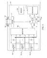
- FIG. 1 illustrates a block diagram of a battery management system 130, in accordance with one embodiment of the present invention.
- an undesired condition e.g., a micro-shorting connection
- a fault condition such as an over-voltage, over-current or over-temperature condition.
- the protection function of the battery management system 130 is improved relative to conventional designs.
- a battery pack includes multiple battery cells 102_1-102_N.
- a set of temperature sensors e.g., thermistors 104_1-104_N coupled to the battery cells 102_1-102_N, can sense temperatures of the battery cells 102_1-102_N respectively, and can generate monitoring signals corresponding to the temperatures of the battery cells 102_1-102_N to a multiplexer 110.
- a detector 108 coupled to the battery cells 102_1-102_N can detect cell voltages across the battery cells 102_1-102_N according to potential levels measured at two terminals of the battery cells 102_1-102_N, and can generate monitoring signals corresponding to the cell voltages of the battery cells 102_1-102_N to the multiplexer 110.
- the multiplexer 110 sequentially transfers the monitoring signals from the detector 108 and the thermistors 104_1-104_N to a converter, e.g., an analog to digital converter (ADC) 112, which converts the monitoring signals to digital signals.
- ADC analog to digital converter
- the digitized signals indicating the cell voltages and temperatures of the battery cells 102_1-102_N can be provided to a processor 118, for further processing.
- the processor 108 is a micro-processor.
- a current sensor e.g., a resistor 116 coupled to the battery cells 102_1-102_N in series, can provide a monitoring signal corresponding to a current flowing through the battery cells 102_1-102_N.
- the monitoring signal can be provided to a converter, e.g., an analog to digital converter (ADC) 114, which converts the monitoring signal to a digital signal.
- ADC analog to digital converter
- a digitized signal indicating the current of the battery cells 102_1-102_N can be also provided to the processor 118 for further processing.
- the ADCs 112 and 114 can periodically digitize the monitoring signals and provide the digitized signals to the processor 118.
- the ADCs 112 and 114 can digitize the received signals and provide the digitized signals to the processor 118 every 0.1 second.
- the processor 118 can store monitoring information for the battery cells 102_1-102_N in a memory 120 and detect whether an undesired condition, e.g., a micro-shorting connection, is present in the battery cells 102_1-102_N according to the monitoring information.
- a micro-shorting connection is a short circuit formed inside the battery cells.
- a micro-shorting connection can be caused by internal contamination of the battery cells, manufacturing-induced electrode damage, burrs on electrode tabs, weld spatter from cell lead attachment points, wrinkles or kinks in windings or tabs, electrode misalignment, poorly aging electrodes, postmanufacturing mechanical damage to cells, cell thermal abuse, etc.
- the battery management system 130 by detecting the undesired condition, e.g., the micro-shorting connection, the battery management system 130 triggers protective actions to prevent the undesired condition from developing into a fault condition such as an over-voltage, over-current or over-temperature condition, or can issue an alert signal to a user to indicate the fault condition.
- a fault condition such as an over-voltage, over-current or over-temperature condition
- a charging switch 142 and a discharging switch 144 are coupled to the battery cells 102_1-102_N in series.
- a driver 122 is coupled to the charging switch 142 and the discharging switch 144 to control the switches 142 and 144.
- the switch 142 is turned on and the switch 144 is turned off to enable a charging current into the battery cells.
- the switch 142 is turned off and the switch 144 is turned on to enable a discharging current out of the battery cells.
- the processor 118 can perform protective actions accordingly.
- the processor 118 informs the driver 122 to turn off the switches 142 and/or 144 to cut off a charging or discharging current flowing through the battery cell.
- the processor 118 can generate an alarm or alert signal to inform a user of the undesired condition.
- other protective actions can be performed on the battery cell to prevent the battery cell from being damaged or from generating a safety issue such as an explosion or fire.
- an undesired condition e.g., the micro-shorting connection
- multiple abnormal conditions may be present in the battery pack.
- the processor 118 can detect such abnormal conditions.
- the battery pack can stay in an idle state in which the battery pack is neither charged nor discharged.
- the cell voltages of the battery cells 102_1-102_N may drop slowly because of the power dissipation on its self-loads. If the battery cells 102_1-102_N are balanced, the cell voltages and capacities of the battery cells are approximately the same. As such, the voltage drop rates of the battery cells in the idle state are approximately the same. However, if a micro-shorting connection occurs in a battery cell, the cell voltage of that battery cell may drop faster than the cell voltages of other normal battery cells.
- the processor 118 can detect whether the first abnormal condition is present by comparing a voltage drop rate of the battery cell in a current time interval with a voltage drop rate of the battery cell in a previous time interval.
- the processor 118 further compares the average I AVE (n) during the time interval dT(n) with the average I AVE (n-1) during the previous time interval dT(n-1).
- the processor 118 determines that the battery pack is in the idle state. If the battery pack is in the idle state, the processor 118 further compares the voltage drop rate D(n) during the time interval dT(n) with a voltage drop rate D(n-1) during a time interval dT(n-1) stored in the memory 120. In one embodiment, the time intervals dT(n) and dT(n-1) have the same duration.
- the processor 118 can determine that a micro-shorting connection has occurred. The processor 118 can perform protective actions accordingly.
- D AVE1 represents an average of (N-1) voltage drop rates D(n-1), D(n-2), ... and D(1) of the battery cell during (N-1) time intervals dT(n-1), dT(n-2), ... and dT(1).
- the time intervals dT(1)-dT(n) are continuous time intervals and start from the time when the battery pack enters the idle state.
- the processor 118 can store the factor MC(1) in the memory 120 and can keep updating the factor MC(1) in subsequent time intervals.
- the processor 118 can detect whether the first abnormal condition is present by periodically comparing a voltage drop rate of a battery cell with voltage drop rates of other battery cells during a particular time interval.
- the processor 118 compares the voltage drop rates of the battery cells 102_1-102_N respectively during the time intervals dT(1)- dT(n). In a time interval dT(k) (1 ⁇ k ⁇ n), the processor 118 identifies the maximum D MAX from the voltage drop rates D(k)_1-D(k)_N of the battery cells 102_1-102_N and calculates an average D AVE2 of other voltage drop rates in the particular time interval excluding the maximum D MAX .
- the processor 118 determines that a micro-shorting connection has occurred in the battery cell having the maximum D MAX .
- the processor 118 can perform protective actions accordingly.
- the threshold D TH2 is the same as the threshold D TH1 .
- Detection of a second abnormal condition is described as follows.
- the cell voltage of the battery cell may increase slower than the cell voltages of other normal battery cells in the charging phase and decrease faster than the cell voltages of other normal battery cells in the discharging phase.
- the cell voltage of the battery cell is less than the cell voltages of other normal battery cells in a charging and discharging cycle.
- the processor 118 periodically compares cell voltages for the battery cells to detect whether the second abnormal condition is present during a charging and discharging cycle.
- the processor 118 compares cell voltages to identify a battery cell 102_M (1 ⁇ M ⁇ N) with the minimum V MINC of the cell voltages and calculates an average V AVED of the cell voltages of other battery cells excluding the battery cell 102_M.
- the processor 118 can calculate an average V AVED of the cell voltages of other battery cells excluding the battery cell 102_M.
- the processor 118 determines that a micro-shorting connection is present in the battery cell 102_M, in one embodiment.
- the processor 118 can perform protective actions accordingly.
- Detection of a third abnormal condition is described as follows.
- a fully charging capacity of the battery pack after the charging phase completes is greater than a fully discharging capacity of the battery pack after the discharging phase completes because of the power consumption on self-load of the battery pack.
- a self-discharging current may increase in the battery cell, thereby decreasing the fully discharging capacity.
- a difference between the fully charging capacity and the fully discharging capacity increases.
- the processor 118 compares the fully charging capacity and the fully discharging capacity of the battery pack in a charging and discharging cycle and detects whether the third abnormal condition is present in the battery pack according to the difference between the fully charging capacity and the fully discharging capacity.
- the processor 118 can integrate the current flowing into the battery pack during the charging phase to calculate a fully charging capacity Q C of the battery pack.
- the processor 118 can integrate the current flowing out of the battery pack during a discharging phase to calculate a fully discharging capacity Q D of the battery pack.
- the processor 118 can further calculate a difference Q L (n) between Q C and Q D and store the difference Q L (n) in the memory 120. Moreover, the processor 118 calculates an average Q L _ AVE of the differences Q L obtained in previous charging and discharging cycles that are stored in the memory 120. In one embodiment, the memory 120 stores a predetermined number of differences Q L (n) obtained in the latest charging and discharging cycles.
- the processor 118 determines that a micro-shorting connection is present in the battery pack.
- the processor 118 can perform protective actions accordingly.
- a micro-shorting connection may gradually form in a battery cell. Before the micro-shorting connection is completely formed, the cell voltage of the battery cell drops transiently while the charging/discharging current stays constant during a charging/discharging phase.
- the processor 118 compares a current I(n) of the battery pack at time T(n) with a current I(n-1) of the battery pack at time T(n-1). In one embodiment, the time interval between the time T(n) and the time T(n-1) is 0.1 second. If an absolute value of a difference between the currents I(n) and I(n-1) is less than a threshold, e.g., 0.1A, the processor 118 can further compare a cell voltage V(n) of a battery cell detected at time T(n) with a cell voltage V(n-1) of the battery cell detected at time T(n-1) to determine whether the fourth abnormal condition has occurred.
- a threshold e.g., 0.1A
- the processor 118 determines that a micro-shorting connection has occurred in the battery cell.
- the processor 118 can perform protective actions accordingly.
- Detection of a fifth abnormal condition is described as follows.
- the charging phase if the battery pack is charged in a constant voltage (CV) charging mode, the charging current of a battery cell gradually decreases and the cell voltage of the battery cell stays substantially constant. Under such circumstances, the internal power dissipation of the battery cell is relatively small.
- the battery pack stays in the idle state, e.g., no charging or discharging current flows into or out of the battery pack, the power dissipation is also relatively small.
- the processor 118 detects whether the fifth abnormal condition has occurred by periodically comparing a temperature of the battery cell at time T(n) with a temperature value of the battery cell at time T(n-1).
- the processor 118 can periodically receive monitoring signals corresponding to the temperature of a battery cell from the ADC 112. When the battery pack is charged in the CV charging mode or stays in the idle state, the processor 118 compares the temperature Temp(n) of the battery cell at time T(n) with the temperature Temp(n-1) of the battery cell at time T(n-1).
- the processor 118 determines that a micro-shorting connection has occurred in the battery cell.
- the processor 118 can perform protective actions accordingly.
- the processor 118 can detect whether the fifth abnormal condition has occurred, by periodically comparing a temperature variation of the battery cell during a time interval with the temperature variations of other battery cells during a particular time interval.
- the processor 118 can compare temperature variations dTemp _ 1-dTemp_N for the battery cells 102 _ 1-102_N, respectively, during the particular time interval. In the current time interval dT(n), the processor 118 identifies the maximum dTemp_M (1 ⁇ M ⁇ N) from the temperature variations dTemp_1-dTemp_N and calculates an average dTemp_ave of other temperature variations excluding the maximum dTemp_M.
- dTemp_M if a difference between dTemp_M and dTemp_ave is greater than a threshold dTemp_th, the processor 118 determines that a micro-shorting connection has occurred in the corresponding battery cell 102_M.
- the processor 118 can perform protective actions accordingly.
- the processor 118 can selectively add up all or some of the factors MC(1)-MC(7) and detect an undesired condition according to the summation of those factors. In one embodiment, if the summation MC is greater than a threshold MC TH , the processor 118 determines that an undesired condition has occurred in the battery pack. Thus, the processor 118 can performs protective actions.
- the processor 118 can detect an undesired condition according to the variations of the voltages, currents and temperatures of the battery cells before the undesired condition develops into a fault condition such as an over-voltage, over-current or over-temperature condition.
- the battery management system 130 can perform protective actions on the battery cell/pack to prevent the battery cell/pack from undergoing a fault condition.
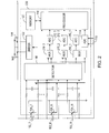
- FIG. 2 illustrates a block diagram of a battery management system 230, in accordance with another embodiment of the present invention. Elements that are labeled the same as in FIG. 1 have similar functions. FIG. 2 is described in combination with FIG. 1 .
- the battery management system 230 includes multiple multiplexers, e.g., multiplexers 210 _ 1, 210_2, and 210_3, coupled to the detector 108 and the thermistors 104_1-104_N, for transferring monitoring signals corresponding to the cell voltages and temperatures of the battery cells 102_1-102_N from the detector 108 and the thermistors 104_1-104_N to respective converters, e.g., analog to digital converters (ADCs) 212 _ 1, 212_2 and 212_3.
- ADCs analog to digital converters
- the battery cells 102_1-102_N can be divided into first, second and third cell groups.
- the detector 108 generates monitoring signals corresponding to the cell voltages of the battery cells in the first, second and third cell groups to the multiplexers 210_1, 210_2 and 210_3, respectively.
- the thermistors 104_1-104_N coupled to the battery cells in the first, second and third cell groups can generate monitoring signals corresponding to the temperatures of the battery cells in the first, second and third cell groups to the multiplexers 210_1, 210_2 and 210_3, respectively.
- the ADCs 212_1, 212_2 and 212_3 convert the monitoring signals of the battery cells in the first, second and third battery groups to respective digital signals, and can send the digitized signals to the processor 118 for further processing.
- monitoring signals corresponding to the cell voltages and temperatures of the battery cells can be divided into multiple groups.
- the monitoring signals in each group can be transferred to a corresponding ADC sequentially via a corresponding multiplexer and converted into digital signals by the corresponding ADC. Since multiple multiplexers and ADCs can work synchronously to transfer and digitize the monitoring signals of the corresponding battery cells, the processor 118 gets monitoring information for the battery cell 102_1-102_N faster, which improves system efficiency.
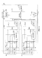
- FIG. 3 illustrates a block diagram of a battery management system 330 for managing multiple battery packs, in accordance with one embodiment of the present invention. Elements that are labeled the same as in FIG. 1 have similar functions. FIG. 3 is described in combination with FIG. 1 .
- the battery management system 330 can have a centrally-distributed and hierarchical architecture. However, the battery management system 330 can have other configurations and is not limited to a centrally-distributed and hierarchical architecture.
- multiple local battery management systems 330_1-330_N are coupled to battery packs 302_1-302_N, respectively, to manage the corresponding battery packs.
- the structures and functions of the local battery management system 330_1-330_N are similar to one another.
- a thermistor array 304_1 including multiple thermistors senses temperatures of battery cells in the battery pack 302_1 and generates monitoring signals indicating the temperatures of the battery cells in the battery pack 302_1.
- a detector 308_1 detects cell voltages of the battery cells in the battery pack 302_1 and generates monitoring signals corresponding to the cell voltages of the battery cells in the battery pack 302_1.
- Monitoring signals corresponding to the cell voltages and temperatures of the battery cells in the battery pack 302_1 are provided to a multiplexer 310_1.
- the multiplexer 310_1 can sequentially transfer the monitoring signals to a converter, e.g., an analog to digital converter (ADC) 312_1, which converts the monitoring signals to digital signals.
- ADC analog to digital converter
- the ADC 312_1 periodically sends the digitized signals which indicate the cell voltages and temperatures of the battery cells in the battery pack 302_1 to a central processor 318 for further processing.
- a digitized signal indicating a current flowing through the battery packs 302_1-302_N can be periodically provided to the central processor 318 via the resistor 116 and the ADC 114 in a manner similar to that described with respect to FIG. 1 .
- the central processor 318 functions similarly to the processor 118 in FIG. 1 such that the central processor 318 can detect the presence of an undesired condition, e.g., a micro-shorting connection, in one or more battery cells by detecting variations of the voltages and temperatures of the battery cells in the battery packs 302_1-302_N and/or by detecting variations of the current flowing through the battery packs 302_1-302_N.
- an undesired condition e.g., a micro-shorting connection
- the processor 118 can inform the driver 122 to turn off the switches 142 and/or 144 to cut off a charging or discharging current, generate an alarm or alert signal to inform a user of the undesired condition, and perform protective actions on the corresponding battery cell(s) to prevent the battery cell(s) from being damaged or from causing a safety issue such as an explosion or fire.
- Each of the battery packs 302_1-302_N can also be treated as a single battery cell, in one embodiment.
- a thermistor (not shown in FIG. 3 ) coupled to the battery pack 302_M can sense a temperature of the battery pack 302_M and generate a monitoring signal corresponding to the temperature of the battery pack 302_M.
- the internal detector 308_M can detect a voltage across the battery pack 302_M and generate a monitoring signal corresponding to the pack voltage of the battery pack 302_M.
- the monitoring signals corresponding to the pack voltage and temperature of the battery pack 302_M can be digitized by the internal ADC 312_M and then provided to the central processor 318 periodically.
- the central processor 318 8 can also detect the presence of an undesired condition, e.g., a micro-shorting connection, one or more battery packs by detecting variations among the pack voltages and temperatures of the battery packs 302_1-302_N and variations among the currents flowing through the battery packs 302_1-302_N.
- an undesired condition e.g., a micro-shorting connection
- FIG. 4 illustrates a block diagram of a battery management system 430 for managing multiple battery packs, in accordance with another embodiment of the present invention. Elements that are labeled the same as in FIG. 1 and FIG. 3 have similar functions. FIG. 4 is described in combination with FIG. 1 and FIG. 3 .
- each local battery management system 430_M (1 ⁇ M ⁇ N) includes a local processor 402_M and a memory 404_M.
- the internal ADC 312_M can periodically provide the digitized signals indicating cell voltages and temperatures of the battery cells in the battery pack 302_M into the local processor 402_M.
- the local processor 402_M functions in a manner similar to the processor 118 in FIG. 1 . More specifically, the local processor 402_M stores received monitoring information in the memory 120 and detects whether an abnormal condition has occurred in the battery pack 302_M according to the monitoring information. The local processor 402_M also calculates the factors MC(K) according to the monitoring information upon detecting an abnormal condition. If the local processor 402_M detects that an abnormal condition has occurred in the battery pack 302_M, the local processor 402_M informs the central processor 318 about the detected abnormal condition. Additionally, the local processor 402_M sends the calculated factors MC(K) corresponding to the battery pack 302_M to the central processor 318. The local processor 402_M can also transfer the digital signals indicating cell voltages and temperatures of the battery cells in the battery pack 302_M to the central processor 318.
- the local processor 402_1-402_N in the battery management system 430_1-430_N can help detect whether an abnormal condition has occurred in the battery packs 302_1-302_N and can calculate the factors MC(K) according to the variations of the cell voltages and temperatures of the battery cells in the battery packs 302_1-302_N, which helps lighten the workload of the central processor 318 and enhances the flexibility and efficiency of the overall system.
- the central processor 318 can detect whether an undesired condition has occurred in the battery packs 302_1-302_N according to the monitoring information and calculated factors MC(K) from the local processors 402_1-402_N.
- FIG. 5 illustrates a flowchart 500 of operations performed by a battery management system, e.g., the battery management system 130 in FIG. 1 , in accordance with one embodiment of the present invention.
- FIG. 5 is described in combination with FIG. 1 .
- the battery management system 130 monitors multiple parameters including voltages, currents and temperatures of multiple battery cells in block 504.
- the battery management system 130 determines whether an undesired condition, e.g., a micro-shorting connection, is present in the battery cells according to variations of selected parameters of the battery cells.
- the flowchart 500 goes to block 510. Otherwise, the flowchart 500 goes to block 512.
- the battery management system 130 performs protective actions to prevent the undesired condition from developing into a fault condition such as an over-voltage, over-current or over-temperature condition.
- the battery management system 130 calculates multiple factors MC(K) described above according to the variations of the parameters of the battery cells. In block 514, the battery management system 130 selectively adds up all or some of the factors MC(K) to calculate a summation MC of the factors. In block 514, if the summation MC is greater than a threshold MC TH , the battery management system 130 determines that an undesired condition is present in the battery cells and the flowchart 500 goes to block 510. Otherwise, the flowchart 500 returns to block 504 to continue monitoring the parameters of the battery cells.
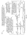
- FIG. 6 illustrates a flowchart 600 of a method for detecting the presence of an undesired condition in a battery pack, in accordance with one embodiment of the present invention.
- the battery pack includes multiple battery cells.
- FIG. 6 is described in combination with FIG. 1 .
- the battery management system 130 detects cell voltages of the battery cells while the battery pack stays in an idle state in which the battery pack is neither charged nor discharged. In one embodiment, the battery management system 130 can determine whether an undesired condition is present in a battery cell by comparing a voltage drop rate of the battery cell in a current time interval with a voltage drop rate of the battery cell in a previous time interval.
- the battery management system 130 calculates a voltage drop dV(n) of the battery cell during a current time interval dT(n). In block 606, the battery management 130 calculates a voltage drop rate D(n)-dV(n)/dT(n) of the battery cell during the time interval dT(n). In block 608, the battery management system 130 compares the voltage drop rate D(n) during the current time interval dT(n) with a voltage drop rate D(n-1) during a previous time interval dT(n-1).
- the battery management system 130 determines that an undesired condition has occurred in the battery cell in block 612. If the difference between D(n) and D(n-1) is not greater than the threshold D TH1 in block 610, the battery management system 130 calculates an average D AVE1 , of (n-1) voltage drop rates D(1)-D(n-1) during (n-1) previous time intervals dT(1)-dT(n-1) in block 614.
- the battery management system 13 0 can detect whether an undesired condition is present in a battery cell by comparing a voltage drop rate of the battery cell with voltage drop rates of other battery cells during the same time interval.
- the battery management system 130 calculates voltage drop rates D(n)s of the battery cells during a current time interval dT(n).
- the battery management system 130 identifies the maximum D MAX for the voltage drop rates D(n)s and calculates an average D AVE2 of other voltage drop rates excluding D MAX .
- the battery management system 130 determines that an undesired condition has occurred in the battery cell in block 612. Otherwise, the flowchart 600 goes to block 622.
- n is incremented by 1 in block 603
- the flowchart 600 returns to block 618 to calculate voltage drop rates D(n)s of the battery cells during a subsequent time interval dT(n).
- FIG. 7 illustrates a flowchart 700 of a method for detecting the presence of an undesired condition in a battery pack, in accordance with one embodiment of the present invention.
- the battery pack includes multiple battery cells.
- FIG. 7 is described in combination with FIG. 1 .
- the battery management system 130 detects cell voltages of the battery cells during a charging and discharging cycle.
- the battery management system 130 identifies a battery cell M with the minimum V MINC relative to other battery cells, and calculates an average V AVEC of the cell voltages of other battery cells excluding the cell M when the pack voltage of the battery pack increases to a first predetermined level during the charging phase.
- the battery management system 130 determines whether the battery cell M still has the minimum V MIND relative to the battery cells, and calculates an average V AVED of the cell voltages of other battery cells excluding the cell M when the pack voltage of the battery pack decreases to a second predetermined level.
- FIG. 8 illustrates a flowchart 800 of a method for detecting the presence of an undesired condition in a battery pack, in accordance with one embodiment of the present invention.
- FIG. 8 is described in combination with FIG. 1 .
- the battery management system 130 detects a charging current and a discharging current through a battery pack during a charging and discharging cycle.
- the battery management system 130 integrates the charging current flowing into the battery pack during the charging phase to calculate a fully charging capacity Q C of the battery pack, and integrates the discharging current flowing out of the battery pack during the discharging phase to calculate a fully discharging capacity Q D of the battery pack.
- the battery management system 130 calculates a difference Q L between Q C and Q D in the current charging and discharging cycle. In block 808, the battery management system 130 calculates an average Q L_AVE of the differences Q LS obtained in previous charging and discharging cycles. In block 810, if the difference Q L is greater than a threshold Q TH , the battery management system 130 determines that an undesired condition has occurred in the battery pack in block 812. Otherwise, the flowchart 800 goes to block 814.
- the flowchart 800 goes to block 816. Otherwise, the flowchart 800 returns to block 802.
- FIG. 9 illustrates a flowchart 900 of a method for detecting the presence of an undesired condition in a battery pack, in accordance with one embodiment of the present invention.
- the battery pack includes multiple battery cells.
- FIG. 9 is described in combination with FIG.1 .
- the battery management system 130 detects a voltage of a battery cell and a current flowing through the battery cell during a charging/discharging phase.
- the battery management system 130 compares a current I(n) of the battery cell detected at a current time T(n) with a current I(n-1) of the battery cell detected at a previous time T(n-1).
- a threshold I TH e.g., 0.1A
- the battery management system 130 compares a cell voltage V(n) of the battery cell detected at time T(n) with a cell voltage V(n-1) of the battery cell detected at time T(n-1). If a difference dV between V(n-1) and V(n) is greater than a threshold dV THR2 , the battery management system 130 determines that an undesired condition has occurred in the battery cell in block 912. Otherwise, the flowchart 900 goes to block 914. In block 914, if the difference dV is greater than a threshold dV THR1 , the flowchart 900 goes to block 916. Otherwise, the flowchart 900 returns to block 902.
- FIG. 10 illustrates a flowchart 1000 of a method for detecting the presence of an undesired condition in a battery pack, in accordance with one embodiment of the present invention.
- the battery pack includes multiple battery cells.
- FIG. 10 is described in combination with FIG. 1 .
- the battery management system 130 detects temperatures of the battery cells when the battery cells are charged in a constant voltage charging mode or stay in the idle state. In one embodiment, the battery management system 130 determines whether an undesired condition has occurred in a battery cell by comparing a temperature of the battery cell sensed at a current time with a temperature of the battery cell sensed at a previous time.
- the battery management system 130 compares a temperature Temp(n) of the battery cell sensed at a current time T(n) with a temperature Temp(n-1) of the battery cell sensed at a previous time T(n-1), and calculates a temperature variation (difference) dTemp between Temp(n) and Temp(n-1) during a time interval dT(n) between the time T(n) and T(n-1).
- the battery management system 130 determines that an undesired condition has occurred in the battery cell in block 1008. Otherwise, the flowchart 1000 goes to block 1010. In block 1010, if the temperature variation dTemp is greater than a threshold Temp_th1, the flowchart 1000 goes to block 1012. Otherwise, after n is incremented by 1 in block 1001, the flowchart 1000 returns to block 1004.
- the flowchart 1000 returns to block 1004 to compare a temperature Temp(n) of the battery cell sensed at time T(n) with the temperature Temp(n) of the battery cell sensed at time T(n-1).
- the battery management system 130 can detect whether an undesired condition has occurred in a battery cell by comparing a temperature variation of the battery cell with the temperature variations of other battery cells during a particular time interval.
- the battery management system 130 calculates temperature variations dTemps of the battery cells during a current time interval dT(n).
- the battery management system 130 identifies the maximum dTemp_M among the temperature variations dTemps and calculates an average dTemp_ave of other temperature variations excluding dTemp_M.
- n is incremented by 1 in block 1003
- the flowchart 1000 returns to block 1014 to calculate temperature variations dTemps of the battery cells during a time interval dT(n).
- the battery management system 130 can selectively add up all or some of the factors MC(1)-MC(7) calculated according to operations described in FIG. 6-10 and detect the presence of an undesired condition according to the summation of those factors.
- the battery management system can include a detector for detecting multiple parameters of the battery cells including voltages, currents and temperatures of the battery cells and generating monitoring signals corresponding to the parameters of the battery cells.
- the battery management system can also include one or more multiplexers for transferring the monitoring signals to one or more converters for converting the monitoring signals to digital signals.
- the battery management system can also include a processor for storing the digital signals indicating the parameters of the battery cells from the converter into a memory and determining whether an undesired condition, e.g., a micro-shorting connection, has occurred in the battery cells according to variations in the monitored parameters of the batteries.
- an undesired condition e.g., a micro-shorting connection
Landscapes
- Engineering & Computer Science (AREA)
- Power Engineering (AREA)
- General Physics & Mathematics (AREA)
- Physics & Mathematics (AREA)
- Mechanical Engineering (AREA)
- Transportation (AREA)
- Sustainable Energy (AREA)
- Health & Medical Sciences (AREA)
- General Health & Medical Sciences (AREA)
- Medical Informatics (AREA)
- Sustainable Development (AREA)
- Life Sciences & Earth Sciences (AREA)
- Secondary Cells (AREA)
- Charge And Discharge Circuits For Batteries Or The Like (AREA)
- Protection Of Static Devices (AREA)
Abstract
Description
- This application claims priority to
U.S. Provisional Application No. 61/359,657 - Battery packs or modules that include multiple battery cells can be used in various applications, such as laptop computers, electric vehicles/ hybrid electric vehicles (EVs/HEVs), and energy storage systems. During operation, a battery cell may undergo a fault condition, e.g., an over-voltage, over-current, over-temperature or cell internal micro-shorting condition, which may damage the battery cell or generate a safety issue such as an explosion or fire.
- A battery management system can be used to detect cell voltages, currents and temperatures of the battery cells and perform protective actions if a fault condition occurs. However, for filtering noise, there may be a predefined delay between the occurrence of a fault condition and the detection of a fault condition by the battery management system. As a result, the protective actions may not be performed timely in response to the fault condition, and thus the battery pack may be damaged or may generate a safety issue such as an explosion or fire.
- A battery management system for a battery pack that includes multiple battery cells is disclosed. The battery management system includes a detector coupled to the battery cells, multiple temperature sensors coupled to the battery cells, a current sensor coupled to the battery cells in series, and a processor coupled to the current sensor. The detector generates first monitoring signals corresponding to cell voltages across the battery cells. The temperature sensors generate second monitoring signals corresponding to temperatures of the battery cells. The current sensor generates third monitoring signals corresponding to currents of the battery cells. The processor determines whether an undesired condition is present according to the first, second, and third monitoring signals.
In a further aspect, a battery management system for a plurality of battery packs is provided, wherein each battery pack comprises a plurality of battery cells, said battery management system comprising: a plurality of local battery management systems, wherein each of said local battery management systems is coupled to a respective battery pack and comprises: a detector coupled to said battery cells and operable for generating first monitoring signals corresponding to cell voltages across said battery cells; and a plurality of temperature sensors coupled to said battery cells and operable for generating second monitoring signals corresponding to temperatures of said battery cells. Said battery management system further comprises a current sensor coupled to said battery packs in series and operable for generating third monitoring signals corresponding to currents of said battery packs; and a processor coupled to said current sensor and operable for determining whether an undesired condition is present according to said first, second, and third monitoring signals.
In a further aspect, a method is provided for managing a battery comprising a plurality of battery cells, said method comprising: detecting parameters of said battery cells, wherein said parameters comprise cell voltages, currents, and temperatures of said battery cells; generating monitoring signals according to said parameters; and determining whether an undesired condition is present in said battery cells according to said monitoring signals. - Features and advantages of embodiments of the subject matter will become apparent as the following detailed description proceeds, and upon reference to the drawings, wherein like numerals depict like parts, and in which:
-
FIG. 1 illustrates a block diagram of a battery management system, in accordance with one embodiment of the present invention. -
FIG. 2 illustrates a block diagram of a battery management system, in accordance with another embodiment of the present invention. -
FIG. 3 illustrates a block diagram of a battery management system for managing multiple battery packs, in accordance with one embodiment of the present invention. -
FIG. 4 illustrates a block diagram of a battery management system for managing multiple battery packs, in accordance with another embodiment of the present invention. -
FIG. 5 illustrates a flowchart of operations performed by a battery management system, in accordance with one embodiment of the present invention. -
FIG. 6 illustrates a flowchart of a method for detecting the presence of an undesired condition in a battery pack, in accordance with one embodiment of the present invention. -
FIG. 7 illustrates a flowchart of a method for detecting the presence of an undesired condition in a battery pack, in accordance with one embodiment of the present invention. -
FIG. 8 illustrates a flowchart of a method for detecting the presence of an undesired condition in a battery pack, in accordance with one embodiment of the present invention. -
FIG. 9 illustrates a flowchart of a method for detecting the presence of an undesired condition in a battery pack, in accordance with one embodiment of the present invention. -
FIG. 10 illustrates a flowchart of a method for detecting the presence of an undesired condition in a battery pack, in accordance with one embodiment of the present invention. - Reference will now be made in detail to the embodiments of the present invention. While the invention will be described in conjunction with these embodiments, it will be understood that they are not intended to limit the invention to these embodiments. On the contrary, the invention is intended to cover alternatives, modifications and equivalents, which may be included within the spirit and scope of the invention as defined by the appended claims.
- Furthermore, in the following detailed description of the present invention, numerous specific details are set forth in order to provide a thorough understanding of the present invention. However, it will be recognized by one of ordinary skill in the art that the present invention may be practiced without these specific details. In other instances, well known methods, procedures, components, and circuits have not been described in detail as not to unnecessarily obscure aspects of the present invention.
-
FIG. 1 illustrates a block diagram of abattery management system 130, in accordance with one embodiment of the present invention. According to embodiments of the invention, an undesired condition, e.g., a micro-shorting connection, can be detected in a battery cell according to multiple parameters of the battery cell before the undesired condition develops into a fault condition such as an over-voltage, over-current or over-temperature condition. Thus, the protection function of thebattery management system 130 is improved relative to conventional designs. - As shown in the example of
FIG. 1 , a battery pack includes multiple battery cells 102_1-102_N. In thebattery management system 130, a set of temperature sensors, e.g., thermistors 104_1-104_N coupled to the battery cells 102_1-102_N, can sense temperatures of the battery cells 102_1-102_N respectively, and can generate monitoring signals corresponding to the temperatures of the battery cells 102_1-102_N to amultiplexer 110. Furthermore, adetector 108 coupled to the battery cells 102_1-102_N can detect cell voltages across the battery cells 102_1-102_N according to potential levels measured at two terminals of the battery cells 102_1-102_N, and can generate monitoring signals corresponding to the cell voltages of the battery cells 102_1-102_N to themultiplexer 110. - In one embodiment, the
multiplexer 110 sequentially transfers the monitoring signals from thedetector 108 and the thermistors 104_1-104_N to a converter, e.g., an analog to digital converter (ADC) 112, which converts the monitoring signals to digital signals. The digitized signals indicating the cell voltages and temperatures of the battery cells 102_1-102_N can be provided to aprocessor 118, for further processing. In one embodiment, theprocessor 108 is a micro-processor. - Furthermore, a current sensor, e.g., a
resistor 116 coupled to the battery cells 102_1-102_N in series, can provide a monitoring signal corresponding to a current flowing through the battery cells 102_1-102_N. The monitoring signal can be provided to a converter, e.g., an analog to digital converter (ADC) 114, which converts the monitoring signal to a digital signal. Thus, a digitized signal indicating the current of the battery cells 102_1-102_N can be also provided to theprocessor 118 for further processing. - In operation, the
ADCs processor 118. By way of example, theADCs processor 118 every 0.1 second. - The
processor 118 can store monitoring information for the battery cells 102_1-102_N in amemory 120 and detect whether an undesired condition, e.g., a micro-shorting connection, is present in the battery cells 102_1-102_N according to the monitoring information. A micro-shorting connection is a short circuit formed inside the battery cells. A micro-shorting connection can be caused by internal contamination of the battery cells, manufacturing-induced electrode damage, burrs on electrode tabs, weld spatter from cell lead attachment points, wrinkles or kinks in windings or tabs, electrode misalignment, poorly aging electrodes, postmanufacturing mechanical damage to cells, cell thermal abuse, etc. Thus, by detecting the undesired condition, e.g., the micro-shorting connection, thebattery management system 130 triggers protective actions to prevent the undesired condition from developing into a fault condition such as an over-voltage, over-current or over-temperature condition, or can issue an alert signal to a user to indicate the fault condition. - In one embodiment, a
charging switch 142 and adischarging switch 144 are coupled to the battery cells 102_1-102_N in series. Adriver 122 is coupled to thecharging switch 142 and thedischarging switch 144 to control theswitches switch 142 is turned on and theswitch 144 is turned off to enable a charging current into the battery cells. During a discharging phase, theswitch 142 is turned off and theswitch 144 is turned on to enable a discharging current out of the battery cells. - In operation, if the
processor 118 detects the presence of an undesired condition, e.g., a micro-shorting connection, in a battery cell, theprocessor 118 can perform protective actions accordingly. In one embodiment, when theprocessor 118 detects that an undesired condition is present in a battery cell, theprocessor 118 informs thedriver 122 to turn off theswitches 142 and/or 144 to cut off a charging or discharging current flowing through the battery cell. Furthermore, theprocessor 118 can generate an alarm or alert signal to inform a user of the undesired condition. Additionally, other protective actions can be performed on the battery cell to prevent the battery cell from being damaged or from generating a safety issue such as an explosion or fire. - If an undesired condition, e.g., the micro-shorting connection, is present in a battery cell, multiple abnormal conditions may be present in the battery pack. The
processor 118 can detect such abnormal conditions. - Detection of a first abnormal condition is described as follows. The battery pack can stay in an idle state in which the battery pack is neither charged nor discharged. When the battery pack stays in the idle state, the cell voltages of the battery cells 102_1-102_N may drop slowly because of the power dissipation on its self-loads. If the battery cells 102_1-102_N are balanced, the cell voltages and capacities of the battery cells are approximately the same. As such, the voltage drop rates of the battery cells in the idle state are approximately the same. However, if a micro-shorting connection occurs in a battery cell, the cell voltage of that battery cell may drop faster than the cell voltages of other normal battery cells.
- In one embodiment, when the battery pack stays in the idle state, the
processor 118 can detect whether the first abnormal condition is present by comparing a voltage drop rate of the battery cell in a current time interval with a voltage drop rate of the battery cell in a previous time interval. - More specifically, the
processor 118 can calculate a voltage drop dV of a battery cell during a time interval dT(n) between the time T(n) and the time T(n-1) according to equation (1):
processor 118 calculates a voltage drop rate D(n) during the time interval dT(n) according to equation (2):
- Furthermore, the
processor 118 calculates an average IAVE(n) of the current flowing through the battery pack during the time interval dT(n) according to equation (3):
ADC 114 during the time interval dT(n). Theprocessor 118 further compares the average IAVE(n) during the time interval dT(n) with the average IAVE(n-1) during the previous time interval dT(n-1). - In one embodiment, if a difference between IAVE(n) and IAVE(n-1) is less than a threshold IE, the
processor 118 determines that the battery pack is in the idle state. If the battery pack is in the idle state, theprocessor 118 further compares the voltage drop rate D(n) during the time interval dT(n) with a voltage drop rate D(n-1) during a time interval dT(n-1) stored in thememory 120. In one embodiment, the time intervals dT(n) and dT(n-1) have the same duration. - If a difference between the voltage drop rate D(n) and the voltage drop rate D(n-1) is greater than a threshold DTH1, the
processor 118 can determine that a micro-shorting connection has occurred. Theprocessor 118 can perform protective actions accordingly. - If, however, the difference between the voltage drop rate D(n) and the voltage drop rate D(n-1) is not greater than the threshold DTH1, the
processor 118 can calculate a factor MC(1) according to equation (4):

processor 118 can store the factor MC(1) in thememory 120 and can keep updating the factor MC(1) in subsequent time intervals. - Alternatively, when the battery pack stays in the idle state, the
processor 118 can detect whether the first abnormal condition is present by periodically comparing a voltage drop rate of a battery cell with voltage drop rates of other battery cells during a particular time interval. - In one embodiment, the
processor 118 compares the voltage drop rates of the battery cells 102_1-102_N respectively during the time intervals dT(1)- dT(n). In a time interval dT(k) (1≤k≤n), theprocessor 118 identifies the maximum DMAX from the voltage drop rates D(k)_1-D(k)_N of the battery cells 102_1-102_N and calculates an average DAVE2 of other voltage drop rates in the particular time interval excluding the maximum DMAX. - In one embodiment, if a difference between DMAX and DAVE2 is greater than a threshold DTH2, the
processor 118 determines that a micro-shorting connection has occurred in the battery cell having the maximum DMAX. Theprocessor 118 can perform protective actions accordingly. In one embodiment, the threshold DTH2 is the same as the threshold DTH1. - If, however, the difference between DMAX and DAVE2 is not greater than the threshold DTH2, the
processor 118 can further calculate a factor MC(2) according to equation (6):
processor 118 can store the factor MC(2) in thememory 120 and can keep updating the factor MC(2) in subsequent time intervals. - Detection of a second abnormal condition is described as follows. During a charging and discharging cycle, if a micro-shorting connection is present in a battery cell, the cell voltage of the battery cell may increase slower than the cell voltages of other normal battery cells in the charging phase and decrease faster than the cell voltages of other normal battery cells in the discharging phase. Put differently, if a micro-shorting connection is present in a battery cell, the cell voltage of the battery cell is less than the cell voltages of other normal battery cells in a charging and discharging cycle.
- In one embodiment, the
processor 118 periodically compares cell voltages for the battery cells to detect whether the second abnormal condition is present during a charging and discharging cycle. During the charging phase of a charging and discharging cycle, when the pack voltage of the battery pack increases to a first predetermined level, theprocessor 118 compares cell voltages to identify a battery cell 102_M (1≤M≤N) with the minimum VMINC of the cell voltages and calculates an average VAVED of the cell voltages of other battery cells excluding the battery cell 102_M. During the discharging phase of the charging and discharging cycle, when the pack voltage of the battery pack decreases to a second predetermined level and if the battery cell 102_M still has the minimum VMIND among the battery cells 102_1-102_N, theprocessor 118 can calculate an average VAVED of the cell voltages of other battery cells excluding the battery cell 102_M. - If a difference VDC between VAVEC and VMINC and a difference VDD between VAVED and VMIND are both greater than a threshold VD2, the
processor 118 determines that a micro-shorting connection is present in the battery cell 102_M, in one embodiment. Theprocessor 118 can perform protective actions accordingly. - If, however, the differences VDC and VDD are both less than the threshold VD2, but are both greater than a threshold VD1, the
processor 118 can calculate a factor MC(3) according to equation (7):
processor 118 can store the factor MC(3) in thememory 120 and can keep updating the factor MC(3) in subsequent charging and discharging cycles. - Detection of a third abnormal condition is described as follows. In a charging and discharging cycle, a fully charging capacity of the battery pack after the charging phase completes is greater than a fully discharging capacity of the battery pack after the discharging phase completes because of the power consumption on self-load of the battery pack. However, if a micro-shorting connection occurs in a battery cell, a self-discharging current may increase in the battery cell, thereby decreasing the fully discharging capacity. As such, a difference between the fully charging capacity and the fully discharging capacity increases.
- In one embodiment, the
processor 118 compares the fully charging capacity and the fully discharging capacity of the battery pack in a charging and discharging cycle and detects whether the third abnormal condition is present in the battery pack according to the difference between the fully charging capacity and the fully discharging capacity. In a charging and discharging cycle C(n), theprocessor 118 can integrate the current flowing into the battery pack during the charging phase to calculate a fully charging capacity QC of the battery pack. Similarly, theprocessor 118 can integrate the current flowing out of the battery pack during a discharging phase to calculate a fully discharging capacity QD of the battery pack. - The
processor 118 can further calculate a difference QL(n) between QC and QD and store the difference QL(n) in thememory 120. Moreover, theprocessor 118 calculates an average QL_AVE of the differences QL obtained in previous charging and discharging cycles that are stored in thememory 120. In one embodiment, thememory 120 stores a predetermined number of differences QL(n) obtained in the latest charging and discharging cycles. - In one embodiment, if the difference QL(n) is greater than a threshold QTH, the
processor 118 determines that a micro-shorting connection is present in the battery pack. Theprocessor 118 can perform protective actions accordingly. - If, however, the difference QL(n) is not greater than the threshold QTH but greater than the average QL_AVE, the
processor 118 can calculate a factor MC(4) according to equation (8):
processor 118 can store the factor MC(4) in thememory 120 and can keep updating the factor MC(4) in a subsequent charging and discharging cycle. - Detection of a fourth abnormal condition is described as follows. A micro-shorting connection may gradually form in a battery cell. Before the micro-shorting connection is completely formed, the cell voltage of the battery cell drops transiently while the charging/discharging current stays constant during a charging/discharging phase.
- In one embodiment, during a charging or discharging phase, the
processor 118 compares a current I(n) of the battery pack at time T(n) with a current I(n-1) of the battery pack at time T(n-1). In one embodiment, the time interval between the time T(n) and the time T(n-1) is 0.1 second. If an absolute value of a difference between the currents I(n) and I(n-1) is less than a threshold, e.g., 0.1A, theprocessor 118 can further compare a cell voltage V(n) of a battery cell detected at time T(n) with a cell voltage V(n-1) of the battery cell detected at time T(n-1) to determine whether the fourth abnormal condition has occurred. - In one embodiment, if a difference dV between V(n-1) and V(n) is greater than a threshold dVTHR2, the
processor 118 determines that a micro-shorting connection has occurred in the battery cell. Theprocessor 118 can perform protective actions accordingly. - If, however, the difference dV is less than the threshold dVTHR2 but greater than a threshold dVTHR1, the
processor 118 can calculate a factor MC(5) according to equation (9):
processor 118 can store the factor MC(5) in thememory 120 and can keep updating the factor MC(5) in the current and next charging and discharging phases. - Detection of a fifth abnormal condition is described as follows. During the charging phase, if the battery pack is charged in a constant voltage (CV) charging mode, the charging current of a battery cell gradually decreases and the cell voltage of the battery cell stays substantially constant. Under such circumstances, the internal power dissipation of the battery cell is relatively small. Alternatively, if the battery pack stays in the idle state, e.g., no charging or discharging current flows into or out of the battery pack, the power dissipation is also relatively small.
- However, if a micro-shorting connection has occurred in the battery cell, an extra self-discharging current will exist in the battery cell. The extra self-discharging current is relatively high and can generate more heat. As a result, the temperature of the battery cell rises when the battery pack is charged in the CV charging mode or stays in the idle state.
- In one embodiment, when the battery pack is charged in the CV charging mode or stays in the idle state, the
processor 118 detects whether the fifth abnormal condition has occurred by periodically comparing a temperature of the battery cell at time T(n) with a temperature value of the battery cell at time T(n-1). - As described above, the
processor 118 can periodically receive monitoring signals corresponding to the temperature of a battery cell from theADC 112. When the battery pack is charged in the CV charging mode or stays in the idle state, theprocessor 118 compares the temperature Temp(n) of the battery cell at time T(n) with the temperature Temp(n-1) of the battery cell at time T(n-1). - In one embodiment, if a difference DTEMP between Temp(n) and Temp(n-1) is greater than a threshold Temp_th2, the
processor 118 determines that a micro-shorting connection has occurred in the battery cell. Theprocessor 118 can perform protective actions accordingly. - If, however, the difference DTEMP is less than the threshold Temp_th2 but greater than a threshold Temp_th1, the
processor 118 can calculate a factor MC(6) according to equation (10):
processor 118 can store the factor MC(6) in thememory 120 and can keep updating the factor MC(6). - Alternatively, when the battery pack is charged in the CV charging mode or stays in the idle state, the
processor 118 can detect whether the fifth abnormal condition has occurred, by periodically comparing a temperature variation of the battery cell during a time interval with the temperature variations of other battery cells during a particular time interval. - For example, when the battery pack is charged in the CV charging mode or stays in the idle state, the
processor 118 can compare temperature variations dTemp_1-dTemp_N for the battery cells 102_1-102_N, respectively, during the particular time interval. In the current time interval dT(n), theprocessor 118 identifies the maximum dTemp_M (1≤M≤N) from the temperature variations dTemp_1-dTemp_N and calculates an average dTemp_ave of other temperature variations excluding the maximum dTemp_M. - In one embodiment, if a difference between dTemp_M and dTemp_ave is greater than a threshold dTemp_th, the
processor 118 determines that a micro-shorting connection has occurred in the corresponding battery cell 102_M. Theprocessor 118 can perform protective actions accordingly. - If, however, the difference between dTemp_M and dTemp_ave is less than the threshold dTemp_th, the
processor 118 can calculate a factor MC(7) according to equation (11):
processor 118 can store the factor MC(7) in thememory 120 and can keep updating the factor MC(7). - In one embodiment, the
processor 118 can selectively add up all or some of the factors MC(1)-MC(7) and detect an undesired condition according to the summation of those factors. In one embodiment, if the summation MC is greater than a threshold MCTH, theprocessor 118 determines that an undesired condition has occurred in the battery pack. Thus, theprocessor 118 can performs protective actions. - Advantageously, the
processor 118 can detect an undesired condition according to the variations of the voltages, currents and temperatures of the battery cells before the undesired condition develops into a fault condition such as an over-voltage, over-current or over-temperature condition. As such, thebattery management system 130 can perform protective actions on the battery cell/pack to prevent the battery cell/pack from undergoing a fault condition. -
FIG. 2 illustrates a block diagram of abattery management system 230, in accordance with another embodiment of the present invention. Elements that are labeled the same as inFIG. 1 have similar functions.FIG. 2 is described in combination withFIG. 1 . - As shown in the example of
FIG. 2 , thebattery management system 230 includes multiple multiplexers, e.g., multiplexers 210_1, 210_2, and 210_3, coupled to thedetector 108 and the thermistors 104_1-104_N, for transferring monitoring signals corresponding to the cell voltages and temperatures of the battery cells 102_1-102_N from thedetector 108 and the thermistors 104_1-104_N to respective converters, e.g., analog to digital converters (ADCs) 212_1, 212_2 and 212_3. - In one embodiment, the battery cells 102_1-102_N can be divided into first, second and third cell groups. The
detector 108 generates monitoring signals corresponding to the cell voltages of the battery cells in the first, second and third cell groups to the multiplexers 210_1, 210_2 and 210_3, respectively. Similarly, the thermistors 104_1-104_N coupled to the battery cells in the first, second and third cell groups can generate monitoring signals corresponding to the temperatures of the battery cells in the first, second and third cell groups to the multiplexers 210_1, 210_2 and 210_3, respectively. Moreover, the ADCs 212_1, 212_2 and 212_3 convert the monitoring signals of the battery cells in the first, second and third battery groups to respective digital signals, and can send the digitized signals to theprocessor 118 for further processing. - Advantageously, monitoring signals corresponding to the cell voltages and temperatures of the battery cells can be divided into multiple groups. The monitoring signals in each group can be transferred to a corresponding ADC sequentially via a corresponding multiplexer and converted into digital signals by the corresponding ADC. Since multiple multiplexers and ADCs can work synchronously to transfer and digitize the monitoring signals of the corresponding battery cells, the
processor 118 gets monitoring information for the battery cell 102_1-102_N faster, which improves system efficiency. -
FIG. 3 illustrates a block diagram of abattery management system 330 for managing multiple battery packs, in accordance with one embodiment of the present invention. Elements that are labeled the same as inFIG. 1 have similar functions.FIG. 3 is described in combination withFIG. 1 . In one embodiment, thebattery management system 330 can have a centrally-distributed and hierarchical architecture. However, thebattery management system 330 can have other configurations and is not limited to a centrally-distributed and hierarchical architecture. - In the
battery management system 330, multiple local battery management systems 330_1-330_N are coupled to battery packs 302_1-302_N, respectively, to manage the corresponding battery packs. The structures and functions of the local battery management system 330_1-330_N are similar to one another. In the local battery management system 330_1, a thermistor array 304_1 including multiple thermistors senses temperatures of battery cells in the battery pack 302_1 and generates monitoring signals indicating the temperatures of the battery cells in the battery pack 302_1. Furthermore, a detector 308_1 detects cell voltages of the battery cells in the battery pack 302_1 and generates monitoring signals corresponding to the cell voltages of the battery cells in the battery pack 302_1. - Monitoring signals corresponding to the cell voltages and temperatures of the battery cells in the battery pack 302_1 are provided to a multiplexer 310_1. The multiplexer 310_1 can sequentially transfer the monitoring signals to a converter, e.g., an analog to digital converter (ADC) 312_1, which converts the monitoring signals to digital signals. Via a
bus 322, the ADC 312_1 periodically sends the digitized signals which indicate the cell voltages and temperatures of the battery cells in the battery pack 302_1 to acentral processor 318 for further processing. Additionally, a digitized signal indicating a current flowing through the battery packs 302_1-302_N can be periodically provided to thecentral processor 318 via theresistor 116 and theADC 114 in a manner similar to that described with respect toFIG. 1 . - In one embodiment, the
central processor 318 functions similarly to theprocessor 118 inFIG. 1 such that thecentral processor 318 can detect the presence of an undesired condition, e.g., a micro-shorting connection, in one or more battery cells by detecting variations of the voltages and temperatures of the battery cells in the battery packs 302_1-302_N and/or by detecting variations of the current flowing through the battery packs 302_1-302_N. If theprocessor 118 determines that an undesired condition has occurred in one or more battery cells, theprocessor 118 can inform thedriver 122 to turn off theswitches 142 and/or 144 to cut off a charging or discharging current, generate an alarm or alert signal to inform a user of the undesired condition, and perform protective actions on the corresponding battery cell(s) to prevent the battery cell(s) from being damaged or from causing a safety issue such as an explosion or fire. - Each of the battery packs 302_1-302_N can also be treated as a single battery cell, in one embodiment. Under such circumstance, in each local battery management system 330_M (1≤M≤N), a thermistor (not shown in
FIG. 3 ) coupled to the battery pack 302_M can sense a temperature of the battery pack 302_M and generate a monitoring signal corresponding to the temperature of the battery pack 302_M. Furthermore, the internal detector 308_M can detect a voltage across the battery pack 302_M and generate a monitoring signal corresponding to the pack voltage of the battery pack 302_M. The monitoring signals corresponding to the pack voltage and temperature of the battery pack 302_M can be digitized by the internal ADC 312_M and then provided to thecentral processor 318 periodically. As such, thecentral processor 318 8 can also detect the presence of an undesired condition, e.g., a micro-shorting connection, one or more battery packs by detecting variations among the pack voltages and temperatures of the battery packs 302_1-302_N and variations among the currents flowing through the battery packs 302_1-302_N. -
FIG. 4 illustrates a block diagram of abattery management system 430 for managing multiple battery packs, in accordance with another embodiment of the present invention. Elements that are labeled the same as inFIG. 1 andFIG. 3 have similar functions.FIG. 4 is described in combination withFIG. 1 andFIG. 3 . - In the battery management system 43 0, each local battery management system 430_M (1≤M≤N) includes a local processor 402_M and a memory 404_M. In each local battery management system 430_M, the internal ADC 312_M can periodically provide the digitized signals indicating cell voltages and temperatures of the battery cells in the battery pack 302_M into the local processor 402_M.
- In one embodiment, the local processor 402_M functions in a manner similar to the
processor 118 inFIG. 1 . More specifically, the local processor 402_M stores received monitoring information in thememory 120 and detects whether an abnormal condition has occurred in the battery pack 302_M according to the monitoring information. The local processor 402_M also calculates the factors MC(K) according to the monitoring information upon detecting an abnormal condition. If the local processor 402_M detects that an abnormal condition has occurred in the battery pack 302_M, the local processor 402_M informs thecentral processor 318 about the detected abnormal condition. Additionally, the local processor 402_M sends the calculated factors MC(K) corresponding to the battery pack 302_M to thecentral processor 318. The local processor 402_M can also transfer the digital signals indicating cell voltages and temperatures of the battery cells in the battery pack 302_M to thecentral processor 318. - Advantageously, the local processor 402_1-402_N in the battery management system 430_1-430_N can help detect whether an abnormal condition has occurred in the battery packs 302_1-302_N and can calculate the factors MC(K) according to the variations of the cell voltages and temperatures of the battery cells in the battery packs 302_1-302_N, which helps lighten the workload of the
central processor 318 and enhances the flexibility and efficiency of the overall system. Thecentral processor 318 can detect whether an undesired condition has occurred in the battery packs 302_1-302_N according to the monitoring information and calculated factors MC(K) from the local processors 402_1-402_N. -
FIG. 5 illustrates aflowchart 500 of operations performed by a battery management system, e.g., thebattery management system 130 inFIG. 1 , in accordance with one embodiment of the present invention.FIG. 5 is described in combination withFIG. 1 . - When the
battery management system 130 starts up inblock 502, thebattery management system 130 monitors multiple parameters including voltages, currents and temperatures of multiple battery cells inblock 504. Inblock 506, thebattery management system 130 determines whether an undesired condition, e.g., a micro-shorting connection, is present in the battery cells according to variations of selected parameters of the battery cells. Inblock 508, if thebattery management system 130 determines that an undesired condition has occurred in a battery cell, theflowchart 500 goes to block 510. Otherwise, theflowchart 500 goes to block 512. - In
block 510, thebattery management system 130 performs protective actions to prevent the undesired condition from developing into a fault condition such as an over-voltage, over-current or over-temperature condition. - In
block 512, thebattery management system 130 calculates multiple factors MC(K) described above according to the variations of the parameters of the battery cells. Inblock 514, thebattery management system 130 selectively adds up all or some of the factors MC(K) to calculate a summation MC of the factors. Inblock 514, if the summation MC is greater than a threshold MCTH, thebattery management system 130 determines that an undesired condition is present in the battery cells and theflowchart 500 goes to block 510. Otherwise, theflowchart 500 returns to block 504 to continue monitoring the parameters of the battery cells. -
FIG. 6 illustrates aflowchart 600 of a method for detecting the presence of an undesired condition in a battery pack, in accordance with one embodiment of the present invention. In one embodiment, the battery pack includes multiple battery cells.FIG. 6 is described in combination withFIG. 1 . - In
block 602, thebattery management system 130 detects cell voltages of the battery cells while the battery pack stays in an idle state in which the battery pack is neither charged nor discharged. In one embodiment, thebattery management system 130 can determine whether an undesired condition is present in a battery cell by comparing a voltage drop rate of the battery cell in a current time interval with a voltage drop rate of the battery cell in a previous time interval. - In
block 604, thebattery management system 130 calculates a voltage drop dV(n) of the battery cell during a current time interval dT(n). Inblock 606, thebattery management 130 calculates a voltage drop rate D(n)-dV(n)/dT(n) of the battery cell during the time interval dT(n). Inblock 608, thebattery management system 130 compares the voltage drop rate D(n) during the current time interval dT(n) with a voltage drop rate D(n-1) during a previous time interval dT(n-1). - In
block 610, if a difference between D(n) and D(n-1) is greater than a threshold DTH1, thebattery management system 130 determines that an undesired condition has occurred in the battery cell inblock 612. If the difference between D(n) and D(n-1) is not greater than the threshold DTH1 inblock 610, thebattery management system 130 calculates an average DAVE1, of (n-1) voltage drop rates D(1)-D(n-1) during (n-1) previous time intervals dT(1)-dT(n-1) inblock 614. Inblock 616, thebattery management system 130 calculates the factor MC(1) according to equation (4):
block 601, theflowchart 600 returns to block 604 to calculate a voltage drop dV(n) of the battery cell during a subsequent time interval dT(n). - In another embodiment, the battery management system 13 0 can detect whether an undesired condition is present in a battery cell by comparing a voltage drop rate of the battery cell with voltage drop rates of other battery cells during the same time interval.
- More specifically, in
block 618, thebattery management system 130 calculates voltage drop rates D(n)s of the battery cells during a current time interval dT(n). Inblock 620, thebattery management system 130 identifies the maximum DMAX for the voltage drop rates D(n)s and calculates an average DAVE2 of other voltage drop rates excluding DMAX. - In
block 622, if a difference between DMAX and DAVE2 is greater than a threshold DTH2, thebattery management system 130 determines that an undesired condition has occurred in the battery cell inblock 612. Otherwise, theflowchart 600 goes to block 622. Inblock 622, thebattery management system 130 calculates the factor MC(2) according to equation (6):
block 603, theflowchart 600 returns to block 618 to calculate voltage drop rates D(n)s of the battery cells during a subsequent time interval dT(n). -
FIG. 7 illustrates aflowchart 700 of a method for detecting the presence of an undesired condition in a battery pack, in accordance with one embodiment of the present invention. In one embodiment, the battery pack includes multiple battery cells.FIG. 7 is described in combination withFIG. 1 . - In
block 702, thebattery management system 130 detects cell voltages of the battery cells during a charging and discharging cycle. Inblock 704, thebattery management system 130 identifies a battery cell M with the minimum VMINC relative to other battery cells, and calculates an average VAVEC of the cell voltages of other battery cells excluding the cell M when the pack voltage of the battery pack increases to a first predetermined level during the charging phase. Inblock 706, thebattery management system 130 determines whether the battery cell M still has the minimum VMIND relative to the battery cells, and calculates an average VAVED of the cell voltages of other battery cells excluding the cell M when the pack voltage of the battery pack decreases to a second predetermined level. - In
block 708, if the battery cell M still has the minimum VMIND relative to other battery cells, theflowchart 700 goes to block 710. Otherwise, theflowchart 700 returns to block 702. - In
block 710, if a difference VDC between VAVEC and VMINC and a difference VDD between VAVED and VMIND are both greater than a threshold VD2, thebattery management system 130 determines that an undesired condition has occurred in the battery cell inblock 712. Otherwise, theflowchart 700 goes to block 714. Inblock 714, if the differences VDC and VDD are both greater than a threshold VD1, theflowchart 700 goes to block 716. Otherwise, theflowchart 700 returns to block 702. - In
block 716, thebattery management system 130 calculates the factor MC(3) according to equation (7):
flowchart 700 returns to block 702 to detect cell voltages of the battery cells during a subsequent charging and discharging cycle. -
FIG. 8 illustrates aflowchart 800 of a method for detecting the presence of an undesired condition in a battery pack, in accordance with one embodiment of the present invention.FIG. 8 is described in combination withFIG. 1 . - In
block 802, thebattery management system 130 detects a charging current and a discharging current through a battery pack during a charging and discharging cycle. Inblock 804, thebattery management system 130 integrates the charging current flowing into the battery pack during the charging phase to calculate a fully charging capacity QC of the battery pack, and integrates the discharging current flowing out of the battery pack during the discharging phase to calculate a fully discharging capacity QD of the battery pack. - In
block 806, thebattery management system 130 calculates a difference QL between QC and QD in the current charging and discharging cycle. Inblock 808, thebattery management system 130 calculates an average QL_AVE of the differences QLS obtained in previous charging and discharging cycles. Inblock 810, if the difference QL is greater than a threshold QTH, thebattery management system 130 determines that an undesired condition has occurred in the battery pack inblock 812. Otherwise, theflowchart 800 goes to block 814. - In
block 814, if the difference QL is greater than the average QL_AVE, theflowchart 800 goes to block 816. Otherwise, theflowchart 800 returns to block 802. Inblock 816, thebattery management system 130 calculates the factor MC(4) according to equation (8):
flowchart 800 returns to block 802 to detect a charging current and a discharging current flowing through the battery pack during a subsequent charging and discharging cycle. -
FIG. 9 illustrates aflowchart 900 of a method for detecting the presence of an undesired condition in a battery pack, in accordance with one embodiment of the present invention. In one embodiment, the battery pack includes multiple battery cells.FIG. 9 is described in combination withFIG.1 . - In
block 902, thebattery management system 130 detects a voltage of a battery cell and a current flowing through the battery cell during a charging/discharging phase. Inblock 904, thebattery management system 130 compares a current I(n) of the battery cell detected at a current time T(n) with a current I(n-1) of the battery cell detected at a previous time T(n-1). Inblock 906, if an absolute value of a difference between I(n) and I(n-1) is less than a threshold ITH, e.g., 0.1A, theflowchart 900 goes to block 908. Otherwise, theflowchart 900 returns to block 902. - In
block 908, thebattery management system 130 compares a cell voltage V(n) of the battery cell detected at time T(n) with a cell voltage V(n-1) of the battery cell detected at time T(n-1). If a difference dV between V(n-1) and V(n) is greater than a threshold dVTHR2, thebattery management system 130 determines that an undesired condition has occurred in the battery cell inblock 912. Otherwise, theflowchart 900 goes to block 914. Inblock 914, if the difference dV is greater than a threshold dVTHR1, theflowchart 900 goes to block 916. Otherwise, theflowchart 900 returns to block 902. - In
block 916, thebattery management system 130 calculates the factor MC(5) according to equation (9):
flowchart 900 returns to block 902 to detect the voltage of the battery cell and the current flowing through the battery cell during a subsequent charging/discharging phase. -
FIG. 10 illustrates aflowchart 1000 of a method for detecting the presence of an undesired condition in a battery pack, in accordance with one embodiment of the present invention. In one embodiment, the battery pack includes multiple battery cells.FIG. 10 is described in combination withFIG. 1 . - In
block 1002, thebattery management system 130 detects temperatures of the battery cells when the battery cells are charged in a constant voltage charging mode or stay in the idle state. In one embodiment, thebattery management system 130 determines whether an undesired condition has occurred in a battery cell by comparing a temperature of the battery cell sensed at a current time with a temperature of the battery cell sensed at a previous time. - In
block 1004, thebattery management system 130 compares a temperature Temp(n) of the battery cell sensed at a current time T(n) with a temperature Temp(n-1) of the battery cell sensed at a previous time T(n-1), and calculates a temperature variation (difference) dTemp between Temp(n) and Temp(n-1) during a time interval dT(n) between the time T(n) and T(n-1). - In
block 1006, if the temperature variation dTemp is greater than a threshold Temp_th2, thebattery management system 130 determines that an undesired condition has occurred in the battery cell inblock 1008. Otherwise, theflowchart 1000 goes to block 1010. Inblock 1010, if the temperature variation dTemp is greater than a threshold Temp_th1, theflowchart 1000 goes to block 1012. Otherwise, after n is incremented by 1 inblock 1001, theflowchart 1000 returns to block 1004. - In
block 1012, thebattery management system 130 calculates the factor MC(6) according to equation (10):
block 1001, theflowchart 1000 returns to block 1004 to compare a temperature Temp(n) of the battery cell sensed at time T(n) with the temperature Temp(n) of the battery cell sensed at time T(n-1). - In another embodiment, the
battery management system 130 can detect whether an undesired condition has occurred in a battery cell by comparing a temperature variation of the battery cell with the temperature variations of other battery cells during a particular time interval. - More specifically, in
block 1014, thebattery management system 130 calculates temperature variations dTemps of the battery cells during a current time interval dT(n). Inblock 1016, thebattery management system 130 identifies the maximum dTemp_M among the temperature variations dTemps and calculates an average dTemp_ave of other temperature variations excluding dTemp_M. - In
block 1018, if a difference between the maximum dTemp_M and the average dTemp_ave is greater than a threshold dTemp_th, thebattery management system 130 determines that an undesired condition has occurred in the battery cell that has the maximum dTemp_M inblock 1008, Otherwise, theflowchart 1000 goes to block 1020. - In
block 1020, thebattery management system 130 calculates the factor MC(7) according to equation (11):
block 1003, theflowchart 1000 returns to block 1014 to calculate temperature variations dTemps of the battery cells during a time interval dT(n). - Additionally, in one embodiment, the
battery management system 130 can selectively add up all or some of the factors MC(1)-MC(7) calculated according to operations described inFIG. 6-10 and detect the presence of an undesired condition according to the summation of those factors. - Accordingly, embodiments in accordance with the present invention provide a battery management system for protecting multiple battery cells from fault conditions. The battery management system can include a detector for detecting multiple parameters of the battery cells including voltages, currents and temperatures of the battery cells and generating monitoring signals corresponding to the parameters of the battery cells. The battery management system can also include one or more multiplexers for transferring the monitoring signals to one or more converters for converting the monitoring signals to digital signals. The battery management system can also include a processor for storing the digital signals indicating the parameters of the battery cells from the converter into a memory and determining whether an undesired condition, e.g., a micro-shorting connection, has occurred in the battery cells according to variations in the monitored parameters of the batteries. By detecting the presence of an undesired condition, the battery management system can trigger protective actions to prevent the undesired condition from developing into a fault condition such as an over-voltage, over-current or over-temperature condition.
- While the foregoing description and drawings represent embodiments of the present invention, it will be understood that various additions, modifications and substitutions may be made therein without departing from the spirit and scope of the principles of the present invention as defined in the accompanying claims. One skilled in the art will appreciate that the invention may be used with many modifications of form, structure, arrangement, proportions, materials, elements, and components and otherwise, used in the practice of the invention, which are particularly adapted to specific environments and operative requirements without departing from the principles of the present invention. The presently disclosed embodiments are therefore to be considered in all respects as illustrative and not restrictive, the scope of the invention being indicated by the appended claims and their legal equivalents, and not limited to the foregoing description.
Claims (16)
- A battery management system for a battery pack comprising a plurality of battery cells, said battery management system comprising:a detector coupled to said battery cells and operable for generating first monitoring signals corresponding to cell voltages across said battery cells;a plurality of temperature sensors coupled to said battery cells and operable for generating second monitoring signals corresponding to temperatures of said battery cells;a current sensor coupled to said battery cells in series and operable for generating third monitoring signals corresponding to currents of said battery cells; anda processor coupled to said current sensor and operable for determining whether an undesired condition is present according to said first, second, and third monitoring signals.
- The battery management system of claim 1, wherein said processor compares a charging capacity of said battery pack with a discharging capacity of said battery pack, wherein said undesired condition is present if a difference between said charging capacity and said discharging capacity is greater than a threshold.
- The battery management system of claim 1, wherein said processor compares a current of said battery pack at a first time with a current of said battery pack at a second time and compares a cell voltage at said first time with a cell voltage at said second time, wherein said undesired condition is present if an absolute value of a difference between said current of said battery pack at said first time and said current of said battery pack at said second time is less than a first threshold and a difference between said cell voltage at said first time and said cell voltage at said second time is greater than a second threshold.
- A battery management system according to one of claim 1 to 3 adapted for managing of a plurality of battery packs, wherein each battery pack comprises a plurality of battery cells, said battery management system comprising:a plurality of local battery management systems, wherein each of said local battery management systems is coupled to a respective battery pack and comprises:a detector coupled to said battery cells and operable for generating first monitoring signals corresponding to cell voltages across said battery cells; anda plurality of temperature sensors coupled to said battery cells and operable for generating second monitoring signals corresponding to temperatures of said battery cells;wherein said current sensor is coupled to said battery packs in series and operable for generating third monitoring signals corresponding to currents of said battery packs andwherein said processor is coupled to said current sensor and operable for determining whether an undesired condition is present according to said first, second, and third monitoring signals.
- The battery management system of one of claims 1 to 4,
wherein in an idle state, said processor compares voltage drop rates of said battery cells in a first time interval with voltage drop rates of said battery cells in a second time interval, wherein said undesired condition is present if a difference between said voltage drop rates of said battery cells in said first time interval and said voltage drop rates of said battery cells in said second time interval is greater than a first threshold; and
wherein in said idle state, said processor compares voltage drop rates for said battery cells in a particular time interval to identify the maximum of said voltage drop rates in said particular time interval and compares said maximum with an average of other voltage drop rates in said particular time interval excluding said maximum, wherein said undesired condition is present if a difference between said maximum and said average is greater than a second threshold. - The battery management system of one of claims 1 to 5, wherein said processor compares cell voltages for said battery cells in a charging phase to identify the first minimum of said cell voltages in said charging phase and compares said first minimum with a first average of other cell voltages during said charging phase excluding said first minimum, compares cell voltages for said battery cells in a discharging phase to identify the second minimum of said cell voltages in said discharging phase and compares said second minimum with a second average of other cell voltages during said discharging phase excluding said second minimum, wherein said undesired condition is present if a difference between said first average and said first minimum and a difference between said second average and said second minimum are greater than a first threshold.
- The battery management system of one of claims 4 to 6, wherein said processor compares a charging capacity of said battery packs with a discharging capacity of said battery packs, wherein said undesired condition is present if a difference between said charging capacity and said discharging capacity is greater than a threshold.
- The battery management system of one of claims 4 to 7,
wherein said processor compares a current of said battery packs at a first time with a current of said battery packs at a second time and compares a cell voltage at said first time with a cell voltage at said second time, wherein said undesired condition is present if an absolute value of a difference between said current of said battery packs at said first time and said current of said battery packs at said second time is less than a first threshold and a difference between said cell voltage at said first time and said cell voltage at said second time is greater than a second threshold. - The battery management system of one of claims 1 to 8,
wherein said processor compares said temperatures of said battery cells at a first time with said temperatures of said battery cells at a second time, wherein said undesired condition is present if a difference between said temperatures of said battery cells at said first time and said temperatures of said battery cells at said second time is greater than a first threshold; and
wherein said processor compares temperature variations for said battery cells in a particular time interval to identify the maximum of said temperature variations in said particular time interval and compares said maximum with an average of other temperature variations during said particular time interval excluding said maximum, wherein said undesired condition is present if a difference between said maximum and said average is greater than a second threshold. - The battery management system of one of claims 1 to 9, wherein said processor calculates a plurality of factors according to combinations of said cell voltages, said temperatures, and said currents, wherein said undesired condition is present if a summation of said factors is greater than a threshold.
- A method for managing a battery comprising a plurality of battery cells, said method comprising:detecting parameters of said battery cells, wherein said parameters comprise cell voltages, currents, and temperatures of said battery cells;generating monitoring signals according to said parameters; anddetermining whether an undesired condition is present in said battery cells according to said monitoring signals.
- The method of claim 11, further comprising, in an idle state:comparing voltage drop rates of said battery cells in a first time interval with voltage drop rates of said battery cells in a second time interval;determining that said undesired condition is present if a difference between said voltage drop rates of said battery cells in said first time interval and said voltage drop rates of said battery cells in said second time interval is greater than a first threshold;comparing voltage drop rates for said battery cells in a particular time interval to identify the maximum of said voltage drop rates in said particular time interval;comparing said maximum with an average of other voltage drop rates in said particular time interval excluding said maximum; anddetermining that said undesired condition is present if a difference between said maximum and said average is greater than a second threshold.
- The method of claim 11, further comprising:comparing cell voltages for said battery cells in a charging phase to identify the first minimum of said cell voltages in said charging phase;comparing said first minimum with a first average of other cell voltages during said charging phase excluding said first minimum;comparing cell voltages for said battery cells in a discharging phase to identify the second minimum of said cell voltages in said discharging phase;comparing said second minimum with a second average of other cell voltages during said discharging phase excluding said second minimum; anddetermining that said undesired condition is present if a difference between said first average and said first minimum and a difference between said second average and said second minimum are greater than a first threshold.
- The method of claim 11, further comprising:comparing a charging capacity of said battery pack with a discharging capacity of said battery pack; anddetermining that said undesired condition is present if a difference between said charging capacity and said discharging capacity is greater than a threshold.
- The method of claim 11, further comprising:comparing a current of said battery pack at a first time with a current of said battery pack at a second time;comparing a cell voltage at said first time with a cell voltage at said second time; anddetermining that said undesired condition is present if an absolute value of a difference between said current of said battery pack at said first time and said current of said battery pack at said second time is less than a first threshold and a difference between said cell voltage at said first time and said cell voltage at said second time is greater than a second threshold.
- The method of claim 11, further comprising:comparing said temperatures of said battery cells at a first time with said temperatures of said battery cells at a second time;determining that said undesired condition is present if a difference between said temperatures of said battery cells at said first time and said temperatures of said battery cells at said second time is greater than a first threshold;comparing temperature variations for said battery cells in a particular time interval to identify the maximum of said temperature variations in said particular time interval;comparing said maximum with an average of other temperature variations during said particular time interval excluding said maximum; anddetermining that said undesired condition is present if a difference between said maximum and said average is greater than a second threshold.
Applications Claiming Priority (2)
| Application Number | Priority Date | Filing Date | Title |
|---|---|---|---|
| US35965710P | 2010-06-29 | 2010-06-29 | |
| US12/982,003 US8219333B2 (en) | 2010-06-29 | 2010-12-30 | Battery management systems for protecting batteries from fault conditions |
Publications (2)
| Publication Number | Publication Date |
|---|---|
| EP2403105A2 true EP2403105A2 (en) | 2012-01-04 |
| EP2403105A3 EP2403105A3 (en) | 2014-07-09 |
Family
ID=44118220
Family Applications (1)
| Application Number | Title | Priority Date | Filing Date |
|---|---|---|---|
| EP11168682.0A Withdrawn EP2403105A3 (en) | 2010-06-29 | 2011-06-03 | Battery management systems for protecting batteries from fault conditions |
Country Status (5)
| Country | Link |
|---|---|
| US (1) | US8219333B2 (en) |
| EP (1) | EP2403105A3 (en) |
| JP (1) | JP5787581B2 (en) |
| CN (1) | CN102315663B (en) |
| TW (1) | TW201203779A (en) |
Cited By (17)
| Publication number | Priority date | Publication date | Assignee | Title |
|---|---|---|---|---|
| CN102673418A (en) * | 2012-05-11 | 2012-09-19 | 许继集团有限公司 | Connection failure judging and protecting method of power cell boxes as well as protecting system and device |
| DE102013204539A1 (en) * | 2013-03-15 | 2014-09-18 | Robert Bosch Gmbh | Battery cell device with fine-circuit safety function and method for monitoring a battery cell |
| DE102013204534A1 (en) * | 2013-03-15 | 2014-09-18 | Robert Bosch Gmbh | Battery cell device with short circuit safety function and method for monitoring a battery cell |
| DE102013204536A1 (en) * | 2013-03-15 | 2014-09-18 | Robert Bosch Gmbh | Battery cell device with transport safety function and method for monitoring a battery cell |
| DE102013211692A1 (en) * | 2013-06-20 | 2014-12-24 | Bayerische Motoren Werke Aktiengesellschaft | Circuit arrangement and energy storage system |
| DE102013220684A1 (en) * | 2013-10-14 | 2015-04-16 | Robert Bosch Gmbh | A battery management system for monitoring and controlling the operation of a rechargeable battery and battery system having such a battery management system |
| WO2015139927A1 (en) * | 2014-03-18 | 2015-09-24 | Robert Bosch Gmbh | Method for detecting anomalies in a battery cell, and short-circuit sensor system |
| EP3243252A4 (en) * | 2015-01-08 | 2018-09-12 | Nextek Power Systems, Inc. | Arrangement for and method of dynamically managing electrical power between an electrical power source and an electrical load |
| WO2018219701A1 (en) * | 2017-05-31 | 2018-12-06 | Bayerische Motoren Werke Aktiengesellschaft | Vehicle energy store |
| WO2019037110A1 (en) * | 2017-08-25 | 2019-02-28 | 深圳市云中飞网络科技有限公司 | Terminal equipment, battery system and battery abnormality detecting device |
| EP3611817A1 (en) * | 2018-08-13 | 2020-02-19 | Samsung SDI Co., Ltd. | Appratus and method of controlling battery |
| KR20200019083A (en) * | 2018-08-13 | 2020-02-21 | 삼성에스디아이 주식회사 | Battery control appratus and method for detection internal short of battery |
| DE102020203586A1 (en) | 2020-03-20 | 2021-09-23 | Robert Bosch Gesellschaft mit beschränkter Haftung | Protection device for an electronic component connected to an interface |
| US20220144097A1 (en) * | 2020-11-06 | 2022-05-12 | Hyundai Motor Company | System and method for managing vehicle battery |
| EP4057018A4 (en) * | 2019-11-25 | 2022-12-28 | Guangdong Oppo Mobile Telecommunications Corp., Ltd. | Method and device for determining short circuit in battery, and electronic device |
| WO2023025753A3 (en) * | 2021-08-23 | 2023-11-23 | Webasto SE | Battery and battery control method |
| FR3138949A1 (en) * | 2022-08-19 | 2024-02-23 | Psa Automobiles Sa | MONITORING CELL OVERVOLTAGES OF A CELLULAR BATTERY OF A SYSTEM DURING RECHARGE |
Families Citing this family (78)
| Publication number | Priority date | Publication date | Assignee | Title |
|---|---|---|---|---|
| JP5554622B2 (en) * | 2010-04-21 | 2014-07-23 | 株式会社マキタ | Electric tool equipment |
| DE102010041492A1 (en) * | 2010-09-28 | 2012-03-29 | Robert Bosch Gmbh | Method and arrangement for monitoring at least one battery, battery with such an arrangement and a motor vehicle with a corresponding battery |
| US9595847B2 (en) | 2010-11-04 | 2017-03-14 | Elite Power Solutions Llc | Uninterrupted lithium battery power supply system |
| US9000935B2 (en) * | 2011-03-31 | 2015-04-07 | Elite Power Solutions Llc | Battery management system |
| US9851412B2 (en) * | 2010-11-09 | 2017-12-26 | International Business Machines Corporation | Analyzing and controlling performance in a composite battery module |
| JP2012198175A (en) * | 2011-03-23 | 2012-10-18 | Suzuki Motor Corp | Battery state monitor device |
| US10358043B2 (en) | 2011-03-31 | 2019-07-23 | Elite Power Solutions, LLC | Golf cart battery system |
| US10116149B1 (en) | 2011-03-31 | 2018-10-30 | Elite Power Solutions, LLC | Automatic control system for a rechargeable battery system |
| US9553460B2 (en) | 2011-03-31 | 2017-01-24 | Elite Power Solutions Llc | Wireless battery management system |
| US10084334B1 (en) | 2011-03-31 | 2018-09-25 | Elite Power Solutions, LLC | Home energy storage battery system |
| US20130214601A1 (en) * | 2012-02-20 | 2013-08-22 | System General Corp. | Interface circuits for cascade and series battery management and methods thereof |
| CN104137379B (en) * | 2012-02-29 | 2016-09-07 | Nec能源元器件株式会社 | Battery control system, battery pack, electronic equipment and charger |
| TWI450471B (en) * | 2012-03-02 | 2014-08-21 | Ship & Ocean Ind R & D Ct | A multi-party communication system and charge process of a dc charging system |
| CN103579708B (en) * | 2012-07-24 | 2016-04-27 | 联想(北京)有限公司 | A kind of battery temperature monitoring method and device, battery |
| WO2014045745A1 (en) * | 2012-09-18 | 2014-03-27 | Necエナジーデバイス株式会社 | Power storage system and battery protection method |
| US10106038B2 (en) | 2012-12-28 | 2018-10-23 | Johnson Controls Technology Company | Dual function battery system and method |
| EP2770336A2 (en) * | 2013-02-21 | 2014-08-27 | Samsung SDI Co., Ltd. | Apparatus for detecting faults in battery system |
| US20140373894A1 (en) * | 2013-06-25 | 2014-12-25 | Volterra Semiconductor Corporation | Photovoltaic Panels Having Electrical Arc Detection Capability, And Associated Systems And Methods |
| DE102014102352A1 (en) | 2014-02-24 | 2015-08-27 | Ge Energy Power Conversion Technology Limited | Battery storage system with arc fault protection, energy conversion system and protection method |
| JP6217564B2 (en) * | 2014-09-01 | 2017-10-25 | ダイムラー・アクチェンゲゼルシャフトDaimler AG | Battery failure judgment device |
| US9680471B2 (en) | 2014-12-23 | 2017-06-13 | Apple Inc. | Apparatus for a reduced current wake-up circuit for a battery management system |
| KR102256300B1 (en) * | 2015-01-08 | 2021-05-26 | 삼성에스디아이 주식회사 | Battery pack |
| CN104617330B (en) * | 2015-01-19 | 2017-01-25 | 清华大学 | Recognition method of micro-short circuiting of batteries |
| EP3109653B1 (en) * | 2015-06-23 | 2022-04-27 | Robert Bosch GmbH | Method for detection of a short circuit within an energy storage device |
| US20210278470A1 (en) * | 2015-08-19 | 2021-09-09 | FCA Fiat Chrysler Automovies Brasil Ltda. | System and Method of Battery Monitoring |
| CN105203962B (en) * | 2015-08-31 | 2018-01-19 | 北汽福田汽车股份有限公司 | A kind of on-vehicle battery excessively stream diagnostic method and device |
| KR102559199B1 (en) * | 2015-11-02 | 2023-07-25 | 삼성전자주식회사 | Method of managing battery and batter management appratus |
| JP6394572B2 (en) * | 2015-11-18 | 2018-09-26 | 京セラドキュメントソリューションズ株式会社 | User interface device, image processing device, and notification method |
| JPWO2017110578A1 (en) * | 2015-12-25 | 2018-09-06 | ローム株式会社 | Current monitoring circuit, coulomb counter circuit, battery management system using them, and automobile |
| CN105472165B (en) * | 2015-12-31 | 2019-08-16 | 宇龙计算机通信科技(深圳)有限公司 | The control method and control device of mobile terminal |
| US10686321B2 (en) * | 2016-01-29 | 2020-06-16 | Robert Bosch Gmbh | Secondary battery management |
| TWI581542B (en) | 2016-03-01 | 2017-05-01 | 財團法人工業技術研究院 | Battery management system and battery system using the same |
| JP6743430B2 (en) * | 2016-03-11 | 2020-08-19 | マックス株式会社 | Battery pack |
| US9929571B1 (en) | 2016-03-29 | 2018-03-27 | Elite Power Solutions Llc | Integrated energy storage system |
| CN105958590B (en) * | 2016-06-08 | 2018-08-28 | 西安特锐德智能充电科技有限公司 | The device and method of battery charging process exception is judged according to charge capacity variation |
| KR102167424B1 (en) * | 2016-06-17 | 2020-10-19 | 주식회사 엘지화학 | Determining circuit and driving method for dual protection to high temperature |
| TWI614512B (en) * | 2016-07-14 | 2018-02-11 | 神基科技股份有限公司 | Gauging method for battery discharge-capacity corresponding to temperature and electronic device using the same |
| US10333182B2 (en) * | 2016-07-26 | 2019-06-25 | GM Global Technology Operations LLC | Estimation of cell voltage excursion in the presence of battery pack sensing faults |
| CN106450581B (en) * | 2016-08-30 | 2023-11-10 | 深圳市天翔宇科技有限公司 | Heating system for cylindrical battery module and battery module |
| JP6599831B2 (en) * | 2016-09-16 | 2019-10-30 | トヨタ自動車株式会社 | Battery temperature monitoring system |
| JP6599834B2 (en) * | 2016-09-21 | 2019-10-30 | トヨタ自動車株式会社 | Battery temperature monitoring system |
| US20190229548A1 (en) * | 2016-12-12 | 2019-07-25 | Shenzhen Royole Technologies Co. Ltd. | Electronic device and charging control method thereof |
| KR20180090145A (en) * | 2017-02-02 | 2018-08-10 | 삼성에스디아이 주식회사 | Battery management system and batterm management method |
| CN107144722A (en) * | 2017-04-16 | 2017-09-08 | 知豆电动汽车有限公司 | Battery pressure drop rate alarm method |
| CN108732448A (en) | 2017-04-24 | 2018-11-02 | 凹凸电子(武汉)有限公司 | Wire break detection method and broken string in battery management system release detection method |
| GB2551081B (en) | 2017-08-18 | 2018-12-19 | O2Micro Inc | Fault detection for battery management systems |
| CN107742754B (en) * | 2017-09-26 | 2020-11-17 | 深圳市国创动力系统有限公司 | State evaluation method of lithium titanate power battery system |
| TWI658673B (en) * | 2017-10-18 | 2019-05-01 | 宏碁股份有限公司 | Battery management unit |
| US10847835B2 (en) | 2017-12-13 | 2020-11-24 | William Jeffrey Schlanger | Battery management system for battery banks with a small number of cells |
| FI127776B (en) * | 2018-02-08 | 2019-02-15 | Akkurate Oy | System for determining an indicator of an internal leakage current of a battery entity |
| DK3524987T3 (en) * | 2018-02-08 | 2020-06-02 | Akkurate Oy | SYSTEM FOR DETERMINING AN INDICATOR OF AN INTERNAL LEAK CURRENT IN A BATTERY UNIT |
| JP6888733B2 (en) * | 2018-03-01 | 2021-06-16 | 株式会社村田製作所 | Batteries |
| CN110308393A (en) * | 2018-03-21 | 2019-10-08 | 宝沃汽车(中国)有限公司 | Fault detection method, device, battery pack and vehicle |
| GB2563489B (en) | 2018-04-19 | 2019-12-04 | O2Micro Inc | Battery protection systems |
| TWI665873B (en) * | 2018-08-10 | 2019-07-11 | 廣錠科技股份有限公司 | Control device capable of controlling target device according to feedback signal and method thereof |
| CN109038756B (en) * | 2018-08-31 | 2022-04-26 | 浙江天泰机械有限公司 | Battery pack control method, device and system and battery pack |
| US11105858B2 (en) | 2018-10-03 | 2021-08-31 | O2Micro Inc. | Predicting a potential fault in a battery |
| KR20200101754A (en) * | 2019-02-20 | 2020-08-28 | 삼성에스디아이 주식회사 | Battery control appratus and battery control method |
| US11327121B2 (en) * | 2019-04-03 | 2022-05-10 | Transportation Ip Holdings, Llc | Deviation detection system for energy storage system |
| US20220266695A1 (en) * | 2019-04-03 | 2022-08-25 | Transportation Ip Holdings, Llc | Deviation detection system for power circuit |
| KR102718122B1 (en) * | 2019-05-02 | 2024-10-15 | 주식회사 엘지에너지솔루션 | Apparatus, method and battery pack for detecting fault of electric conductor |
| KR20200137509A (en) * | 2019-05-30 | 2020-12-09 | 주식회사 엘지화학 | Apparatus and method for detecting crack of battery pack |
| CN114883672A (en) * | 2019-06-27 | 2022-08-09 | 奥动新能源汽车科技有限公司 | Safety processing device of battery pack, electric energy storage device and control method of electric energy storage device |
| CN110534822B (en) * | 2019-07-19 | 2023-06-02 | 贵州热缆技术有限责任公司 | Power battery fault early warning system |
| EP3790139A1 (en) * | 2019-09-03 | 2021-03-10 | ABB Schweiz AG | Battery management and protection system |
| CN112666477B (en) * | 2019-10-15 | 2022-06-03 | 东莞新能德科技有限公司 | Method for determining short circuit in battery, electronic device, and storage medium |
| JP7323800B2 (en) | 2019-10-18 | 2023-08-09 | ミツミ電機株式会社 | Secondary battery protection circuit, secondary battery protection device, battery pack and temperature detection circuit |
| DE102019216225A1 (en) * | 2019-10-22 | 2021-04-22 | Robert Bosch Gmbh | Method for the detection of internal short circuits in a large number of battery cells |
| CN110687457B (en) * | 2019-11-13 | 2021-12-03 | 东软睿驰汽车技术(沈阳)有限公司 | Battery pack abnormity detection method and device, storage medium and electronic equipment |
| KR102717091B1 (en) * | 2020-07-31 | 2024-10-11 | 주식회사 엘지에너지솔루션 | Battery management apparatus, battery pack, energy storage system, and battery management method |
| CN112394291B (en) * | 2020-11-05 | 2024-06-11 | 广汽埃安新能源汽车有限公司 | Battery thermal runaway early warning method and device |
| US11987147B2 (en) | 2020-11-21 | 2024-05-21 | Flux Power, Inc. | System and method for controlling the state of charge of a battery to increase the useful life of a battery pack |
| CN114597981A (en) * | 2020-12-03 | 2022-06-07 | 昆山富士锦电子有限公司 | Voltage balancing circuit and method for balancing battery voltage during charging |
| CN112748345B (en) * | 2020-12-25 | 2024-06-11 | 广州极飞科技股份有限公司 | Safety performance test method and device for battery combination system |
| KR20220093843A (en) * | 2020-12-28 | 2022-07-05 | 주식회사 엘지에너지솔루션 | Apparatus and method for diagnosing battery |
| CN112937303B (en) * | 2021-02-08 | 2022-10-04 | 重庆长安新能源汽车科技有限公司 | Real-time online early warning method and system after battery overheating |
| CN115882090B (en) * | 2023-02-06 | 2023-05-23 | 中创新航技术研究中心(深圳)有限公司 | Intelligent self-control realization method and device of battery pack and battery pack |
| CN118381150A (en) * | 2024-04-19 | 2024-07-23 | 深圳瑞行能源有限公司 | Automatic balance system for voltage between battery packs |
Citations (10)
| Publication number | Priority date | Publication date | Assignee | Title |
|---|---|---|---|---|
| US5945805A (en) * | 1996-06-24 | 1999-08-31 | Sony Corporation | Cell evaluating method and cell evaluating apparatus |
| US6208117B1 (en) * | 1999-07-30 | 2001-03-27 | Fujitsu Limited | Battery pack and electronic apparatus using the same |
| EP1293377A2 (en) * | 2001-09-14 | 2003-03-19 | Matsushita Electric Industrial Co., Ltd. | Battery control device |
| US7081737B2 (en) * | 2003-06-19 | 2006-07-25 | O2Micro International Limited | Battery cell monitoring and balancing circuit |
| US20070096743A1 (en) * | 2003-06-23 | 2007-05-03 | Yazaki Corporation | Method and apparatus for judging deterioration of battery |
| JP2007113953A (en) * | 2005-10-18 | 2007-05-10 | Panasonic Ev Energy Co Ltd | Controller for secondary cell and method for determining degradation of secondary cell |
| US20080218127A1 (en) * | 2007-03-07 | 2008-09-11 | O2Micro Inc. | Battery management systems with controllable adapter output |
| US20090206841A1 (en) * | 2008-02-15 | 2009-08-20 | Sam Weng | Intelligent fault-tolerant battery management system |
| US20090315520A1 (en) * | 2008-06-24 | 2009-12-24 | Sony Corporation | Battery pack and control method therefor |
| US20100055543A1 (en) * | 2008-08-26 | 2010-03-04 | Samsung Sdi Co., Ltd. | Battery management system and driving method thereof |
Family Cites Families (14)
| Publication number | Priority date | Publication date | Assignee | Title |
|---|---|---|---|---|
| JPH09197029A (en) * | 1996-01-19 | 1997-07-31 | Canon Inc | Battery control device and electronic equipment and battery control method for battery control device |
| US6983212B2 (en) * | 2001-11-27 | 2006-01-03 | American Power Conversion Corporation | Battery management system and method |
| JP2005080417A (en) * | 2003-09-01 | 2005-03-24 | Calsonic Kansei Corp | Motor drive control device |
| JP2005318751A (en) * | 2004-04-30 | 2005-11-10 | Shin Kobe Electric Mach Co Ltd | Multi-serial battery control system |
| JP4092580B2 (en) * | 2004-04-30 | 2008-05-28 | 新神戸電機株式会社 | Multi-series battery control system |
| JP2007003230A (en) * | 2005-06-21 | 2007-01-11 | Santoku Kagaku Kogyo Kk | Battery measuring device |
| JP5089883B2 (en) * | 2005-12-16 | 2012-12-05 | 日立ビークルエナジー株式会社 | Battery management device |
| JP2008154392A (en) * | 2006-12-19 | 2008-07-03 | Matsushita Electric Ind Co Ltd | Power system, power supply control method of power system, and power supply control program of power system |
| JP5132158B2 (en) * | 2007-01-29 | 2013-01-30 | パナソニック株式会社 | Power supply system, power supply control method for power supply system, and power supply control program therefor |
| CN101622547B (en) * | 2007-02-08 | 2014-07-30 | 松下电动车辆能源股份有限公司 | Device and method for detecting abnormality of electric storage device |
| JP4791995B2 (en) * | 2007-03-27 | 2011-10-12 | パナソニック株式会社 | Battery pack |
| JP5815195B2 (en) * | 2008-09-11 | 2015-11-17 | ミツミ電機株式会社 | Battery state detection device and battery pack incorporating the same |
| JP2010156625A (en) * | 2008-12-29 | 2010-07-15 | Yanagi Elec Co Ltd | Apparatus for measuring state of power supply element and apparatus for monitoring state of dc power supply |
| JP5289083B2 (en) * | 2009-02-05 | 2013-09-11 | 三洋電機株式会社 | Secondary battery abnormality detection device and secondary battery device |
-
2010
- 2010-12-30 US US12/982,003 patent/US8219333B2/en active Active
-
2011
- 2011-04-07 JP JP2011085557A patent/JP5787581B2/en active Active
- 2011-04-27 CN CN201110105998.8A patent/CN102315663B/en active Active
- 2011-05-17 TW TW100117146A patent/TW201203779A/en unknown
- 2011-06-03 EP EP11168682.0A patent/EP2403105A3/en not_active Withdrawn
Patent Citations (10)
| Publication number | Priority date | Publication date | Assignee | Title |
|---|---|---|---|---|
| US5945805A (en) * | 1996-06-24 | 1999-08-31 | Sony Corporation | Cell evaluating method and cell evaluating apparatus |
| US6208117B1 (en) * | 1999-07-30 | 2001-03-27 | Fujitsu Limited | Battery pack and electronic apparatus using the same |
| EP1293377A2 (en) * | 2001-09-14 | 2003-03-19 | Matsushita Electric Industrial Co., Ltd. | Battery control device |
| US7081737B2 (en) * | 2003-06-19 | 2006-07-25 | O2Micro International Limited | Battery cell monitoring and balancing circuit |
| US20070096743A1 (en) * | 2003-06-23 | 2007-05-03 | Yazaki Corporation | Method and apparatus for judging deterioration of battery |
| JP2007113953A (en) * | 2005-10-18 | 2007-05-10 | Panasonic Ev Energy Co Ltd | Controller for secondary cell and method for determining degradation of secondary cell |
| US20080218127A1 (en) * | 2007-03-07 | 2008-09-11 | O2Micro Inc. | Battery management systems with controllable adapter output |
| US20090206841A1 (en) * | 2008-02-15 | 2009-08-20 | Sam Weng | Intelligent fault-tolerant battery management system |
| US20090315520A1 (en) * | 2008-06-24 | 2009-12-24 | Sony Corporation | Battery pack and control method therefor |
| US20100055543A1 (en) * | 2008-08-26 | 2010-03-04 | Samsung Sdi Co., Ltd. | Battery management system and driving method thereof |
Cited By (23)
| Publication number | Priority date | Publication date | Assignee | Title |
|---|---|---|---|---|
| CN102673418A (en) * | 2012-05-11 | 2012-09-19 | 许继集团有限公司 | Connection failure judging and protecting method of power cell boxes as well as protecting system and device |
| CN102673418B (en) * | 2012-05-11 | 2015-01-07 | 许继电气股份有限公司 | Connection failure judging and protecting method of power cell boxes as well as protecting system and device |
| DE102013204539A1 (en) * | 2013-03-15 | 2014-09-18 | Robert Bosch Gmbh | Battery cell device with fine-circuit safety function and method for monitoring a battery cell |
| DE102013204534A1 (en) * | 2013-03-15 | 2014-09-18 | Robert Bosch Gmbh | Battery cell device with short circuit safety function and method for monitoring a battery cell |
| DE102013204536A1 (en) * | 2013-03-15 | 2014-09-18 | Robert Bosch Gmbh | Battery cell device with transport safety function and method for monitoring a battery cell |
| DE102013211692A1 (en) * | 2013-06-20 | 2014-12-24 | Bayerische Motoren Werke Aktiengesellschaft | Circuit arrangement and energy storage system |
| US9908418B2 (en) | 2013-06-20 | 2018-03-06 | Bayerische Motoren Werke Aktiengesellschaft | Circuit arrangement and energy storage system |
| DE102013220684A1 (en) * | 2013-10-14 | 2015-04-16 | Robert Bosch Gmbh | A battery management system for monitoring and controlling the operation of a rechargeable battery and battery system having such a battery management system |
| WO2015139927A1 (en) * | 2014-03-18 | 2015-09-24 | Robert Bosch Gmbh | Method for detecting anomalies in a battery cell, and short-circuit sensor system |
| US10073143B2 (en) | 2014-03-18 | 2018-09-11 | Robert Bosch Gmbh | Method for detecting anomalies in a battery cell, and short-circuit sensor system |
| EP3243252A4 (en) * | 2015-01-08 | 2018-09-12 | Nextek Power Systems, Inc. | Arrangement for and method of dynamically managing electrical power between an electrical power source and an electrical load |
| WO2018219701A1 (en) * | 2017-05-31 | 2018-12-06 | Bayerische Motoren Werke Aktiengesellschaft | Vehicle energy store |
| US11084382B2 (en) | 2017-05-31 | 2021-08-10 | Bayerische Motoren Werke Aktiengesellschaft | Vehicle energy store |
| WO2019037110A1 (en) * | 2017-08-25 | 2019-02-28 | 深圳市云中飞网络科技有限公司 | Terminal equipment, battery system and battery abnormality detecting device |
| US11296519B2 (en) | 2017-08-25 | 2022-04-05 | Guangdong Oppo Mobile Telecommunications Corp., Ltd. | Terminal device, battery system, and device for detecting battery abnormality |
| EP3611817A1 (en) * | 2018-08-13 | 2020-02-19 | Samsung SDI Co., Ltd. | Appratus and method of controlling battery |
| KR20200019083A (en) * | 2018-08-13 | 2020-02-21 | 삼성에스디아이 주식회사 | Battery control appratus and method for detection internal short of battery |
| US11041914B2 (en) | 2018-08-13 | 2021-06-22 | Samsung Sdi Co., Ltd. | Battery control apparatus and method for detection internal short of battery |
| EP4057018A4 (en) * | 2019-11-25 | 2022-12-28 | Guangdong Oppo Mobile Telecommunications Corp., Ltd. | Method and device for determining short circuit in battery, and electronic device |
| DE102020203586A1 (en) | 2020-03-20 | 2021-09-23 | Robert Bosch Gesellschaft mit beschränkter Haftung | Protection device for an electronic component connected to an interface |
| US20220144097A1 (en) * | 2020-11-06 | 2022-05-12 | Hyundai Motor Company | System and method for managing vehicle battery |
| WO2023025753A3 (en) * | 2021-08-23 | 2023-11-23 | Webasto SE | Battery and battery control method |
| FR3138949A1 (en) * | 2022-08-19 | 2024-02-23 | Psa Automobiles Sa | MONITORING CELL OVERVOLTAGES OF A CELLULAR BATTERY OF A SYSTEM DURING RECHARGE |
Also Published As
| Publication number | Publication date |
|---|---|
| EP2403105A3 (en) | 2014-07-09 |
| CN102315663A (en) | 2012-01-11 |
| US8219333B2 (en) | 2012-07-10 |
| JP5787581B2 (en) | 2015-09-30 |
| JP2012015094A (en) | 2012-01-19 |
| US20120004873A1 (en) | 2012-01-05 |
| CN102315663B (en) | 2014-03-26 |
| TW201203779A (en) | 2012-01-16 |
Similar Documents
| Publication | Publication Date | Title |
|---|---|---|
| US8219333B2 (en) | Battery management systems for protecting batteries from fault conditions | |
| CN110967643B (en) | Thermal runaway detection circuit and method | |
| TWI550985B (en) | Large-scale electric vehicle battery systems for safety and performance optimized controls | |
| JP5231677B2 (en) | Cell balance circuit abnormality diagnosis apparatus and method | |
| JP3323498B2 (en) | Battery monitoring system during charging and discharging | |
| CN210442486U (en) | Thermal runaway detection circuit | |
| EP3215862B1 (en) | Scalable modular design of 48-volt li-ion battery management system | |
| US20150132615A1 (en) | Battery pack, apparatus including battery pack, and method of managing battery pack | |
| EP2717415A1 (en) | Electricity storage system | |
| WO2019123907A1 (en) | Management device and power supply system | |
| US9806383B2 (en) | Electric energy storage device and method for operating an electric energy storage device | |
| WO2012157065A1 (en) | Battery control device | |
| CN105128688A (en) | Electric vehicle start control method and system | |
| CA3184925A1 (en) | Rechargeable battery discharge device for discharging rechargeable batteries and method for discharging a plurality of rechargeable batteries | |
| JP6969463B2 (en) | Battery monitoring device | |
| US20140184234A1 (en) | Storage cell state notifying system, storage cell state notifying method, and storage cell state notifying program | |
| JP2016208588A (en) | Battery switch control system and switch control method | |
| JP2013057542A (en) | State determination device and state determination method for battery pack | |
| JP4057193B2 (en) | Abnormality detection method when using batteries in parallel | |
| JP2000223164A (en) | Battery pack, and method and device for diagnosing capacity deterioration of same battery pack | |
| EP3958428B1 (en) | Control device, energy converting system, energy converting method, and storage medium | |
| US20230163606A1 (en) | Battery management system and method of managing battery using the same | |
| JP7323506B2 (en) | Power storage system and control device for power storage system | |
| KR101522475B1 (en) | Method and apparatus for charging battery | |
| WO2019088264A1 (en) | Management device, power storage device, cause analysis method, engine driven vehicle, and electric automobile |
Legal Events
| Date | Code | Title | Description |
|---|---|---|---|
| AK | Designated contracting states |
Kind code of ref document: A2 Designated state(s): AL AT BE BG CH CY CZ DE DK EE ES FI FR GB GR HR HU IE IS IT LI LT LU LV MC MK MT NL NO PL PT RO RS SE SI SK SM TR |
|
| AX | Request for extension of the european patent |
Extension state: BA ME |
|
| PUAI | Public reference made under article 153(3) epc to a published international application that has entered the european phase |
Free format text: ORIGINAL CODE: 0009012 |
|
| PUAL | Search report despatched |
Free format text: ORIGINAL CODE: 0009013 |
|
| AK | Designated contracting states |
Kind code of ref document: A3 Designated state(s): AL AT BE BG CH CY CZ DE DK EE ES FI FR GB GR HR HU IE IS IT LI LT LU LV MC MK MT NL NO PL PT RO RS SE SI SK SM TR |
|
| AX | Request for extension of the european patent |
Extension state: BA ME |
|
| RIC1 | Information provided on ipc code assigned before grant |
Ipc: H02J 7/00 20060101AFI20140605BHEP Ipc: B60L 3/00 20060101ALI20140605BHEP |
|
| 17P | Request for examination filed |
Effective date: 20150109 |
|
| RBV | Designated contracting states (corrected) |
Designated state(s): AL AT BE BG CH CY CZ DE DK EE ES FI FR GB GR HR HU IE IS IT LI LT LU LV MC MK MT NL NO PL PT RO RS SE SI SK SM TR |
|
| STAA | Information on the status of an ep patent application or granted ep patent |
Free format text: STATUS: THE APPLICATION IS DEEMED TO BE WITHDRAWN |
|
| 18D | Application deemed to be withdrawn |
Effective date: 20200103 |