EP2403057A1 - Controlling a beamforming antenna using reconfigurable parasitic elements - Google Patents
Controlling a beamforming antenna using reconfigurable parasitic elements Download PDFInfo
- Publication number
- EP2403057A1 EP2403057A1 EP10191977A EP10191977A EP2403057A1 EP 2403057 A1 EP2403057 A1 EP 2403057A1 EP 10191977 A EP10191977 A EP 10191977A EP 10191977 A EP10191977 A EP 10191977A EP 2403057 A1 EP2403057 A1 EP 2403057A1
- Authority
- EP
- European Patent Office
- Prior art keywords
- beamforming antenna
- antenna
- wireless device
- input impedance
- parasitic elements
- Prior art date
- Legal status (The legal status is an assumption and is not a legal conclusion. Google has not performed a legal analysis and makes no representation as to the accuracy of the status listed.)
- Granted
Links
- 230000003071 parasitic effect Effects 0.000 title claims abstract description 109
- 238000000034 method Methods 0.000 claims abstract description 78
- 230000003044 adaptive effect Effects 0.000 claims abstract description 55
- 230000008878 coupling Effects 0.000 claims abstract description 12
- 238000010168 coupling process Methods 0.000 claims abstract description 12
- 238000005859 coupling reaction Methods 0.000 claims abstract description 12
- 230000008859 change Effects 0.000 claims description 20
- 230000005404 monopole Effects 0.000 claims description 12
- 238000005259 measurement Methods 0.000 claims description 10
- 230000001133 acceleration Effects 0.000 claims description 6
- 238000004891 communication Methods 0.000 description 52
- 238000013461 design Methods 0.000 description 13
- 238000010586 diagram Methods 0.000 description 11
- 230000010287 polarization Effects 0.000 description 10
- 238000012545 processing Methods 0.000 description 8
- 230000007613 environmental effect Effects 0.000 description 7
- 230000006870 function Effects 0.000 description 6
- 238000012546 transfer Methods 0.000 description 6
- 230000001419 dependent effect Effects 0.000 description 5
- 230000003068 static effect Effects 0.000 description 5
- 230000002596 correlated effect Effects 0.000 description 4
- 230000000694 effects Effects 0.000 description 4
- 230000003287 optical effect Effects 0.000 description 4
- 230000009471 action Effects 0.000 description 3
- 230000001276 controlling effect Effects 0.000 description 3
- 230000007246 mechanism Effects 0.000 description 3
- 230000008569 process Effects 0.000 description 3
- 230000008901 benefit Effects 0.000 description 2
- 230000001413 cellular effect Effects 0.000 description 2
- 230000000875 corresponding effect Effects 0.000 description 2
- 238000012986 modification Methods 0.000 description 2
- 230000004048 modification Effects 0.000 description 2
- 230000002093 peripheral effect Effects 0.000 description 2
- 230000004044 response Effects 0.000 description 2
- 238000004088 simulation Methods 0.000 description 2
- PEZNEXFPRSOYPL-UHFFFAOYSA-N (bis(trifluoroacetoxy)iodo)benzene Chemical compound FC(F)(F)C(=O)OI(OC(=O)C(F)(F)F)C1=CC=CC=C1 PEZNEXFPRSOYPL-UHFFFAOYSA-N 0.000 description 1
- RYGMFSIKBFXOCR-UHFFFAOYSA-N Copper Chemical compound [Cu] RYGMFSIKBFXOCR-UHFFFAOYSA-N 0.000 description 1
- 230000006978 adaptation Effects 0.000 description 1
- 239000003990 capacitor Substances 0.000 description 1
- 230000015556 catabolic process Effects 0.000 description 1
- 238000006243 chemical reaction Methods 0.000 description 1
- 238000006731 degradation reaction Methods 0.000 description 1
- 230000009977 dual effect Effects 0.000 description 1
- 230000005674 electromagnetic induction Effects 0.000 description 1
- 238000005516 engineering process Methods 0.000 description 1
- 230000005484 gravity Effects 0.000 description 1
- 230000001939 inductive effect Effects 0.000 description 1
- 230000007774 longterm Effects 0.000 description 1
- 238000004519 manufacturing process Methods 0.000 description 1
- 238000010295 mobile communication Methods 0.000 description 1
- 238000000638 solvent extraction Methods 0.000 description 1
Images


Classifications
-
- H—ELECTRICITY
- H01—ELECTRIC ELEMENTS
- H01Q—ANTENNAS, i.e. RADIO AERIALS
- H01Q1/00—Details of, or arrangements associated with, antennas
- H01Q1/12—Supports; Mounting means
- H01Q1/22—Supports; Mounting means by structural association with other equipment or articles
- H01Q1/24—Supports; Mounting means by structural association with other equipment or articles with receiving set
- H01Q1/241—Supports; Mounting means by structural association with other equipment or articles with receiving set used in mobile communications, e.g. GSM
- H01Q1/242—Supports; Mounting means by structural association with other equipment or articles with receiving set used in mobile communications, e.g. GSM specially adapted for hand-held use
- H01Q1/245—Supports; Mounting means by structural association with other equipment or articles with receiving set used in mobile communications, e.g. GSM specially adapted for hand-held use with means for shaping the antenna pattern, e.g. in order to protect user against rf exposure
-
- H—ELECTRICITY
- H01—ELECTRIC ELEMENTS
- H01Q—ANTENNAS, i.e. RADIO AERIALS
- H01Q1/00—Details of, or arrangements associated with, antennas
- H01Q1/12—Supports; Mounting means
- H01Q1/125—Means for positioning
- H01Q1/1257—Means for positioning using the received signal strength
-
- H—ELECTRICITY
- H01—ELECTRIC ELEMENTS
- H01Q—ANTENNAS, i.e. RADIO AERIALS
- H01Q1/00—Details of, or arrangements associated with, antennas
- H01Q1/27—Adaptation for use in or on movable bodies
-
- H—ELECTRICITY
- H01—ELECTRIC ELEMENTS
- H01Q—ANTENNAS, i.e. RADIO AERIALS
- H01Q1/00—Details of, or arrangements associated with, antennas
- H01Q1/52—Means for reducing coupling between antennas; Means for reducing coupling between an antenna and another structure
-
- H—ELECTRICITY
- H01—ELECTRIC ELEMENTS
- H01Q—ANTENNAS, i.e. RADIO AERIALS
- H01Q3/00—Arrangements for changing or varying the orientation or the shape of the directional pattern of the waves radiated from an antenna or antenna system
- H01Q3/24—Arrangements for changing or varying the orientation or the shape of the directional pattern of the waves radiated from an antenna or antenna system varying the orientation by switching energy from one active radiating element to another, e.g. for beam switching
-
- H—ELECTRICITY
- H01—ELECTRIC ELEMENTS
- H01Q—ANTENNAS, i.e. RADIO AERIALS
- H01Q3/00—Arrangements for changing or varying the orientation or the shape of the directional pattern of the waves radiated from an antenna or antenna system
- H01Q3/26—Arrangements for changing or varying the orientation or the shape of the directional pattern of the waves radiated from an antenna or antenna system varying the relative phase or relative amplitude of energisation between two or more active radiating elements; varying the distribution of energy across a radiating aperture
- H01Q3/267—Phased-array testing or checking devices
-
- H—ELECTRICITY
- H01—ELECTRIC ELEMENTS
- H01Q—ANTENNAS, i.e. RADIO AERIALS
- H01Q3/00—Arrangements for changing or varying the orientation or the shape of the directional pattern of the waves radiated from an antenna or antenna system
- H01Q3/44—Arrangements for changing or varying the orientation or the shape of the directional pattern of the waves radiated from an antenna or antenna system varying the electric or magnetic characteristics of reflecting, refracting, or diffracting devices associated with the radiating element
- H01Q3/446—Arrangements for changing or varying the orientation or the shape of the directional pattern of the waves radiated from an antenna or antenna system varying the electric or magnetic characteristics of reflecting, refracting, or diffracting devices associated with the radiating element the radiating element being at the centre of one or more rings of auxiliary elements
Definitions
- the invention generally relates to antennas and, in particular, to controlling a beamforming antenna using reconfigurable parasitic elements.
- Wireless communication systems are widely deployed to provide, for example, a broad range of voice and data-related services.
- Typical wireless communication systems consist of multiple-access communication networks that allow users of wireless devices to share common network resources. These networks typically require multiple-band antennas for transmitting and receiving radio frequency (“RF”) signals from wireless devices to infrastructure equipment such as a base station.
- RF radio frequency
- Examples of such networks are the global system for mobile communication (“GSM”), which operates between 890 MHz and 960 MHz; the digital communications system (“DCS”), which operates between 1,710 MHz and 1,880 MHz; the personal communication system (“PCS”), which operates between 1,850 MHz and 1,990 MHz; and the universal mobile telecommunications system (“UMTS”), which operates between 1,920 MHz and 2,170 MHz.
- GSM global system for mobile communication
- DCS digital communications system
- PCS personal communication system
- UMTS universal mobile telecommunications system
- Emerging and future wireless communication systems may require wireless devices and infrastructure equipment to operate new modes of communication at different frequency bands to support, for instance, higher data rates, increased functionality and more users.
- Examples of these emerging systems are the single carrier frequency division multiple access (“SC-FDMA”) system, the orthogonal frequency division multiple access (“OFDMA”) system, and other like systems.
- An OFDMA system is supported by various technology standards such as evolved universal terrestrial radio access (“E-UTRA”), Wi-Fi, worldwide interoperability for microwave access (“WiMAX”), wireless broadband (“WiBro”), ultra mobile broadband (“UMB”), long-term evolution (“LTE”), and other similar standards.
- E-UTRA evolved universal terrestrial radio access
- Wi-Fi Wi-Fi
- Wi-Fi worldwide interoperability for microwave access
- WiBro wireless broadband
- UMB ultra mobile broadband
- LTE long-term evolution
- wireless devices and infrastructure equipment may provide additional functionality that requires using other wireless communication systems that operate at different frequency bands.
- these other systems are the wireless local area network (“WLAN”) system, the IEEE 802.11b system and the Bluetooth system, which operate between 2,400 MHz and 2,484 MHz; the WLAN system, the IEEE 802.11a system and the HiperLAN system, which operate between 5,150 MHz and 5,350 MHz; the global positioning system (“GPS”), which operates at 1,575 MHz; and other like systems.
- WLAN wireless local area network
- WLAN the IEEE 802.11b system and the Bluetooth system
- the WLAN system the IEEE 802.11a system and the HiperLAN system
- GPS global positioning system
- Many wireless communication systems in both government and industry require a broadband, low profile antenna. Such systems may require antennas that simultaneously support multiple frequency bands. Further, such systems may require dual polarization to support polarization diversity, polarization frequency re-use, or other similar polarization operation.
- smart antennas such as beamforming antennas can be used to increase capacity, reduce co-channel and adjacent channel interference, improve range, reduce transmitted power, and mitigate multipath propagation effects in wireless communication systems.
- Smart antennas can direct electromagnetic RF energy in a preferred direction such as towards the antenna of a base station.
- a smart antenna is typically composed of multiple radiating elements that can be switched into certain configurations to shape and direct an antenna-pattern beam.
- smart antennas can suffer from a number of limitations including performance degradation from environmental-related conditions. Such conditions can include the presence of a user or an object near the smart antenna; multipath propagation effects; the speed of the wireless device traveling through a network; and other similar effects. The impact of such environmental conditions can result in, for instance, dropped calls, increased transmit power levels, lower data rates, higher power consumption, and other similar effects. As such, it is desirable to have a smart antenna that can adapt to such environmental conditions.
- FIG. 1 is an example of a wireless communication system.
- FIG. 2 is a block diagram illustrating one embodiment of a wireless device in accordance with various aspects set forth herein.
- FIG. 3 illustrates a block diagram of one embodiment of a beamforming antenna system for a wireless device in accordance with various aspects set forth herein.
- FIG. 4 illustrates a block diagram of another embodiment of a beamforming antenna system for a wireless device in accordance with various aspects set forth herein.
- FIG. 5 illustrates a block diagram of another embodiment of a beamforming antenna system for a wireless device in accordance with various aspects set forth herein.
- FIG. 6 is a flow chart of one embodiment of a method of adapting a beamforming antenna using reconfigurable parasitic elements in accordance with various aspects set forth herein.
- FIG. 7 is a flow chart of another embodiment of a method of adapting a beamforming antenna using reconfigurable parasitic elements in accordance with various aspects set forth herein.
- FIG. 8 is a flow chart of another embodiment of a method of adapting a beamforming antenna using reconfigurable parasitic elements in accordance with various aspects set forth herein.
- FIG. 9 is a flow chart of another embodiment of a method of adapting a beamforming antenna using reconfigurable parasitic elements in accordance with various aspects set forth herein.
- FIG. 10 illustrates a block diagram of another embodiment of a beamforming antenna system for a wireless device in accordance with various aspects set forth herein.
- FIG. 11 illustrates simulated results of the performance of one embodiment of a beamforming antenna system in accordance with various aspects set forth herein.
- electrical coupling as described herein, which is also referred to as “capacitive coupling,” “inductive coupling,” or both, includes at least coupling via electric and magnetic fields, including over an electrically insulating area.
- electrically connected as described herein comprises at least by means of a conducting path, or through a capacitor, as distinguished from connected merely through electromagnetic induction.
- Wireless communication systems typically consist of a plurality of wireless devices and a plurality of base stations.
- a base station can also be referred to as a node-B ("NodeB”), a base transceiver station (“BTS”), an access point (“AP”), a satellite, a router, or some other equivalent terminology.
- NodeB node-B
- BTS base transceiver station
- AP access point
- satellite satellite
- router or some other equivalent terminology.
- a base station typically contains one or more RF transmitters, RF receivers, or both electrically connected to one or more antennas to communicate with a wireless devices.
- a wireless device used in a wireless communication system may also be referred to as a mobile station ("MS”), a terminal, a cellular phone, a cellular handset, a personal digital assistant ("PDA"), a smartphone, a handheld computer, a desktop computer, a laptop computer, a tablet computer, a printer, a set-top box, a television, a wireless appliance, or some other equivalent terminology.
- MS mobile station
- PDA personal digital assistant
- a wireless device may contain one or more RF transmitters, RF receivers or both electrically connected to one or more antennas to communicate with a base station.
- a wireless device may be fixed or mobile and may have the ability to move through a wireless communication network.
- FIG. 1 is a block diagram of a wireless communication system 100 in accordance with various aspects described herein.
- the system 100 can include a wireless device 101, a base station 102, a satellite 125, an access point 126, another wireless device 127, or any combination thereof.
- the wireless device 101 can include a processor 103, which can also be referred to as a co-processor, controller, or other similar term, electrically connected to a memory 104, input/output devices 105, a transceiver 106, a short-range RF communication subsystem 109, another RF communication subsystem 110, or any combination thereof, which can be utilized by the wireless device 101 to implement various aspects described herein.
- the processor 103 can manage and control the overall operation of the wireless device 101.
- the transceiver 106 of the wireless device 101 can include a transmitter 107, a receiver 108, or both. Further, associated with the wireless device 101, the transmitter 107, the receiver 108, the short-range RF communication subsystem 109, the other RF communication subsystem 110, or any combination thereof can be electrically connected to an antenna 141.
- the wireless device 101 can be capable of two-way voice communication, two-way data communication, or both including with the base station 102, the satellite 125, the access point 126, the other wireless device 127, or any combination thereof.
- the voice and data communications may be associated with the same or different networks using, for instance, the same or different base stations 102.
- the detailed design of the transceiver 106 of the wireless device 101 is dependent on the wireless communication system used.
- a text message for instance, can be received at the antenna 141, can be processed by the receiver 108 of the transceiver 106, and can be provided to the processor 103.
- the short-range RF communication subsystem 109 may also be integrated in the wireless device 101.
- the short-range RF communication subsystem 109 may include a Bluetooth module, a WLAN module, or both.
- the short-range RF communication subsystem 109 may use the antenna 141 for transmitting RF signals, receiving RF signals, or both.
- the Bluetooth module can use the antenna 141 to communicate, for instance, with the other wireless devices 127 such as a Bluetooth-capable printer.
- the WLAN module may use the antenna 141 to communicate with the access point 126 such as a router or other similar device.
- the other RF communication subsystem 110 may be integrated in wireless device 101.
- the other RF communication subsystem 110 may include a GPS receiver that uses the antenna 141 of the wireless device 101 to receive information from one or more GPS satellites 125.
- the other RF communication subsystem 110 may use the antenna 141 of the wireless device 101 for transmitting RF signals, receiving RF signals, or both.
- the base station 102 can include a processor 113 electrically connected to a memory 114 and a transceiver 116, which can be utilized by the base station 102 to implement various aspects described herein.
- the transceiver 116 of the base station 102 can include a transmitter 117, a receiver 118, or both. Further, associated with base station 102, a transmitter 117, a receiver 118, or both can be electrically connected to an antenna 121.
- the base station 102 can communicate with the wireless device 101 on the uplink using the antennas 141 and 121, and on the downlink using the antennas 141 and 121, associated with the wireless device 101 and the base station 102, respectively.
- the uplink refers to communication from a wireless device to a base station
- the downlink refers to communication from a base station to a wireless device.
- the base station 102 can originate downlink information using the transmitter 117 and the antenna 121, where it can be received by the receiver 108 at the wireless device 101 using the antenna 141. Such information can be related to a communication link between the base station 102 and the wireless device 101.
- the wireless device 101 can process the received information to generate a response relating to the received information.
- Such response can be transmitted back from the wireless device 101 on the uplink using the transmitter 107 and the antenna 141, and received at the base station 102 using the antenna 121 and the receiver 118.
- FIG. 2 is a block diagram illustrating one embodiment of a wireless device 200 in accordance with various aspects set forth herein.
- the wireless device 200 can include a processor 203 electrically connected to, for instance, a transceiver 205, a decoder 206, an encoder 207, a memory 204, a navigation mechanism 211, a display 212, an emitter 213, a display overlay 214, a display controller 216, a touch-sensitive display 218, an actuator 220, a sensor 223, an auxiliary input/output subsystem 224, a data port 226, a speaker 228, a microphone 230, a short-range communication subsystem 209, another RF communication subsystem 210, a subscriber identity module or a removable user identity module (“SIM/RUIM”) interface 240, a battery interface 242, other component, or any combination thereof.
- the navigation mechanism 211 can be, for instance, a trackball, a directional pad, a trackpad, a touch-sensitive display, a
- the processor 203 can control and perform various functions associated with the control, operation, or both of the wireless device 200.
- the wireless device 200 can be powered by, for instance, the battery 244, an alternating current ("AC") source, another power source, or any combination thereof.
- the wireless device 200 can use, for instance, the battery interface 242 to receive power from the battery 244.
- the battery 244 can be, for instance, a rechargeable battery, a replaceable battery, or both.
- the processor 203 can control the battery 244 via the battery interface 242.
- the wireless device 200 can perform communication functions, including data communication, voice communication, video communication, other communication, or any combination thereof using, for instance, the processor 203 electrically connected to the auxiliary input/output subsystem 224, the data port 226, the transceiver 205, the short-range communication subsystem 209, the other RF communication subsystem 210, or any combination thereof.
- the wireless device 200 can communicate between, for instance, the network 250.
- the network 250 may be comprised of, for instance, a plurality of wireless devices and a plurality of infrastructure equipment.
- the display controller 216 can be electrically connected to the display overlay 214, display 212, or both.
- the display overlay 214 and the display 212 can be electrically connected to the display controller 216 to form, for instance, the touch-sensitive display 218.
- the touch-sensitive display 218 can also be referred to as a touch-screen display, touch-screen monitor, touch-screen terminal, or other similar term.
- the processor 203 can directly control display overlay 214, indirectly control display overlay 214 using display controller 216, or both.
- the processor 203 can display, for instance, an electronic document stored in the memory 210 on the display 212, the touch-sensitive display 218, or both of the wireless device 200.
- the wireless device 200 can include the sensor 223, which can be electrically connected to the processor 203.
- the sensor 223 can be, for instance, an accelerometer sensor, a tilt sensor, a force sensor, an optical sensor, or any combination thereof. Further, the sensor 223 may comprise multiple sensors which are the same or different.
- the sensor 223 can include an accelerometer sensor and an optical sensor.
- An accelerometer sensor may be used, for instance, to detect the direction of gravitational forces, gravity-induced reaction forces, or both. Further, the accelerometer sensor may be used to detect the placement of the wireless device 200 in various directional alignments such as a horizontal directional alignment.
- the accelerometer sensor may include, for instance, a cantilever beam with a proof mass and suitable deflection sensing circuitry.
- the optical sensor can be the same or similar to the sensor used in, for instance, a desktop mouse.
- the optical sensor can be, for instance, a camera lens.
- the processor 203 may be configured to process contiguous images captured by the camera lens and use such images to detect the direction, distance, or both of the wireless device 100 relative to an object, surface, or user.
- the processor 203 may be configured to process contiguous images captured by the camera lens and use such images to detect a user of the wireless device 200 placing such device, for instance, against the user's ear.
- the wireless device 200 may include the subscriber identity module or a removable user identity module (“SIM/RUIM”) card 238.
- SIM/RUIM card 238 can contain, for instance, user identification information, which can be used to allow access to network 250 for the user of the wireless device 200.
- the SIM/RUIM card 238 can be electrically connected to the SIM/RUIM interface 240, wherein the processor 203 can control the SIM/RUIM card 238 via the SIM/RUIM interface 240.
- the user identification information may also be stored in the memory 204 and accessed by the processor 203.
- the wireless device 200 can include an operating system 246 and software modules 248, which may be stored in a computer-readable medium such as the memory 204.
- the memory 204 can be, for instance, RAM, static RAM (“SRAM”), dynamic RAM (“DRAM”), read only memory (“ROM”), volatile memory, non-volatile memory, cache memory, hard drive memory, virtual memory, other memory, or any combination thereof.
- the processor 203 can execute program instructions stored in the memory 204 associated with the operating system 246, the software modules 248, other program instructions, or combination of program instructions.
- the processor 203 may load the operating system 246, the software modules 248, data, an electronic document, or any combination thereof into the memory 204 via the transceiver 205, the auxiliary I/O subsystem 224, the data port 226, the short-range RF communications subsystem 209, the other RF communication subsystem 210, or any combination thereof.
- FIG. 3 illustrates a block diagram of one embodiment of a beamforming antenna system 300 for a wireless device in accordance with various aspects set forth herein.
- the system 300 can include a beamforming antenna 341, an adaptive matching network 342, a transceiver 305, a usage detector 344, a sensor 323, a controller 303, a switching circuit 347, other element, or any combination thereof.
- the beamforming antenna 341 can include a primary radiating element with one or more reconfigurable parasitic elements.
- the beamforming antenna 341 can shape and direct an electromagnetic antenna-pattern beam radiated from the beamforming antenna 341 to, for instance, improve the quality of a transmitted signal, received signal, or both.
- the beamforming antenna 341 can adaptively steer the antenna-pattern beam towards a base station while traveling throughout the coverage area of such base station. Further, the beamforming antenna 341 can direct the antenna-pattern beam away from a user of the associated wireless device to reduce the amount of electromagnetic energy absorbed by such user. Also, by directing the antenna-pattern beam of the beamforming antenna 341 towards a receiving antenna such as at a base station can reduce the amount of co-channel or adjacent channel interference received by other wireless devices. By more effectively and efficiently receiving RF signals, radiating RF signals, or both, the wireless device using the beamforming antenna 341 can achieve better performance with lower average power consumption.
- the steering of the antenna-pattern beam can be performed using, for instance, switching elements associated with the switching circuit 347 to select reconfigurable parasitic elements of the beamforming antenna 341.
- the selected parasitic elements and the primary radiating element can cooperatively receive and radiate RF signals.
- the beamforming antenna 341 can be electrically connected to the adaptive matching network 342, which can be used in, for instance, real time, near-real time, non-real time, periodically, aperiodically, or any combination thereof to match the input impedance of the beamforming antenna 341 to improve the power transfer and reduce reflections from the beamforming antenna 341.
- the adaptive matching network 342 can be used in, for instance, real time, near-real time, non-real time, periodically, aperiodically, or any combination thereof to estimate the input impedance of the beamforming antenna 341.
- the transceiver 305 can include a transmitter, a receiver, or both.
- the input to the transceiver 305 can be an RF signal, which has been converted from an electromagnetic signal to an electrical signal via the beamforming antenna 341.
- the output of the transceiver 305 can be a baseband signal or an intermediate frequency ("IF") signal.
- IF intermediate frequency
- the input to the transceiver 305 can be an RF signal, which can be converted from an electromagnetic signal to an electrical signal via the beamforming antenna 341.
- the output of the transceiver 305 can be a baseband signal or an intermediate frequency ("IF") signal.
- the input to the transceiver 305 can be a baseband signal or an IF signal.
- the output of the transceiver 305 can be an RF signal, which can be converted from an electrical signal to an electromagnetic signal by the beamforming antenna 341.
- the detailed design of the transceiver 305 is dependent on, for instance, the wireless communication system used.
- the usage detector 344 can be used to determine, for instance, the orientation, the operating mode, the operating environment, or any combination thereof of the wireless device, which may be used to determine to update the beamforming antenna 341, adapt the antenna-pattern beam of the beamforming antenna 341, or both.
- the usage detector 344 can receive, for instance, a signal from the adaptive matching network 342, a signal from the transceiver 305, a signal from the sensor 323, other signal, or any combination thereof.
- the usage detector 344 can determine the operating environment of the wireless device by identifying a change in, for instance, the received signal strength of the beamforming antenna 341; the directional alignment of the wireless device using, for instance, an accelerometer; the propagation characteristics of a received signal; the input impedance of the beamforming antenna 341; other information; or any combination thereof.
- the usage detector 344 can determine that the wireless device is placed against a user's ear during a voice call using the call processing state of the wireless device, the directional alignment of the wireless device, a change in the input impedance of the beamforming antenna 341, other factor, or any combination thereof. For example, the usage detector 344 can receive a signal from the sensor 323 indicating that the wireless device is in a substantially horizontal directional alignment consistent with the positioning of the wireless device by a user during a voice call. Further, the controller 303 can provide the usage detector 344 with, for instance, the call processing state of the wireless device such as a voice call state.
- the usage detector 344 can monitor for a change in the input impedance of the beamforming antenna 341 using the adaptive matching network 342, which may be used to determine, for instance, that a wireless device is close to the user's body. After determining, for instance, that the wireless device is placed against a user's ear during a voice call, the controller 303 can switch one or more reconfigurable parasitic elements of the beamforming antenna 341 to steer the antenna-pattern beam away from the user's body.
- the controller 303 can determine to update the antenna-pattern beam of the beamforming antenna 341 by using, for instance, a change in the received signal strength of the beamforming antenna 341, the directional alignment of the wireless device, the propagation characteristics of a received signal via the beamforming antenna 341, the input impedance of the beamforming antenna 341 using the adaptive matching network 342, or any combination thereof.
- the controller 303 can measure a plurality of received signal strengths of the beamforming antenna 341, wherein each measurement can correspond to the primary radiating element with one or more different reconfigurable parasitic elements. Further, the controller 303 can determine to steer the beamforming antenna 341 by, for instance, comparing one or more of such received signal strengths to the received signal strength of the currently configured beamforming antenna.
- FIG. 4 illustrates a block diagram of another embodiment of a beamforming antenna system 400 for a wireless device in accordance with various aspects set forth herein.
- the system 400 can include a beamforming antenna 441, an adaptive matching network 442, a transceiver 405, a usage detector 444, a sensor 423, a controller 403, a switching circuit 447, other element, or any combination thereof.
- the beamforming antenna 441 can include a primary radiating element 450 with one or more secondary parasitic elements 451a to 451e.
- the primary radiating element 450 is a dipole.
- there are five reconfigurable parasitic elements wherein each of the reconfigurable parasitic elements 451a to 451e is a dipole.
- the primary radiating element and the reconfigurable parasitic elements are monopoles. It is important to recognize that the primary radiating element and any combination of the reconfigurable parasitic elements form a beamforming antenna, which can radiate with specific characteristics. Further, the primary radiating element and any combination of the reconfigurable parasitic elements can be electrically connected, electrically coupled, or both. Therefore, the primary radiating element and any combination of the reconfigurable parasitic elements can be physically connected or not physically connected.
- a dipole antenna is an omnidirectional radio antenna with a center-fed driven element, which can be made of, for instance, a simple copper wire.
- a monopole antenna is an omnidirectional antenna formed by replacing one half of a dipole antenna with a ground plane at a substantially perpendicular angle to the monopole, wherein the monopole can behave like a dipole if the ground plane is sufficiently large.
- the length of a radiating element such as a monopole can typically be as short as about one-quarter the wavelength of the desired resonant frequency.
- the length of a radiating element of the present disclosure is not limited to one-quarter the wavelength of the desired resonant frequency, but other lengths may be chosen, such as one-half the wavelength of the desired resonant frequency.
- the length of a radiating element such as a dipole can typically be as short as about one-half the wavelength of the desired resonant frequency.
- the beamforming antenna 441 can direct an electromagnetic antenna-pattern beam 461a to 461e radiated from the beamforming antenna 441 to improve the quality of a transmitted signal, received signal, or both.
- the beamforming antenna 441 can adaptively steer the antenna-pattern beam 461a to 461e towards, for instance, a base station while traveling throughout the coverage area of the base station.
- the controller 403 selects the parasitic element 451a.
- the primary radiating element 450 and the parasitic element 451a cooperatively transmit an antenna-pattern beam in the direction consistent with the antenna-pattern beam 461a.
- the controller 403 does not select any reconfigurable parasitic elements 451a to 451e.
- the primary radiating element 450 provides an omnidirectional beam.
- the controller 403 selects the reconfigurable parasitic elements 451a and 451b.
- the primary radiating element 450 and the reconfigurable parasitic elements 451a and 451b provide an antenna-pattern beam in the direction between the antenna-pattern beams 461a and 461b.
- the beamforming antenna 441 can direct the antenna-pattern beam 461a to 461e away from a user of the associated wireless device to reduce the amount of electromagnetic energy absorbed by such user. Also, by directing the antenna-pattern beam 461a to 461e of the beamforming antenna 441 towards a receiving antenna such as at a base station can reduce the amount of interference received by other wireless devices.
- the wireless device using the beamforming antenna 441 can achieve better performance and lower power consumption. It is important to recognize any combination of reconfigurable parasitic elements can be used in conjunction with the primary radiating element. Further, any number of primary and reconfigurable parasitic elements can be used. For example, two primary radiating elements can be used to provide, for instance, polarization diversity. Further, six reconfigurable parasitic elements can be used in conjunction with the two primary radiating elements to cooperatively provide an antenna-pattern beam in a predetermined direction.
- the adaptive steering of the antenna-pattern beam can be performed using, for instance, switching elements associated with the switching circuit 447 to select parasitic elements 451a and 451b of the beamforming antenna 441.
- the selected parasitic elements 451a and 451b and the primary radiating element 450 can cooperatively receive and radiate RF signals.
- a plurality of reconfigurable parasitic elements 451a and 451b such as monopoles, dipoles, or both can be contiguously and uniformly distributed around a primary radiating element 450.
- Such parasitic elements 451a and 451b can be adaptively switched to cooperatively work with the primary radiating element 450 to adaptively steer the antenna-pattern beam.
- the beamforming antenna configurations described by this disclosure may also provide polarization diversity, frequency diversity, multiband operation, broadband operation, or any combination thereof. Further, a person of ordinary skill in the art will recognize that there are many different antenna systems, structures, and configurations, which may support a beamforming function as described in this disclosure.
- the beamforming antenna 441 can be electrically connected to the adaptive matching network 442, which can be used to match the input impedance of the beamforming antenna 441, for instance, after switching to the desired parasitic element or elements is made to improve the power transfer and reduce reflections from the beamforming antenna 441.
- the adaptive matching network 442 can be used to estimate the input impedance of the beamforming antenna 441.
- the transceiver 405 can include a transmitter, a receiver, or both.
- the input to the transceiver 405 can be an RF signal, which can be converted from an electromagnetic signal to an electrical signal via the beamforming antenna 441.
- the output of the transceiver 405 can be a baseband signal or an intermediate frequency ("IF") signal.
- the input to the transceiver 405 can be a baseband signal or an IF signal.
- the output of the transceiver 405 can be an RF signal, which can be converted from an electrical signal to an electromagnetic signal by the beamforming antenna 441.
- the detailed design of the transceiver 405 is dependent on the wireless communication system used.
- the usage detector 444 can be used to determine the operating environment of the wireless device, which may be used to further adapt or control the antenna-pattern beam of the beamforming antenna 441.
- the usage detector 444 can receive a signal from the adaptive matching network 442, a signal from the transceiver 405, a signal from the sensor 423, other signal, or any combination thereof.
- the usage detector 444 can determine the operating environment of the wireless device by identifying a change in, for instance, the received signal strength of the beamforming antenna 441; the directional alignment of the wireless device; the propagation characteristics of a received signal; the input impedance of the beamforming antenna 441; other information; or any combination thereof.
- the usage detector 444 can determine that the wireless device is placed against a user's ear during a voice call using the call processing state of the wireless device, the directional alignment of the wireless device, a change in the input impedance of the beamforming antenna 441, other factor, or any combination thereof. For example, the usage detector 444 can receive a signal from the sensor 423 indicating that the wireless device is in a substantially horizontal directional alignment consistent with the positioning of the wireless device by a user during a voice call. Further, the controller 403 can provide the usage detector 444 with, for instance, the call processing state of the wireless device such as a voice call state.
- the usage detector 444 can monitor for a change in the input impedance of the beamforming antenna 441 using the adaptive matching network 442, which may be used to determine, for instance, that a wireless device is close to the user's body. After determining that the wireless device is placed against a user's ear during a voice call, the controller 403 can switch one or more reconfigurable parasitic elements 451a and 451b of the beamforming antenna 441 to steer the antenna-pattern beam away from the user's body.
- the controller 403 can determine to update the antenna-pattern beam of the beamforming antenna 441 by using, for instance, a change in the received signal strength of the beamforming antenna 441; the directional alignment of the wireless device; the propagation characteristics of a received signal via the beamforming antenna 441; the input impedance of the beamforming antenna 441 using the adaptive matching network 442; or any combination thereof.
- the controller 403 can measure a plurality of received signal strengths for the beamforming antenna 441, wherein each measurement can correspond to the primary radiating element 450 with one or more different reconfigurable parasitic elements 451a and 451b.
- the controller 403 can determine to adaptively steer the beamforming antenna 441 by, for instance, comparing one or more of such received signal strengths to the received signal strength of the currently configured beamforming antenna. If one or more of such received signal strengths is sufficiently greater than the received signal strength of the currently configured beamforming antenna, then the controller 403 can switch to the one or more reconfigurable parasitic elements 451a and 451b corresponding to the greater received signal strength by using the switching circuit 447.
- FIG. 5 illustrates a block diagram of another embodiment of a beamforming antenna system 500 for a wireless device in accordance with various aspects set forth herein.
- the system 500 can include a beamforming antenna 541, an adaptive matching network 542, a transceiver 505, a usage detector 544, a sensor 523, a controller 503, a switching circuit 547, other element, or any combination thereof.
- the beamforming antenna 541 can include a primary radiating element 552 with one or more reconfigurable parasitic elements 553a to 553e.
- the primary radiating element 552 is a patch antenna.
- each of the reconfigurable parasitic elements 553a to 553e is a radiating strip or patch element.
- a patch antenna typically is a miniaturized antenna radiating structure, such as a planar inverted-F antenna (“PIFA").
- Patch antennas are popular for use in wireless devices due to their low profile, ability to conform to surface profiles, and unlimited shapes and sizes.
- Patch antenna polarization can be linear or elliptical, with a main polarization component parallel to the surface of the patch antenna. Operating characteristics of patch antennas are predominantly established by their shape and dimensions.
- the patch antenna is typically fabricated using printed-circuit techniques and integrated with a printed circuit board (“PCB”).
- PCB printed circuit board
- the patch antenna is typically electrically coupled to a ground area, wherein the ground area is typically formed on or in a PCB.
- Patch antennas are typically spaced from and parallel to the ground area and are typically located near other electronic components, ground planes, and signal traces, which may impact the design and performance of the antenna.
- patch antennas are typically considered to be lightweight, compact, and relatively easy to manufacture and integrate into a wireless device.
- a patch antenna design can include one or more slots in the antenna's radiating member. Selection of the position, shape, contour, and length of a slot depends on the design requirements of the particular patch antenna.
- the function of a slot in a patch antenna design includes physically partitioning the radiating member of a single-band patch antenna into a subset of radiating members for multiple-band operation, providing reactive loading to modify the resonant frequencies of a radiating member, and controlling the polarization characteristics of a multiple-band patch antenna.
- radiating members of a patch antenna can have stub members, usually consisting of a tab at the end of a radiating member. The function of a stub member includes providing reactive loading to modify the resonant frequencies of a radiating member.
- the beamforming antenna 541 can direct an electromagnetic beam radiated from the beamforming antenna 541 to improve the quality of a transmitted signal, received signal, or both. For example, the beamforming antenna 541 can steer the antenna-pattern beam towards a base station while traveling throughout the coverage area of the base station. Further, the beamforming antenna 541 can direct the antenna-pattern beam away from a user of the associated wireless device to reduce the amount of electromagnetic energy absorbed by such user. Also, by directing the antenna-pattern beam of the beamforming antenna 541 towards a receiving antenna such as at a base station can reduce the amount of interference received by other wireless devices. By more effectively and efficiently receiving RF signals, radiating RF signals, or both, the wireless device using the beamforming antenna 541 can achieve lower power consumption.
- the steering of the antenna-pattern beam can be performed using, for instance, switching elements associated with the switching circuit 547 to select reconfigurable parasitic elements of the beamforming antenna 541.
- the selected parasitic elements and the primary radiating element can cooperatively receive and radiate RF signals.
- a plurality of radiating strip elements 553a to 553e can be adaptively switched to cooperatively work with the patch antenna 552 to steer the antenna-pattern beam. It is important to recognize that the aforementioned beamforming antenna configurations may also provide polarization diversity, frequency diversity, multiband operation, broadband operation, or any combination thereof.
- the beamforming antenna 541 can be electrically connected to the adaptive matching network 542, which can be used to match the input impedance of the beamforming antenna 541 to improve the power transfer and reduce reflections from the beamforming antenna 541.
- the adaptive matching network 542 can be used to estimate the input impedance of the beamforming antenna 541.
- the transceiver 505 can include a transmitter, a receiver, or both. On the downlink, the input to the transceiver 505 can be an RF signal, which can be converted from an electromagnetic signal to an electrical signal via the beamforming antenna 541.
- the output of the transceiver 505 can be a baseband signal or an intermediate frequency ("IF") signal.
- the input to the transceiver 505 can be a baseband signal or an IF signal.
- the output of the transceiver 505 can be an RF signal, which can be converted from an electrical signal to an electromagnetic signal by the beamforming antenna 541.
- the detailed design of the transceiver 505 is dependent on the wireless communication system used.
- the usage detector 544 can be used to determine the operating environment of the wireless device, which may be used to further adapt the antenna-pattern beam of the beamforming antenna 541.
- the usage detector 544 can receive a signal from the adaptive matching network 542, a signal from the transceiver 505, a signal from the sensor 523, other signal, or any combination thereof.
- the usage detector 544 can determine the operating environment of the wireless device by identifying a change in, for instance, the received signal strength of the beamforming antenna 541; the directional alignment of the wireless device, the propagation characteristics of a received signal; the input impedance of the beamforming antenna 541; other information; or any combination thereof.
- the usage detector 544 can determine that the wireless device is placed against a user's ear during a voice call using the call processing state of the wireless device, the directional alignment of the wireless device, a change in the input impedance of the beamforming antenna 541, other factor, or any combination thereof. For example, the usage detector 544 can receive a signal from the sensor 523 indicating that the wireless device is in a substantially horizontal directional alignment consistent with the positioning of the wireless device by a user during a voice call. Further, the controller 503 can provide the usage detector 544 with, for instance, the call processing state of the wireless device such as a voice call state.
- the usage detector 544 can monitor for a change in the input impedance of the beamforming antenna 541 using the adaptive matching network 542, which may be used to, for instance, initiate the adaptive beam steering operation after determining that a wireless device is close to the user's body.
- the controller 503 can switch one or more radiating strip elements 553a to 553e of the beamforming antenna 541 to steer the antenna-pattern beam away from the user's body.
- the controller 503 can determine to update the antenna-pattern beam of the beamforming antenna 541 by using, for instance, a change in the received signal strength of the beamforming antenna 541, the directional alignment of the wireless device, the propagation characteristics of a received signal via the beamforming antenna 541, the input impedance of the beamforming antenna 541 using the adaptive matching network 542, or any combination thereof.
- the controller 503 can measure a plurality of received signal strengths for the beamforming antenna 541, wherein each measurement can correspond to the primary radiating element with one or more different reconfigurable parasitic elements. Further, the controller 503 can determine to steer the beamforming antenna 541 by, for instance, comparing one or more of such received signal strengths to the received signal strength of the currently configured beamforming antenna.
- FIG. 6 is a flow chart of one embodiment of a method 600 of adapting a beamforming antenna using reconfigurable parasitic elements in accordance with various aspects set forth herein.
- the method 600 can start at block 681, where the method 600 can calculate the input impedance of the beamforming antenna using an adaptive matching network, wherein the adaptive matching network is electrically connected to the beamforming antenna.
- the method 600 can determine whether the input impedance of the beamforming antenna is outside a tolerance.
- the tolerance can reflect the variability of the input impedance of the beamforming antenna while in a static environment. For instance, the tolerance can be correlated to the variance of the input impedance of the beamforming antenna while in a specific environment.
- the quality of the design of the beamforming antenna, the quality of the components used for the beamforming antenna, environmental conditions, other factor, or any combination thereof may impact the tolerance of the beamforming antenna.
- the method 600 can determine the operating environment of the wireless device using, for instance, the received signal strength of the beamforming antenna, the propagation characteristics of a received signal via the beamforming antenna, the input impedance of the beamforming antenna, the speed of the wireless device, the delay spread of signals received at the beamforming antenna, the directional alignment of the wireless device, other factor, or any combination thereof.
- the method 600 can use a sensor such as an accelerometer to determine, for instance, the directional alignment of the wireless device, the speed of the wireless device, the acceleration of the wireless device, other factor, or any combination thereof.
- the method 600 can use a sensor such as a camera to monitor contiguous images to determine whether the wireless device is placed against or near a user's ear.
- the method 600 can select a set of one or more reconfigurable parasitic elements using, for instance, the input impedance, a predetermined input impedance observation table, the recognized operating environment, other factor, or any combination thereof. For example, the method 600 can compare the measured input impedance of the beamforming antenna to entries in the predetermined input impedance observation table to select one or more reconfigurable parasitic elements.
- the predetermined input impedance observation table can be derived by capturing the measurements of the input impedance of the beamforming antenna under various environments and conditions.
- the various environments and conditions can be, for instance, the presence of a user or an object near the beamforming antenna of a wireless device; an RF signal transmitted from a specific direction towards the beamforming antenna of a wireless device; the propagation environment; other condition or environment; or any combination thereof.
- the method 600 can update the beamforming antenna by electrically connecting, electrically coupling, or both the set of one or more reconfigurable parasitic elements with the primary radiating element.
- the input impedance matching of the beamforming antenna formed by the primary radiating element electrically connected, electrically coupled, or both to one or more selected parasitic elements can be adaptively optimized for maximum power transfer using the calculated impedance value.
- FIG. 7 is a flow chart of one embodiment of a method 700 of adapting a beamforming antenna using reconfigurable parasitic elements in accordance with various aspects set forth herein.
- the method 700 can start at block 781, where the method 700 can calculate the input impedance of the beamforming antenna using an adaptive matching network, wherein the adaptive matching network is electrically connected to the beamforming antenna.
- the method 700 can determine whether the input impedance of the beamforming antenna is outside a tolerance.
- the tolerance can reflect the variability of the input impedance of the beamforming antenna while in, for instance, a static environment.
- the tolerance can be correlated to the variance of the input impedance of the beamforming antenna while in a specific environment.
- the quality of the design of the beamforming antenna, the quality of the components used for the beamforming antenna, environmental conditions, other factor, or any combination thereof may impact the tolerance of the beamforming antenna.
- the method 700 can determine the operating environment of the wireless device using, for instance, the received signal strength of the beamforming antenna, the propagation characteristics of a received signal via the beamforming antenna, the input impedance of the beamforming antenna, the speed of the wireless device, the delay spread of signals received at the beamforming antenna, the directional alignment of the wireless device, other factor, or any combination thereof.
- the method 700 can use a sensor such as an accelerometer to determine, for instance, the directional alignment of the wireless device, the speed of the wireless device, the acceleration of the wireless device, other factor, or any combination thereof.
- the method 700 can use a sensor such as a camera to monitor contiguous images to determine whether the wireless device is placed against or near a user's ear.
- the method 700 can select a portion of one or more reconfigurable parasitic elements using, for instance, the input impedance, a predetermined input impedance observation table, the recognized operating environment, other factor, or any combination thereof.
- the method 700 can compare the measured input impedance of the beamforming antenna to entries in the predetermined input impedance observation table to select one or more reconfigurable parasitic elements.
- the predetermined input impedance observation table can be derived by capturing the measurements of the input impedance of the beamforming antenna under various environments and conditions.
- the various environments and conditions can be, for instance, the presence of a user or an object; an RF signal transmitted from a specific direction towards the beamforming antenna; the propagation environment; other condition; or any combination thereof.
- the method 700 can calculate the input impedance of the beamforming antenna for each of the portion of reconfigurable parasitic elements using the adaptive matching network.
- the method 700 can determine whether to consider more than one parasitic element configuration using the input impedance calculated at block 785. If more than one parasitic element configuration is considered, then at block 787 the method 700 can calculate the received signal strength of the beamforming antenna for the primary radiating element with any combination of the parasitic element configurations.
- the method 700 can select one or more of the parasitic element configurations having the largest received signal strength.
- the method 700 can update the beamforming antenna by electrically connecting, electrically coupling, or both the selected parasitic element configuration or configurations with the primary radiating element by using, for instance, a switching circuit.
- the input impedance match of the antenna formed by the primary radiating element electrically connected, electrically coupled, or both to one or more of the selected parasitic elements can be adaptively updated to improve the power transfer of the beamforming antenna by using the adaptive matching network to calculate the input impedance value.
- FIG. 8 is a flow chart of another embodiment of a method 800 of adapting a beamforming antenna using reconfigurable parasitic elements in accordance with various aspects set forth herein.
- the method 800 can start at block 881, where the method 800 can calculate the input impedance of the beamforming antenna using an adaptive matching network, wherein the adaptive matching network is electrically connected to the beamforming antenna.
- the method 800 can determine whether the input impedance of the beamforming antenna is outside a tolerance.
- the tolerance can reflect the variability of the input impedance of the beamforming antenna while in a static environment. For instance, the tolerance can be correlated to the variance of the input impedance of the beamforming antenna while in a specific environment.
- the quality of the design of the beamforming antenna, the quality of the components used for the beamforming antenna, environmental conditions, other factor, or any combination thereof may impact the tolerance of the beamforming antenna.
- the method 800 can determine the operating environment of the wireless device using, for instance, the received signal strength of the beamforming antenna, the propagation characteristics of a received signal via the beamforming antenna, the input impedance of the beamforming antenna, the speed of the wireless device, the delay spread of signals received at the beamforming antenna, the directional alignment of the wireless device, other factor, or any combination thereof.
- the method 800 can use a sensor such as an accelerometer to determine, for instance, the directional alignment of the wireless device, the speed of the wireless device, the acceleration of the wireless device, other factor, or any combination thereof.
- the method 800 can use a sensor such as a camera to monitor contiguous images to determine whether the wireless device is placed against or near a user's ear.
- the method 800 can select a set of one or more reconfigurable parasitic elements using, for instance, the input impedance, a predetermined input impedance observation table, the recognized operating environment, other factor, or any combination thereof. For example, the method 800 can compare the measured input impedance of the beamforming antenna to entries in the predetermined input impedance observation table to select one or more reconfigurable parasitic elements.
- the predetermined input impedance observation table can be derived by capturing the measurements of the input impedance of the beamforming antenna under various environments and conditions.
- the various environments and conditions can be, for instance, the presence of a user or an object; an RF signal transmitted from a specific direction towards the beamforming antenna; the propagation environment of the wireless device; other condition; or any combination thereof.
- the method 800 can update the beamforming antenna by electrically connecting, electrically coupling, or both the set of one or more reconfigurable parasitic elements with the primary radiating element.
- the method 800 can re-calculate the input impedance of the updated beamforming antenna using, for instance, the adaptive matching network.
- the method 900 can then match the adaptive matching network to about the same calculated input impedance of the updated beamforming antenna.
- FIG. 9 is a flow chart of another embodiment of a method 900 of adapting a beamforming antenna using reconfigurable parasitic elements in accordance with various aspects set forth herein.
- the method 900 can start at block 980, where the method 900 can determine whether to update the beamforming antenna by, for instance, determining a change in the received signal strength of the beamforming antenna, the directional alignment of the wireless device, the propagation characteristics of a received signal via the beamforming antenna, the input impedance of the beamforming antenna, or any combination thereof.
- the method 900 can measure a plurality of received signal strengths of the beamforming antenna, wherein each measurement corresponds to a primary radiating element of the beamforming antenna with one or more different reconfigurable parasitic elements.
- the method 900 can determine to update the beamforming antenna by determining whether one of the plurality of received signal strengths corresponding to a specific configuration of one or more reconfigurable parasitic elements with the primary radiating element is greater than the received signal strength of the currently configured beamforming antenna. If one of the plurality of received signal strengths is greater than the received signal strength of the currently configured beamforming antenna, then the method 900 can update the beamforming antenna.
- the method 900 can calculate the input impedance of the beamforming antenna using an adaptive matching network, wherein the adaptive matching network is electrically connected to the beamforming antenna.
- the method 900 can determine whether the input impedance of the beamforming antenna is outside a tolerance.
- the tolerance can reflect the variability of the input impedance of the beamforming antenna while in a specific environment such as a static environment. For instance, the tolerance can be correlated to the variance of the input impedance of the beamforming antenna while in a specific environment.
- the quality of the design of the beamforming antenna, the quality of the components used for the beamforming antenna, environmental conditions, other factor, or any combination thereof may impact the tolerance of the beamforming antenna.
- the method 900 can determine the operating environment of the wireless device using, for instance, the received signal strength, the propagation characteristics of the received signal, the input impedance of the beamforming antenna, the speed of the wireless device, the delay spread of signals received at the beamforming antenna, the directional alignment of the wireless device, other factor, or any combination thereof.
- the method 900 can use a sensor such as an accelerometer to determine, for instance, the directional alignment of the wireless device, the speed of the wireless device, the acceleration of the wireless device, other factor, or any combination thereof.
- the method 900 can use a sensor such as a camera to monitor contiguous images to determine whether the wireless device is placed against or near a user's ear.
- the method 900 can select a portion of one or more reconfigurable parasitic elements using, for instance, the measured input impedance of the beamforming antenna, a predetermined input impedance observation table, the recognized operating environment, other factor, or any combination thereof.
- the method 900 can compare the measured input impedance of the beamforming antenna to entries in the predetermined input impedance observation table to select the set of one or more reconfigurable parasitic elements.
- the predetermined input impedance observation table can be derived by capturing the measurements of the input impedance of the beamforming antenna under various environments and conditions.
- the various environments and conditions can be, for instance, the presence of a user or an object; an RF signal transmitted from a specific direction towards the beamforming antenna; the propagation environment of the wireless device; other condition; or any combination thereof.
- the method 900 can update the beamforming antenna by electrically connecting, electrically coupling, or both the set of one or more reconfigurable parasitic elements with the primary radiating element.
- FIG. 10 illustrates a block diagram of another embodiment of a beamforming antenna system 1000 for a wireless device in accordance with various aspects set forth herein.
- the system 1000 can include a beamforming antenna 1041, an adaptive matching network 1042, a transceiver 1005, a usage detector 1044, a sensor 1023, a controller 1003, a switching circuit 1047, other element, or any combination thereof.
- the beamforming antenna 1041 can include a primary radiating element 1050 with a reconfigurable parasitic elements 1051.
- the primary radiating element 1050 is a monopole or a dipole
- the reconfigurable parasitic element 1051 is a monopole or a dipole.
- the beamforming antenna can use the primary radiating element 1050 to generate an omnidirectional antenna-pattern beam 1060.
- the beamforming antenna 1041 can direct the antenna-pattern beam 1061 away from the user to reduce the amount of electromagnetic energy absorbed by such user.
- the directing of the antenna-pattern beam away from a user can be performed using, for instance, a switching element associated with the switching circuit 1047 to select the parasitic element 1051 of the beamforming antenna 1041.
- the parasitic element 1051 and the primary radiating element 1050 can cooperatively receive and radiate RF signals.
- the beamforming antenna 1041 can be electrically connected to the adaptive matching network 1042, which can be used to match the input impedance of the beamforming antenna 1041 to improve the power transfer and reduce reflections from the beamforming antenna 1041. Further, the adaptive matching network 1042 can be used to estimate the input impedance of the beamforming antenna 1041.
- the transceiver 1005 can include a transmitter, a receiver, or both. On the downlink, the input to the transceiver 1005 can be an RF signal, which can be converted from an electromagnetic signal to an electrical signal via the beamforming antenna 1041.
- the output of the transceiver 1005 can be a baseband signal or an intermediate frequency ("IF") signal.
- the input to the transceiver 1005 can be a baseband signal or an IF signal.
- the output of the transceiver 1005 can be an RF signal, which can be converted from an electrical signal to an electromagnetic signal by the beamforming antenna 1041.
- the detailed design of the transceiver 1005 is dependent on the wireless communication system used.
- the usage detector 1044 can be used to determine the operating environment of the wireless device, which can be used to determine when to switch the parasitic element 1051 of the beamforming antenna 1041.
- the usage detector 1044 can receive a signal from the adaptive matching network 1042, a signal from the transceiver 1005, a signal from the sensor 1023, other signal, or any combination thereof.
- the usage detector 1044 can determine the operating environment of the wireless device by identifying a change in, for instance, the received signal strength of the beamforming antenna 1041; the directional alignment of the wireless device, the propagation characteristics of a received signal; the input impedance of the beamforming antenna 1041; other information; or any combination thereof.
- the usage detector 1044 can determine that the wireless device is placed against a user's ear during a voice call using the call processing state of the wireless device, the directional alignment of the wireless device, a change in the input impedance of the beamforming antenna 1041, other factor, or any combination thereof.
- the usage detector 1044 can receive a signal from the sensor 1023 indicating that the wireless device is in a substantially horizontal directional alignment consistent with the positioning of the wireless device by a user during a voice call.
- the controller 1003 can provide the usage detector 1044 with, for instance, the call processing state of the wireless device such as a voice call state.
- the usage detector 1044 can monitor for a change in the input impedance of the beamforming antenna 1041 using the adaptive matching network 1042, which may be used to determine, for instance, that a wireless device is close to the user's body. After determining that the wireless device is placed against a user's ear during a voice call, the controller 1003 can switch the parasitic element 1051 of the beamforming antenna 1041 to steer the antenna-pattern beam away from the user's body.
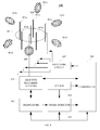
- FIG. 11 illustrates simulated results of the performance of one embodiment of a beamforming antenna system 400 in accordance with various aspects set forth herein, wherein the results show the measured input impedance of the beamforming antenna 441 over time for a user operating a wireless device in a voice call.
- the graphical representation in its entirety is referred to by 1100.
- the number of the discrete-time sample of the measured input impedance of the beamforming antenna 441 is shown on the abscissa 1101.
- the measured input impedance of the beamforming antenna 441 is shown on the ordinate 1102.
- the graph 1103 shows the real values of the measured input impedance of the beamforming antenna 441.
- the graph 1104 shows the imaginary values of the measured input impedance of the beamforming antenna 441.
- the beamforming antenna 441 uses a half-wavelength dipole for the primary radiating element 450 and five half-wavelength dipoles for the reconfigurable parasitic elements 451a to 451e.
- Each of the five reconfigurable parasitic elements 451a to 451e are one tenth of a wavelength from the primary radiating element 450.
- the antenna gain of the primary radiating element 450 is 1.65 dB and the antenna gain of the primary radiating element coupled with one of the reconfigurable parasitic elements 451a to 451e is 4.99 dB.
- the simulation was performed at a frequency of 900 MHz.
- the primary radiating element is used to provide an omnidirectional antenna-pattern beam.
- the controller operates in real time.
- an antenna system for a wireless device can include a beamforming antenna for generating an antenna-pattern beam.
- the antenna system can also include a switching circuit, an adaptive matching network, a transceiver, a sensor, and a controller.
- the beamforming antenna can include a primary radiating element, and one or more reconfigurable parasitic elements.
- the primary radiating element can be electrically connected to the adaptive matching network, wherein the adaptive matching network can be used for matching the input impedance of the beamforming antenna.
- One or more reconfigurable parasitic elements can be electrically connected, electrically coupled, or both to the primary radiating element.
- the one or more reconfigurable parasitic elements can be electrically connected to the switching circuit, wherein the switching circuit is used to select one or more of the reconfigurable parasitic elements.
- the primary radiating element and the selected parasitic elements can cooperatively receive, transmit, or both a radio frequency signal.
- the transceiver can be electrically connected to the beamforming antenna for transmitting a signal, receiving a signal, or both.
- the sensor can be used to detect the directional alignment of the wireless device, the speed of the wireless device, the acceleration of the wireless device, or any combination thereof.
- the controller can be electrically connected to the beamforming antenna, the transceiver, the switching circuit, the adaptive matching network, the sensor, or any combination thereof to adapt the antenna-pattern beam of the beamforming antenna
- the controller can use the adaptive matching network to determine that the input impedance of the beamforming antenna is outside a tolerance. Further, the controller can recognize the environment of the wireless device using the beamforming antenna, the transceiver, the switching circuit, the adaptive matching network, the sensor, or any combination thereof. In addition, the controller can select a portion of the reconfigurable parasitic elements using the input impedance of the beamforming antenna, a predetermined observation table, the recognized environment, or any combination thereof. Also, the controller can update the beamforming antenna by electrically connecting, electrically coupling, or both the selected portion of reconfigurable parasitic elements with the primary radiating element using the switching circuit.
- the senor is an accelerometer.
- the senor is a camera lens.
Abstract
Description
- This application claims the benefit of U.S. Non-Provisional Application No.
US 12/820,902 filed June 22, 2010 - The invention generally relates to antennas and, in particular, to controlling a beamforming antenna using reconfigurable parasitic elements.
- Wireless communication systems are widely deployed to provide, for example, a broad range of voice and data-related services. Typical wireless communication systems consist of multiple-access communication networks that allow users of wireless devices to share common network resources. These networks typically require multiple-band antennas for transmitting and receiving radio frequency ("RF") signals from wireless devices to infrastructure equipment such as a base station. Examples of such networks are the global system for mobile communication ("GSM"), which operates between 890 MHz and 960 MHz; the digital communications system ("DCS"), which operates between 1,710 MHz and 1,880 MHz; the personal communication system ("PCS"), which operates between 1,850 MHz and 1,990 MHz; and the universal mobile telecommunications system ("UMTS"), which operates between 1,920 MHz and 2,170 MHz.
- Emerging and future wireless communication systems may require wireless devices and infrastructure equipment to operate new modes of communication at different frequency bands to support, for instance, higher data rates, increased functionality and more users. Examples of these emerging systems are the single carrier frequency division multiple access ("SC-FDMA") system, the orthogonal frequency division multiple access ("OFDMA") system, and other like systems. An OFDMA system is supported by various technology standards such as evolved universal terrestrial radio access ("E-UTRA"), Wi-Fi, worldwide interoperability for microwave access ("WiMAX"), wireless broadband ("WiBro"), ultra mobile broadband ("UMB"), long-term evolution ("LTE"), and other similar standards.
- Moreover, wireless devices and infrastructure equipment may provide additional functionality that requires using other wireless communication systems that operate at different frequency bands. Examples of these other systems are the wireless local area network ("WLAN") system, the IEEE 802.11b system and the Bluetooth system, which operate between 2,400 MHz and 2,484 MHz; the WLAN system, the IEEE 802.11a system and the HiperLAN system, which operate between 5,150 MHz and 5,350 MHz; the global positioning system ("GPS"), which operates at 1,575 MHz; and other like systems.
Many wireless communication systems in both government and industry require a broadband, low profile antenna. Such systems may require antennas that simultaneously support multiple frequency bands. Further, such systems may require dual polarization to support polarization diversity, polarization frequency re-use, or other similar polarization operation.
In addition, smart antennas such as beamforming antennas can be used to increase capacity, reduce co-channel and adjacent channel interference, improve range, reduce transmitted power, and mitigate multipath propagation effects in wireless communication systems. Smart antennas can direct electromagnetic RF energy in a preferred direction such as towards the antenna of a base station. A smart antenna is typically composed of multiple radiating elements that can be switched into certain configurations to shape and direct an antenna-pattern beam.
However, smart antennas can suffer from a number of limitations including performance degradation from environmental-related conditions. Such conditions can include the presence of a user or an object near the smart antenna; multipath propagation effects; the speed of the wireless device traveling through a network; and other similar effects. The impact of such environmental conditions can result in, for instance, dropped calls, increased transmit power levels, lower data rates, higher power consumption, and other similar effects. As such, it is desirable to have a smart antenna that can adapt to such environmental conditions. - In order for this disclosure to be understood and put into practice by one having ordinary skill in the art, reference is now made to exemplary embodiments as illustrated by reference to the accompanying figures. Like reference numbers refer to identical or functionally similar elements throughout the accompanying figures. The figures along with the detailed description are incorporated and form part of the specification and serve to further illustrate exemplary embodiments and explain various principles and advantages, in accordance with this disclosure, where:
-
FIG. 1 is an example of a wireless communication system. -
FIG. 2 is a block diagram illustrating one embodiment of a wireless device in accordance with various aspects set forth herein. -
FIG. 3 illustrates a block diagram of one embodiment of a beamforming antenna system for a wireless device in accordance with various aspects set forth herein. -
FIG. 4 illustrates a block diagram of another embodiment of a beamforming antenna system for a wireless device in accordance with various aspects set forth herein. -
FIG. 5 illustrates a block diagram of another embodiment of a beamforming antenna system for a wireless device in accordance with various aspects set forth herein. -
FIG. 6 is a flow chart of one embodiment of a method of adapting a beamforming antenna using reconfigurable parasitic elements in accordance with various aspects set forth herein. -
FIG. 7 is a flow chart of another embodiment of a method of adapting a beamforming antenna using reconfigurable parasitic elements in accordance with various aspects set forth herein. -
FIG. 8 is a flow chart of another embodiment of a method of adapting a beamforming antenna using reconfigurable parasitic elements in accordance with various aspects set forth herein. -
FIG. 9 is a flow chart of another embodiment of a method of adapting a beamforming antenna using reconfigurable parasitic elements in accordance with various aspects set forth herein. -
FIG. 10 illustrates a block diagram of another embodiment of a beamforming antenna system for a wireless device in accordance with various aspects set forth herein. -
FIG. 11 illustrates simulated results of the performance of one embodiment of a beamforming antenna system in accordance with various aspects set forth herein. - Skilled artisans will appreciate that elements in the accompanying figures are illustrated for clarity, simplicity and to further help improve understanding of the exemplary embodiments, and have not necessarily been drawn to scale.
- Although the following discloses exemplary methods, devices and systems for use in wireless communication systems, it will be understood by one of ordinary skill in the art that the teachings of this disclosure are in no way limited to the exemplary embodiments shown. On the contrary, it is contemplated that the teachings of this disclosure may be implemented in alternative configurations and environments. For example, although the exemplary methods, devices and systems described herein are described in conjunction with a configuration for aforementioned wireless communication systems, those of ordinary skill in the art will readily recognize that the exemplary methods, devices and systems may be used in other wireless communication systems and may be configured to correspond to such other systems as needed. Accordingly, while the following describes exemplary methods, devices and systems of use thereof, persons of ordinary skill in the art will appreciate that the disclosed exemplary embodiments are not the only way to implement such methods, devices and systems, and the drawings and descriptions should be regarded as illustrative in nature and not restrictive.
- Various techniques described herein can be used for various wireless communication systems. The various aspects described herein are presented as methods, devices and systems that can include a number of components, elements, members, modules, peripherals, or the like. Further, these methods, devices and systems can include or not include additional components, elements, members, modules, peripherals, or the like. It is important to note that the terms "network" and "system" can be used interchangeably. Relational terms described herein such as "above" and "below", "left" and "right", "first" and "second", and the like may be used solely to distinguish one entity or action from another entity or action without necessarily requiring or implying any actual such relationship or order between such entities or actions. The term "or" is intended to mean an inclusive "or" rather than an exclusive "or." Further, the terms "a" and "an" are intended to mean one or more unless specified otherwise or clear from the context to be directed to a singular form. The term "electrical coupling" as described herein, which is also referred to as "capacitive coupling," "inductive coupling," or both, includes at least coupling via electric and magnetic fields, including over an electrically insulating area. The term "electrically connected" as described herein comprises at least by means of a conducting path, or through a capacitor, as distinguished from connected merely through electromagnetic induction.
- Wireless communication systems typically consist of a plurality of wireless devices and a plurality of base stations. A base station can also be referred to as a node-B ("NodeB"), a base transceiver station ("BTS"), an access point ("AP"), a satellite, a router, or some other equivalent terminology. A base station typically contains one or more RF transmitters, RF receivers, or both electrically connected to one or more antennas to communicate with a wireless devices.
- A wireless device used in a wireless communication system may also be referred to as a mobile station ("MS"), a terminal, a cellular phone, a cellular handset, a personal digital assistant ("PDA"), a smartphone, a handheld computer, a desktop computer, a laptop computer, a tablet computer, a printer, a set-top box, a television, a wireless appliance, or some other equivalent terminology. A wireless device may contain one or more RF transmitters, RF receivers or both electrically connected to one or more antennas to communicate with a base station. Further, a wireless device may be fixed or mobile and may have the ability to move through a wireless communication network.
-
FIG. 1 is a block diagram of awireless communication system 100 in accordance with various aspects described herein. In one embodiment, thesystem 100 can include awireless device 101, abase station 102, asatellite 125, anaccess point 126, anotherwireless device 127, or any combination thereof. Thewireless device 101 can include aprocessor 103, which can also be referred to as a co-processor, controller, or other similar term, electrically connected to amemory 104, input/output devices 105, atransceiver 106, a short-rangeRF communication subsystem 109, anotherRF communication subsystem 110, or any combination thereof, which can be utilized by thewireless device 101 to implement various aspects described herein. Theprocessor 103 can manage and control the overall operation of thewireless device 101. Thetransceiver 106 of thewireless device 101 can include atransmitter 107, areceiver 108, or both. Further, associated with thewireless device 101, thetransmitter 107, thereceiver 108, the short-rangeRF communication subsystem 109, the otherRF communication subsystem 110, or any combination thereof can be electrically connected to anantenna 141. - In the current embodiment, the
wireless device 101 can be capable of two-way voice communication, two-way data communication, or both including with thebase station 102, thesatellite 125, theaccess point 126, theother wireless device 127, or any combination thereof. The voice and data communications may be associated with the same or different networks using, for instance, the same ordifferent base stations 102. The detailed design of thetransceiver 106 of thewireless device 101 is dependent on the wireless communication system used. When thewireless device 101 is operating two-way data communication with thebase station 102, a text message, for instance, can be received at theantenna 141, can be processed by thereceiver 108 of thetransceiver 106, and can be provided to theprocessor 103. - In
FIG. 1 , the short-rangeRF communication subsystem 109 may also be integrated in thewireless device 101. For example, the short-rangeRF communication subsystem 109 may include a Bluetooth module, a WLAN module, or both. The short-rangeRF communication subsystem 109 may use theantenna 141 for transmitting RF signals, receiving RF signals, or both. The Bluetooth module can use theantenna 141 to communicate, for instance, with theother wireless devices 127 such as a Bluetooth-capable printer. Further, the WLAN module may use theantenna 141 to communicate with theaccess point 126 such as a router or other similar device. - In addition, the other
RF communication subsystem 110 may be integrated inwireless device 101. For example, the otherRF communication subsystem 110 may include a GPS receiver that uses theantenna 141 of thewireless device 101 to receive information from one ormore GPS satellites 125. Further, the otherRF communication subsystem 110 may use theantenna 141 of thewireless device 101 for transmitting RF signals, receiving RF signals, or both. - Similarly, the
base station 102 can include aprocessor 113 electrically connected to amemory 114 and atransceiver 116, which can be utilized by thebase station 102 to implement various aspects described herein. Thetransceiver 116 of thebase station 102 can include atransmitter 117, areceiver 118, or both. Further, associated withbase station 102, atransmitter 117, areceiver 118, or both can be electrically connected to anantenna 121. - In
FIG. 1 , thebase station 102 can communicate with thewireless device 101 on the uplink using theantennas antennas wireless device 101 and thebase station 102, respectively. The uplink refers to communication from a wireless device to a base station, while the downlink refers to communication from a base station to a wireless device. In one embodiment, thebase station 102 can originate downlink information using thetransmitter 117 and theantenna 121, where it can be received by thereceiver 108 at thewireless device 101 using theantenna 141. Such information can be related to a communication link between thebase station 102 and thewireless device 101. Once such information is received by thewireless device 101 on the downlink, thewireless device 101 can process the received information to generate a response relating to the received information. Such response can be transmitted back from thewireless device 101 on the uplink using thetransmitter 107 and theantenna 141, and received at thebase station 102 using theantenna 121 and thereceiver 118. -
FIG. 2 is a block diagram illustrating one embodiment of a wireless device 200 in accordance with various aspects set forth herein. InFIG. 2 , the wireless device 200 can include aprocessor 203 electrically connected to, for instance, atransceiver 205, adecoder 206, anencoder 207, amemory 204, anavigation mechanism 211, adisplay 212, anemitter 213, adisplay overlay 214, adisplay controller 216, a touch-sensitive display 218, anactuator 220, asensor 223, an auxiliary input/output subsystem 224, adata port 226, aspeaker 228, amicrophone 230, a short-range communication subsystem 209, anotherRF communication subsystem 210, a subscriber identity module or a removable user identity module ("SIM/RUIM")interface 240, abattery interface 242, other component, or any combination thereof. Thenavigation mechanism 211 can be, for instance, a trackball, a directional pad, a trackpad, a touch-sensitive display, a scroll wheel, or other similar navigation mechanism. - In
FIG. 2 , theprocessor 203 can control and perform various functions associated with the control, operation, or both of the wireless device 200. The wireless device 200 can be powered by, for instance, thebattery 244, an alternating current ("AC") source, another power source, or any combination thereof. InFIG 2 , the wireless device 200 can use, for instance, thebattery interface 242 to receive power from thebattery 244. Thebattery 244 can be, for instance, a rechargeable battery, a replaceable battery, or both. Theprocessor 203 can control thebattery 244 via thebattery interface 242. - In this embodiment, the wireless device 200 can perform communication functions, including data communication, voice communication, video communication, other communication, or any combination thereof using, for instance, the
processor 203 electrically connected to the auxiliary input/output subsystem 224, thedata port 226, thetransceiver 205, the short-range communication subsystem 209, the otherRF communication subsystem 210, or any combination thereof. The wireless device 200 can communicate between, for instance, thenetwork 250. Thenetwork 250 may be comprised of, for instance, a plurality of wireless devices and a plurality of infrastructure equipment. - In
FIG. 2 , thedisplay controller 216 can be electrically connected to thedisplay overlay 214,display 212, or both. For example, thedisplay overlay 214 and thedisplay 212 can be electrically connected to thedisplay controller 216 to form, for instance, the touch-sensitive display 218. The touch-sensitive display 218 can also be referred to as a touch-screen display, touch-screen monitor, touch-screen terminal, or other similar term. Theprocessor 203 can directly controldisplay overlay 214, indirectly controldisplay overlay 214 usingdisplay controller 216, or both. Theprocessor 203 can display, for instance, an electronic document stored in thememory 210 on thedisplay 212, the touch-sensitive display 218, or both of the wireless device 200. - In the current embodiment, the wireless device 200 can include the
sensor 223, which can be electrically connected to theprocessor 203. Thesensor 223 can be, for instance, an accelerometer sensor, a tilt sensor, a force sensor, an optical sensor, or any combination thereof. Further, thesensor 223 may comprise multiple sensors which are the same or different. For example, thesensor 223 can include an accelerometer sensor and an optical sensor. An accelerometer sensor may be used, for instance, to detect the direction of gravitational forces, gravity-induced reaction forces, or both. Further, the accelerometer sensor may be used to detect the placement of the wireless device 200 in various directional alignments such as a horizontal directional alignment. The accelerometer sensor may include, for instance, a cantilever beam with a proof mass and suitable deflection sensing circuitry. The optical sensor can be the same or similar to the sensor used in, for instance, a desktop mouse. Alternatively, the optical sensor can be, for instance, a camera lens. Theprocessor 203 may be configured to process contiguous images captured by the camera lens and use such images to detect the direction, distance, or both of thewireless device 100 relative to an object, surface, or user. For instance, theprocessor 203 may be configured to process contiguous images captured by the camera lens and use such images to detect a user of the wireless device 200 placing such device, for instance, against the user's ear. - In
FIG. 2 , the wireless device 200 may include the subscriber identity module or a removable user identity module ("SIM/RUIM")card 238. The SIM/RUIM card 238 can contain, for instance, user identification information, which can be used to allow access to network 250 for the user of the wireless device 200. The SIM/RUIM card 238 can be electrically connected to the SIM/RUIM interface 240, wherein theprocessor 203 can control the SIM/RUIM card 238 via the SIM/RUIM interface 240. The user identification information may also be stored in thememory 204 and accessed by theprocessor 203. - In this embodiment, the wireless device 200 can include an
operating system 246 andsoftware modules 248, which may be stored in a computer-readable medium such as thememory 204. Thememory 204 can be, for instance, RAM, static RAM ("SRAM"), dynamic RAM ("DRAM"), read only memory ("ROM"), volatile memory, non-volatile memory, cache memory, hard drive memory, virtual memory, other memory, or any combination thereof. Theprocessor 203 can execute program instructions stored in thememory 204 associated with theoperating system 246, thesoftware modules 248, other program instructions, or combination of program instructions. Theprocessor 203 may load theoperating system 246, thesoftware modules 248, data, an electronic document, or any combination thereof into thememory 204 via thetransceiver 205, the auxiliary I/O subsystem 224, thedata port 226, the short-rangeRF communications subsystem 209, the otherRF communication subsystem 210, or any combination thereof. -
FIG. 3 illustrates a block diagram of one embodiment of abeamforming antenna system 300 for a wireless device in accordance with various aspects set forth herein. InFIG. 3 , thesystem 300 can include abeamforming antenna 341, anadaptive matching network 342, atransceiver 305, ausage detector 344, asensor 323, acontroller 303, aswitching circuit 347, other element, or any combination thereof. Thebeamforming antenna 341 can include a primary radiating element with one or more reconfigurable parasitic elements. Thebeamforming antenna 341 can shape and direct an electromagnetic antenna-pattern beam radiated from thebeamforming antenna 341 to, for instance, improve the quality of a transmitted signal, received signal, or both. For example, thebeamforming antenna 341 can adaptively steer the antenna-pattern beam towards a base station while traveling throughout the coverage area of such base station. Further, thebeamforming antenna 341 can direct the antenna-pattern beam away from a user of the associated wireless device to reduce the amount of electromagnetic energy absorbed by such user. Also, by directing the antenna-pattern beam of thebeamforming antenna 341 towards a receiving antenna such as at a base station can reduce the amount of co-channel or adjacent channel interference received by other wireless devices. By more effectively and efficiently receiving RF signals, radiating RF signals, or both, the wireless device using thebeamforming antenna 341 can achieve better performance with lower average power consumption. - In
FIG. 3 , the steering of the antenna-pattern beam can be performed using, for instance, switching elements associated with theswitching circuit 347 to select reconfigurable parasitic elements of thebeamforming antenna 341. The selected parasitic elements and the primary radiating element can cooperatively receive and radiate RF signals. Thebeamforming antenna 341 can be electrically connected to theadaptive matching network 342, which can be used in, for instance, real time, near-real time, non-real time, periodically, aperiodically, or any combination thereof to match the input impedance of thebeamforming antenna 341 to improve the power transfer and reduce reflections from thebeamforming antenna 341. Further, theadaptive matching network 342 can be used in, for instance, real time, near-real time, non-real time, periodically, aperiodically, or any combination thereof to estimate the input impedance of thebeamforming antenna 341. Thetransceiver 305 can include a transmitter, a receiver, or both. The input to thetransceiver 305 can be an RF signal, which has been converted from an electromagnetic signal to an electrical signal via thebeamforming antenna 341. The output of thetransceiver 305 can be a baseband signal or an intermediate frequency ("IF") signal. On the downlink, the input to thetransceiver 305 can be an RF signal, which can be converted from an electromagnetic signal to an electrical signal via thebeamforming antenna 341. The output of thetransceiver 305 can be a baseband signal or an intermediate frequency ("IF") signal. Similarly, on the uplink, the input to thetransceiver 305 can be a baseband signal or an IF signal. The output of thetransceiver 305 can be an RF signal, which can be converted from an electrical signal to an electromagnetic signal by thebeamforming antenna 341. The detailed design of thetransceiver 305 is dependent on, for instance, the wireless communication system used. - In the current embodiment, the
usage detector 344 can be used to determine, for instance, the orientation, the operating mode, the operating environment, or any combination thereof of the wireless device, which may be used to determine to update thebeamforming antenna 341, adapt the antenna-pattern beam of thebeamforming antenna 341, or both. Theusage detector 344 can receive, for instance, a signal from theadaptive matching network 342, a signal from thetransceiver 305, a signal from thesensor 323, other signal, or any combination thereof. Theusage detector 344 can determine the operating environment of the wireless device by identifying a change in, for instance, the received signal strength of thebeamforming antenna 341; the directional alignment of the wireless device using, for instance, an accelerometer; the propagation characteristics of a received signal; the input impedance of thebeamforming antenna 341; other information; or any combination thereof. - For instance, the
usage detector 344 can determine that the wireless device is placed against a user's ear during a voice call using the call processing state of the wireless device, the directional alignment of the wireless device, a change in the input impedance of thebeamforming antenna 341, other factor, or any combination thereof. For example, theusage detector 344 can receive a signal from thesensor 323 indicating that the wireless device is in a substantially horizontal directional alignment consistent with the positioning of the wireless device by a user during a voice call. Further, thecontroller 303 can provide theusage detector 344 with, for instance, the call processing state of the wireless device such as a voice call state. In addition, theusage detector 344 can monitor for a change in the input impedance of thebeamforming antenna 341 using theadaptive matching network 342, which may be used to determine, for instance, that a wireless device is close to the user's body. After determining, for instance, that the wireless device is placed against a user's ear during a voice call, thecontroller 303 can switch one or more reconfigurable parasitic elements of thebeamforming antenna 341 to steer the antenna-pattern beam away from the user's body. - In
FIG. 3 , thecontroller 303 can determine to update the antenna-pattern beam of thebeamforming antenna 341 by using, for instance, a change in the received signal strength of thebeamforming antenna 341, the directional alignment of the wireless device, the propagation characteristics of a received signal via thebeamforming antenna 341, the input impedance of thebeamforming antenna 341 using theadaptive matching network 342, or any combination thereof. In another embodiment, thecontroller 303 can measure a plurality of received signal strengths of thebeamforming antenna 341, wherein each measurement can correspond to the primary radiating element with one or more different reconfigurable parasitic elements. Further, thecontroller 303 can determine to steer thebeamforming antenna 341 by, for instance, comparing one or more of such received signal strengths to the received signal strength of the currently configured beamforming antenna. -
FIG. 4 illustrates a block diagram of another embodiment of abeamforming antenna system 400 for a wireless device in accordance with various aspects set forth herein. InFIG. 4 , thesystem 400 can include abeamforming antenna 441, anadaptive matching network 442, atransceiver 405, ausage detector 444, asensor 423, acontroller 403, aswitching circuit 447, other element, or any combination thereof. Thebeamforming antenna 441 can include aprimary radiating element 450 with one or more secondaryparasitic elements 451a to 451e. In this embodiment, theprimary radiating element 450 is a dipole. Further, there are five reconfigurable parasitic elements, wherein each of the reconfigurableparasitic elements 451a to 451e is a dipole. In another embodiment, the primary radiating element and the reconfigurable parasitic elements are monopoles. It is important to recognize that the primary radiating element and any combination of the reconfigurable parasitic elements form a beamforming antenna, which can radiate with specific characteristics. Further, the primary radiating element and any combination of the reconfigurable parasitic elements can be electrically connected, electrically coupled, or both. Therefore, the primary radiating element and any combination of the reconfigurable parasitic elements can be physically connected or not physically connected. - In one definition, a dipole antenna, is an omnidirectional radio antenna with a center-fed driven element, which can be made of, for instance, a simple copper wire. Further, in one definition, a monopole antenna is an omnidirectional antenna formed by replacing one half of a dipole antenna with a ground plane at a substantially perpendicular angle to the monopole, wherein the monopole can behave like a dipole if the ground plane is sufficiently large. The length of a radiating element such as a monopole can typically be as short as about one-quarter the wavelength of the desired resonant frequency. One skilled in the art will appreciate that the length of a radiating element of the present disclosure is not limited to one-quarter the wavelength of the desired resonant frequency, but other lengths may be chosen, such as one-half the wavelength of the desired resonant frequency. Similarly, the length of a radiating element such as a dipole can typically be as short as about one-half the wavelength of the desired resonant frequency.
- The
beamforming antenna 441 can direct an electromagnetic antenna-pattern beam 461a to 461e radiated from thebeamforming antenna 441 to improve the quality of a transmitted signal, received signal, or both. Thebeamforming antenna 441 can adaptively steer the antenna-pattern beam 461a to 461e towards, for instance, a base station while traveling throughout the coverage area of the base station. For example, thecontroller 403 selects theparasitic element 451a. In such configuration, theprimary radiating element 450 and theparasitic element 451a cooperatively transmit an antenna-pattern beam in the direction consistent with the antenna-pattern beam 461a. In another example, thecontroller 403 does not select any reconfigurableparasitic elements 451a to 451e. In such configuration, theprimary radiating element 450 provides an omnidirectional beam. In another example, thecontroller 403 selects the reconfigurableparasitic elements 451a and 451b. In such configuration, theprimary radiating element 450 and the reconfigurableparasitic elements 451a and 451b provide an antenna-pattern beam in the direction between the antenna-pattern beams 461a and 461b. Further, thebeamforming antenna 441 can direct the antenna-pattern beam 461a to 461e away from a user of the associated wireless device to reduce the amount of electromagnetic energy absorbed by such user. Also, by directing the antenna-pattern beam 461a to 461e of thebeamforming antenna 441 towards a receiving antenna such as at a base station can reduce the amount of interference received by other wireless devices. By more effectively and efficiently receiving RF signals, radiating RF signals, or both, the wireless device using thebeamforming antenna 441 can achieve better performance and lower power consumption. It is important to recognize any combination of reconfigurable parasitic elements can be used in conjunction with the primary radiating element. Further, any number of primary and reconfigurable parasitic elements can be used. For example, two primary radiating elements can be used to provide, for instance, polarization diversity. Further, six reconfigurable parasitic elements can be used in conjunction with the two primary radiating elements to cooperatively provide an antenna-pattern beam in a predetermined direction. - In
FIG. 4 , the adaptive steering of the antenna-pattern beam can be performed using, for instance, switching elements associated with theswitching circuit 447 to selectparasitic elements 451a and 451b of thebeamforming antenna 441. The selectedparasitic elements 451a and 451b and theprimary radiating element 450 can cooperatively receive and radiate RF signals. For example, a plurality of reconfigurableparasitic elements 451a and 451b such as monopoles, dipoles, or both can be contiguously and uniformly distributed around aprimary radiating element 450. Suchparasitic elements 451a and 451b can be adaptively switched to cooperatively work with theprimary radiating element 450 to adaptively steer the antenna-pattern beam. It is important to recognize that the beamforming antenna configurations described by this disclosure may also provide polarization diversity, frequency diversity, multiband operation, broadband operation, or any combination thereof. Further, a person of ordinary skill in the art will recognize that there are many different antenna systems, structures, and configurations, which may support a beamforming function as described in this disclosure. - In the current embodiment, the
beamforming antenna 441 can be electrically connected to theadaptive matching network 442, which can be used to match the input impedance of thebeamforming antenna 441, for instance, after switching to the desired parasitic element or elements is made to improve the power transfer and reduce reflections from thebeamforming antenna 441. Further, theadaptive matching network 442 can be used to estimate the input impedance of thebeamforming antenna 441. Thetransceiver 405 can include a transmitter, a receiver, or both. On the downlink, the input to thetransceiver 405 can be an RF signal, which can be converted from an electromagnetic signal to an electrical signal via thebeamforming antenna 441. The output of thetransceiver 405 can be a baseband signal or an intermediate frequency ("IF") signal. Similarly, on the uplink, the input to thetransceiver 405 can be a baseband signal or an IF signal. The output of thetransceiver 405 can be an RF signal, which can be converted from an electrical signal to an electromagnetic signal by thebeamforming antenna 441. The detailed design of thetransceiver 405 is dependent on the wireless communication system used. - In
FIG. 4 , theusage detector 444 can be used to determine the operating environment of the wireless device, which may be used to further adapt or control the antenna-pattern beam of thebeamforming antenna 441. Theusage detector 444 can receive a signal from theadaptive matching network 442, a signal from thetransceiver 405, a signal from thesensor 423, other signal, or any combination thereof. Theusage detector 444 can determine the operating environment of the wireless device by identifying a change in, for instance, the received signal strength of thebeamforming antenna 441; the directional alignment of the wireless device; the propagation characteristics of a received signal; the input impedance of thebeamforming antenna 441; other information; or any combination thereof. - For instance, the
usage detector 444 can determine that the wireless device is placed against a user's ear during a voice call using the call processing state of the wireless device, the directional alignment of the wireless device, a change in the input impedance of thebeamforming antenna 441, other factor, or any combination thereof. For example, theusage detector 444 can receive a signal from thesensor 423 indicating that the wireless device is in a substantially horizontal directional alignment consistent with the positioning of the wireless device by a user during a voice call. Further, thecontroller 403 can provide theusage detector 444 with, for instance, the call processing state of the wireless device such as a voice call state. In addition, theusage detector 444 can monitor for a change in the input impedance of thebeamforming antenna 441 using theadaptive matching network 442, which may be used to determine, for instance, that a wireless device is close to the user's body. After determining that the wireless device is placed against a user's ear during a voice call, thecontroller 403 can switch one or more reconfigurableparasitic elements 451a and 451b of thebeamforming antenna 441 to steer the antenna-pattern beam away from the user's body. - In
FIG. 4 , thecontroller 403 can determine to update the antenna-pattern beam of thebeamforming antenna 441 by using, for instance, a change in the received signal strength of thebeamforming antenna 441; the directional alignment of the wireless device; the propagation characteristics of a received signal via thebeamforming antenna 441; the input impedance of thebeamforming antenna 441 using theadaptive matching network 442; or any combination thereof. In another embodiment, thecontroller 403 can measure a plurality of received signal strengths for thebeamforming antenna 441, wherein each measurement can correspond to theprimary radiating element 450 with one or more different reconfigurableparasitic elements 451a and 451b. Further, thecontroller 403 can determine to adaptively steer thebeamforming antenna 441 by, for instance, comparing one or more of such received signal strengths to the received signal strength of the currently configured beamforming antenna. If one or more of such received signal strengths is sufficiently greater than the received signal strength of the currently configured beamforming antenna, then thecontroller 403 can switch to the one or more reconfigurableparasitic elements 451a and 451b corresponding to the greater received signal strength by using theswitching circuit 447. -
FIG. 5 illustrates a block diagram of another embodiment of abeamforming antenna system 500 for a wireless device in accordance with various aspects set forth herein. InFIG. 5 , thesystem 500 can include abeamforming antenna 541, anadaptive matching network 542, atransceiver 505, ausage detector 544, asensor 523, acontroller 503, aswitching circuit 547, other element, or any combination thereof. Thebeamforming antenna 541 can include aprimary radiating element 552 with one or more reconfigurableparasitic elements 553a to 553e. In this embodiment, theprimary radiating element 552 is a patch antenna. Further, each of the reconfigurableparasitic elements 553a to 553e is a radiating strip or patch element. - A patch antenna typically is a miniaturized antenna radiating structure, such as a planar inverted-F antenna ("PIFA"). Patch antennas are popular for use in wireless devices due to their low profile, ability to conform to surface profiles, and unlimited shapes and sizes. Patch antenna polarization can be linear or elliptical, with a main polarization component parallel to the surface of the patch antenna. Operating characteristics of patch antennas are predominantly established by their shape and dimensions. The patch antenna is typically fabricated using printed-circuit techniques and integrated with a printed circuit board ("PCB"). The patch antenna is typically electrically coupled to a ground area, wherein the ground area is typically formed on or in a PCB. Patch antennas are typically spaced from and parallel to the ground area and are typically located near other electronic components, ground planes, and signal traces, which may impact the design and performance of the antenna. In addition, patch antennas are typically considered to be lightweight, compact, and relatively easy to manufacture and integrate into a wireless device.
- A patch antenna design can include one or more slots in the antenna's radiating member. Selection of the position, shape, contour, and length of a slot depends on the design requirements of the particular patch antenna. The function of a slot in a patch antenna design includes physically partitioning the radiating member of a single-band patch antenna into a subset of radiating members for multiple-band operation, providing reactive loading to modify the resonant frequencies of a radiating member, and controlling the polarization characteristics of a multiple-band patch antenna. In addition to a slot, radiating members of a patch antenna can have stub members, usually consisting of a tab at the end of a radiating member. The function of a stub member includes providing reactive loading to modify the resonant frequencies of a radiating member.
- The
beamforming antenna 541 can direct an electromagnetic beam radiated from thebeamforming antenna 541 to improve the quality of a transmitted signal, received signal, or both. For example, thebeamforming antenna 541 can steer the antenna-pattern beam towards a base station while traveling throughout the coverage area of the base station. Further, thebeamforming antenna 541 can direct the antenna-pattern beam away from a user of the associated wireless device to reduce the amount of electromagnetic energy absorbed by such user. Also, by directing the antenna-pattern beam of thebeamforming antenna 541 towards a receiving antenna such as at a base station can reduce the amount of interference received by other wireless devices. By more effectively and efficiently receiving RF signals, radiating RF signals, or both, the wireless device using thebeamforming antenna 541 can achieve lower power consumption. - In
FIG. 5 , the steering of the antenna-pattern beam can be performed using, for instance, switching elements associated with theswitching circuit 547 to select reconfigurable parasitic elements of thebeamforming antenna 541. The selected parasitic elements and the primary radiating element can cooperatively receive and radiate RF signals. For example, a plurality of radiatingstrip elements 553a to 553e can be adaptively switched to cooperatively work with thepatch antenna 552 to steer the antenna-pattern beam. It is important to recognize that the aforementioned beamforming antenna configurations may also provide polarization diversity, frequency diversity, multiband operation, broadband operation, or any combination thereof. - In the current embodiment, the
beamforming antenna 541 can be electrically connected to theadaptive matching network 542, which can be used to match the input impedance of thebeamforming antenna 541 to improve the power transfer and reduce reflections from thebeamforming antenna 541. Further, theadaptive matching network 542 can be used to estimate the input impedance of thebeamforming antenna 541. Thetransceiver 505 can include a transmitter, a receiver, or both. On the downlink, the input to thetransceiver 505 can be an RF signal, which can be converted from an electromagnetic signal to an electrical signal via thebeamforming antenna 541. The output of thetransceiver 505 can be a baseband signal or an intermediate frequency ("IF") signal. Similarly, on the uplink, the input to thetransceiver 505 can be a baseband signal or an IF signal. The output of thetransceiver 505 can be an RF signal, which can be converted from an electrical signal to an electromagnetic signal by thebeamforming antenna 541. The detailed design of thetransceiver 505 is dependent on the wireless communication system used. - In
FIG. 5 , theusage detector 544 can be used to determine the operating environment of the wireless device, which may be used to further adapt the antenna-pattern beam of thebeamforming antenna 541. Theusage detector 544 can receive a signal from theadaptive matching network 542, a signal from thetransceiver 505, a signal from thesensor 523, other signal, or any combination thereof. Theusage detector 544 can determine the operating environment of the wireless device by identifying a change in, for instance, the received signal strength of thebeamforming antenna 541; the directional alignment of the wireless device, the propagation characteristics of a received signal; the input impedance of thebeamforming antenna 541; other information; or any combination thereof. - For instance, the
usage detector 544 can determine that the wireless device is placed against a user's ear during a voice call using the call processing state of the wireless device, the directional alignment of the wireless device, a change in the input impedance of thebeamforming antenna 541, other factor, or any combination thereof. For example, theusage detector 544 can receive a signal from thesensor 523 indicating that the wireless device is in a substantially horizontal directional alignment consistent with the positioning of the wireless device by a user during a voice call. Further, thecontroller 503 can provide theusage detector 544 with, for instance, the call processing state of the wireless device such as a voice call state. In addition, theusage detector 544 can monitor for a change in the input impedance of thebeamforming antenna 541 using theadaptive matching network 542, which may be used to, for instance, initiate the adaptive beam steering operation after determining that a wireless device is close to the user's body. After determining that the wireless device is placed against a user's ear during a voice call, thecontroller 503 can switch one or moreradiating strip elements 553a to 553e of thebeamforming antenna 541 to steer the antenna-pattern beam away from the user's body. - In
FIG. 5 , thecontroller 503 can determine to update the antenna-pattern beam of thebeamforming antenna 541 by using, for instance, a change in the received signal strength of thebeamforming antenna 541, the directional alignment of the wireless device, the propagation characteristics of a received signal via thebeamforming antenna 541, the input impedance of thebeamforming antenna 541 using theadaptive matching network 542, or any combination thereof. In another embodiment, thecontroller 503 can measure a plurality of received signal strengths for thebeamforming antenna 541, wherein each measurement can correspond to the primary radiating element with one or more different reconfigurable parasitic elements. Further, thecontroller 503 can determine to steer thebeamforming antenna 541 by, for instance, comparing one or more of such received signal strengths to the received signal strength of the currently configured beamforming antenna. -
FIG. 6 is a flow chart of one embodiment of amethod 600 of adapting a beamforming antenna using reconfigurable parasitic elements in accordance with various aspects set forth herein. InFIG. 6 , themethod 600 can start atblock 681, where themethod 600 can calculate the input impedance of the beamforming antenna using an adaptive matching network, wherein the adaptive matching network is electrically connected to the beamforming antenna. Atblock 682, themethod 600 can determine whether the input impedance of the beamforming antenna is outside a tolerance. The tolerance can reflect the variability of the input impedance of the beamforming antenna while in a static environment. For instance, the tolerance can be correlated to the variance of the input impedance of the beamforming antenna while in a specific environment. The quality of the design of the beamforming antenna, the quality of the components used for the beamforming antenna, environmental conditions, other factor, or any combination thereof may impact the tolerance of the beamforming antenna. - If the input impedance is outside the tolerance of the beamforming antenna, at
block 683, themethod 600 can determine the operating environment of the wireless device using, for instance, the received signal strength of the beamforming antenna, the propagation characteristics of a received signal via the beamforming antenna, the input impedance of the beamforming antenna, the speed of the wireless device, the delay spread of signals received at the beamforming antenna, the directional alignment of the wireless device, other factor, or any combination thereof. Themethod 600 can use a sensor such as an accelerometer to determine, for instance, the directional alignment of the wireless device, the speed of the wireless device, the acceleration of the wireless device, other factor, or any combination thereof. In another embodiment, themethod 600 can use a sensor such as a camera to monitor contiguous images to determine whether the wireless device is placed against or near a user's ear. - In
FIG. 6 , atblock 684, themethod 600 can select a set of one or more reconfigurable parasitic elements using, for instance, the input impedance, a predetermined input impedance observation table, the recognized operating environment, other factor, or any combination thereof. For example, themethod 600 can compare the measured input impedance of the beamforming antenna to entries in the predetermined input impedance observation table to select one or more reconfigurable parasitic elements. The predetermined input impedance observation table can be derived by capturing the measurements of the input impedance of the beamforming antenna under various environments and conditions. The various environments and conditions can be, for instance, the presence of a user or an object near the beamforming antenna of a wireless device; an RF signal transmitted from a specific direction towards the beamforming antenna of a wireless device; the propagation environment; other condition or environment; or any combination thereof. Atblock 689, themethod 600 can update the beamforming antenna by electrically connecting, electrically coupling, or both the set of one or more reconfigurable parasitic elements with the primary radiating element. The input impedance matching of the beamforming antenna formed by the primary radiating element electrically connected, electrically coupled, or both to one or more selected parasitic elements can be adaptively optimized for maximum power transfer using the calculated impedance value. -
FIG. 7 is a flow chart of one embodiment of amethod 700 of adapting a beamforming antenna using reconfigurable parasitic elements in accordance with various aspects set forth herein. InFIG. 7 , themethod 700 can start atblock 781, where themethod 700 can calculate the input impedance of the beamforming antenna using an adaptive matching network, wherein the adaptive matching network is electrically connected to the beamforming antenna. Atblock 782, themethod 700 can determine whether the input impedance of the beamforming antenna is outside a tolerance. The tolerance can reflect the variability of the input impedance of the beamforming antenna while in, for instance, a static environment. For example, the tolerance can be correlated to the variance of the input impedance of the beamforming antenna while in a specific environment. The quality of the design of the beamforming antenna, the quality of the components used for the beamforming antenna, environmental conditions, other factor, or any combination thereof may impact the tolerance of the beamforming antenna. - If the input impedance is outside the tolerance of the beamforming antenna, at
block 783, themethod 700 can determine the operating environment of the wireless device using, for instance, the received signal strength of the beamforming antenna, the propagation characteristics of a received signal via the beamforming antenna, the input impedance of the beamforming antenna, the speed of the wireless device, the delay spread of signals received at the beamforming antenna, the directional alignment of the wireless device, other factor, or any combination thereof. Themethod 700 can use a sensor such as an accelerometer to determine, for instance, the directional alignment of the wireless device, the speed of the wireless device, the acceleration of the wireless device, other factor, or any combination thereof. In another embodiment, themethod 700 can use a sensor such as a camera to monitor contiguous images to determine whether the wireless device is placed against or near a user's ear. - In
FIG. 7 , atblock 784, themethod 700 can select a portion of one or more reconfigurable parasitic elements using, for instance, the input impedance, a predetermined input impedance observation table, the recognized operating environment, other factor, or any combination thereof. For example, themethod 700 can compare the measured input impedance of the beamforming antenna to entries in the predetermined input impedance observation table to select one or more reconfigurable parasitic elements. The predetermined input impedance observation table can be derived by capturing the measurements of the input impedance of the beamforming antenna under various environments and conditions. The various environments and conditions can be, for instance, the presence of a user or an object; an RF signal transmitted from a specific direction towards the beamforming antenna; the propagation environment; other condition; or any combination thereof. - At
block 785, themethod 700 can calculate the input impedance of the beamforming antenna for each of the portion of reconfigurable parasitic elements using the adaptive matching network. Atblock 786, themethod 700 can determine whether to consider more than one parasitic element configuration using the input impedance calculated atblock 785. If more than one parasitic element configuration is considered, then atblock 787 themethod 700 can calculate the received signal strength of the beamforming antenna for the primary radiating element with any combination of the parasitic element configurations. Atblock 788, themethod 700 can select one or more of the parasitic element configurations having the largest received signal strength. Atblock 789, themethod 700 can update the beamforming antenna by electrically connecting, electrically coupling, or both the selected parasitic element configuration or configurations with the primary radiating element by using, for instance, a switching circuit. The input impedance match of the antenna formed by the primary radiating element electrically connected, electrically coupled, or both to one or more of the selected parasitic elements can be adaptively updated to improve the power transfer of the beamforming antenna by using the adaptive matching network to calculate the input impedance value. -
FIG. 8 is a flow chart of another embodiment of amethod 800 of adapting a beamforming antenna using reconfigurable parasitic elements in accordance with various aspects set forth herein. InFIG. 8 , themethod 800 can start atblock 881, where themethod 800 can calculate the input impedance of the beamforming antenna using an adaptive matching network, wherein the adaptive matching network is electrically connected to the beamforming antenna. Atblock 882, themethod 800 can determine whether the input impedance of the beamforming antenna is outside a tolerance. The tolerance can reflect the variability of the input impedance of the beamforming antenna while in a static environment. For instance, the tolerance can be correlated to the variance of the input impedance of the beamforming antenna while in a specific environment. The quality of the design of the beamforming antenna, the quality of the components used for the beamforming antenna, environmental conditions, other factor, or any combination thereof may impact the tolerance of the beamforming antenna. - If the input impedance is outside the tolerance of the beamforming antenna, at
block 883, themethod 800 can determine the operating environment of the wireless device using, for instance, the received signal strength of the beamforming antenna, the propagation characteristics of a received signal via the beamforming antenna, the input impedance of the beamforming antenna, the speed of the wireless device, the delay spread of signals received at the beamforming antenna, the directional alignment of the wireless device, other factor, or any combination thereof. Themethod 800 can use a sensor such as an accelerometer to determine, for instance, the directional alignment of the wireless device, the speed of the wireless device, the acceleration of the wireless device, other factor, or any combination thereof. In another embodiment, themethod 800 can use a sensor such as a camera to monitor contiguous images to determine whether the wireless device is placed against or near a user's ear. - In
FIG. 8 , atblock 884, themethod 800 can select a set of one or more reconfigurable parasitic elements using, for instance, the input impedance, a predetermined input impedance observation table, the recognized operating environment, other factor, or any combination thereof. For example, themethod 800 can compare the measured input impedance of the beamforming antenna to entries in the predetermined input impedance observation table to select one or more reconfigurable parasitic elements. The predetermined input impedance observation table can be derived by capturing the measurements of the input impedance of the beamforming antenna under various environments and conditions. The various environments and conditions can be, for instance, the presence of a user or an object; an RF signal transmitted from a specific direction towards the beamforming antenna; the propagation environment of the wireless device; other condition; or any combination thereof. Atblock 889, themethod 800 can update the beamforming antenna by electrically connecting, electrically coupling, or both the set of one or more reconfigurable parasitic elements with the primary radiating element. After updating the beamforming antenna, atblock 890, themethod 800 can re-calculate the input impedance of the updated beamforming antenna using, for instance, the adaptive matching network. Atblock 891, themethod 900 can then match the adaptive matching network to about the same calculated input impedance of the updated beamforming antenna. -
FIG. 9 is a flow chart of another embodiment of amethod 900 of adapting a beamforming antenna using reconfigurable parasitic elements in accordance with various aspects set forth herein. InFIG. 9 , themethod 900 can start atblock 980, where themethod 900 can determine whether to update the beamforming antenna by, for instance, determining a change in the received signal strength of the beamforming antenna, the directional alignment of the wireless device, the propagation characteristics of a received signal via the beamforming antenna, the input impedance of the beamforming antenna, or any combination thereof. In another embodiment, themethod 900 can measure a plurality of received signal strengths of the beamforming antenna, wherein each measurement corresponds to a primary radiating element of the beamforming antenna with one or more different reconfigurable parasitic elements. Further, themethod 900 can determine to update the beamforming antenna by determining whether one of the plurality of received signal strengths corresponding to a specific configuration of one or more reconfigurable parasitic elements with the primary radiating element is greater than the received signal strength of the currently configured beamforming antenna. If one of the plurality of received signal strengths is greater than the received signal strength of the currently configured beamforming antenna, then themethod 900 can update the beamforming antenna. - At
block 981, themethod 900 can calculate the input impedance of the beamforming antenna using an adaptive matching network, wherein the adaptive matching network is electrically connected to the beamforming antenna. Atblock 982, themethod 900 can determine whether the input impedance of the beamforming antenna is outside a tolerance. The tolerance can reflect the variability of the input impedance of the beamforming antenna while in a specific environment such as a static environment. For instance, the tolerance can be correlated to the variance of the input impedance of the beamforming antenna while in a specific environment. The quality of the design of the beamforming antenna, the quality of the components used for the beamforming antenna, environmental conditions, other factor, or any combination thereof may impact the tolerance of the beamforming antenna. - If the input impedance is outside the tolerance of the beamforming antenna, at
block 983, themethod 900 can determine the operating environment of the wireless device using, for instance, the received signal strength, the propagation characteristics of the received signal, the input impedance of the beamforming antenna, the speed of the wireless device, the delay spread of signals received at the beamforming antenna, the directional alignment of the wireless device, other factor, or any combination thereof. Themethod 900 can use a sensor such as an accelerometer to determine, for instance, the directional alignment of the wireless device, the speed of the wireless device, the acceleration of the wireless device, other factor, or any combination thereof. In another embodiment, themethod 900 can use a sensor such as a camera to monitor contiguous images to determine whether the wireless device is placed against or near a user's ear. - In
FIG. 9 , atblock 984, themethod 900 can select a portion of one or more reconfigurable parasitic elements using, for instance, the measured input impedance of the beamforming antenna, a predetermined input impedance observation table, the recognized operating environment, other factor, or any combination thereof. For example, themethod 900 can compare the measured input impedance of the beamforming antenna to entries in the predetermined input impedance observation table to select the set of one or more reconfigurable parasitic elements. The predetermined input impedance observation table can be derived by capturing the measurements of the input impedance of the beamforming antenna under various environments and conditions. The various environments and conditions can be, for instance, the presence of a user or an object; an RF signal transmitted from a specific direction towards the beamforming antenna; the propagation environment of the wireless device; other condition; or any combination thereof. At block 988, themethod 900 can update the beamforming antenna by electrically connecting, electrically coupling, or both the set of one or more reconfigurable parasitic elements with the primary radiating element. -
FIG. 10 illustrates a block diagram of another embodiment of abeamforming antenna system 1000 for a wireless device in accordance with various aspects set forth herein. InFIG. 10 , thesystem 1000 can include abeamforming antenna 1041, anadaptive matching network 1042, atransceiver 1005, ausage detector 1044, asensor 1023, acontroller 1003, aswitching circuit 1047, other element, or any combination thereof. Thebeamforming antenna 1041 can include aprimary radiating element 1050 with a reconfigurableparasitic elements 1051. In this embodiment, theprimary radiating element 1050 is a monopole or a dipole, and the reconfigurableparasitic element 1051 is a monopole or a dipole. - Under normal operation of the wireless device, the beamforming antenna can use the
primary radiating element 1050 to generate an omnidirectional antenna-pattern beam 1060. When, for instance, the wireless device is placed to the user's ear, thebeamforming antenna 1041 can direct the antenna-pattern beam 1061 away from the user to reduce the amount of electromagnetic energy absorbed by such user. The directing of the antenna-pattern beam away from a user can be performed using, for instance, a switching element associated with theswitching circuit 1047 to select theparasitic element 1051 of thebeamforming antenna 1041. Theparasitic element 1051 and theprimary radiating element 1050 can cooperatively receive and radiate RF signals. - In the current embodiment, the
beamforming antenna 1041 can be electrically connected to theadaptive matching network 1042, which can be used to match the input impedance of thebeamforming antenna 1041 to improve the power transfer and reduce reflections from thebeamforming antenna 1041. Further, theadaptive matching network 1042 can be used to estimate the input impedance of thebeamforming antenna 1041. Thetransceiver 1005 can include a transmitter, a receiver, or both. On the downlink, the input to thetransceiver 1005 can be an RF signal, which can be converted from an electromagnetic signal to an electrical signal via thebeamforming antenna 1041. The output of thetransceiver 1005 can be a baseband signal or an intermediate frequency ("IF") signal. Similarly, on the uplink, the input to thetransceiver 1005 can be a baseband signal or an IF signal. The output of thetransceiver 1005 can be an RF signal, which can be converted from an electrical signal to an electromagnetic signal by thebeamforming antenna 1041. The detailed design of thetransceiver 1005 is dependent on the wireless communication system used. - In
FIG. 10 , theusage detector 1044 can be used to determine the operating environment of the wireless device, which can be used to determine when to switch theparasitic element 1051 of thebeamforming antenna 1041. Theusage detector 1044 can receive a signal from theadaptive matching network 1042, a signal from thetransceiver 1005, a signal from thesensor 1023, other signal, or any combination thereof. Theusage detector 1044 can determine the operating environment of the wireless device by identifying a change in, for instance, the received signal strength of thebeamforming antenna 1041; the directional alignment of the wireless device, the propagation characteristics of a received signal; the input impedance of thebeamforming antenna 1041; other information; or any combination thereof. - For instance, the
usage detector 1044 can determine that the wireless device is placed against a user's ear during a voice call using the call processing state of the wireless device, the directional alignment of the wireless device, a change in the input impedance of thebeamforming antenna 1041, other factor, or any combination thereof. For example, theusage detector 1044 can receive a signal from thesensor 1023 indicating that the wireless device is in a substantially horizontal directional alignment consistent with the positioning of the wireless device by a user during a voice call. Further, thecontroller 1003 can provide theusage detector 1044 with, for instance, the call processing state of the wireless device such as a voice call state. In addition, theusage detector 1044 can monitor for a change in the input impedance of thebeamforming antenna 1041 using theadaptive matching network 1042, which may be used to determine, for instance, that a wireless device is close to the user's body. After determining that the wireless device is placed against a user's ear during a voice call, thecontroller 1003 can switch theparasitic element 1051 of thebeamforming antenna 1041 to steer the antenna-pattern beam away from the user's body. -
FIG. 11 illustrates simulated results of the performance of one embodiment of abeamforming antenna system 400 in accordance with various aspects set forth herein, wherein the results show the measured input impedance of thebeamforming antenna 441 over time for a user operating a wireless device in a voice call. The graphical representation in its entirety is referred to by 1100. The number of the discrete-time sample of the measured input impedance of thebeamforming antenna 441 is shown on theabscissa 1101. The measured input impedance of thebeamforming antenna 441 is shown on theordinate 1102. Thegraph 1103 shows the real values of the measured input impedance of thebeamforming antenna 441. Thegraph 1104 shows the imaginary values of the measured input impedance of thebeamforming antenna 441. In the simulation, thebeamforming antenna 441 uses a half-wavelength dipole for theprimary radiating element 450 and five half-wavelength dipoles for the reconfigurableparasitic elements 451a to 451e. Each of the five reconfigurableparasitic elements 451a to 451e are one tenth of a wavelength from theprimary radiating element 450. Further, the antenna gain of theprimary radiating element 450 is 1.65 dB and the antenna gain of the primary radiating element coupled with one of the reconfigurableparasitic elements 451a to 451e is 4.99 dB. The simulation was performed at a frequency of 900 MHz. - In another embodiment, the primary radiating element is used to provide an omnidirectional antenna-pattern beam.
- In another embodiment, the controller operates in real time.
- In another embodiment, an antenna system for a wireless device can include a beamforming antenna for generating an antenna-pattern beam. The antenna system can also include a switching circuit, an adaptive matching network, a transceiver, a sensor, and a controller. The beamforming antenna can include a primary radiating element, and one or more reconfigurable parasitic elements. The primary radiating element can be electrically connected to the adaptive matching network, wherein the adaptive matching network can be used for matching the input impedance of the beamforming antenna. One or more reconfigurable parasitic elements can be electrically connected, electrically coupled, or both to the primary radiating element. Further, the one or more reconfigurable parasitic elements can be electrically connected to the switching circuit, wherein the switching circuit is used to select one or more of the reconfigurable parasitic elements. The primary radiating element and the selected parasitic elements can cooperatively receive, transmit, or both a radio frequency signal.
- In the current embodiment, the transceiver can be electrically connected to the beamforming antenna for transmitting a signal, receiving a signal, or both. The sensor can be used to detect the directional alignment of the wireless device, the speed of the wireless device, the acceleration of the wireless device, or any combination thereof. The controller can be electrically connected to the beamforming antenna, the transceiver, the switching circuit, the adaptive matching network, the sensor, or any combination thereof to adapt the antenna-pattern beam of the beamforming antenna
- In this embodiment, the controller can use the adaptive matching network to determine that the input impedance of the beamforming antenna is outside a tolerance. Further, the controller can recognize the environment of the wireless device using the beamforming antenna, the transceiver, the switching circuit, the adaptive matching network, the sensor, or any combination thereof. In addition, the controller can select a portion of the reconfigurable parasitic elements using the input impedance of the beamforming antenna, a predetermined observation table, the recognized environment, or any combination thereof. Also, the controller can update the beamforming antenna by electrically connecting, electrically coupling, or both the selected portion of reconfigurable parasitic elements with the primary radiating element using the switching circuit.
- In another embodiment, the sensor is an accelerometer.
- In another embodiment, the sensor is a camera lens.
- Having shown and described exemplary embodiments, further adaptations of the methods, devices, and systems described herein may be accomplished by appropriate modifications by one of ordinary skill in the art without departing from the scope of the present disclosure. Several of such potential modifications have been mentioned, and others will be apparent to those skilled in the art. For instance, the exemplars, embodiments, and the like discussed above are illustrative and are not necessarily required. Accordingly, the scope of the present disclosure should be considered in terms of the following claims and is understood not to be limited to the details of structure, operation, and function shown and described in the specification and drawings.
- As set forth above, the described disclosure includes the aspects set forth below.
Claims (15)
- A method of controlling a beamforming antenna (341) in a wireless device, comprising:calculating the input impedance of the beamforming antenna (341) using an adaptive matching network (342), wherein said beamforming antenna (341) includes a primary radiating element and one or more reconfigurable parasitic elements, and said primary radiating element and said reconfigurable parasitic elements cooperatively receive, transmit, or both a radio frequency signal;determining the input impedance of the beamforming antenna (341) is outside a tolerance;recognizing the environment of the wireless device;selecting a portion of said reconfigurable parasitic elements using the input impedance of the beamforming antenna (341), a predetermined input impedance observation table, said recognized environment, or any combination thereof; andupdating the beamforming antenna (341) by electrically connecting, electrically coupling, or both said selected portion of said reconfigurable parasitic elements to said primary radiating element.
- The method of claim 1, further comprising:calculating the input impedance of the beamforming antenna (341) for said primary radiating element with each reconfigurable parasitic element of said portion using the adaptive matching network (342);determining a subset of said portion of reconfigurable parasitic elements having about the same input impedance;calculating the received signal strength of the beamforming antenna (341) for said primary radiating element with each reconfigurable parasitic element in said subset; andselecting one or more reconfigurable parasitic elements of said subset having the largest received signal strength.
- The method of claim 1, further comprising:re-calculating the input impedance of said updated beamforming antenna (341) using said adaptive matching circuit (342); andadjusting said adaptive matching circuit (342) to match about the input impedance of said updated beamforming antenna (341).
- The method of claim 1, wherein said primary radiating element is a monopole or a dipole (450) and said reconfigurable parasitic elements are monopoles or dipoles (451).
- The method of claim 1, wherein said primary radiating element is a patch antenna (552) and said reconfigurable parasitic elements are one or more radiating strip elements (553), wherein said patch antenna (552) is electrically connected, electrically coupled, or both to said radiating strip elements (553).
- The method of claim 1, wherein said recognizing the environment of the wireless device, further comprising:identifying a change in the received signal strength of the beamforming antenna (341), the directional alignment of the wireless device, the propagation characteristics of a received signal via the beamforming antenna (341), the input impedance of the beamforming antenna (341), or any combination thereof.
- The method of claim 1, further comprising:determining to update the beamforming antenna (341).
- The method of claim 7, wherein said determining to update the beamforming antenna (341), further comprising:determining a change in the received signal strength of the beamforming antenna (341), the directional alignment of the wireless device, the propagation characteristics of a received signal via the beamforming antenna (341), the input impedance of the beamforming antenna (341), or any combination thereof.
- The method of claim 7, wherein said determining to update the beamforming antenna (341), further comprising:measuring a plurality of received signal strengths for the beamforming antenna (341), wherein each measurement corresponds to said primary radiating element with one or more different reconfigurable parasitic elements;determining one of said plurality of received signal strengths is greater than the received signal strength for the beamforming antenna (341).
- An antenna system for a wireless device, comprising:a beamforming antenna (341) for generating an antenna-pattern beam, said beamforming antenna (341) comprising:a primary radiating element electrically connected to an adaptive matching network (342), wherein said adaptive matching network (342) is used for matching the input impedance of said beamforming antenna (341);one or more reconfigurable parasitic elements electrically connected, electrically coupled, or both to said primary radiating element and electrically connected to a switching circuit (347), wherein said switching circuit (347) is used to select one or more of said reconfigurable parasitic elements, and said primary radiating element and said selected parasitic elements cooperatively receive, transmit, or both a radio frequency signal;a transceiver (305) electrically connected to said beamforming antenna (341) for transmitting a signal, receiving a signal, or both;a usage detector (344) electrically connected to said beamforming antenna (341) and said transceiver (305) for recognizing the environment of the wireless device; anda controller (303) electrically connected to said beamforming antenna (341), said usage detector (344), said transceiver (305), said switching circuit (347), and said adaptive matching network (342) to adapt the antenna-pattern beam of said beamforming antenna (341), wherein said controller (303) is configured to:determine the input impedance of the beamforming antenna (341) using said adaptive matching network (342) is outside a tolerance;recognize the environment of the wireless device using said usage detector (344);select a portion of said reconfigurable parasitic elements using the input impedance of the beamforming antenna (341), a predetermined observation table, said recognized environment, or any combination thereof; andupdate the beamforming antenna (341) by electrically connecting, electrically coupling, or both said selected portion of reconfigurable parasitic elements with said primary radiating element using said switching circuit (347).
- The antenna system of claim 10, wherein said usage detector (344) further comprises:a sensor (323) for determining the directional alignment of the wireless device, the speed of the wireless device, the acceleration of the wireless device, or any combination thereof.
- The antenna system of claim 10, wherein said controller (303) is further configured to:calculate the input impedance of the beamforming antenna (341) for said primary radiating element with each reconfigurable parasitic element of said portion using the adaptive matching network (342);determine a subset of said portion of reconfigurable parasitic elements having about the same input impedance;calculate the received signal strength of the beamforming antenna (341) for said primary radiating element with any combination of reconfigurable parasitic elements in said subset; andselect one or more reconfigurable parasitic elements of said subset having the largest received signal strength.
- The antenna system of claim 10, wherein said controller (303) is further configured to:re-calculate the input impedance of said updated beamforming antenna (341) using said adaptive matching network(342); andupdate said adaptive matching network (342) to about the input impedance of said updated beamforming antenna(341).
- The antenna system of claim 10, wherein said primary radiating element is a monopole or a dipole (450) and said reconfigurable parasitic elements are monopoles or dipoles (451).
- The antenna system of claim 10, wherein said primary radiating element is a patch antenna (552) and said reconfigurable parasitic elements are radiating strip elements (553), or
wherein said usage detector (344) is further configured to:identify a change in the received signal strength of the beamforming antenna (341), the directional alignment of the wireless device, the propagation characteristics of a received signal via the beamforming antenna (341), the input impedance of the beamforming antenna (341), or any combination thereof, orwherein the controller (303) is further configured to:determine to update the beamforming antenna (341) by using a change in the received signal strength of the beamforming antenna (341), the directional alignment of the wireless device, the propagation characteristics of a received signal via the beamforming antenna (341), the input impedance of the beamforming antenna (341), or any combination thereof, orwherein the controller (303) is further configured to:determine to update the beamforming antenna (341) by measuring a plurality of received signal strengths for the beamforming antenna (341), wherein each measurement corresponds to said primary radiating element with one or more different reconfigurable parasitic elements, and determining one of said plurality of received signal strengths is greater than the received signal strength for the beamforming antenna (341).
Applications Claiming Priority (1)
| Application Number | Priority Date | Filing Date | Title |
|---|---|---|---|
| US12/820,902 US8446318B2 (en) | 2010-06-22 | 2010-06-22 | Controlling a beamforming antenna using reconfigurable parasitic elements |
Publications (2)
| Publication Number | Publication Date |
|---|---|
| EP2403057A1 true EP2403057A1 (en) | 2012-01-04 |
| EP2403057B1 EP2403057B1 (en) | 2015-05-20 |
Family
ID=43638635
Family Applications (1)
| Application Number | Title | Priority Date | Filing Date |
|---|---|---|---|
| EP20100191977 Active EP2403057B1 (en) | 2010-06-22 | 2010-11-19 | Controlling a beamforming antenna using reconfigurable parasitic elements |
Country Status (5)
| Country | Link |
|---|---|
| US (1) | US8446318B2 (en) |
| EP (1) | EP2403057B1 (en) |
| CN (1) | CN103038940B (en) |
| CA (1) | CA2802332C (en) |
| WO (1) | WO2011163194A1 (en) |
Cited By (2)
| Publication number | Priority date | Publication date | Assignee | Title |
|---|---|---|---|---|
| EP2735100A1 (en) * | 2011-07-22 | 2014-05-28 | BlackBerry Limited | Adaptively optimized method and system of parasitic element selection for smart beam steering |
| US9219308B2 (en) | 2011-07-22 | 2015-12-22 | Blackberry Limited | Adaptively optimized method and system of parasitic element selection for smart beam steering |
Families Citing this family (98)
| Publication number | Priority date | Publication date | Assignee | Title |
|---|---|---|---|---|
| US8744384B2 (en) | 2000-07-20 | 2014-06-03 | Blackberry Limited | Tunable microwave devices with auto-adjusting matching circuit |
| US9406444B2 (en) | 2005-11-14 | 2016-08-02 | Blackberry Limited | Thin film capacitors |
| US7711337B2 (en) | 2006-01-14 | 2010-05-04 | Paratek Microwave, Inc. | Adaptive impedance matching module (AIMM) control architectures |
| US7714676B2 (en) | 2006-11-08 | 2010-05-11 | Paratek Microwave, Inc. | Adaptive impedance matching apparatus, system and method |
| US7535312B2 (en) | 2006-11-08 | 2009-05-19 | Paratek Microwave, Inc. | Adaptive impedance matching apparatus, system and method with improved dynamic range |
| US11239829B2 (en) * | 2006-11-18 | 2022-02-01 | Rfmicron, Inc. | Method and apparatus for sensing environmental conditions |
| US10164611B2 (en) * | 2006-11-18 | 2018-12-25 | Rfmicron, Inc. | Method and apparatus for sensing environmental conditions |
| US7917104B2 (en) | 2007-04-23 | 2011-03-29 | Paratek Microwave, Inc. | Techniques for improved adaptive impedance matching |
| US8494588B2 (en) * | 2007-07-06 | 2013-07-23 | Telefonaktiebolaget Lm Ericsson (Publ) | Method and apparatus for improving the performance of a mobile radio communications system by adjusting antenna patterns |
| US7991363B2 (en) | 2007-11-14 | 2011-08-02 | Paratek Microwave, Inc. | Tuning matching circuits for transmitter and receiver bands as a function of transmitter metrics |
| US9748637B2 (en) | 2008-03-05 | 2017-08-29 | Ethertronics, Inc. | Antenna and method for steering antenna beam direction for wifi applications |
| US9917359B2 (en) | 2008-03-05 | 2018-03-13 | Ethertronics, Inc. | Repeater with multimode antenna |
| US9761940B2 (en) | 2008-03-05 | 2017-09-12 | Ethertronics, Inc. | Modal adaptive antenna using reference signal LTE protocol |
| US8072285B2 (en) | 2008-09-24 | 2011-12-06 | Paratek Microwave, Inc. | Methods for tuning an adaptive impedance matching network with a look-up table |
| US9026062B2 (en) | 2009-10-10 | 2015-05-05 | Blackberry Limited | Method and apparatus for managing operations of a communication device |
| US8803631B2 (en) | 2010-03-22 | 2014-08-12 | Blackberry Limited | Method and apparatus for adapting a variable impedance network |
| AU2011242798B2 (en) * | 2010-04-20 | 2015-01-15 | Blackberry Limited | Method and apparatus for managing interference in a communication device |
| US9379454B2 (en) | 2010-11-08 | 2016-06-28 | Blackberry Limited | Method and apparatus for tuning antennas in a communication device |
| US8457698B2 (en) * | 2011-01-05 | 2013-06-04 | Alcatel Lucent | Antenna array for supporting multiple beam architectures |
| US20120202421A1 (en) * | 2011-02-04 | 2012-08-09 | Research In Motion Limited | Mobile wireless communications device to detect movement of an adjacent non-radiating object and associated methods |
| US8712340B2 (en) | 2011-02-18 | 2014-04-29 | Blackberry Limited | Method and apparatus for radio antenna frequency tuning |
| US8655286B2 (en) * | 2011-02-25 | 2014-02-18 | Blackberry Limited | Method and apparatus for tuning a communication device |
| US8594584B2 (en) | 2011-05-16 | 2013-11-26 | Blackberry Limited | Method and apparatus for tuning a communication device |
| US10129929B2 (en) | 2011-07-24 | 2018-11-13 | Ethertronics, Inc. | Antennas configured for self-learning algorithms and related methods |
| EP2740221B1 (en) | 2011-08-05 | 2019-06-26 | BlackBerry Limited | Method and apparatus for band tuning in a communication device |
| US9147935B2 (en) * | 2011-08-10 | 2015-09-29 | Qualcomm Incorporated | Maintenance of mobile device RF beam |
| US8515496B2 (en) * | 2011-12-15 | 2013-08-20 | Amazon Technologies, Inc. | Antenna deployment switching for data communication of a user device |
| US20130187828A1 (en) | 2012-01-24 | 2013-07-25 | Ethertronics, Inc. | Tunable matching network for antenna systems |
| CN102710275A (en) * | 2012-05-11 | 2012-10-03 | 中兴通讯股份有限公司 | Method for intelligently switching on/off mobile terminal antenna and corresponding mobile terminal |
| US8948889B2 (en) | 2012-06-01 | 2015-02-03 | Blackberry Limited | Methods and apparatus for tuning circuit components of a communication device |
| US9853363B2 (en) | 2012-07-06 | 2017-12-26 | Blackberry Limited | Methods and apparatus to control mutual coupling between antennas |
| US9246223B2 (en) | 2012-07-17 | 2016-01-26 | Blackberry Limited | Antenna tuning for multiband operation |
| US9413066B2 (en) | 2012-07-19 | 2016-08-09 | Blackberry Limited | Method and apparatus for beam forming and antenna tuning in a communication device |
| US9350405B2 (en) | 2012-07-19 | 2016-05-24 | Blackberry Limited | Method and apparatus for antenna tuning and power consumption management in a communication device |
| US9362891B2 (en) | 2012-07-26 | 2016-06-07 | Blackberry Limited | Methods and apparatus for tuning a communication device |
| US10109909B1 (en) | 2012-08-10 | 2018-10-23 | Ethertronics, Inc. | Antenna with proximity sensor function |
| US9425497B2 (en) | 2012-11-11 | 2016-08-23 | Ethertronics, Inc. | State prediction process and methodology |
| CN103001006B (en) * | 2012-12-07 | 2016-06-15 | Tcl通讯(宁波)有限公司 | A kind of wideband antenna for mobile phone with passive antenna and mobile phone |
| US8831127B2 (en) * | 2012-12-14 | 2014-09-09 | Telefonaktiebolaget L M Ericsson (Publ) | Antenna reconfiguration for MIMO communications when multiplicative noise limited |
| US8891657B2 (en) | 2012-12-14 | 2014-11-18 | Telefonaktiebolaget L M Ericsson(Publ) | Transmission power distribution for MIMO communications when multiplicative noise limited |
| US8842764B2 (en) | 2012-12-14 | 2014-09-23 | Telefonaktiebolaget L M Ericsson (Publ) | Precoder weight selection for MIMO communications when multiplicative noise limited |
| US10491282B2 (en) | 2012-12-17 | 2019-11-26 | Ethertronics, Inc. | Communication load balancing using distributed antenna beam steering techniques |
| US10404295B2 (en) | 2012-12-21 | 2019-09-03 | Blackberry Limited | Method and apparatus for adjusting the timing of radio antenna tuning |
| US9374113B2 (en) | 2012-12-21 | 2016-06-21 | Blackberry Limited | Method and apparatus for adjusting the timing of radio antenna tuning |
| KR102049772B1 (en) * | 2013-01-15 | 2019-11-28 | 삼성전자 주식회사 | Method and apparatus for measureing signal in beamforming system |
| WO2014158310A2 (en) * | 2013-01-15 | 2014-10-02 | Empire Technology Development Llc | Beamspace-frequency adaptive processing for satellite communications |
| US9391368B2 (en) * | 2013-02-11 | 2016-07-12 | Intel Deutschland Gmbh | Radio communication devices and methods for controlling a radio communication device |
| US9472844B2 (en) | 2013-03-12 | 2016-10-18 | Intel Corporation | Apparatus, system and method of wireless beamformed communication |
| US9893427B2 (en) | 2013-03-14 | 2018-02-13 | Ethertronics, Inc. | Antenna-like matching component |
| AU2014229796A1 (en) * | 2013-03-15 | 2015-10-01 | Bae Systems Plc | Directional multiband antenna |
| US20140313080A1 (en) * | 2013-04-19 | 2014-10-23 | Telefonaktiebolaget L M Ericsson | Multi-beam smart antenna for wylan and pico cellular applications |
| US9705183B2 (en) | 2013-06-19 | 2017-07-11 | Intermec Ip Corp. | Wirelessly reconfigurable antenna |
| EP2838210B1 (en) * | 2013-08-15 | 2020-07-22 | Oticon A/s | A Portable electronic system with improved wireless communication |
| US9537217B2 (en) | 2013-09-27 | 2017-01-03 | Blackberry Limited | Broadband capacitively-loaded tunable antenna |
| US9985353B1 (en) | 2013-09-30 | 2018-05-29 | Ethertronics, Inc. | Antenna system for metallized devices |
| US9983290B2 (en) | 2014-03-17 | 2018-05-29 | Ethertronics, Inc. | Method for finding signal direction using modal antenna |
| US9793605B1 (en) | 2014-06-02 | 2017-10-17 | Ethertronics, Inc. | Modal antenna array for interference mitigation |
| US10219208B1 (en) | 2014-08-07 | 2019-02-26 | Ethertronics, Inc. | Heterogeneous network optimization utilizing modal antenna techniques |
| US9438319B2 (en) | 2014-12-16 | 2016-09-06 | Blackberry Limited | Method and apparatus for antenna selection |
| US10536920B1 (en) | 2015-01-09 | 2020-01-14 | Ethertronics, Inc. | System for location finding |
| WO2017008267A1 (en) * | 2015-07-15 | 2017-01-19 | Huawei Technologies Co., Ltd. | Dual polarized electronically steerable parasitic antenna radiator |
| US10224626B1 (en) | 2015-07-24 | 2019-03-05 | Ethertronics, Inc. | Co-located active steering antennas configured for band switching, impedance matching and unit selectivity |
| US10313894B1 (en) | 2015-09-17 | 2019-06-04 | Ethertronics, Inc. | Beam steering techniques for external antenna configurations |
| US10171139B1 (en) | 2016-02-02 | 2019-01-01 | Ethertronics, Inc. | Inter-dwelling signal management using reconfigurable antennas |
| US10932284B2 (en) | 2016-02-02 | 2021-02-23 | Ethertronics, Inc. | Adaptive antenna for channel selection management in communications systems |
| US10355767B2 (en) | 2016-02-02 | 2019-07-16 | Ethertronics, Inc. | Network repeater system |
| US10587913B2 (en) | 2016-04-22 | 2020-03-10 | Ethertronics, Inc. | RF system for distribution of over the air content for in-building applications |
| WO2017214997A1 (en) * | 2016-06-17 | 2017-12-21 | 华为技术有限公司 | Antenna |
| US20180034325A1 (en) * | 2016-06-20 | 2018-02-01 | AMI Research & Development, LLC | Low frequency rectenna system for wireless charging |
| KR20180059274A (en) * | 2016-11-25 | 2018-06-04 | (주)지엠티 | Beamforming antenna control method for improve transmitting/receiving performance in tdma based wireless communication system, and wireless communication apparatus for performing the same |
| WO2018098496A2 (en) | 2016-11-28 | 2018-05-31 | Ethertronics, Inc. | Active uhf/vhf antenna |
| US10985462B2 (en) | 2016-11-30 | 2021-04-20 | Ethertronics, Inc. | Distributed control system for beam steering applications |
| EP3549198B1 (en) | 2016-11-30 | 2022-06-08 | AVX Antenna, Inc. | Active antenna steering for network security |
| EP3602688A4 (en) | 2017-03-24 | 2021-01-06 | Ethertronics, Inc. | Null steering antenna techniques for advanced communication systems |
| US10582456B2 (en) | 2017-06-07 | 2020-03-03 | Ethertronics, Inc. | Power control method for systems with altitude changing objects |
| US10419749B2 (en) | 2017-06-20 | 2019-09-17 | Ethertronics, Inc. | Host-independent VHF-UHF active antenna system |
| US10476541B2 (en) | 2017-07-03 | 2019-11-12 | Ethertronics, Inc. | Efficient front end module |
| US10491182B2 (en) | 2017-10-12 | 2019-11-26 | Ethertronics, Inc. | RF signal aggregator and antenna system implementing the same |
| WO2019136317A1 (en) * | 2018-01-05 | 2019-07-11 | Wispry, Inc. | Beam-steerable antenna devices, systems, and methods |
| GB2571279B (en) | 2018-02-21 | 2022-03-09 | Pet Tech Limited | Antenna arrangement and associated method |
| US10263817B1 (en) | 2018-06-26 | 2019-04-16 | Avx Antenna, Inc. | Method and system for controlling a modal antenna |
| KR102452304B1 (en) | 2018-08-14 | 2022-10-07 | 교세라 에이브이엑스 컴포넌츠(샌디에고)인코포레이티드 | Method and system for controlling a modal antenna |
| CN109193156B (en) * | 2018-09-18 | 2021-02-19 | 苏州智汇云祥通信系统有限公司 | Directional diagram reconfigurable sensing antenna |
| KR20210084674A (en) | 2018-11-30 | 2021-07-07 | 에이브이엑스 안테나 인코포레이티드 | Operation of a modal antenna system for point-to-multipoint communications |
| JP2022519529A (en) | 2019-01-31 | 2022-03-24 | エイブイエックス・アンテナ・インコーポレーテッド | Mobile computing device with modal antenna |
| US20200293075A1 (en) | 2019-03-15 | 2020-09-17 | Avx Antenna, Inc. D/B/A Ethertronics, Inc. | Voltage Regulator Circuit For Following A Voltage Source |
| KR102524568B1 (en) | 2019-03-21 | 2023-04-21 | 교세라 에이브이엑스 컴포넌츠(샌디에고)인코포레이티드 | multimode antenna system |
| US10701681B1 (en) | 2019-03-29 | 2020-06-30 | At&T Intellectual Property I, L.P. | Coordinated beam forming for 5G or other next generation network |
| JP2022543340A (en) | 2019-06-24 | 2022-10-12 | エイブイエックス・アンテナ・インコーポレーテッド | Beamforming and beam steering using antenna arrays |
| KR20220024063A (en) | 2019-06-28 | 2022-03-03 | 에이브이엑스 안테나 인코포레이티드 | Active antenna system for distribution over air content |
| EP3970332B1 (en) | 2019-08-01 | 2024-04-10 | AVX Antenna, Inc. D/B/A Ethertronics, Inc. | Method and system for controlling a modal antenna |
| US11063342B2 (en) * | 2019-09-13 | 2021-07-13 | Motorola Mobility Llc | Parasitic patch antenna for radiating or receiving a wireless signal |
| US11438036B2 (en) | 2019-11-14 | 2022-09-06 | KYOCERA AVX Components (San Diego), Inc. | Client grouping for point to multipoint communications |
| WO2021221978A1 (en) * | 2020-04-26 | 2021-11-04 | Arris Enterprises Llc | High-gain reconfigurable antenna |
| CN111430915B (en) * | 2020-04-29 | 2021-04-30 | 电子科技大学 | Array beam forming method based on directional diagram reconstruction unit |
| US11736154B2 (en) | 2020-04-30 | 2023-08-22 | KYOCERA AVX Components (San Diego), Inc. | Method and system for controlling an antenna array |
| US11824619B2 (en) | 2020-06-15 | 2023-11-21 | KYOCERA AVX Components (San Diego), Inc. | Antenna for cellular repeater systems |
| US11515914B2 (en) | 2020-09-25 | 2022-11-29 | KYOCERA AVX Components (San Diego), Inc. | Active antenna system for distributing over the air content |
Citations (5)
| Publication number | Priority date | Publication date | Assignee | Title |
|---|---|---|---|---|
| US20030030594A1 (en) * | 2001-07-30 | 2003-02-13 | Thomas Larry | Small controlled parasitic antenna system and method for controlling same to optimally improve signal quality |
| US20030210203A1 (en) * | 2002-05-09 | 2003-11-13 | Phillips James P. | Sensor-driven adaptive counterpoise antenna system |
| US20050088358A1 (en) * | 2002-07-29 | 2005-04-28 | Toyon Research Corporation | Reconfigurable parasitic control for antenna arrays and subarrays |
| EP1804335A1 (en) * | 2004-09-30 | 2007-07-04 | Toto Ltd. | Microstrip antenna and high frequency sensor using microstrip antenna |
| US20090066440A1 (en) * | 2007-09-11 | 2009-03-12 | Commissariat A L'energie Atomique | Method for automatic impedance matching for a radiofrequency circuit and transmission or reception system with automatic matching |
Family Cites Families (7)
| Publication number | Priority date | Publication date | Assignee | Title |
|---|---|---|---|---|
| US6492942B1 (en) | 1999-11-09 | 2002-12-10 | Com Dev International, Inc. | Content-based adaptive parasitic array antenna system |
| US7057573B2 (en) | 2001-11-07 | 2006-06-06 | Advanced Telecommuications Research Institute International | Method for controlling array antenna equipped with a plurality of antenna elements, method for calculating signal to noise ratio of received signal, and method for adaptively controlling radio receiver |
| AU2002347523A1 (en) * | 2001-12-06 | 2003-06-17 | Koninklijke Philips Electronics N.V. | Parasitic elements diversity antenna |
| US7180464B2 (en) | 2004-07-29 | 2007-02-20 | Interdigital Technology Corporation | Multi-mode input impedance matching for smart antennas and associated methods |
| US7132989B1 (en) * | 2005-05-04 | 2006-11-07 | Kyocera Wireless Corp. | Apparatus, system, and method for adjusting antenna characteristics using tunable parasitic elements |
| US7872574B2 (en) | 2006-02-01 | 2011-01-18 | Innovation Specialists, Llc | Sensory enhancement systems and methods in personal electronic devices |
| US8232925B2 (en) * | 2009-05-29 | 2012-07-31 | Intel Mobile Communications GmbH | Impedance tuning of transmitting and receiving antennas |
-
2010
- 2010-06-22 US US12/820,902 patent/US8446318B2/en active Active
- 2010-11-19 EP EP20100191977 patent/EP2403057B1/en active Active
-
2011
- 2011-06-21 CN CN201180038001.XA patent/CN103038940B/en active Active
- 2011-06-21 CA CA2802332A patent/CA2802332C/en active Active
- 2011-06-21 WO PCT/US2011/041199 patent/WO2011163194A1/en active Application Filing
Patent Citations (5)
| Publication number | Priority date | Publication date | Assignee | Title |
|---|---|---|---|---|
| US20030030594A1 (en) * | 2001-07-30 | 2003-02-13 | Thomas Larry | Small controlled parasitic antenna system and method for controlling same to optimally improve signal quality |
| US20030210203A1 (en) * | 2002-05-09 | 2003-11-13 | Phillips James P. | Sensor-driven adaptive counterpoise antenna system |
| US20050088358A1 (en) * | 2002-07-29 | 2005-04-28 | Toyon Research Corporation | Reconfigurable parasitic control for antenna arrays and subarrays |
| EP1804335A1 (en) * | 2004-09-30 | 2007-07-04 | Toto Ltd. | Microstrip antenna and high frequency sensor using microstrip antenna |
| US20090066440A1 (en) * | 2007-09-11 | 2009-03-12 | Commissariat A L'energie Atomique | Method for automatic impedance matching for a radiofrequency circuit and transmission or reception system with automatic matching |
Non-Patent Citations (1)
| Title |
|---|
| KUWAHARA Y ET AL: "Trial Model of Adaptive Antenna Equipped With Switched Loads on Parasitic Elements", IEEE TRANSACTIONS ON ANTENNAS AND PROPAGATION, IEEE SERVICE CENTER, PISCATAWAY, NJ, US, vol. 53, no. 10, 1 October 2005 (2005-10-01), pages 3398 - 3402, XP011140000, ISSN: 0018-926X, DOI: 10.1109/TAP.2005.848501 * |
Cited By (3)
| Publication number | Priority date | Publication date | Assignee | Title |
|---|---|---|---|---|
| EP2735100A1 (en) * | 2011-07-22 | 2014-05-28 | BlackBerry Limited | Adaptively optimized method and system of parasitic element selection for smart beam steering |
| EP2735100A4 (en) * | 2011-07-22 | 2015-04-15 | Blackberry Ltd | Adaptively optimized method and system of parasitic element selection for smart beam steering |
| US9219308B2 (en) | 2011-07-22 | 2015-12-22 | Blackberry Limited | Adaptively optimized method and system of parasitic element selection for smart beam steering |
Also Published As
| Publication number | Publication date |
|---|---|
| CA2802332A1 (en) | 2011-12-29 |
| EP2403057B1 (en) | 2015-05-20 |
| CA2802332C (en) | 2015-12-08 |
| WO2011163194A1 (en) | 2011-12-29 |
| US20110309980A1 (en) | 2011-12-22 |
| CN103038940B (en) | 2015-07-01 |
| CN103038940A (en) | 2013-04-10 |
| US8446318B2 (en) | 2013-05-21 |
Similar Documents
| Publication | Publication Date | Title |
|---|---|---|
| EP2403057B1 (en) | Controlling a beamforming antenna using reconfigurable parasitic elements | |
| CN108432041B (en) | Electronic equipment with antenna device | |
| US7319432B2 (en) | Multiband planar built-in radio antenna with inverted-L main and parasitic radiators | |
| US8884833B2 (en) | Broadband monopole antenna with dual radiating structures | |
| US20160181701A1 (en) | Antenna having a reflector for improved efficiency, gain, and directivity | |
| US8514132B2 (en) | Compact multiple-band antenna for wireless devices | |
| US7415248B2 (en) | Multiband radio antenna with a flat parasitic element | |
| US7821470B2 (en) | Antenna arrangement | |
| CN103579740A (en) | Wireless electronic devices with multiple curved antennas, and related antenna systems | |
| US9172777B2 (en) | Hairpin element for improving antenna bandwidth and antenna efficiency and mobile device with the same | |
| CN201616506U (en) | Mobile communication antenna equipment and mobile communication terminal equipment | |
| CN104283576A (en) | Wireless electronic devices including a variable tuning component | |
| CN111725616A (en) | Antenna with parasitic element | |
| EP1345282B1 (en) | Multiband planar built-in radio antenna with inverted-l main and parasitic radiators | |
| Diez et al. | A highly efficient Car2Car-multiband rooftop automotive antenna | |
| US11522270B2 (en) | Solution for beam tilting associated with dual-polarized mm-Wave antennas in 5G terminals | |
| EP1414106A1 (en) | Multiband radio antenna | |
| EP3616258B1 (en) | Millimeter wave antenna | |
| Tatomirescu et al. | Beam-steering array for handheld devices targeting 5G | |
| EP4277024A1 (en) | Radiator, antenna and base station | |
| US20120032853A1 (en) | Direction Finding Antenna | |
| Hamzah et al. | Design and Performance Analysis of Folded Dipole Antenna for Optimal GSM Connectivity |
Legal Events
| Date | Code | Title | Description |
|---|---|---|---|
| 17P | Request for examination filed |
Effective date: 20101119 |
|
| AK | Designated contracting states |
Kind code of ref document: A1 Designated state(s): AL AT BE BG CH CY CZ DE DK EE ES FI FR GB GR HR HU IE IS IT LI LT LU LV MC MK MT NL NO PL PT RO RS SE SI SK SM TR |
|
| AX | Request for extension of the european patent |
Extension state: BA ME |
|
| PUAI | Public reference made under article 153(3) epc to a published international application that has entered the european phase |
Free format text: ORIGINAL CODE: 0009012 |
|
| 17Q | First examination report despatched |
Effective date: 20130326 |
|
| RAP1 | Party data changed (applicant data changed or rights of an application transferred) |
Owner name: RESEARCH IN MOTION CORPORATION Owner name: BLACKBERRY LIMITED |
|
| RAP1 | Party data changed (applicant data changed or rights of an application transferred) |
Owner name: RESEARCH IN MOTION CORPORATION Owner name: BLACKBERRY LIMITED |
|
| GRAP | Despatch of communication of intention to grant a patent |
Free format text: ORIGINAL CODE: EPIDOSNIGR1 |
|
| INTG | Intention to grant announced |
Effective date: 20141211 |
|
| GRAS | Grant fee paid |
Free format text: ORIGINAL CODE: EPIDOSNIGR3 |
|
| GRAA | (expected) grant |
Free format text: ORIGINAL CODE: 0009210 |
|
| AK | Designated contracting states |
Kind code of ref document: B1 Designated state(s): AL AT BE BG CH CY CZ DE DK EE ES FI FR GB GR HR HU IE IS IT LI LT LU LV MC MK MT NL NO PL PT RO RS SE SI SK SM TR |
|
| REG | Reference to a national code |
Ref country code: GB Ref legal event code: FG4D |
|
| REG | Reference to a national code |
Ref country code: CH Ref legal event code: EP |
|
| REG | Reference to a national code |
Ref country code: AT Ref legal event code: REF Ref document number: 728154 Country of ref document: AT Kind code of ref document: T Effective date: 20150615 |
|
| REG | Reference to a national code |
Ref country code: IE Ref legal event code: FG4D |
|
| REG | Reference to a national code |
Ref country code: DE Ref legal event code: R096 Ref document number: 602010024725 Country of ref document: DE Effective date: 20150702 |
|
| REG | Reference to a national code |
Ref country code: AT Ref legal event code: MK05 Ref document number: 728154 Country of ref document: AT Kind code of ref document: T Effective date: 20150520 |
|
| REG | Reference to a national code |
Ref country code: LT Ref legal event code: MG4D |
|
| REG | Reference to a national code |
Ref country code: NL Ref legal event code: MP Effective date: 20150520 |
|
| PG25 | Lapsed in a contracting state [announced via postgrant information from national office to epo] |
Ref country code: HR Free format text: LAPSE BECAUSE OF FAILURE TO SUBMIT A TRANSLATION OF THE DESCRIPTION OR TO PAY THE FEE WITHIN THE PRESCRIBED TIME-LIMIT Effective date: 20150520 Ref country code: LT Free format text: LAPSE BECAUSE OF FAILURE TO SUBMIT A TRANSLATION OF THE DESCRIPTION OR TO PAY THE FEE WITHIN THE PRESCRIBED TIME-LIMIT Effective date: 20150520 Ref country code: PT Free format text: LAPSE BECAUSE OF FAILURE TO SUBMIT A TRANSLATION OF THE DESCRIPTION OR TO PAY THE FEE WITHIN THE PRESCRIBED TIME-LIMIT Effective date: 20150921 Ref country code: FI Free format text: LAPSE BECAUSE OF FAILURE TO SUBMIT A TRANSLATION OF THE DESCRIPTION OR TO PAY THE FEE WITHIN THE PRESCRIBED TIME-LIMIT Effective date: 20150520 Ref country code: NO Free format text: LAPSE BECAUSE OF FAILURE TO SUBMIT A TRANSLATION OF THE DESCRIPTION OR TO PAY THE FEE WITHIN THE PRESCRIBED TIME-LIMIT Effective date: 20150820 Ref country code: ES Free format text: LAPSE BECAUSE OF FAILURE TO SUBMIT A TRANSLATION OF THE DESCRIPTION OR TO PAY THE FEE WITHIN THE PRESCRIBED TIME-LIMIT Effective date: 20150520 |
|
| REG | Reference to a national code |
Ref country code: FR Ref legal event code: PLFP Year of fee payment: 6 |
|
| PG25 | Lapsed in a contracting state [announced via postgrant information from national office to epo] |
Ref country code: GR Free format text: LAPSE BECAUSE OF FAILURE TO SUBMIT A TRANSLATION OF THE DESCRIPTION OR TO PAY THE FEE WITHIN THE PRESCRIBED TIME-LIMIT Effective date: 20150821 Ref country code: BG Free format text: LAPSE BECAUSE OF FAILURE TO SUBMIT A TRANSLATION OF THE DESCRIPTION OR TO PAY THE FEE WITHIN THE PRESCRIBED TIME-LIMIT Effective date: 20150820 Ref country code: LV Free format text: LAPSE BECAUSE OF FAILURE TO SUBMIT A TRANSLATION OF THE DESCRIPTION OR TO PAY THE FEE WITHIN THE PRESCRIBED TIME-LIMIT Effective date: 20150520 Ref country code: AT Free format text: LAPSE BECAUSE OF FAILURE TO SUBMIT A TRANSLATION OF THE DESCRIPTION OR TO PAY THE FEE WITHIN THE PRESCRIBED TIME-LIMIT Effective date: 20150520 Ref country code: RS Free format text: LAPSE BECAUSE OF FAILURE TO SUBMIT A TRANSLATION OF THE DESCRIPTION OR TO PAY THE FEE WITHIN THE PRESCRIBED TIME-LIMIT Effective date: 20150520 Ref country code: IS Free format text: LAPSE BECAUSE OF FAILURE TO SUBMIT A TRANSLATION OF THE DESCRIPTION OR TO PAY THE FEE WITHIN THE PRESCRIBED TIME-LIMIT Effective date: 20150920 |
|
| PG25 | Lapsed in a contracting state [announced via postgrant information from national office to epo] |
Ref country code: DK Free format text: LAPSE BECAUSE OF FAILURE TO SUBMIT A TRANSLATION OF THE DESCRIPTION OR TO PAY THE FEE WITHIN THE PRESCRIBED TIME-LIMIT Effective date: 20150520 Ref country code: EE Free format text: LAPSE BECAUSE OF FAILURE TO SUBMIT A TRANSLATION OF THE DESCRIPTION OR TO PAY THE FEE WITHIN THE PRESCRIBED TIME-LIMIT Effective date: 20150520 |
|
| REG | Reference to a national code |
Ref country code: DE Ref legal event code: R097 Ref document number: 602010024725 Country of ref document: DE |
|
| PG25 | Lapsed in a contracting state [announced via postgrant information from national office to epo] |
Ref country code: CZ Free format text: LAPSE BECAUSE OF FAILURE TO SUBMIT A TRANSLATION OF THE DESCRIPTION OR TO PAY THE FEE WITHIN THE PRESCRIBED TIME-LIMIT Effective date: 20150520 Ref country code: SK Free format text: LAPSE BECAUSE OF FAILURE TO SUBMIT A TRANSLATION OF THE DESCRIPTION OR TO PAY THE FEE WITHIN THE PRESCRIBED TIME-LIMIT Effective date: 20150520 Ref country code: RO Free format text: LAPSE BECAUSE OF NON-PAYMENT OF DUE FEES Effective date: 20150520 Ref country code: PL Free format text: LAPSE BECAUSE OF FAILURE TO SUBMIT A TRANSLATION OF THE DESCRIPTION OR TO PAY THE FEE WITHIN THE PRESCRIBED TIME-LIMIT Effective date: 20150520 |
|
| PLBE | No opposition filed within time limit |
Free format text: ORIGINAL CODE: 0009261 |
|
| STAA | Information on the status of an ep patent application or granted ep patent |
Free format text: STATUS: NO OPPOSITION FILED WITHIN TIME LIMIT |
|
| 26N | No opposition filed |
Effective date: 20160223 |
|
| PG25 | Lapsed in a contracting state [announced via postgrant information from national office to epo] |
Ref country code: IT Free format text: LAPSE BECAUSE OF FAILURE TO SUBMIT A TRANSLATION OF THE DESCRIPTION OR TO PAY THE FEE WITHIN THE PRESCRIBED TIME-LIMIT Effective date: 20150520 |
|
| PG25 | Lapsed in a contracting state [announced via postgrant information from national office to epo] |
Ref country code: SI Free format text: LAPSE BECAUSE OF FAILURE TO SUBMIT A TRANSLATION OF THE DESCRIPTION OR TO PAY THE FEE WITHIN THE PRESCRIBED TIME-LIMIT Effective date: 20150520 |
|
| PG25 | Lapsed in a contracting state [announced via postgrant information from national office to epo] |
Ref country code: LU Free format text: LAPSE BECAUSE OF FAILURE TO SUBMIT A TRANSLATION OF THE DESCRIPTION OR TO PAY THE FEE WITHIN THE PRESCRIBED TIME-LIMIT Effective date: 20151119 Ref country code: MC Free format text: LAPSE BECAUSE OF FAILURE TO SUBMIT A TRANSLATION OF THE DESCRIPTION OR TO PAY THE FEE WITHIN THE PRESCRIBED TIME-LIMIT Effective date: 20150520 |
|
| REG | Reference to a national code |
Ref country code: CH Ref legal event code: PL |
|
| PG25 | Lapsed in a contracting state [announced via postgrant information from national office to epo] |
Ref country code: LI Free format text: LAPSE BECAUSE OF NON-PAYMENT OF DUE FEES Effective date: 20151130 Ref country code: CH Free format text: LAPSE BECAUSE OF NON-PAYMENT OF DUE FEES Effective date: 20151130 |
|
| REG | Reference to a national code |
Ref country code: IE Ref legal event code: MM4A |
|
| PG25 | Lapsed in a contracting state [announced via postgrant information from national office to epo] |
Ref country code: BE Free format text: LAPSE BECAUSE OF FAILURE TO SUBMIT A TRANSLATION OF THE DESCRIPTION OR TO PAY THE FEE WITHIN THE PRESCRIBED TIME-LIMIT Effective date: 20150520 |
|
| PG25 | Lapsed in a contracting state [announced via postgrant information from national office to epo] |
Ref country code: IE Free format text: LAPSE BECAUSE OF NON-PAYMENT OF DUE FEES Effective date: 20151119 |
|
| REG | Reference to a national code |
Ref country code: FR Ref legal event code: PLFP Year of fee payment: 7 |
|
| PG25 | Lapsed in a contracting state [announced via postgrant information from national office to epo] |
Ref country code: HU Free format text: LAPSE BECAUSE OF FAILURE TO SUBMIT A TRANSLATION OF THE DESCRIPTION OR TO PAY THE FEE WITHIN THE PRESCRIBED TIME-LIMIT; INVALID AB INITIO Effective date: 20101119 Ref country code: SM Free format text: LAPSE BECAUSE OF FAILURE TO SUBMIT A TRANSLATION OF THE DESCRIPTION OR TO PAY THE FEE WITHIN THE PRESCRIBED TIME-LIMIT Effective date: 20150520 |
|
| PG25 | Lapsed in a contracting state [announced via postgrant information from national office to epo] |
Ref country code: NL Free format text: LAPSE BECAUSE OF FAILURE TO SUBMIT A TRANSLATION OF THE DESCRIPTION OR TO PAY THE FEE WITHIN THE PRESCRIBED TIME-LIMIT Effective date: 20150520 Ref country code: SE Free format text: LAPSE BECAUSE OF FAILURE TO SUBMIT A TRANSLATION OF THE DESCRIPTION OR TO PAY THE FEE WITHIN THE PRESCRIBED TIME-LIMIT Effective date: 20150520 Ref country code: CY Free format text: LAPSE BECAUSE OF FAILURE TO SUBMIT A TRANSLATION OF THE DESCRIPTION OR TO PAY THE FEE WITHIN THE PRESCRIBED TIME-LIMIT Effective date: 20150520 |
|
| PG25 | Lapsed in a contracting state [announced via postgrant information from national office to epo] |
Ref country code: MT Free format text: LAPSE BECAUSE OF FAILURE TO SUBMIT A TRANSLATION OF THE DESCRIPTION OR TO PAY THE FEE WITHIN THE PRESCRIBED TIME-LIMIT Effective date: 20150520 Ref country code: TR Free format text: LAPSE BECAUSE OF FAILURE TO SUBMIT A TRANSLATION OF THE DESCRIPTION OR TO PAY THE FEE WITHIN THE PRESCRIBED TIME-LIMIT Effective date: 20150520 |
|
| REG | Reference to a national code |
Ref country code: FR Ref legal event code: PLFP Year of fee payment: 8 |
|
| PG25 | Lapsed in a contracting state [announced via postgrant information from national office to epo] |
Ref country code: MK Free format text: LAPSE BECAUSE OF FAILURE TO SUBMIT A TRANSLATION OF THE DESCRIPTION OR TO PAY THE FEE WITHIN THE PRESCRIBED TIME-LIMIT Effective date: 20150520 |
|
| PG25 | Lapsed in a contracting state [announced via postgrant information from national office to epo] |
Ref country code: AL Free format text: LAPSE BECAUSE OF FAILURE TO SUBMIT A TRANSLATION OF THE DESCRIPTION OR TO PAY THE FEE WITHIN THE PRESCRIBED TIME-LIMIT Effective date: 20150520 |
|
| REG | Reference to a national code |
Ref country code: DE Ref legal event code: R081 Ref document number: 602010024725 Country of ref document: DE Owner name: BLACKBERRY LIMITED, WATERLOO, CA Free format text: FORMER OWNERS: BLACKBERRY LTD., WATERLOO, ONTARIO, CA; RESEARCH IN MOTION CORP., WILMINGTON, DEL., US |
|
| REG | Reference to a national code |
Ref country code: GB Ref legal event code: 732E Free format text: REGISTERED BETWEEN 20220113 AND 20220119 |
|
| PGFP | Annual fee paid to national office [announced via postgrant information from national office to epo] |
Ref country code: GB Payment date: 20231127 Year of fee payment: 14 |
|
| PGFP | Annual fee paid to national office [announced via postgrant information from national office to epo] |
Ref country code: FR Payment date: 20231127 Year of fee payment: 14 Ref country code: DE Payment date: 20231129 Year of fee payment: 14 |