EP2402988A2 - Heat sinks with c-shaped manifolds and millichannel cooling - Google Patents
Heat sinks with c-shaped manifolds and millichannel cooling Download PDFInfo
- Publication number
- EP2402988A2 EP2402988A2 EP11170922A EP11170922A EP2402988A2 EP 2402988 A2 EP2402988 A2 EP 2402988A2 EP 11170922 A EP11170922 A EP 11170922A EP 11170922 A EP11170922 A EP 11170922A EP 2402988 A2 EP2402988 A2 EP 2402988A2
- Authority
- EP
- European Patent Office
- Prior art keywords
- shaped
- inlet
- manifolds
- coolant
- millichannels
- Prior art date
- Legal status (The legal status is an assumption and is not a legal conclusion. Google has not performed a legal analysis and makes no representation as to the accuracy of the status listed.)
- Granted
Links
Images



Classifications
-
- H—ELECTRICITY
- H10—SEMICONDUCTOR DEVICES; ELECTRIC SOLID-STATE DEVICES NOT OTHERWISE PROVIDED FOR
- H10W—GENERIC PACKAGES, INTERCONNECTIONS, CONNECTORS OR OTHER CONSTRUCTIONAL DETAILS OF DEVICES COVERED BY CLASS H10
- H10W40/00—Arrangements for thermal protection or thermal control
- H10W40/40—Arrangements for thermal protection or thermal control involving heat exchange by flowing fluids
- H10W40/47—Arrangements for thermal protection or thermal control involving heat exchange by flowing fluids by flowing liquids, e.g. forced water cooling
Definitions
- the invention relates generally to power electronics and, more particularly, to advanced cooling for power electronics.
- High power converters such as medium voltage industrial drives, frequency converters for oil and gas, traction drives, Flexible AC Transmission (FACT) devices, and other high power conversion equipment, for example rectifiers and inverters, typically include press-pack power devices with liquid cooling.
- power devices include integrated gate commutated thyristors (IGCTs), diodes, insulated gate bipolar transistors (IGBTs), thyristors and gate turn-off thyristors (GTOs).
- Press-pack devices are particularly advantageous in high power applications, and benefits of press-packs include double-sided cooling, as well as the absence of a plasma explosion event during failure.
- heat sinks and press-pack devices are typically sandwiched to form a stack.
- State-of-the-art power converter stacks typically employ conventional liquid cooled heat sinks with larger diameter cooling channels.
- thermal grease layers are disposed between respective ones of the press-pack device and the conventional liquid cooled heat sink.
- at least some of the layers are simply held together by pressure, with no thermal grease in between them. This arrangement results in significant thermal contact resistance.
- the present invention resides in a heat sink for cooling at least one electronic device package.
- the electronic device package has an upper contact surface and a lower contact surface.
- the heat sink includes a lower lid, an upper lid, and a body formed of at least one thermally conductive material.
- the body is disposed between and sealed to the lower and upper lids and defines a tapered inlet distribution chamber configured to receive a coolant, a number of C-shaped inlet manifolds configured to receive the coolant from the tapered inlet distribution chamber, and a number of inverted C-shaped outlet manifolds configured to exhaust the coolant.
- the C-shaped inlet and inverted C-shaped outlet manifolds are interleaved and are disposed in a circular arrangement, and the inverted C-shaped outlet manifolds extend around only a portion of the body and terminate adjacent to opposing sides of the tapered inlet chamber.
- the body further defines a tapered outlet chamber configured to receive the coolant from the inverted C-shaped outlet manifolds.
- the C-shaped inlet manifolds extend around only a portion of the body and terminate adjacent to opposing sides of the tapered outlet chamber.
- Millichannels are formed in the body or are formed in at least one of the lower and upper lids and are configured to receive the coolant from the C-shaped inlet manifolds and to deliver the coolant to the inverted C-shaped outlet manifolds.
- the millichannels are disposed in a radial arrangement, and the millichannels and the C-shaped inlet and inverted C-shaped outlet manifolds are further configured to cool one of the upper and lower contact surfaces of
- the heat sink includes a lid and a body formed of at least one thermally conductive material.
- the body is sealed to the lid and defines a tapered inlet distribution chamber configured to receive a coolant, a number of C-shaped inlet manifolds configured to receive the coolant from the tapered inlet distribution chamber, and a number of inverted C-shaped outlet manifolds configured to exhaust the coolant.
- the C-shaped inlet and inverted C-shaped outlet manifolds are interleaved and are disposed in a circular arrangement.
- the inverted C-shaped outlet manifolds extend around only a portion of the body and terminate adjacent to opposing sides of the tapered inlet chamber.
- the body further defines a tapered outlet chamber configured to receive the coolant from the inverted C-shaped outlet manifolds.
- the C-shaped inlet manifolds extend around only a portion of the body and terminate adjacent to opposing sides of the tapered outlet chamber.
- Millichannels are formed in the body or in the lid and are configured to receive the coolant from the C-shaped inlet manifolds and to deliver the coolant to the inverted C-shaped outlet manifolds.
- the millichannels are disposed in a radial arrangement, and the millichannels and the C-shaped inlet and outlet manifolds are further configured to cool one of the upper or lower contact surfaces of the electronic device package.
- the heat sink includes a body formed of at least one thermally conductive material, where the body defines a tapered inlet distribution chamber configured to receive a coolant, a number of C-shaped inlet manifolds configured to receive the coolant from the tapered inlet distribution chamber, and a number of inverted C-shaped outlet manifolds configured to exhaust the coolant.
- the C-shaped inlet and inverted C-shaped outlet manifolds are interleaved and are disposed in a circular arrangement.
- the inverted C-shaped outlet manifolds extend around only a portion of the body and terminate adjacent to opposing sides of the tapered inlet chamber.
- the body further defines a tapered outlet chamber configured to receive the coolant from the inverted C-shaped outlet manifolds.
- the C-shaped inlet manifolds extend around only a portion of the body and terminate adjacent to opposing sides of the tapered outlet chamber.
- the body further defines a number of millichannels configured to receive the coolant from the C-shaped inlet manifolds and to deliver the coolant to the inverted C-shaped outlet manifolds.
- the millichannels are disposed in a radial arrangement, and the millichannels and the C-shaped inlet and inverted C-shaped outlet manifolds are further configured to directly cool one of the upper and lower contact surfaces of the electronic device package.
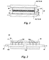
- FIG. 1 depicts an electronic device package with upper and lower heatsinks
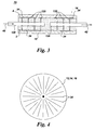
- FIG. 2 is a cross-sectional view of a single sided heat sink, with the radial millichannels formed in the upper lid;
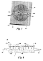
- FIG. 3 is a cross-sectional view of a double sided heat sink, with the radial millichannels formed in the lower and upper lids;
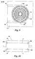
- FIG. 4 illustrates a heatsink design, which increases the number of radial channels
- FIG. 5 is a top view of a heat sink body with C-shaped manifolds and wedge-shaped inlet and outlet chambers;
- FIG. 6 is an inverse model of a double-sided heat sink with C-shaped manifolds and with radial channels formed in the lids;
- FIG. 7 is a perspective view of a heat sink body with C-shaped manifolds
- FIG. 8 is a cross-sectional view of a single-sided heat sink, with the radial millichannels formed in the body;
- FIG. 9 is a top view of a heat sink body with C-shaped manifolds and wedge-shaped inlet and outlet chambers and with radial millichannels formed in the body;
- FIG. 10 illustrates a heatsink configuration that does not include lids
- FIG. 11 illustrates a sealing arrangement for the double-sided heatsink of FIG. 13 ;
- FIG. 12 is a top view of a heat sink body with C-shaped manifolds and wedge-shaped inlet and outlet chambers arranged linearly relative to the respective inlet and outlet plena;
- FIG. 13 illustrates a double-sided heat sink configuration that does not include lids
- FIG. 14 illustrates a single-sided heat sink configuration that does not include lids
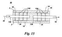
- FIG. 15 is a cross-sectional view of a double-sided heat sink, with the radial millichannels formed in the body.
- a heat sink 60, 70 for cooling at least one electronic device package 20 is described with reference to FIGS. 1-9 and 15 .
- an exemplary electronic device package 20 has an upper contact surface 22 and a lower contact surface 24.
- the heat sink 60, 70 comprises a lower lid 12, an upper lid 14 and a body 16 formed of at least one thermally conductive material.
- the thermally conductive material is selected from the group consisting of copper, aluminum, nickel, molybdenum, titanium, copper alloys, nickel alloys, molybdenum alloys, titanium alloys, aluminum silicon carbide (AlSiC), aluminum graphite and silicon nitride ceramic.
- the lower and upper lids 12, 14 and body 16 are formed of the same thermally conductive material(s). However, for other arrangements, different materials may be used.
- the body 16 is disposed between and sealed to the lower and upper lids 12, 14.
- the lids 12, 14 may be welded, brazed or diffusion bonded to the body 16, and conventional welding, brazing or diffusion bonding techniques may be employed.
- the body 16 defines a tapered inlet distribution chamber 136 configured to receive a coolant.
- the coolant include de-ionized water and other non-electrically conductive liquids.
- the coolant may comprise an electrically conductive liquid. As shown, for example, in FIG.
- the body 16 further defines a number of C-shaped inlet manifolds 130 configured to receive the coolant from the tapered inlet distribution chamber 136 and a number of inverted C-shaped outlet manifolds 132 configured to exhaust the coolant.
- the C-shaped inlet and inverted C-shaped outlet manifolds 130, 132 are interleaved (interdigitated) and are disposed in a circular arrangement, also referred to herein as axial.
- the phrases "circular arrangement” and "axial arrangement” should be understood to encompass both curved and straight "circular" passages connecting the radial passages. As shown, for example, in FIG.
- the inverted C-shaped outlet manifolds 132 extend around only a portion of the body 16 and terminate adjacent to opposing sides 135, 137 of the tapered inlet chamber 136.
- the body 16 further defines a tapered outlet chamber 138 configured to receive the coolant from the inverted C-shaped outlet manifolds 132.
- the C-shaped inlet manifolds 130 extend around only a portion of the body 16 and terminate adjacent to opposing sides 131, 133 of the tapered outlet chamber 138.
- the tapered inlet chamber 136 and the tapered outlet chamber 138 are wedge-shaped.
- the tapered inlet and outlet chambers 136, 138 may have other shapes as well.
- a number of millichannels 34 are formed in the body 16 and/or are formed in at least one of the lower and upper lids 12, 14 and are configured to receive the coolant from the C-shaped inlet manifolds 130 and to deliver the coolant to the inverted C-shaped outlet manifolds 132.
- the millichannels 34 may be formed in both the body 16 and in one or both of the lids 12, 14, in order to maximize the number of radial channels leading to a further reduction in pressure drop.
- the millichannels 34 are disposed in a radial arrangement.
- the millichannels 34 and the C-shaped inlet and inverted C-shaped outlet manifolds 132, 134 are further configured to cool one of the upper and lower contact surfaces 22, 24 of the electronic device package 20, as schematically indicated in FIG. 1 .
- the manifolds and millichannels are machined or cast into the base material.
- the body 16 and lids 12, 14 can be cast and/or machined.
- the pieces 12, 14, 16 can be cast and then machined to further define fine features and surface requirements.
- the flow passages are hermetically sealed by the lids 12, 14.
- the lids and having the heat sink hermetically sealed allows for cooling channels to extend beyond the pole face of the device that is being cooled. This allows for heat spreading effects to be utilized and helps to prevent coolant leakage during disassembly and service.
- the C-shaped manifolds 130, 132 have relatively larger cross-sectional areas than the millichannels 34.
- the width of the millichannels was in a range of about 0.5 mm to about 2.0 mm, and the depth of the millichannels was in a range of about 0.5 mm to about 2 mm.
- the cross-sectional areas of the channels may be determined to ensure pressure uniformity on the semiconductor. By making the pressure distribution on the semiconductor more uniform, the performance of the semiconductor is not compromised.
- millichannels 34 and C-shaped manifolds 130, 132 could have a variety of cross-sectional shapes, including but not limited to, rounded, circular, trapezoidal, triangular, and square/rectangular cross sections.
- the passage shape is selected based on the application and manufacturing constraints and affects the applicable manufacturing methods, as well as coolant flow.
- the incorporation of millichannels 34 into the heat sink 60, 70 significantly increases the surface area of heat conduction from the semiconductor device 20 to the coolant.
- At least one of the C-shaped inlet and inverted C-shaped outlet manifolds 130, 132 may have a variable depth.
- the depth of the C-shaped inlet manifolds 130 may have a maximum value at the tapered inlet chamber 136 and a minimum value at the sides 131, 133 of the tapered outlet chamber 138.
- the depth of the inverted C-shaped outlet manifolds 132 may have a minimum value at the sides 135, 137 of the tapered inlet chamber 136 and a maximum value at the tapered outlet chamber 138.
- this tapered arrangement achieves a more uniform flow distribution through the cooling circuit.
- FIG. 4 illustrates a design to increase the number of radial channels to facilitate a reduction in pressure drop with a corresponding improvement in cooling efficiency. More particularly, for the example arrangement shown in FIG. 6 , the number of radial millichannels 34 is larger near the circumference of the body 16 relative to the number of radial millichannels 34 near the center of the body 16. This arrangement permits the inclusion of additional radial channels for given spatial and machining constraints.
- the heat sink 60, 70 is configured for cooling a number of electronic device packages 20.
- FIG. 6 illustrates an example double-sided heat sink 70 configuration where the millichannels 34 are formed in the lids 12, 14.
- FIG. 15 illustrates an example double-sided heat sink 60, where the millichannels 34 are formed in the body.
- the millichannels 34 are formed in the body 16.
- a first subset of the C-shaped inlet manifolds and inverted C-shaped outlet manifolds 130, 132 and the millichannels 34 are formed in the first surface 2 of the body 16, and a second subset of the inlet manifolds and outlet manifolds 130, 132 and the millichannels 34 are formed in the second surface 4 of the body 16, as schematically indicated in FIG. 15 .
- the first subset of the inlet and outlet manifolds 130, 132 and the millichannels 34 is configured to cool an upper contact surface 22 of one of the electronic device packages 20 with the coolant
- the second subset of inlet and outlet manifolds 130, 132 and the millichannels 34 is configured to cool a lower contact surface 24 of another of the electronic device packages 20 with the coolant, as schematically depicted in FIG. 1 .
- FIG. 1 is merely illustrative, and any number of electronic device packages 20 and corresponding heat sinks 60, 70 for cooling the electronic device packages may be incorporated into a given stack, depending on the specific application.
- One of the many benefits of the present invention is its flexibility and modularity for cooling a desired number of device packages.
- the millichannels 34 are formed in each of the lower and upper lids 12, 14.
- a second subset of the C-shaped inlet manifolds and inverted C-shaped outlet manifolds 130, 132 is formed in the second surface 4 of the body 16 (see FIG. 7 ) and a second subset of the millichannels 34 is formed in the upper lid 14 (see FIG. 6 ).
- a first subset of the inlet and outlet manifolds 130, 132 is formed in the first surface 2 of the body 16, and, as indicated in FIG.
- a first subset of the millichannels 34 is formed in the lower lid 12.
- the first subsets of the inlet and outlet manifolds 130, 132 and the millichannels 34 are configured to cool an upper contact surface 22 of one of the electronic device packages 20 with the coolant
- the second subsets of inlet and outlet manifolds 130, 132 and the millichannels 34 are configured to cool a lower contact surface 24 of another of the electronic device packages 20 with the coolant.
- the body 16 further defines an inlet plenum 40 configured to supply the coolant to the tapered inlet distribution chamber 136, where the tapered inlet chamber 136 and the inlet plenum 40 are arranged linearly.
- the body 16 further defines an outlet plenum 42 configured to receive the coolant from the tapered outlet chamber 138, where the tapered outlet chamber 138 and the outlet plenum 42 are arranged linearly.
- the term "linearly” should be understood to encompass orientations of the chambers 136, 138 relative to the respective plenum 40, 42 that are within plus or minus ten degrees (+/-10°) of one another.
- FIGS. 5 and 6 illustrate a perpendicular configuration for the chambers and the respective plena.
- the body 16 further defines an inlet plenum 40 configured to supply the coolant to the tapered inlet chamber 136, where the tapered inlet distribution chamber 136 and the inlet plenum 40 are arranged perpendicularly.
- the body 16 further defines an outlet plenum 42 configured to receive the coolant from the tapered outlet chamber 138, where the tapered outlet chamber 138 and the outlet plenum 42 are arranged perpendicularly.
- the term "perpendicularly” should be understood to encompass orientations of the tapered chambers 136, 138 relative to the respective plenum 40, 42 that are within (90° +/- 10°) of one another.
- the fluid connections are simplified. For example, this configuration may require four holes to be bored for the fluid delivery and removal, two of which are later plugged.
- the heat sinks 60, 70 can be single-sided or double-sided. One-sided heat sink configurations 60, 70 for cooling an electronic device package 20 are described with reference to FIGS. 2 and 8 .
- the heat sink 60, 70 comprises a lid 12, 14 formed of at least one thermally conductive material and a body 16 formed of at least one thermally conductive material. The body 16 is sealed to the lid 12, 14, and the construction of the lid and body is described above. As indicated, for example, in FIG.
- the body 16 defines a tapered inlet distribution chamber 136 configured to receive a coolant, a number of C-shaped inlet manifolds 130 configured to receive the coolant from the tapered inlet distribution chamber 136, and a number of inverted C-shaped outlet manifolds 132 configured to exhaust the coolant.
- the inlet and outlet manifolds 130, 132 are interleaved (interdigitated) and are disposed in a circular arrangement.
- the inverted C-shaped outlet manifolds 132 extend around only a portion of the body 16 and terminate adjacent to opposing sides 135, 137 of the tapered inlet chamber 136.
- FIG. 8 the inlet and outlet manifolds 130, 132 are interleaved (interdigitated) and are disposed in a circular arrangement.
- the inverted C-shaped outlet manifolds 132 extend around only a portion of the body 16 and terminate adjacent to opposing sides 135, 137 of the tapered inlet chamber 136.
- the body 16 further defines a tapered outlet chamber 138 configured to receive the coolant from the inverted C-shaped outlet manifolds 132.
- the C-shaped inlet manifolds 130 extend around only a portion of the body 16 and terminate adjacent to opposing sides 131, 133 of the tapered outlet chamber 138.
- millichannels 34 are formed in the body 16 ( FIG. 8 ) or in the lid 12, 14 ( FIG. 2 ) and are configured to receive the coolant from the C-shaped inlet manifolds 130 and to deliver the coolant to the inverted C-shaped outlet manifolds 132.
- the millichannels 34 may be formed in both the body 16 and in the lid 12, 14, in order to maximize the number of radial channels leading to a further reduction in pressure drop.
- the millichannels 34 are disposed in a radial arrangement, and the millichannels 34 and the inlet and outlet manifolds 132, 134 are further configured to cool one of the upper and lower contact surfaces 22, 24 of the electronic device package 20, as schematically depicted in FIG. 1 .
- the millichannels 34 are formed in the body 16. More particularly, the inlet and outlet manifolds 130, 132 and radial millichannels 34 are formed in only one of the first surface 2 or second surface 4 of the body 16 (on the second surface 4 for the case of FIG. 8 ), such that the heat sink 60 is a single-sided heat sink 60, as shown for example in FIG. 8 .
- the millichannels 34 are formed in the lid 14.
- placing radial channels in the lid reduces the thermal resistance by placing the coolant closer to the electronic device package 20.
- the inlet manifolds and outlet manifolds 130, 132 are formed in only one of the first surface 2 or second surface 4 of the body 16 (on the second surface 4 for the case of FIG. 2 ), such that the heat sink 70 is a single-sided heat sink 70, as shown for example in FIG. 2 .
- the cooling delivery/removal system is arranged such that machining on less sides is required. Holes are bored from one face to the midpoint of the material. Then, holes are bored down from the main surface to meet the other holes. Through a milling process, the wedge-shaped chambers (which may also be rectangular) are cut, which intersect with C-shaped and inverted C-shaped manifolds, which alternate as left-facing or right-facing, such that every other one connects to the inlet chamber and the rest to the outlet chamber. Then, radial millichannels may be cut into either the main body or the lids, and all pieces are attached through brazing, welding, or other methods, such as diffusion bonding.
- these implementations reduce the manufacturing costs by requiring manufacturing on only three surfaces (for cooling, an additional surface for electrical connections).
- the upper contact surface 22 and lower contact surface 24 can be circular in cross-section, and the body 16 can be cylindrical (i.e., a disk or hockey-puck arrangement).
- the body 16 can be cylindrical (i.e., a disk or hockey-puck arrangement).
- other geometries can be employed, including without limitation, square and rectangular cross-sections.
- the electronic device package 20 is a press-package 20.
- the invention is not limited to any specific device structure, the following example press-package configuration is provided for illustrative purposes.
- the press-package 20 comprises at least one semiconductor device 21 formed on a wafer 23, upper and lower coefficient of thermal-expansion (CTE) matched plates 25, 27, and upper and lower electrodes 28, 29.
- the wafer 23 is disposed between the CTE plates 25, 27, the upper electrode 28 is disposed above the upper CTE plate 25, and the lower CTE plate 27 is disposed above the lower electrode 29, as shown for example in FIG. 1 .
- each of the wafer 23, CTE plates 25, 27 and electrodes 28, 29 may have a circular cross-section.
- semiconductor devices include IGCTs, GTOs and IGBTs.
- the present invention finds application to semiconductor devices manufactured from a variety of semiconductors, non-limiting examples of which include silicon (Si), silicon carbide (SiC), gallium nitride (GaN), and gallium arsenide (GaAs).
- the press-package typically includes an insulating (for example, ceramic) housing 26, as indicated for example in FIG. 1 .
- FIG. 1 shows the heat sinks 60, 70 as extending outside the housing 26, in other embodiments, the bodies 16 of the heat sinks 60, 70 are disposed within the housing 26.
- electrodes 28, 29 can extend vertically beyond the bounds of housing 26, for example with a compliant seal disposed between the outer circumference of electrodes 28 (and 29) and the housing 26.
- the heat sinks 60, 70 can extend out of the housing (as shown) to enable electrical connections and for placing other devices that need to be cooled. Therefore, the body 16 can have a larger diameter than housing 26.
- the heat sinks 60, 70 prevent the coolant from leaking onto the electronics during assembly, disassembly, or servicing.
- the heat sinks 60, 70 provide high-performance cooling, in a uniform manner across the pole face of the electronic device package 20.
- a lidless configuration may be employed for direct cooling. Accordingly, another heat sink 80 configuration is described with reference to FIGS. 5 , 7 and 9-14 .
- a heat sink 80 is provided, for cooling at least one electronic device package 20. As indicated in FIG. 1 , the electronic device package has upper and lower contact surfaces 22, 24. As indicated, for example, in FIG. 10 , the heat sink 80 comprises a body 16 formed of at least one thermally conductive material. As shown in FIG.
- the body 16 defines a tapered inlet distribution chamber 136 configured to receive a coolant, C-shaped inlet manifolds 130 configured to receive the coolant from the tapered inlet distribution chamber 136, inverted C-shaped outlet manifolds 132 configured to exhaust the coolant.
- the inlet and outlet manifolds 130, 132 are interleaved (interdigitated) and are disposed in a circular (axial) arrangement.
- the inverted C-shaped outlet manifolds 132 extend around only a portion of the body 16 and terminate adjacent to opposing sides 135, 137 of the tapered inlet chamber 136. As shown in FIG.
- the body 16 further defines a tapered outlet chamber 138 configured to receive the coolant from the outlet manifolds 132.
- the C-shaped inlet manifolds 130 extend around only a portion of the body 16 and terminate adjacent to opposing sides 131, 133 of the tapered outlet chamber 138.
- the tapered inlet and outlet chambers 136, 138 are wedge-shaped.
- the tapered chambers 136, 138 may have other shapes.
- the body 16 further defines millichannels 34 configured to receive the coolant from the C-shaped inlet manifolds 130 and to deliver the coolant to the outlet manifolds 132.
- the millichannels 34 are disposed in a radial arrangement, and the millichannels 34 and the inlet and outlet manifolds 132, 134 are further configured to directly cool one of the upper and lower contact surfaces 22, 24 of the electronic device package 20, as schematically indicated in FIG. 1 .
- Example dimensions and cross-sections for the manifolds 130, 132 and millichannels 34 are presented above.
- at least one of the inlet and outlet manifolds 130, 132 may have a variable depth. Beneficially, such a tapered arrangement achieves a more uniform flow distribution through the cooling circuit.
- the number of radial millichannels 34 is larger near the circumference of the body 16 relative to the number of radial millichannels 34 near the center of the body 16.
- the arrangement shown in FIG. 4 provides enhanced cooling by permitting the inclusion of additional radial channels for given spatial and machining constraints. Although this arrangement is not expressly shown for the lidless configuration of FIGS. 10 and 11 , it is shown for the case of C-shaped manifolds in FIG. 6 .
- the body 16 further defines a groove 302 for receiving a gasket 304.
- the gasket 304 comprises an O-ring.
- this assembly process is relatively simple and robust, requiring few manufacturing steps and eliminating the need for more complex assembly techniques, such as soldering or other metal bonding techniques.
- the body 16 further defines an inlet plenum 40 configured to supply the coolant to the tapered inlet distribution chamber 136 and an outlet plenum 42 configured to receive the coolant from the tapered outlet chamber 138.
- the tapered inlet chamber 136 and the inlet plenum 40 may be arranged linearly, and the tapered outlet chamber 138 and the outlet plenum 42 may be arranged linearly, as shown, for example in FIG.12 .
- the tapered inlet chamber 136 and the inlet plenum 40 may be arranged perpendicularly, and the tapered outlet chamber 138 and the outlet plenum 42 may be arranged perpendicularly, as shown in FIG. 9 .
- the heat sink 80 is configured for cooling a number of electronic device packages 20.
- FIGS. 10 and 13 schematically illustrate an example double-sided heat sink 80 configuration.
- a first subset of inlet and outlet manifolds 130, 132 and the millichannels 34 are formed in the first surface 2 of the body 16, and a second subset of inlet and outlet manifolds 130, 132 and millichannels 34 are formed in the second surface 4 of the body 16, as indicated in FIG. 13 .
- the first subset of the manifolds 130, 132 and millichannels 34 is configured to directly cool an upper contact surface 22 ( FIG.
- the second subset of manifolds 130, 132 and millichannels 34 is configured to directly cool a lower contact surface 24 ( FIG. 1 ) of another of the electronic device packages 20 with the coolant, as indicated in FIG. 13 .
- the heat sink 80 is configured as a single sided heat sink.
- the inlet and outlet manifolds 130, 132 are formed in only one of the first surface 2 or second surface 4 of the body 16 (on the second surface 4 for the case of FIG. 14 ), such that the heat sink 80 is a single-sided heat sink 80.
- heat sink 80 provides enhanced heat transfer relative to conventional cooling of power devices, with a robust and simple sealing arrangement.
- the heat sinks 80 can be sealed to adjacent device packages 20 using relatively simple O-ring assemblies.
- Heat sink 80 is integral to the press-package, directly cooling the power devices with direct contact by the coolant, thereby enhancing the heat transfer.
- heat sink 80 reduces the risk of leaking or fatigue failure and cost by reducing the number of brazes (or other means of mechanical attachment) required to contain the coolant.
- the interleaved C-shaped inlet and outlet channels deliver coolant uniformly to the surface of the device being cooled, and the millichannels increase the surface area of heat conduction from the power device to the coolant in this integral heat sink.
- the heat sinks 60, 70, 80 are particularly desirable for applications demanding very high reliability, such as oil and gas liquefied natural gas (LNG) and pipeline drives, oil and gas sub-sea transmission and distribution, and drives.
- LNG oil and gas liquefied natural gas
- the heat sinks 60, 70, 80 can be employed in a variety of applications, non-limiting examples of which include high power applications, such as metal rolling mills, paper mills and traction.
Landscapes
- Cooling Or The Like Of Semiconductors Or Solid State Devices (AREA)
- Cooling Or The Like Of Electrical Apparatus (AREA)
Abstract
Description
- The invention relates generally to power electronics and, more particularly, to advanced cooling for power electronics.
- High power converters, such as medium voltage industrial drives, frequency converters for oil and gas, traction drives, Flexible AC Transmission (FACT) devices, and other high power conversion equipment, for example rectifiers and inverters, typically include press-pack power devices with liquid cooling. Non-limiting examples of power devices include integrated gate commutated thyristors (IGCTs), diodes, insulated gate bipolar transistors (IGBTs), thyristors and gate turn-off thyristors (GTOs). Press-pack devices are particularly advantageous in high power applications, and benefits of press-packs include double-sided cooling, as well as the absence of a plasma explosion event during failure.
- To construct a high power converter circuit using press-pack devices, heat sinks and press-pack devices are typically sandwiched to form a stack. State-of-the-art power converter stacks typically employ conventional liquid cooled heat sinks with larger diameter cooling channels. In certain applications, thermal grease layers are disposed between respective ones of the press-pack device and the conventional liquid cooled heat sink. In other applications, at least some of the layers are simply held together by pressure, with no thermal grease in between them. This arrangement results in significant thermal contact resistance.
- It would be desirable to provide improved heat sink designs which prevent the coolant from leaking onto the electronics during assembly, disassembly, or servicing. It would further be desirable to provide improved heat sink designs that enable the use of heat spreading effects for enhanced cooling of power electronics. In addition, improved heat sink designs with lower manufacturing costs and enhanced heat transfer are also desired.
- One aspect of the present invention resides in a heat sink for cooling at least one electronic device package. The electronic device package has an upper contact surface and a lower contact surface. The heat sink includes a lower lid, an upper lid, and a body formed of at least one thermally conductive material. The body is disposed between and sealed to the lower and upper lids and defines a tapered inlet distribution chamber configured to receive a coolant, a number of C-shaped inlet manifolds configured to receive the coolant from the tapered inlet distribution chamber, and a number of inverted C-shaped outlet manifolds configured to exhaust the coolant. The C-shaped inlet and inverted C-shaped outlet manifolds are interleaved and are disposed in a circular arrangement, and the inverted C-shaped outlet manifolds extend around only a portion of the body and terminate adjacent to opposing sides of the tapered inlet chamber. The body further defines a tapered outlet chamber configured to receive the coolant from the inverted C-shaped outlet manifolds. The C-shaped inlet manifolds extend around only a portion of the body and terminate adjacent to opposing sides of the tapered outlet chamber. Millichannels are formed in the body or are formed in at least one of the lower and upper lids and are configured to receive the coolant from the C-shaped inlet manifolds and to deliver the coolant to the inverted C-shaped outlet manifolds. The millichannels are disposed in a radial arrangement, and the millichannels and the C-shaped inlet and inverted C-shaped outlet manifolds are further configured to cool one of the upper and lower contact surfaces of the electronic device package.
- Another aspect of the invention resides in a heat sink for cooling an electronic device package. The heat sink includes a lid and a body formed of at least one thermally conductive material. The body is sealed to the lid and defines a tapered inlet distribution chamber configured to receive a coolant, a number of C-shaped inlet manifolds configured to receive the coolant from the tapered inlet distribution chamber, and a number of inverted C-shaped outlet manifolds configured to exhaust the coolant. The C-shaped inlet and inverted C-shaped outlet manifolds are interleaved and are disposed in a circular arrangement. The inverted C-shaped outlet manifolds extend around only a portion of the body and terminate adjacent to opposing sides of the tapered inlet chamber. The body further defines a tapered outlet chamber configured to receive the coolant from the inverted C-shaped outlet manifolds. The C-shaped inlet manifolds extend around only a portion of the body and terminate adjacent to opposing sides of the tapered outlet chamber. Millichannels are formed in the body or in the lid and are configured to receive the coolant from the C-shaped inlet manifolds and to deliver the coolant to the inverted C-shaped outlet manifolds. The millichannels are disposed in a radial arrangement, and the millichannels and the C-shaped inlet and outlet manifolds are further configured to cool one of the upper or lower contact surfaces of the electronic device package.
- Yet another aspect of the invention resides in a heat sink for directly cooling at least one electronic device package. The heat sink includes a body formed of at least one thermally conductive material, where the body defines a tapered inlet distribution chamber configured to receive a coolant, a number of C-shaped inlet manifolds configured to receive the coolant from the tapered inlet distribution chamber, and a number of inverted C-shaped outlet manifolds configured to exhaust the coolant. The C-shaped inlet and inverted C-shaped outlet manifolds are interleaved and are disposed in a circular arrangement. The inverted C-shaped outlet manifolds extend around only a portion of the body and terminate adjacent to opposing sides of the tapered inlet chamber. The body further defines a tapered outlet chamber configured to receive the coolant from the inverted C-shaped outlet manifolds. The C-shaped inlet manifolds extend around only a portion of the body and terminate adjacent to opposing sides of the tapered outlet chamber. The body further defines a number of millichannels configured to receive the coolant from the C-shaped inlet manifolds and to deliver the coolant to the inverted C-shaped outlet manifolds. The millichannels are disposed in a radial arrangement, and the millichannels and the C-shaped inlet and inverted C-shaped outlet manifolds are further configured to directly cool one of the upper and lower contact surfaces of the electronic device package.
- These and other features, aspects, and advantages of the present invention will become better understood when the following detailed description is read with reference to the accompanying drawings in which like characters represent like parts throughout the drawings, wherein:
-
FIG. 1 depicts an electronic device package with upper and lower heatsinks; -
FIG. 2 is a cross-sectional view of a single sided heat sink, with the radial millichannels formed in the upper lid; -
FIG. 3 is a cross-sectional view of a double sided heat sink, with the radial millichannels formed in the lower and upper lids; -
FIG. 4 illustrates a heatsink design, which increases the number of radial channels; -
FIG. 5 is a top view of a heat sink body with C-shaped manifolds and wedge-shaped inlet and outlet chambers; -
FIG. 6 is an inverse model of a double-sided heat sink with C-shaped manifolds and with radial channels formed in the lids; -
FIG. 7 is a perspective view of a heat sink body with C-shaped manifolds; -
FIG. 8 is a cross-sectional view of a single-sided heat sink, with the radial millichannels formed in the body; -
FIG. 9 is a top view of a heat sink body with C-shaped manifolds and wedge-shaped inlet and outlet chambers and with radial millichannels formed in the body; -
FIG. 10 illustrates a heatsink configuration that does not include lids; -
FIG. 11 illustrates a sealing arrangement for the double-sided heatsink ofFIG. 13 ; -
FIG. 12 is a top view of a heat sink body with C-shaped manifolds and wedge-shaped inlet and outlet chambers arranged linearly relative to the respective inlet and outlet plena; -
FIG. 13 illustrates a double-sided heat sink configuration that does not include lids; -
FIG. 14 illustrates a single-sided heat sink configuration that does not include lids; and -
FIG. 15 is a cross-sectional view of a double-sided heat sink, with the radial millichannels formed in the body. - A
heat sink electronic device package 20 is described with reference toFIGS. 1-9 and15 . As indicated, for example inFIG. 1 , an exemplaryelectronic device package 20 has anupper contact surface 22 and alower contact surface 24. For the example arrangements shown inFIGS. 3 and6 , theheat sink lower lid 12, anupper lid 14 and abody 16 formed of at least one thermally conductive material. The thermally conductive material is selected from the group consisting of copper, aluminum, nickel, molybdenum, titanium, copper alloys, nickel alloys, molybdenum alloys, titanium alloys, aluminum silicon carbide (AlSiC), aluminum graphite and silicon nitride ceramic. For particular configurations, the lower andupper lids body 16 are formed of the same thermally conductive material(s). However, for other arrangements, different materials may be used. - For the configurations shown in
FIGS. 3 and6 , thebody 16 is disposed between and sealed to the lower andupper lids lids body 16, and conventional welding, brazing or diffusion bonding techniques may be employed. As shown, for example, inFIG. 7 , thebody 16 defines a taperedinlet distribution chamber 136 configured to receive a coolant. Non-limiting examples of the coolant include de-ionized water and other non-electrically conductive liquids. In addition, for certain applications, the coolant may comprise an electrically conductive liquid. As shown, for example, inFIG. 7 , thebody 16 further defines a number of C-shapedinlet manifolds 130 configured to receive the coolant from the taperedinlet distribution chamber 136 and a number of inverted C-shaped outlet manifolds 132 configured to exhaust the coolant. The C-shaped inlet and inverted C-shaped outlet manifolds 130, 132 are interleaved (interdigitated) and are disposed in a circular arrangement, also referred to herein as axial. As used herein, the phrases "circular arrangement" and "axial arrangement" should be understood to encompass both curved and straight "circular" passages connecting the radial passages. As shown, for example, inFIG. 5 , the inverted C-shaped outlet manifolds 132 extend around only a portion of thebody 16 and terminate adjacent to opposingsides inlet chamber 136. As shown, for example, inFIG. 7 , thebody 16 further defines a taperedoutlet chamber 138 configured to receive the coolant from the inverted C-shaped outlet manifolds 132. As shown, for example, inFIG. 5 , the C-shapedinlet manifolds 130 extend around only a portion of thebody 16 and terminate adjacent to opposingsides outlet chamber 138. - For the example configurations shown in
FIGS. 6 ,7 , and9 , the taperedinlet chamber 136 and the taperedoutlet chamber 138 are wedge-shaped. However, the tapered inlet andoutlet chambers - Depending on the specific configuration, a number of
millichannels 34 are formed in thebody 16 and/or are formed in at least one of the lower andupper lids inlet manifolds 130 and to deliver the coolant to the inverted C-shaped outlet manifolds 132. Although not expressly illustrated, themillichannels 34 may be formed in both thebody 16 and in one or both of thelids FIGS. 4 ,6 and9 , themillichannels 34 are disposed in a radial arrangement. Themillichannels 34 and the C-shaped inlet and inverted C-shaped outlet manifolds 132, 134 are further configured to cool one of the upper and lower contact surfaces 22, 24 of theelectronic device package 20, as schematically indicated inFIG. 1 . - These internal flow structures take coolant from the
inlet chamber 136 and distribute it across the entire cooled surface for uniform thermal performance. The coolant passes through the C-shapedmanifolds 130, then through the radial millichannels 34 to the set of inverted C-shapedmanifolds 132, and back throughradial millichannels 34 to theoutlet chamber 138. The manifolds and millichannels are machined or cast into the base material. Thebody 16 andlids pieces lids - For particular embodiments, the C-shaped
manifolds millichannels 34. In one non-limiting example, the width of the millichannels was in a range of about 0.5 mm to about 2.0 mm, and the depth of the millichannels was in a range of about 0.5 mm to about 2 mm. In particular, the cross-sectional areas of the channels may be determined to ensure pressure uniformity on the semiconductor. By making the pressure distribution on the semiconductor more uniform, the performance of the semiconductor is not compromised. - Further, it should be noted that the millichannels 34 and C-shaped
manifolds millichannels 34 into theheat sink semiconductor device 20 to the coolant. - In addition, for particular arrangements, at least one of the C-shaped inlet and inverted C-shaped outlet manifolds 130, 132 may have a variable depth. For example, the depth of the C-shaped
inlet manifolds 130 may have a maximum value at the taperedinlet chamber 136 and a minimum value at thesides outlet chamber 138. Similarly, the depth of the inverted C-shaped outlet manifolds 132 may have a minimum value at thesides inlet chamber 136 and a maximum value at the taperedoutlet chamber 138. Beneficially, this tapered arrangement achieves a more uniform flow distribution through the cooling circuit. -
FIG. 4 illustrates a design to increase the number of radial channels to facilitate a reduction in pressure drop with a corresponding improvement in cooling efficiency. More particularly, for the example arrangement shown inFIG. 6 , the number ofradial millichannels 34 is larger near the circumference of thebody 16 relative to the number ofradial millichannels 34 near the center of thebody 16. This arrangement permits the inclusion of additional radial channels for given spatial and machining constraints. - For particular configurations, the
heat sink FIG. 6 illustrates an example double-sided heat sink 70 configuration where themillichannels 34 are formed in thelids FIG. 15 illustrates an example double-sided heat sink 60, where themillichannels 34 are formed in the body. For the example configurations illustrated inFIGS. 8 and15 , themillichannels 34 are formed in thebody 16. For the arrangement ofFIG. 15 , a first subset of the C-shaped inlet manifolds and inverted C-shaped outlet manifolds 130, 132 and themillichannels 34 are formed in thefirst surface 2 of thebody 16, and a second subset of the inlet manifolds and outlet manifolds 130, 132 and themillichannels 34 are formed in thesecond surface 4 of thebody 16, as schematically indicated inFIG. 15 . The first subset of the inlet and outlet manifolds 130, 132 and themillichannels 34 is configured to cool anupper contact surface 22 of one of the electronic device packages 20 with the coolant, and the second subset of inlet and outlet manifolds 130, 132 and themillichannels 34 is configured to cool alower contact surface 24 of another of the electronic device packages 20 with the coolant, as schematically depicted inFIG. 1 . - It should be noted that the specific arrangement shown in
FIG. 1 is merely illustrative, and any number of electronic device packages 20 andcorresponding heat sinks - Similarly, for the double-
sided heat sink 70 configuration shown inFIGS. 3 and6 , themillichannels 34 are formed in each of the lower andupper lids FIGS. 6 and7 , a second subset of the C-shaped inlet manifolds and inverted C-shaped outlet manifolds 130, 132 is formed in thesecond surface 4 of the body 16 (seeFIG. 7 ) and a second subset of themillichannels 34 is formed in the upper lid 14 (seeFIG. 6 ). Similar to the arrangement shown inFIG. 7 , a first subset of the inlet and outlet manifolds 130, 132 is formed in thefirst surface 2 of thebody 16, and, as indicated inFIG. 6 , a first subset of themillichannels 34 is formed in thelower lid 12. As schematically indicated inFIG. 1 , the first subsets of the inlet and outlet manifolds 130, 132 and themillichannels 34 are configured to cool anupper contact surface 22 of one of the electronic device packages 20 with the coolant, and the second subsets of inlet and outlet manifolds 130, 132 and themillichannels 34 are configured to cool alower contact surface 24 of another of the electronic device packages 20 with the coolant. - For the arrangement depicted in
FIG. 12 , thebody 16 further defines aninlet plenum 40 configured to supply the coolant to the taperedinlet distribution chamber 136, where the taperedinlet chamber 136 and theinlet plenum 40 are arranged linearly. Thebody 16 further defines anoutlet plenum 42 configured to receive the coolant from the taperedoutlet chamber 138, where the taperedoutlet chamber 138 and theoutlet plenum 42 are arranged linearly. As used here, the term "linearly" should be understood to encompass orientations of thechambers respective plenum - The invention is not limited to a specific relative orientation of the inlet and
outlet chambers FIGS. 5 and 6 illustrate a perpendicular configuration for the chambers and the respective plena. For the example configurations shown inFIGS. 5 and 6 , thebody 16 further defines aninlet plenum 40 configured to supply the coolant to the taperedinlet chamber 136, where the taperedinlet distribution chamber 136 and theinlet plenum 40 are arranged perpendicularly. Thebody 16 further defines anoutlet plenum 42 configured to receive the coolant from the taperedoutlet chamber 138, where the taperedoutlet chamber 138 and theoutlet plenum 42 are arranged perpendicularly. As used here, the term "perpendicularly" should be understood to encompass orientations of the taperedchambers respective plenum coolant inlet plenum 40 andoutlet plenum 42 in the same face, the fluid connections are simplified. For example, this configuration may require four holes to be bored for the fluid delivery and removal, two of which are later plugged. - The heat sinks 60, 70 can be single-sided or double-sided. One-sided
heat sink configurations electronic device package 20 are described with reference toFIGS. 2 and8 . Theheat sink lid body 16 formed of at least one thermally conductive material. Thebody 16 is sealed to thelid FIG. 7 , thebody 16 defines a taperedinlet distribution chamber 136 configured to receive a coolant, a number of C-shapedinlet manifolds 130 configured to receive the coolant from the taperedinlet distribution chamber 136, and a number of inverted C-shaped outlet manifolds 132 configured to exhaust the coolant. As shown, for example, inFIG. 8 , the inlet and outlet manifolds 130, 132 are interleaved (interdigitated) and are disposed in a circular arrangement. As indicated inFIG. 5 , the inverted C-shaped outlet manifolds 132 extend around only a portion of thebody 16 and terminate adjacent to opposingsides inlet chamber 136. As indicated, for example, inFIG. 7 , thebody 16 further defines a taperedoutlet chamber 138 configured to receive the coolant from the inverted C-shaped outlet manifolds 132. As indicated inFIG. 5 , the C-shapedinlet manifolds 130 extend around only a portion of thebody 16 and terminate adjacent to opposingsides outlet chamber 138. For the single-sided arrangements illustrated inFIGS. 2 and8 , millichannels 34 are formed in the body 16 (FIG. 8 ) or in thelid 12, 14 (FIG. 2 ) and are configured to receive the coolant from the C-shapedinlet manifolds 130 and to deliver the coolant to the inverted C-shaped outlet manifolds 132. In addition, although not expressly illustrated, themillichannels 34 may be formed in both thebody 16 and in thelid electronic device package 20, as schematically depicted inFIG. 1 . - For the example configuration shown in
FIG. 9 , themillichannels 34 are formed in thebody 16. More particularly, the inlet and outlet manifolds 130, 132 andradial millichannels 34 are formed in only one of thefirst surface 2 orsecond surface 4 of the body 16 (on thesecond surface 4 for the case ofFIG. 8 ), such that theheat sink 60 is a single-sided heat sink 60, as shown for example inFIG. 8 . - For the example configuration shown in
FIG. 2 , themillichannels 34 are formed in thelid 14. Beneficially, placing radial channels in the lid reduces the thermal resistance by placing the coolant closer to theelectronic device package 20. More particularly, the inlet manifolds and outlet manifolds 130, 132 are formed in only one of thefirst surface 2 orsecond surface 4 of the body 16 (on thesecond surface 4 for the case ofFIG. 2 ), such that theheat sink 70 is a single-sided heat sink 70, as shown for example inFIG. 2 . - Beneficially, for these arrangements, the cooling delivery/removal system is arranged such that machining on less sides is required. Holes are bored from one face to the midpoint of the material. Then, holes are bored down from the main surface to meet the other holes. Through a milling process, the wedge-shaped chambers (which may also be rectangular) are cut, which intersect with C-shaped and inverted C-shaped manifolds, which alternate as left-facing or right-facing, such that every other one connects to the inlet chamber and the rest to the outlet chamber. Then, radial millichannels may be cut into either the main body or the lids, and all pieces are attached through brazing, welding, or other methods, such as diffusion bonding. Thus, these implementations reduce the manufacturing costs by requiring manufacturing on only three surfaces (for cooling, an additional surface for electrical connections).
- For the exemplary embodiments described above with reference to
FIGS. 1-9 and15 , theupper contact surface 22 andlower contact surface 24 can be circular in cross-section, and thebody 16 can be cylindrical (i.e., a disk or hockey-puck arrangement). However, other geometries can be employed, including without limitation, square and rectangular cross-sections. For the example arrangement depicted inFIG. 1 , theelectronic device package 20 is a press-package 20. Although the invention is not limited to any specific device structure, the following example press-package configuration is provided for illustrative purposes. In the example, the press-package 20 comprises at least onesemiconductor device 21 formed on a wafer 23, upper and lower coefficient of thermal-expansion (CTE) matchedplates lower electrodes CTE plates upper electrode 28 is disposed above theupper CTE plate 25, and thelower CTE plate 27 is disposed above thelower electrode 29, as shown for example inFIG. 1 . For the press-package embodiment, each of the wafer 23,CTE plates electrodes housing 26, as indicated for example inFIG. 1 . AlthoughFIG. 1 shows the heat sinks 60, 70 as extending outside thehousing 26, in other embodiments, thebodies 16 of the heat sinks 60, 70 are disposed within thehousing 26. Moreover,electrodes housing 26, for example with a compliant seal disposed between the outer circumference of electrodes 28 (and 29) and thehousing 26. In addition, the heat sinks 60, 70 can extend out of the housing (as shown) to enable electrical connections and for placing other devices that need to be cooled. Therefore, thebody 16 can have a larger diameter thanhousing 26. - Beneficially, by forming a hermetic seal, the heat sinks 60, 70 prevent the coolant from leaking onto the electronics during assembly, disassembly, or servicing. In addition, the heat sinks 60, 70 provide high-performance cooling, in a uniform manner across the pole face of the
electronic device package 20. - In addition to the configurations described above, a lidless configuration may be employed for direct cooling. Accordingly, another
heat sink 80 configuration is described with reference toFIGS. 5 ,7 and9-14 . As shown for example, inFIG. 1 , aheat sink 80 is provided, for cooling at least oneelectronic device package 20. As indicated inFIG. 1 , the electronic device package has upper and lower contact surfaces 22, 24. As indicated, for example, inFIG. 10 , theheat sink 80 comprises abody 16 formed of at least one thermally conductive material. As shown inFIG. 7 , thebody 16 defines a taperedinlet distribution chamber 136 configured to receive a coolant, C-shapedinlet manifolds 130 configured to receive the coolant from the taperedinlet distribution chamber 136, inverted C-shaped outlet manifolds 132 configured to exhaust the coolant. As shown, for example, inFIG. 5 , the inlet and outlet manifolds 130, 132 are interleaved (interdigitated) and are disposed in a circular (axial) arrangement. As also indicated inFIG. 6 , the inverted C-shaped outlet manifolds 132 extend around only a portion of thebody 16 and terminate adjacent to opposingsides inlet chamber 136. As shown inFIG. 7 , thebody 16 further defines a taperedoutlet chamber 138 configured to receive the coolant from the outlet manifolds 132. As shown, for example, inFIG. 5 , the C-shapedinlet manifolds 130 extend around only a portion of thebody 16 and terminate adjacent to opposingsides outlet chamber 138. For the illustrated examples, the tapered inlet andoutlet chambers tapered chambers - As indicated, for example, in
FIGS. 9 and11 , thebody 16 further defines millichannels 34 configured to receive the coolant from the C-shapedinlet manifolds 130 and to deliver the coolant to the outlet manifolds 132. The millichannels 34 are disposed in a radial arrangement, and the millichannels 34 and the inlet and outlet manifolds 132, 134 are further configured to directly cool one of the upper and lower contact surfaces 22, 24 of theelectronic device package 20, as schematically indicated inFIG. 1 . Example dimensions and cross-sections for themanifolds - Beneficially, by incorporating the millichannels and inlet/outlet manifolds into the
body 16, the assembly process is simplified. In particular, this single-piece configuration eliminates the need to bond two components. - For the example configuration shown in
FIG. 4 , the number ofradial millichannels 34 is larger near the circumference of thebody 16 relative to the number ofradial millichannels 34 near the center of thebody 16. As noted above, the arrangement shown inFIG. 4 provides enhanced cooling by permitting the inclusion of additional radial channels for given spatial and machining constraints. Although this arrangement is not expressly shown for the lidless configuration ofFIGS. 10 and11 , it is shown for the case of C-shaped manifolds inFIG. 6 . - For the example arrangement shown in
FIGS. 10 and11 , thebody 16 further defines agroove 302 for receiving agasket 304. For particular arrangements, thegasket 304 comprises an O-ring. Beneficially, this assembly process is relatively simple and robust, requiring few manufacturing steps and eliminating the need for more complex assembly techniques, such as soldering or other metal bonding techniques. - For the example arrangement shown in
FIG. 12 , thebody 16 further defines aninlet plenum 40 configured to supply the coolant to the taperedinlet distribution chamber 136 and anoutlet plenum 42 configured to receive the coolant from the taperedoutlet chamber 138. The taperedinlet chamber 136 and theinlet plenum 40 may be arranged linearly, and the taperedoutlet chamber 138 and theoutlet plenum 42 may be arranged linearly, as shown, for example inFIG.12 . For other configurations, the taperedinlet chamber 136 and theinlet plenum 40 may be arranged perpendicularly, and the taperedoutlet chamber 138 and theoutlet plenum 42 may be arranged perpendicularly, as shown inFIG. 9 . - For particular configurations, the
heat sink 80 is configured for cooling a number of electronic device packages 20.FIGS. 10 and13 schematically illustrate an example double-sided heat sink 80 configuration. For this arrangement, a first subset of inlet and outlet manifolds 130, 132 and themillichannels 34 are formed in thefirst surface 2 of thebody 16, and a second subset of inlet and outlet manifolds 130, 132 and millichannels 34 are formed in thesecond surface 4 of thebody 16, as indicated inFIG. 13 . The first subset of themanifolds FIG. 1 ) of one of the electronic device packages 20 with the coolant, and the second subset ofmanifolds FIG. 1 ) of another of the electronic device packages 20 with the coolant, as indicated inFIG. 13 . - For other configurations, the
heat sink 80 is configured as a single sided heat sink. For the example arrangement shown inFIG. 14 , the inlet and outlet manifolds 130, 132 are formed in only one of thefirst surface 2 orsecond surface 4 of the body 16 (on thesecond surface 4 for the case ofFIG. 14 ), such that theheat sink 80 is a single-sided heat sink 80. - Beneficially,
heat sink 80 provides enhanced heat transfer relative to conventional cooling of power devices, with a robust and simple sealing arrangement. For example, the heat sinks 80 can be sealed to adjacent device packages 20 using relatively simple O-ring assemblies.Heat sink 80 is integral to the press-package, directly cooling the power devices with direct contact by the coolant, thereby enhancing the heat transfer. In addition,heat sink 80 reduces the risk of leaking or fatigue failure and cost by reducing the number of brazes (or other means of mechanical attachment) required to contain the coolant. Further, the interleaved C-shaped inlet and outlet channels deliver coolant uniformly to the surface of the device being cooled, and the millichannels increase the surface area of heat conduction from the power device to the coolant in this integral heat sink. Moreover, incorporating the millichannels and inlet/outlet manifolds into thebody 16 simplifies the assembly process. - By providing higher reliability and a larger operating margin due to improved thermal performance, the heat sinks 60, 70, 80 are particularly desirable for applications demanding very high reliability, such as oil and gas liquefied natural gas (LNG) and pipeline drives, oil and gas sub-sea transmission and distribution, and drives. In addition, the heat sinks 60, 70, 80 can be employed in a variety of applications, non-limiting examples of which include high power applications, such as metal rolling mills, paper mills and traction.
- Although only certain features of the invention have been illustrated and described herein, many modifications and changes will occur to those skilled in the art. It is, therefore, to be understood that the appended claims are intended to cover all such modifications and changes as fall within the true spirit of the invention.
Various aspects and embodiments of the present invention are defined by the following numbered clauses: - 1. A heat sink for cooling at least one electronic device package, the electronic device package having an upper contact surface and a lower contact surface, the heat sink comprising:
- a lower lid formed of at least one thermally conductive material an upper lid formed of at least one thermally conductive material; and
- a body formed of at least one thermally conductive material, wherein the body is disposed between and sealed to the lower and upper lids, and wherein the body defines:
- a tapered inlet distribution chamber configured to receive a coolant,
- a plurality of C-shaped inlet manifolds configured to receive the coolant from the tapered inlet distribution chamber,
- a plurality of inverted C-shaped outlet manifolds configured to exhaust the coolant, wherein the C-shaped inlet and inverted C-shaped outlet manifolds are interleaved and are disposed in a circular arrangement, and wherein the inverted C-shaped outlet manifolds extend around only a portion of the body and terminate adjacent to opposing sides of the tapered inlet chamber, and a tapered outlet chamber configured to receive the coolant from the inverted C-shaped outlet manifolds, wherein the C-shaped inlet manifolds extend around only a portion of the body and terminate adjacent to opposing sides of the tapered outlet chamber, and
- wherein a plurality of millichannels are formed in the body or are formed in at least one of the lower and upper lids and are configured to receive the coolant from the C-shaped inlet manifolds and to deliver the coolant to the inverted C-shaped outlet manifolds, wherein the millichannels are disposed in a radial arrangement, and wherein the millichannels and the C-shaped inlet and inverted C-shaped outlet manifolds are further configured to cool one of the upper and lower contact surfaces of the electronic device package.
- 2. The heat sink of Clause 1, wherein the millichannels are formed in the body.
- 3. The heat sink of Clause 1 or
Clause 2, wherein the millichannels are also formed in at least one of the lower and upper lids. - 4. The heat sink of any preceding Clause, for cooling a plurality of electronic device packages, wherein the body has a first surface and a second surface, wherein a first subset of the C-shaped inlet manifolds and inverted C-shaped outlet manifolds and the millichannels are formed in the first surface of the body, wherein a second subset of the C-shaped inlet manifolds and inverted C-shaped outlet manifolds and the millichannels are formed in the second surface of the body, wherein the first subset of the C-shaped inlet and inverted C-shaped outlet manifolds and the millichannels is configured to cool an upper contact surface of one of the electronic device packages with the coolant, and wherein the second subset of C-shaped inlet and inverted C-shaped outlet manifolds and the millichannels is configured to cool a lower contact surface of another of the electronic device packages with the coolant.
- 5. The heat sink of any preceding Clause, wherein the millichannels are formed in each of the lower and upper lids.
- 6. The heat sink of any preceding Clause, for cooling a plurality of electronic device packages, wherein the body has a first surface and a second surface, wherein a first subset of the C-shaped inlet manifolds and inverted C-shaped outlet manifolds is formed in the first surface of the body and a first subset of the millichannels is formed in the lower lid, wherein a second subset of the C-shaped inlet manifolds and inverted C-shaped outlet manifolds is formed in the second surface of the body and a second subset of the millichannels is formed in the upper lid, wherein the first subsets of the C-shaped inlet and inverted C-shaped outlet manifolds and the millichannels are configured to cool an upper contact surface of one of the electronic device packages with the coolant, and wherein the second subset of C-shaped inlet and inverted C-shaped outlet manifolds and the millichannels are configured to cool a lower contact surface of another of the electronic device packages with the coolant.
- 7. The heat sink of any preceding Clause, wherein the tapered inlet distribution chamber and the tapered outlet chamber are wedge-shaped.
- 8. The heat sink of any preceding Clause, wherein a cross-section of the millichannels and a cross-section of the C-shaped inlet and inverted C-shaped outlet manifolds are selected from the group consisting of rounded, circular, trapezoidal, triangular, and rectangular cross sections.
- 9. The heat sink of any preceding Clause, wherein a number of radial millichannels is larger near a circumference of the body or lids relative to a number of radial millichannels near a center of the body or lids.
- 10. The heat sink of any preceding any preceding Clause, wherein the body further defines:
- an inlet plenum configured to supply the coolant to the tapered inlet distribution chamber, wherein the tapered inlet chamber and the inlet plenum are arranged linearly; and
- an outlet plenum configured to receive the coolant from the tapered outlet chamber, wherein the tapered outlet chamber and the outlet plenum are arranged linearly.
- 11. The heat sink of any preceding Clause, wherein the body further defines:
- an inlet plenum configured to supply the coolant to the tapered inlet distribution chamber, wherein the tapered inlet chamber and the inlet plenum are arranged perpendicularly; and
- an outlet plenum configured to receive the coolant from the tapered outlet chamber, wherein the tapered outlet chamber and the outlet plenum are arranged perpendicularly.
- 12. The heat sink of any preceding Clause, wherein at least one of the C-shaped inlet and inverted C-shaped outlet manifolds have a variable depth.
- 13. A heat sink for cooling an electronic device package, the electronic device package having an upper contact surface and a lower contact surface, the heat sink comprising:
- a lid formed of at least one thermally conductive material; and
- a body formed of at least one thermally conductive material, wherein the body is sealed to the lid, and wherein the body defines:
- a tapered inlet distribution chamber configured to receive a coolant,
- a plurality of C-shaped inlet manifolds configured to receive the coolant from the tapered inlet distribution chamber,
- a plurality of inverted C-shaped outlet manifolds configured to exhaust the coolant, wherein the C-shaped inlet and inverted C-shaped outlet manifolds are interleaved and are disposed in a circular arrangement, and wherein the inverted C-shaped outlet manifolds extend around only a portion of the body and terminate adjacent to opposing sides of the tapered inlet chamber, and
- a tapered outlet chamber configured to receive the coolant from the inverted C-shaped outlet manifolds, wherein the C-shaped inlet manifolds extend around only a portion of the body and terminate adjacent to opposing sides of the tapered outlet chamber, and
- wherein a plurality of millichannels are formed in the body or in the lid and are configured to receive the coolant from the C-shaped inlet manifolds and to deliver the coolant to the inverted C-shaped outlet manifolds, wherein the millichannels are disposed in a radial arrangement, and wherein the millichannels and the C-shaped inlet and outlet manifolds are further configured to cool one of the upper or lower contact surfaces of the electronic device package.
- 14. The heat sink of Clause 13, wherein the millichannels are formed in the body, wherein the body has a first surface and a second surface, and wherein the C-shaped inlet and inverted C-shaped outlet manifolds and radial millichannels are formed in only one of the first surface or second surface of the body, which surface is adjacent the lid, such that the heat sink is a single-sided heat sink.
- 15. The heat sink of Clause 13 or
Clause 14, wherein the millichannels are also formed in the lid. - 16. The heat sink of any of Clauses 13 to 15, wherein the millichannels are formed in the lid, wherein the body has a first surface and a second surface, and wherein the C-shaped inlet manifolds and inverted C-shaped outlet manifolds are formed in only one of the first surface or second surface of the body, which surface is adjacent the lid, such that the heat sink is a single-sided heat sink.
- 17. A heat sink for directly cooling at least one electronic device package, the electronic device package having an upper contact surface and a lower contact surface, the heat sink comprising:
- a body formed of at least one thermally conductive material, wherein the body defines:
- a tapered inlet distribution chamber configured to receive a coolant,
- a plurality of C-shaped inlet manifolds configured to receive the coolant from the tapered inlet distribution chamber,
- a plurality of inverted C-shaped outlet manifolds configured to exhaust the coolant, wherein the C-shaped inlet and inverted C-shaped outlet manifolds are interleaved and are disposed in a circular arrangement, and wherein the inverted C-shaped outlet manifolds extend around only a portion of the body and terminate adjacent to opposing sides of the tapered inlet chamber,
- a tapered outlet chamber configured to receive the coolant from the inverted C-shaped outlet manifolds, wherein the C-shaped inlet manifolds extend around only a portion of the body and terminate adjacent to opposing sides of the tapered outlet chamber, and
- a plurality of millichannels configured to receive the coolant from the C-shaped inlet manifolds and to deliver the coolant to the inverted C-shaped outlet manifolds, wherein the millichannels are disposed in a radial arrangement, and wherein the millichannels and the C-shaped inlet and inverted C-shaped outlet manifolds are further configured to directly cool one of the upper and lower contact surfaces of the electronic device package.
- 18. The heat sink of Clause 17, wherein the body further defines a groove for receiving a gasket.
- 19. The heat sink of Clause 17 or Clause 18, wherein the gasket comprises an O-ring.
- 20. The heat sink of any of Clauses 17 to 19, wherein the tapered inlet distribution chamber and the tapered outlet chamber are wedge-shaped.
- 21. The heat sink of any of Clauses 17 to 20, wherein a cross-section of the millichannels and a cross-section of the inlet and outlet manifolds are selected from the group consisting of rounded, circular, trapezoidal, triangular, and rectangular cross sections.
- 22. The heat sink of any of Clauses 17 to 21, wherein a number of radial millichannels is larger near a circumference of the body relative to a number of radial millichannels near a center of the body.
- 23. The heat sink of any of Clauses 17 to 22, wherein the body further defines:
- an inlet plenum configured to supply the coolant to the tapered inlet distribution chamber, wherein the inlet distribution chamber and the inlet plenum are arranged linearly; and
- an outlet plenum configured to receive the coolant from the tapered outlet chamber, wherein the outlet chamber and the outlet plenum are arranged linearly.
- 24. The heat sink of any of Clauses 17 to 23, wherein the body further defines:
- an inlet plenum configured to supply the coolant to the tapered inlet distribution chamber, wherein the inlet distribution chamber and the inlet plenum are arranged perpendicularly; and
- an outlet plenum configured to receive the coolant from the tapered outlet chamber, wherein the outlet chamber and the outlet plenum are arranged perpendicularly.
- 25. The heat sink of any of Clauses 17 to 24, wherein at least one of the inlet and outlet manifolds have a variable depth.
- 26. The heat sink of any of Clauses 17 to 25, for directly cooling a plurality of electronic device packages, wherein the body has a first surface and a second surface, wherein a first subset of the inlet and outlet manifolds and the millichannels are formed in the first surface of the body, wherein a second subset of the inlet and outlet manifolds and millichannels are formed in the second surface of the body, wherein the first subset of the inlet and outlet manifolds and millichannels is configured to directly cool an upper contact surface of one of the electronic device packages with the coolant, and wherein the second subset of inlet and outlet manifolds and millichannels is configured to directly cool a lower contact surface of another of the electronic device packages with the coolant.
- 27. The heat sink of any of Clauses 17 to 26, wherein the body has a first surface and a second surface, and wherein the C-shaped inlet manifolds and inverted C-shaped outlet manifolds are formed in only one of the first surface or second surface of the body, such that the heat sink is a single-sided heat sink.
Claims (10)
- A heat sink (60, 70) for cooling at least one electronic device package (20), the electronic device package having an upper contact surface (22) and a lower contact surface (24), the heat sink comprising:a lower lid (12) formed of at least one thermally conductive materialan upper lid (14) formed of at least one thermally conductive material; anda body (16) formed of at least one thermally conductive material, wherein the body (16) is disposed between and sealed to the lower and upper lids (12, 14), and wherein the body (16) defines:wherein a plurality of millichannels (34) are formed in the body (16) or are formed in at least one of the lower and upper lids (12, 14) and are configured to receive the coolant from the C-shaped inlet manifolds (130) and to deliver the coolant to the inverted C-shaped outlet manifolds (132), wherein the millichannels (34) are disposed in a radial arrangement, and wherein the millichannels (34) and the C-shaped inlet and inverted C-shaped outlet manifolds (132, 134) are further configured to cool one of the upper and lower contact surfaces (22, 24) of the electronic device package (20).a tapered inlet distribution chamber (136) configured to receive a coolant,a plurality of C-shaped inlet manifolds (130) configured to receive the coolant from the tapered inlet distribution chamber (136),a plurality of inverted C-shaped outlet manifolds (132) configured to exhaust the coolant, wherein the C-shaped inlet and inverted C-shaped outlet manifolds (130, 132) are interleaved and are disposed in a circular arrangement, and wherein the inverted C-shaped outlet manifolds (132) extend around only a portion of the body (16) and terminate adjacent to opposing sides (135, 137) of the tapered inlet chamber (136), anda tapered outlet chamber (138) configured to receive the coolant from the inverted C-shaped outlet manifolds (132), wherein the C-shaped inlet manifolds (130) extend around only a portion of the body (16) and terminate adjacent to opposing sides (131, 133) of the tapered outlet chamber (138), and
- The heat sink (60) of Claim 1, wherein the millichannels (34) are formed in the body (16), and wherein the millichannels (34) are also formed in at least one of the lower and upper lids (12, 14).
- The heat sink (60) of Claim 1 or Claim 2, for cooling a plurality of electronic device packages (20), wherein the millichannels (34) are formed in the body (16), wherein the body (16) has a first surface (2) and a second surface (4), wherein a first subset of the C-shaped inlet manifolds and inverted C-shaped outlet manifolds (130, 132) and the millichannels (34) are formed in the first surface (2) of the body (16), wherein a second subset of the C-shaped inlet manifolds and inverted C-shaped outlet manifolds (130, 132) and the millichannels (34) are formed in the second surface (4) of the body, wherein the first subset of the C-shaped inlet and inverted C-shaped outlet manifolds (130, 132) and the millichannels (34) is configured to cool an upper contact surface (22) of one of the electronic device packages (20) with the coolant, and wherein the second subset of C-shaped inlet and inverted C-shaped outlet manifolds (130, 132) and the millichannels (34) is configured to cool a lower contact surface (24) of another of the electronic device packages (20) with the coolant.
- The heat sink (70) of any preceding Claim, for cooling a plurality of electronic device packages (20), wherein the millichannels (34) are formed in each of the lower and upper lids (12, 14), wherein the body (16) has a first surface (2) and a second surface (4), wherein a first subset of the C-shaped inlet manifolds and inverted C-shaped outlet manifolds (130, 132) is formed in the first surface (2) of the body (16) and a first subset of the millichannels (34) is formed in the lower lid (12), wherein a second subset of the C-shaped inlet manifolds and inverted C-shaped outlet manifolds (130, 132) is formed in the second surface (4) of the body and a second subset of the millichannels (34) is formed in the upper lid (14), wherein the first subsets of the C-shaped inlet and inverted C-shaped outlet manifolds (130, 132) and the millichannels are configured to cool an upper contact surface (22) of one of the electronic device packages (20) with the coolant, and wherein the second subset of C-shaped inlet and inverted C-shaped outlet manifolds (130, 132) and the millichannels (34) are configured to cool a lower contact surface (24) of another of the electronic device packages (20) with the coolant.
- The heat sink (60, 70) of any preceding Claim, wherein the tapered inlet distribution chamber (136) and the tapered outlet chamber (138) are wedge-shaped, and wherein a cross-section of the millichannels (34) and a cross-section of the C-shaped inlet and inverted C-shaped outlet manifolds (130, 132) are selected from the group consisting of rounded, circular, trapezoidal, triangular, and rectangular cross sections.
- The heat sink (60, 70) of any preceding Claim, wherein the body (16) further defines:an inlet plenum (40) configured to supply the coolant to the tapered inlet distribution chamber (136); andan outlet plenum (42) configured to receive the coolant from the tapered outlet chamber (138),wherein (a) the tapered inlet chamber (136) and the inlet plenum (40) are arranged linearly and the tapered outlet chamber (138) and the outlet plenum (42) are arranged linearly or (b) the tapered inlet chamber (136) and the inlet plenum (40) are arranged perpendicularly and the tapered outlet chamber (138) and the outlet plenum (42) are arranged perpendicularly.
- The heat sink (60, 70) of any preceding Claim, wherein at least one of the C-shaped inlet and inverted C-shaped outlet manifolds (130, 132) have a variable depth.
- A heat sink (60, 70) for cooling an electronic device package (20), the electronic device package having an upper contact surface (22) and a lower contact surface (24), the heat sink comprising:a lid (12, 14) formed of at least one thermally conductive material; anda body (16) formed of at least one thermally conductive material, wherein the body (16) is sealed to the lid (12, 14), and wherein the body (16) defines:wherein a plurality of millichannels (34) are formed in the body (16) or in the lid (12, 14) and are configured to receive the coolant from the C-shaped inlet manifolds (130) and to deliver the coolant to the inverted C-shaped outlet manifolds (132), wherein the millichannels (34) are disposed in a radial arrangement, and wherein the millichannels (34) and the C-shaped inlet and outlet manifolds (132, 134) are further configured to cool one of the upper or lower contact surfaces (22, 24) of the electronic device package (20).a tapered inlet distribution chamber (136) configured to receive a coolant,a plurality of C-shaped inlet manifolds (130) configured to receive the coolant from the tapered inlet distribution chamber (136),a plurality of inverted C-shaped outlet manifolds (132) configured to exhaust the coolant, wherein the C-shaped inlet and inverted C-shaped outlet manifolds (130, 132) are interleaved and are disposed in a circular arrangement, and wherein the inverted C-shaped outlet manifolds (132) extend around only a portion of the body (16) and terminate adjacent to opposing sides (135, 137) of the tapered inlet chamber (136), anda tapered outlet chamber (138) configured to receive the coolant from the inverted C-shaped outlet manifolds (132), wherein the C-shaped inlet manifolds (130) extend around only a portion of the body (16) and terminate adjacent to opposing sides (131, 133) of the tapered outlet chamber (138), and
- A heat sink (80) for directly cooling at least one electronic device package (20), the electronic device package having an upper contact surface (22) and a lower contact surface (24), the heat sink comprising:a body (16) formed of at least one thermally conductive material, wherein the body (16) defines:a tapered inlet distribution chamber (136) configured to receive a coolant,a plurality of C-shaped inlet manifolds (130) configured to receive the coolant from the tapered inlet distribution chamber (136),a plurality of inverted C-shaped outlet manifolds (132) configured to exhaust the coolant, wherein the C-shaped inlet and inverted C-shaped outlet manifolds (130, 132) are interleaved and are disposed in a circular arrangement, and wherein the inverted C-shaped outlet manifolds (132) extend around only a portion of the body (16) and terminate adjacent to opposing sides (135, 137) of the tapered inlet chamber (136),a tapered outlet chamber (138) configured to receive the coolant from the inverted C-shaped outlet manifolds (132), wherein the C-shaped inlet manifolds (130) extend around only a portion of the body (16) and terminate adjacent to opposing sides (131, 133) of the tapered outlet chamber (138), anda plurality of millichannels (34) configured to receive the coolant from the C-shaped inlet manifolds (130) and to deliver the coolant to the inverted C-shaped outlet manifolds (132), wherein the millichannels (34) are disposed in a radial arrangement, and wherein the millichannels (34) and the C-shaped inlet and inverted C-shaped outlet manifolds (132, 134) are further configured to directly cool one of the upper and lower contact surfaces (22, 24) of the electronic device package (20).
- The heat sink (80) of Claim 9, wherein the body (16) further defines a groove (302) for receiving a gasket (304), wherein the tapered inlet distribution chamber (136) and the tapered outlet chamber (138) are wedge-shaped, and wherein a cross-section of the millichannels (34) and a cross-section of the inlet and outlet manifolds (130, 132) are selected from the group consisting of rounded, circular, trapezoidal, triangular, and rectangular cross sections.
Applications Claiming Priority (1)
| Application Number | Priority Date | Filing Date | Title |
|---|---|---|---|
| US12/826,016 US8218320B2 (en) | 2010-06-29 | 2010-06-29 | Heat sinks with C-shaped manifolds and millichannel cooling |
Publications (3)
| Publication Number | Publication Date |
|---|---|
| EP2402988A2 true EP2402988A2 (en) | 2012-01-04 |
| EP2402988A3 EP2402988A3 (en) | 2012-12-05 |
| EP2402988B1 EP2402988B1 (en) | 2014-11-26 |
Family
ID=44650475
Family Applications (1)
| Application Number | Title | Priority Date | Filing Date |
|---|---|---|---|
| EP11170922.6A Not-in-force EP2402988B1 (en) | 2010-06-29 | 2011-06-22 | Heat sinks with c-shaped manifolds and millichannel cooling |
Country Status (5)
| Country | Link |
|---|---|
| US (1) | US8218320B2 (en) |
| EP (1) | EP2402988B1 (en) |
| JP (1) | JP5702677B2 (en) |
| CN (1) | CN102316706B (en) |
| RU (1) | RU2580374C2 (en) |
Families Citing this family (13)
| Publication number | Priority date | Publication date | Assignee | Title |
|---|---|---|---|---|
| US8622754B2 (en) * | 2011-07-31 | 2014-01-07 | General Electric Company | Flexible power connector |
| WO2014034411A1 (en) * | 2012-08-27 | 2014-03-06 | 三菱電機株式会社 | Electric power semiconductor device |
| US9241423B2 (en) * | 2013-04-11 | 2016-01-19 | Intel Corporation | Fluid-cooled heat dissipation device |
| EP2887787A3 (en) * | 2013-12-13 | 2015-08-19 | Hitachi, Ltd. | Cooling structure for heating element and power converter |
| US9781866B2 (en) * | 2015-04-15 | 2017-10-03 | Ford Global Technologies, Llc | Vehicle power module assemblies and manifolds |
| US10916931B2 (en) * | 2018-01-15 | 2021-02-09 | Infineon Technologies Ag | Temperature sensing and fault detection for paralleled double-side cooled power modules |
| US10353084B1 (en) * | 2018-04-02 | 2019-07-16 | General Electric Company | Systems and methods for cooling an imaging system |
| JP7236845B2 (en) * | 2018-11-15 | 2023-03-10 | 株式会社Kelk | Temperature controller |
| US11350545B2 (en) * | 2019-12-05 | 2022-05-31 | Ge Aviation Systems Llc | Cold plate assembly for an electronic component |
| JP7294152B2 (en) * | 2020-01-14 | 2023-06-20 | セイコーエプソン株式会社 | Light source device and projector |
| RU198076U1 (en) * | 2020-02-07 | 2020-06-17 | Акционерное общество "Научно-производственное предприятие "Пульсар" | SILICON ALUMINUM-CARBIDE COMPOSITE HEAT SLEEVE |
| DE102021112415A1 (en) * | 2021-05-12 | 2022-11-17 | Erwin Quarder Systemtechnik Gmbh | Cooling device for dissipating heat |
| KR20230158286A (en) | 2022-05-11 | 2023-11-20 | 현대자동차주식회사 | Cooling apparatus for power module |
Family Cites Families (47)
| Publication number | Priority date | Publication date | Assignee | Title |
|---|---|---|---|---|
| GB1518138A (en) | 1974-12-17 | 1978-07-19 | Thomson Csf | Cooling device for components which dissipate large amounts of heat |
| US4010489A (en) | 1975-05-19 | 1977-03-01 | General Motors Corporation | High power semiconductor device cooling apparatus and method |
| US4392153A (en) | 1978-05-01 | 1983-07-05 | General Electric Company | Cooled semiconductor power module including structured strain buffers without dry interfaces |
| US4313128A (en) | 1979-05-08 | 1982-01-26 | Westinghouse Electric Corp. | Compression bonded electronic device comprising a plurality of discrete semiconductor devices |
| EP0144579B1 (en) | 1983-11-02 | 1987-10-14 | BBC Brown Boveri AG | Cooling body for the liquid cooling of power semiconductor devices |
| US4559580A (en) | 1983-11-04 | 1985-12-17 | Sundstrand Corporation | Semiconductor package with internal heat exchanger |
| JPS60206050A (en) * | 1984-03-30 | 1985-10-17 | Hitachi Ltd | Component part having internal cooling water path |
| DE3910470C2 (en) | 1988-03-31 | 1995-03-09 | Toshiba Kawasaki Kk | Power semiconductor switch device with reduced thermal load in the chips involved, especially thermal stress |
| US5161089A (en) * | 1990-06-04 | 1992-11-03 | International Business Machines Corporation | Enhanced multichip module cooling with thermally optimized pistons and closely coupled convective cooling channels, and methods of manufacturing the same |
| DE59107655D1 (en) | 1991-02-22 | 1996-05-09 | Asea Brown Boveri | High-performance semiconductor component that can be switched off |
| FR2701600B1 (en) | 1993-02-10 | 1995-09-08 | Gec Alsthom Transport Sa | DEVICE FOR COOLING ELECTRIC POWER COMPONENTS. |
| FR2701554B1 (en) | 1993-02-12 | 1995-05-12 | Transcal | Heat exchanger for electronic components and electro-technical equipment. |
| US5727618A (en) | 1993-08-23 | 1998-03-17 | Sdl Inc | Modular microchannel heat exchanger |
| DE19514548C1 (en) | 1995-04-20 | 1996-10-02 | Daimler Benz Ag | Method of manufacturing a micro cooler |
| DE19530264A1 (en) | 1995-08-17 | 1997-02-20 | Abb Management Ag | Power semiconductor module |
| DE19643717A1 (en) | 1996-10-23 | 1998-04-30 | Asea Brown Boveri | Liquid cooling device for a high-performance semiconductor module |
| DE19710783C2 (en) | 1997-03-17 | 2003-08-21 | Curamik Electronics Gmbh | Coolers for use as a heat sink for electrical components or circuits |
| DE19843309A1 (en) | 1998-09-22 | 2000-03-23 | Asea Brown Boveri | Short-circuit proof IGBT module |
| DE10006215A1 (en) | 2000-02-11 | 2001-08-16 | Abb Semiconductors Ag Baden | Cooling device for a high-performance semiconductor module |
| AU2002213592A1 (en) | 2000-06-05 | 2001-12-17 | The State Of Oregon Acting By And Through The State Board Of Higher Education On Behalf Of The University Of Oregon | Mutiscale transport apparatus and methods |
| US6388317B1 (en) | 2000-09-25 | 2002-05-14 | Lockheed Martin Corporation | Solid-state chip cooling by use of microchannel coolant flow |
| CA2329408C (en) | 2000-12-21 | 2007-12-04 | Long Manufacturing Ltd. | Finned plate heat exchanger |
| EP1263045A1 (en) | 2001-06-01 | 2002-12-04 | ABB Schweiz AG | High power semiconductor module |
| US6942018B2 (en) | 2001-09-28 | 2005-09-13 | The Board Of Trustees Of The Leland Stanford Junior University | Electroosmotic microchannel cooling system |
| EP1318547B1 (en) | 2001-12-06 | 2013-04-17 | ABB Research Ltd. | Power semiconductor module |
| EP1324386B1 (en) | 2001-12-24 | 2011-06-15 | ABB Research Ltd. | Semiconductor module and method of manufacturing a semiconductor module |
| US6606251B1 (en) | 2002-02-07 | 2003-08-12 | Cooligy Inc. | Power conditioning module |
| US7156159B2 (en) * | 2003-03-17 | 2007-01-02 | Cooligy, Inc. | Multi-level microchannel heat exchangers |
| US6903929B2 (en) | 2003-03-31 | 2005-06-07 | Intel Corporation | Two-phase cooling utilizing microchannel heat exchangers and channeled heat sink |
| DK200301577A (en) * | 2003-10-27 | 2005-04-28 | Danfoss Silicon Power Gmbh | Flow distribution unit and cooling unit |
| US7355277B2 (en) * | 2003-12-31 | 2008-04-08 | Intel Corporation | Apparatus and method integrating an electro-osmotic pump and microchannel assembly into a die package |
| US7009842B2 (en) * | 2004-01-30 | 2006-03-07 | Isothermal Systems Research, Inc. | Three dimensional packaging and cooling of mixed signal, mixed power density electronic modules |
| US7414843B2 (en) | 2004-03-10 | 2008-08-19 | Intel Corporation | Method and apparatus for a layered thermal management arrangement |
| US7139172B2 (en) | 2004-07-01 | 2006-11-21 | International Business Machines Corporation | Apparatus and methods for microchannel cooling of semiconductor integrated circuit packages |
| US7230334B2 (en) * | 2004-11-12 | 2007-06-12 | International Business Machines Corporation | Semiconductor integrated circuit chip packages having integrated microchannel cooling modules |
| US7327024B2 (en) | 2004-11-24 | 2008-02-05 | General Electric Company | Power module, and phase leg assembly |
| US7353859B2 (en) | 2004-11-24 | 2008-04-08 | General Electric Company | Heat sink with microchannel cooling for power devices |
| TWI273210B (en) | 2004-12-30 | 2007-02-11 | Delta Electronics Inc | Heat-dissipation device and fabricating method thereof |
| KR100619076B1 (en) * | 2005-04-11 | 2006-08-31 | 삼성전자주식회사 | Heat sink for heat dissipation of electronic devices |
| DE102005033150A1 (en) * | 2005-07-13 | 2007-01-25 | Atotech Deutschland Gmbh | Microstructured cooler and its use |
| US7331378B2 (en) * | 2006-01-17 | 2008-02-19 | Delphi Technologies, Inc. | Microchannel heat sink |
| JP4675285B2 (en) * | 2006-06-19 | 2011-04-20 | トヨタ自動車株式会社 | Cooler |
| US20070295482A1 (en) | 2006-06-23 | 2007-12-27 | Fitzgerald Thomas J | Heat spreader for use in conjunction with a semiconducting device and method of manufacturing same |
| US7460369B1 (en) | 2007-06-01 | 2008-12-02 | Advanced Micro Devices, Inc. | Counterflow microchannel cooler for integrated circuits |
| US20100038774A1 (en) * | 2008-08-18 | 2010-02-18 | General Electric Company | Advanced and integrated cooling for press-packages |
| US7817422B2 (en) | 2008-08-18 | 2010-10-19 | General Electric Company | Heat sink and cooling and packaging stack for press-packages |
| US7952875B2 (en) * | 2009-05-29 | 2011-05-31 | GM Global Technology Operations LLC | Stacked busbar assembly with integrated cooling |
-
2010
- 2010-06-29 US US12/826,016 patent/US8218320B2/en not_active Expired - Fee Related
-
2011
- 2011-06-22 EP EP11170922.6A patent/EP2402988B1/en not_active Not-in-force
- 2011-06-27 JP JP2011141313A patent/JP5702677B2/en not_active Expired - Fee Related
- 2011-06-28 RU RU2011126276/28A patent/RU2580374C2/en not_active IP Right Cessation
- 2011-06-29 CN CN201110192448.4A patent/CN102316706B/en not_active Expired - Fee Related
Non-Patent Citations (1)
| Title |
|---|
| None |
Also Published As
| Publication number | Publication date |
|---|---|
| RU2580374C2 (en) | 2016-04-10 |
| JP5702677B2 (en) | 2015-04-15 |
| EP2402988B1 (en) | 2014-11-26 |
| EP2402988A3 (en) | 2012-12-05 |
| CN102316706A (en) | 2012-01-11 |
| JP2012015509A (en) | 2012-01-19 |
| US20110317368A1 (en) | 2011-12-29 |
| CN102316706B (en) | 2015-07-29 |
| US8218320B2 (en) | 2012-07-10 |
| RU2011126276A (en) | 2013-01-10 |
Similar Documents
| Publication | Publication Date | Title |
|---|---|---|
| EP2402988B1 (en) | Heat sinks with c-shaped manifolds and millichannel cooling | |
| US8120915B2 (en) | Integral heat sink with spiral manifolds | |
| US7817422B2 (en) | Heat sink and cooling and packaging stack for press-packages | |
| EP2402989B1 (en) | Heat sinks with millichannel cooling | |
| US20100038774A1 (en) | Advanced and integrated cooling for press-packages | |
| CA2780658C (en) | Cooling device for a power module, and a related method thereof | |
| US20100175857A1 (en) | Millichannel heat sink, and stack and apparatus using the same | |
| CN105874592B (en) | Cooler and how to fix it | |
| US20100226093A1 (en) | Methods for making millichannel substrate, and cooling device and apparatus using the substrate | |
| JPWO2016021565A1 (en) | Semiconductor device | |
| JPWO2014045766A1 (en) | Semiconductor device and manufacturing method of semiconductor device | |
| JPWO2015198411A1 (en) | Power module device, power conversion device, and method of manufacturing power module device | |
| JP2001284513A (en) | Power semiconductor device | |
| CN102076203B (en) | For the radiator of press pack and cooling and packaging laminate | |
| RU2516227C2 (en) | Heat sink and unit for flat bodies, providing for cooling and assembly | |
| JP5690062B2 (en) | Heat sink for press package and cooling / packaging stack | |
| EP2325881A1 (en) | Heat sink and cooling and packaging stack for press-packages | |
| Steiner et al. | IGBT module setup with integrated micro-heat sinks | |
| AU2009238359A1 (en) | Heat sink and cooling and packaging stack for press-packages | |
| BRPI0904795A2 (en) | Heat Sink & Cooling & Packing Battery | |
| KR20260053075A (en) | Heat sink having a pressure loss optimization device for cooling fins within a cooling channel | |
| JP2024120177A (en) | Power electronics assemblies with power electronics devices embedded in flip chips |
Legal Events
| Date | Code | Title | Description |
|---|---|---|---|
| AK | Designated contracting states |
Kind code of ref document: A2 Designated state(s): AL AT BE BG CH CY CZ DE DK EE ES FI FR GB GR HR HU IE IS IT LI LT LU LV MC MK MT NL NO PL PT RO RS SE SI SK SM TR |
|
| AX | Request for extension of the european patent |
Extension state: BA ME |
|
| PUAI | Public reference made under article 153(3) epc to a published international application that has entered the european phase |
Free format text: ORIGINAL CODE: 0009012 |
|
| PUAL | Search report despatched |
Free format text: ORIGINAL CODE: 0009013 |
|
| AK | Designated contracting states |
Kind code of ref document: A3 Designated state(s): AL AT BE BG CH CY CZ DE DK EE ES FI FR GB GR HR HU IE IS IT LI LT LU LV MC MK MT NL NO PL PT RO RS SE SI SK SM TR |
|
| AX | Request for extension of the european patent |
Extension state: BA ME |
|
| RIC1 | Information provided on ipc code assigned before grant |
Ipc: H01L 23/473 20060101AFI20121101BHEP |
|
| 17P | Request for examination filed |
Effective date: 20130605 |
|
| RBV | Designated contracting states (corrected) |
Designated state(s): AL AT BE BG CH CY CZ DE DK EE ES FI FR GB GR HR HU IE IS IT LI LT LU LV MC MK MT NL NO PL PT RO RS SE SI SK SM TR |
|
| GRAP | Despatch of communication of intention to grant a patent |
Free format text: ORIGINAL CODE: EPIDOSNIGR1 |
|
| INTG | Intention to grant announced |
Effective date: 20140806 |
|
| GRAS | Grant fee paid |
Free format text: ORIGINAL CODE: EPIDOSNIGR3 |
|
| GRAA | (expected) grant |
Free format text: ORIGINAL CODE: 0009210 |
|
| AK | Designated contracting states |
Kind code of ref document: B1 Designated state(s): AL AT BE BG CH CY CZ DE DK EE ES FI FR GB GR HR HU IE IS IT LI LT LU LV MC MK MT NL NO PL PT RO RS SE SI SK SM TR |
|
| REG | Reference to a national code |
Ref country code: GB Ref legal event code: FG4D |
|
| REG | Reference to a national code |
Ref country code: CH Ref legal event code: EP |
|
| REG | Reference to a national code |
Ref country code: AT Ref legal event code: REF Ref document number: 698630 Country of ref document: AT Kind code of ref document: T Effective date: 20141215 |
|
| REG | Reference to a national code |
Ref country code: IE Ref legal event code: FG4D |
|
| REG | Reference to a national code |
Ref country code: DE Ref legal event code: R096 Ref document number: 602011011676 Country of ref document: DE Effective date: 20141231 |
|
| REG | Reference to a national code |
Ref country code: NL Ref legal event code: T3 |
|
| REG | Reference to a national code |
Ref country code: NO Ref legal event code: T2 Effective date: 20141126 |
|
| REG | Reference to a national code |
Ref country code: AT Ref legal event code: MK05 Ref document number: 698630 Country of ref document: AT Kind code of ref document: T Effective date: 20141126 |
|
| REG | Reference to a national code |
Ref country code: LT Ref legal event code: MG4D |
|
| PG25 | Lapsed in a contracting state [announced via postgrant information from national office to epo] |
Ref country code: ES Free format text: LAPSE BECAUSE OF FAILURE TO SUBMIT A TRANSLATION OF THE DESCRIPTION OR TO PAY THE FEE WITHIN THE PRESCRIBED TIME-LIMIT Effective date: 20141126 Ref country code: FI Free format text: LAPSE BECAUSE OF FAILURE TO SUBMIT A TRANSLATION OF THE DESCRIPTION OR TO PAY THE FEE WITHIN THE PRESCRIBED TIME-LIMIT Effective date: 20141126 Ref country code: IS Free format text: LAPSE BECAUSE OF FAILURE TO SUBMIT A TRANSLATION OF THE DESCRIPTION OR TO PAY THE FEE WITHIN THE PRESCRIBED TIME-LIMIT Effective date: 20150326 Ref country code: LT Free format text: LAPSE BECAUSE OF FAILURE TO SUBMIT A TRANSLATION OF THE DESCRIPTION OR TO PAY THE FEE WITHIN THE PRESCRIBED TIME-LIMIT Effective date: 20141126 Ref country code: PT Free format text: LAPSE BECAUSE OF FAILURE TO SUBMIT A TRANSLATION OF THE DESCRIPTION OR TO PAY THE FEE WITHIN THE PRESCRIBED TIME-LIMIT Effective date: 20150326 |
|
| PG25 | Lapsed in a contracting state [announced via postgrant information from national office to epo] |
Ref country code: RS Free format text: LAPSE BECAUSE OF FAILURE TO SUBMIT A TRANSLATION OF THE DESCRIPTION OR TO PAY THE FEE WITHIN THE PRESCRIBED TIME-LIMIT Effective date: 20141126 Ref country code: SE Free format text: LAPSE BECAUSE OF FAILURE TO SUBMIT A TRANSLATION OF THE DESCRIPTION OR TO PAY THE FEE WITHIN THE PRESCRIBED TIME-LIMIT Effective date: 20141126 Ref country code: HR Free format text: LAPSE BECAUSE OF FAILURE TO SUBMIT A TRANSLATION OF THE DESCRIPTION OR TO PAY THE FEE WITHIN THE PRESCRIBED TIME-LIMIT Effective date: 20141126 Ref country code: CY Free format text: LAPSE BECAUSE OF FAILURE TO SUBMIT A TRANSLATION OF THE DESCRIPTION OR TO PAY THE FEE WITHIN THE PRESCRIBED TIME-LIMIT Effective date: 20141126 Ref country code: AT Free format text: LAPSE BECAUSE OF FAILURE TO SUBMIT A TRANSLATION OF THE DESCRIPTION OR TO PAY THE FEE WITHIN THE PRESCRIBED TIME-LIMIT Effective date: 20141126 Ref country code: GR Free format text: LAPSE BECAUSE OF FAILURE TO SUBMIT A TRANSLATION OF THE DESCRIPTION OR TO PAY THE FEE WITHIN THE PRESCRIBED TIME-LIMIT Effective date: 20150227 Ref country code: LV Free format text: LAPSE BECAUSE OF FAILURE TO SUBMIT A TRANSLATION OF THE DESCRIPTION OR TO PAY THE FEE WITHIN THE PRESCRIBED TIME-LIMIT Effective date: 20141126 |
|
| REG | Reference to a national code |
Ref country code: FR Ref legal event code: PLFP Year of fee payment: 5 |
|
| PG25 | Lapsed in a contracting state [announced via postgrant information from national office to epo] |
Ref country code: SK Free format text: LAPSE BECAUSE OF FAILURE TO SUBMIT A TRANSLATION OF THE DESCRIPTION OR TO PAY THE FEE WITHIN THE PRESCRIBED TIME-LIMIT Effective date: 20141126 Ref country code: RO Free format text: LAPSE BECAUSE OF FAILURE TO SUBMIT A TRANSLATION OF THE DESCRIPTION OR TO PAY THE FEE WITHIN THE PRESCRIBED TIME-LIMIT Effective date: 20141126 Ref country code: DK Free format text: LAPSE BECAUSE OF FAILURE TO SUBMIT A TRANSLATION OF THE DESCRIPTION OR TO PAY THE FEE WITHIN THE PRESCRIBED TIME-LIMIT Effective date: 20141126 Ref country code: CZ Free format text: LAPSE BECAUSE OF FAILURE TO SUBMIT A TRANSLATION OF THE DESCRIPTION OR TO PAY THE FEE WITHIN THE PRESCRIBED TIME-LIMIT Effective date: 20141126 Ref country code: EE Free format text: LAPSE BECAUSE OF FAILURE TO SUBMIT A TRANSLATION OF THE DESCRIPTION OR TO PAY THE FEE WITHIN THE PRESCRIBED TIME-LIMIT Effective date: 20141126 |
|
| PGFP | Annual fee paid to national office [announced via postgrant information from national office to epo] |
Ref country code: GB Payment date: 20150629 Year of fee payment: 5 Ref country code: DE Payment date: 20150629 Year of fee payment: 5 Ref country code: CH Payment date: 20150629 Year of fee payment: 5 |
|
| REG | Reference to a national code |
Ref country code: DE Ref legal event code: R097 Ref document number: 602011011676 Country of ref document: DE |
|
| PG25 | Lapsed in a contracting state [announced via postgrant information from national office to epo] |
Ref country code: PL Free format text: LAPSE BECAUSE OF FAILURE TO SUBMIT A TRANSLATION OF THE DESCRIPTION OR TO PAY THE FEE WITHIN THE PRESCRIBED TIME-LIMIT Effective date: 20141126 |
|
| PGFP | Annual fee paid to national office [announced via postgrant information from national office to epo] |
Ref country code: FR Payment date: 20150617 Year of fee payment: 5 Ref country code: NL Payment date: 20150626 Year of fee payment: 5 |
|
| PLBE | No opposition filed within time limit |
Free format text: ORIGINAL CODE: 0009261 |
|
| STAA | Information on the status of an ep patent application or granted ep patent |
Free format text: STATUS: NO OPPOSITION FILED WITHIN TIME LIMIT |
|
| PGFP | Annual fee paid to national office [announced via postgrant information from national office to epo] |
Ref country code: NO Payment date: 20150629 Year of fee payment: 5 |
|
| 26N | No opposition filed |
Effective date: 20150827 |
|
| PGFP | Annual fee paid to national office [announced via postgrant information from national office to epo] |
Ref country code: IT Payment date: 20150625 Year of fee payment: 5 |
|
| PG25 | Lapsed in a contracting state [announced via postgrant information from national office to epo] |
Ref country code: MC Free format text: LAPSE BECAUSE OF FAILURE TO SUBMIT A TRANSLATION OF THE DESCRIPTION OR TO PAY THE FEE WITHIN THE PRESCRIBED TIME-LIMIT Effective date: 20141126 |
|
| PG25 | Lapsed in a contracting state [announced via postgrant information from national office to epo] |
Ref country code: SI Free format text: LAPSE BECAUSE OF FAILURE TO SUBMIT A TRANSLATION OF THE DESCRIPTION OR TO PAY THE FEE WITHIN THE PRESCRIBED TIME-LIMIT Effective date: 20141126 Ref country code: LU Free format text: LAPSE BECAUSE OF FAILURE TO SUBMIT A TRANSLATION OF THE DESCRIPTION OR TO PAY THE FEE WITHIN THE PRESCRIBED TIME-LIMIT Effective date: 20150622 |
|
| REG | Reference to a national code |
Ref country code: IE Ref legal event code: MM4A |
|
| PG25 | Lapsed in a contracting state [announced via postgrant information from national office to epo] |
Ref country code: IE Free format text: LAPSE BECAUSE OF NON-PAYMENT OF DUE FEES Effective date: 20150622 |
|
| PG25 | Lapsed in a contracting state [announced via postgrant information from national office to epo] |
Ref country code: MT Free format text: LAPSE BECAUSE OF FAILURE TO SUBMIT A TRANSLATION OF THE DESCRIPTION OR TO PAY THE FEE WITHIN THE PRESCRIBED TIME-LIMIT Effective date: 20141126 |
|
| REG | Reference to a national code |
Ref country code: DE Ref legal event code: R119 Ref document number: 602011011676 Country of ref document: DE |
|
| REG | Reference to a national code |
Ref country code: NO Ref legal event code: MMEP |
|
| REG | Reference to a national code |
Ref country code: CH Ref legal event code: PL |
|
| REG | Reference to a national code |
Ref country code: NL Ref legal event code: MM Effective date: 20160701 |
|
| GBPC | Gb: european patent ceased through non-payment of renewal fee |
Effective date: 20160622 |
|
| REG | Reference to a national code |
Ref country code: FR Ref legal event code: ST Effective date: 20170228 |
|
| PG25 | Lapsed in a contracting state [announced via postgrant information from national office to epo] |
Ref country code: FR Free format text: LAPSE BECAUSE OF NON-PAYMENT OF DUE FEES Effective date: 20160630 Ref country code: CH Free format text: LAPSE BECAUSE OF NON-PAYMENT OF DUE FEES Effective date: 20160630 Ref country code: LI Free format text: LAPSE BECAUSE OF NON-PAYMENT OF DUE FEES Effective date: 20160630 Ref country code: NO Free format text: LAPSE BECAUSE OF NON-PAYMENT OF DUE FEES Effective date: 20160630 Ref country code: DE Free format text: LAPSE BECAUSE OF NON-PAYMENT OF DUE FEES Effective date: 20170103 |
|
| PG25 | Lapsed in a contracting state [announced via postgrant information from national office to epo] |
Ref country code: HU Free format text: LAPSE BECAUSE OF FAILURE TO SUBMIT A TRANSLATION OF THE DESCRIPTION OR TO PAY THE FEE WITHIN THE PRESCRIBED TIME-LIMIT; INVALID AB INITIO Effective date: 20110622 Ref country code: SM Free format text: LAPSE BECAUSE OF FAILURE TO SUBMIT A TRANSLATION OF THE DESCRIPTION OR TO PAY THE FEE WITHIN THE PRESCRIBED TIME-LIMIT Effective date: 20141126 Ref country code: NL Free format text: LAPSE BECAUSE OF NON-PAYMENT OF DUE FEES Effective date: 20160701 Ref country code: GB Free format text: LAPSE BECAUSE OF NON-PAYMENT OF DUE FEES Effective date: 20160622 Ref country code: BG Free format text: LAPSE BECAUSE OF FAILURE TO SUBMIT A TRANSLATION OF THE DESCRIPTION OR TO PAY THE FEE WITHIN THE PRESCRIBED TIME-LIMIT Effective date: 20141126 |
|
| PG25 | Lapsed in a contracting state [announced via postgrant information from national office to epo] |
Ref country code: IT Free format text: LAPSE BECAUSE OF NON-PAYMENT OF DUE FEES Effective date: 20160622 |
|
| PG25 | Lapsed in a contracting state [announced via postgrant information from national office to epo] |
Ref country code: TR Free format text: LAPSE BECAUSE OF FAILURE TO SUBMIT A TRANSLATION OF THE DESCRIPTION OR TO PAY THE FEE WITHIN THE PRESCRIBED TIME-LIMIT Effective date: 20141126 |
|
| PG25 | Lapsed in a contracting state [announced via postgrant information from national office to epo] |
Ref country code: BE Free format text: LAPSE BECAUSE OF FAILURE TO SUBMIT A TRANSLATION OF THE DESCRIPTION OR TO PAY THE FEE WITHIN THE PRESCRIBED TIME-LIMIT Effective date: 20141126 |
|
| PG25 | Lapsed in a contracting state [announced via postgrant information from national office to epo] |
Ref country code: MK Free format text: LAPSE BECAUSE OF FAILURE TO SUBMIT A TRANSLATION OF THE DESCRIPTION OR TO PAY THE FEE WITHIN THE PRESCRIBED TIME-LIMIT Effective date: 20141126 |
|
| PG25 | Lapsed in a contracting state [announced via postgrant information from national office to epo] |
Ref country code: AL Free format text: LAPSE BECAUSE OF FAILURE TO SUBMIT A TRANSLATION OF THE DESCRIPTION OR TO PAY THE FEE WITHIN THE PRESCRIBED TIME-LIMIT Effective date: 20141126 |