EP2402986A2 - Integriertes Getriebe und Drehschleusensystem für eine Vakuumkammerstruktur - Google Patents
Integriertes Getriebe und Drehschleusensystem für eine Vakuumkammerstruktur Download PDFInfo
- Publication number
- EP2402986A2 EP2402986A2 EP11171400A EP11171400A EP2402986A2 EP 2402986 A2 EP2402986 A2 EP 2402986A2 EP 11171400 A EP11171400 A EP 11171400A EP 11171400 A EP11171400 A EP 11171400A EP 2402986 A2 EP2402986 A2 EP 2402986A2
- Authority
- EP
- European Patent Office
- Prior art keywords
- shaft
- housing
- chamber wall
- gearbox
- seal
- Prior art date
- Legal status (The legal status is an assumption and is not a legal conclusion. Google has not performed a legal analysis and makes no representation as to the accuracy of the status listed.)
- Withdrawn
Links
Images


Classifications
-
- H10P72/3202—
-
- H10P72/0462—
-
- H10P72/3314—
-
- H10P72/38—
-
- H10P72/50—
-
- Y—GENERAL TAGGING OF NEW TECHNOLOGICAL DEVELOPMENTS; GENERAL TAGGING OF CROSS-SECTIONAL TECHNOLOGIES SPANNING OVER SEVERAL SECTIONS OF THE IPC; TECHNICAL SUBJECTS COVERED BY FORMER USPC CROSS-REFERENCE ART COLLECTIONS [XRACs] AND DIGESTS
- Y10—TECHNICAL SUBJECTS COVERED BY FORMER USPC
- Y10T—TECHNICAL SUBJECTS COVERED BY FORMER US CLASSIFICATION
- Y10T74/00—Machine element or mechanism
- Y10T74/19—Gearing
- Y10T74/19642—Directly cooperating gears
- Y10T74/19698—Spiral
- Y10T74/19828—Worm
Definitions
- the present invention relates generally to a rotary feedthrough, and more particularly to a vacuum chamber structure in a vapor deposition system having an improved rotary feedthrough for providing rotary motion through a wall of the structure.
- PV photovoltaic
- SCS close space sublimation
- CVD chemical vapor deposition
- PVD physical vapor deposition
- Deposition systems that entail conveyance of the substrates through the vacuum chamber structures typically use a driven conveyor or other suitable conveyance device.
- a driven conveyor or other suitable conveyance device typically use a driven conveyor or other suitable conveyance device.
- Conventional rotary feedthroughs provided for this purpose are relatively complicated and generally require a through shaft that is supported by bearings within or external to the chamber wall.
- the shaft is, in turn, operationally coupled to a gearbox and/or motor that provides the rotational drive via a direct coupling, belt drive, or chain drive.
- gearbox and/or motor that provides the rotational drive via a direct coupling, belt drive, or chain drive.
- a vacuum chamber structure is provided with a rotary feedthrough in accordance with aspects of the invention.
- the structure is not limited by its configuration or application of use and may be, for example, a module that is a component of a vacuum deposition system.
- the rotary feedthrough is configured on an exterior of the chamber wall to deliver rotary motion through a bore in the chamber wall to an interior of the structure for any intended purpose, such as for rotational drive of an internal conveyor system.
- the rotary feedthrough includes a gearbox having a housing and an internal hollow shaft rotationally supported by bearings contained within the housing.
- a motor is operably coupled to the gearbox housing to drive the hollow shaft.
- An output shaft is disposed concentrically through and rotationally coupled to the hollow shaft.
- a seal assembly is operably disposed between the gearbox housing and the chamber wall, with the output shaft disposed through the seal assembly and extending through the bore in the chamber wall and into the interior of the structure.
- the output shaft is rotationally supported with bearings only indirectly via the bearings in the gearbox housing that rotationally support the hollow shaft.
- the motor may be coupled to the hollow shaft in the gearbox housing by any suitable gearing, for example a worm gear configuration.
- the output shaft may extend partially into or completely through the hollow shaft in the gearbox housing and is axially fixed relative to the hollow shaft by, for example, a keyed or other interlocking feature.
- the seal assembly may comprise a seal housing and any type of seal surrounding the output shaft suitable for maintaining vacuum conditions within the structure.
- the seal housing is the component that connects the rotary feedthrough to the chamber wall and may include a first flange connected to the gearbox housing and a second flange connected to the chamber wall around the bore, with a seal disposed between the second flange and the chamber wall.
- the second flange may be bolted to the chamber wall by bolts that extend through oversized bores in the second flange such that an axis of the second flange is adjustable relative to an axis of the bore in the chamber wall.
- a vacuum chamber structure in another unique embodiment, includes a rotary feedthrough configured on an exterior of a wall to deliver rotary motion through a bore in the wall.
- the rotary feedthrough may include a gearbox having a housing and a shaft rotationally supported by bearings contained within the housing.
- the shaft may be a single component or multiple shaft segments axially aligned and coupled together.
- a motor is operably coupled to the gearbox housing to drive the shaft, with the shaft extending from the gearbox.
- a seal assembly is operably disposed between the gearbox housing and the chamber wall, with the shaft disposed through the seal assembly and extending through the bore in the chamber wall and into the interior of the structure.
- the shaft is rotationally supported by bearings only via the bearings in the gearbox housing.
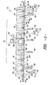
- Fig. 1 illustrates an embodiment of a vapor deposition system 10 that may incorporate various embodiments of a rotary feedthrough 100 in accordance with aspects of the invention, particularly as components for driving conveyors within various types of modules that make up the system 10.
- the system 10 of Fig. 1 is described below, followed by a detailed description of particular embodiments of the rotary feedthroughs 100.
- the system 10 is configured for deposition of a thin film layer on a photovoltaic (PV) module substrate 14 (referred to hereafter as "substrate").
- the thin film may be, for example, a film layer of cadmium telluride (CdTe).
- CdTe cadmium telluride
- a "thin" film layer on a PV module substrate is generally less than about 10 microns ( ⁇ m).
- the rotary feedthroughs 100 are not limited to use in the system 10 illustrated in Fig. 1 , but may be incorporated into vacuum processing line.
- the exemplary system 10 includes a vacuum chamber 12 defined by a plurality of interconnected modules, one or more of which include a rotary feedthrough 100 for providing rotational drive to an internal conveyor 48. Any combination of vacuum pumps 40 may be configured with the interconnected modules to draw and maintain a vacuum effective for the deposition process within the chamber 12.
- a plurality of interconnected heater modules 16 define a pre-heat section of the vacuum chamber 12 through which the substrates 14 are conveyed and heated to a desired temperature before being conveyed into a vapor deposition apparatus 60.
- Each of the heater modules 16 may include a plurality of independently controlled heaters 18, with the heaters defining a plurality of different heat zones. A particular heat zone may include more than one heater 18.
- the heaters 18 may be disposed above or below the module bodies.
- the vapor deposition apparatus 60 may take on various configurations and operating principles within the scope and spirit of the invention, and is generally configured for vapor deposition of a source material, such as CdTe, as a thin film on the PV module substrates 14.
- a source material such as CdTe
- the apparatus 60 is a module that includes a casing in which the internal components are contained, including a vacuum deposition head mounted above a conveyor assembly.
- the vacuum chamber 12 also includes a plurality of interconnected cool-down modules 20 within the vacuum chamber 12 downstream of the vapor deposition apparatus 60.
- the cool-down modules 20 define a cool-down section within the vacuum chamber 12 in which the substrates 14 having the thin film of source material deposited thereon are allowed to cool at a controlled cool-down rate prior to the substrates 14 being removed from the system 10.
- Each of the modules 20 may include a forced cooling system wherein a cooling medium, such as chilled water, refrigerant, or other medium is pumped through cooling coils configured with the modules 20.
- At least one post-heat module 22 is located immediately downstream of the vapor deposition apparatus 60 and before the cool-down modules 20.
- the leading section of a substrate 14 As the leading section of a substrate 14 is conveyed out of the vapor deposition apparatus 60, it moves into the post-heat module 22, which maintains the temperature of the substrate 14 at essentially the same temperature as the remaining portion of the substrate 14 within the vapor deposition apparatus 60. In this way, the leading section of the substrate 14 is not allowed to cool while the trailing section of the substrate 14 is still within the vapor deposition apparatus 60. If the leading section of a substrate 14 were allowed to cool as it exited the apparatus 60, a non-uniform temperature would be generated longitudinally along the substrate 14. This condition could result in the substrate breaking from thermal stress.
- a feed device 24 is configured with the vapor deposition apparatus 60 to supply source material, such as granular CdTe.
- the feed device 24 is configured so as to supply the source material without interrupting the continuous vapor deposition process within the apparatus 60 or conveyance of the substrates 14 through the apparatus 60.
- the individual substrates 14 are initially placed onto a load conveyor module 26, and are subsequently moved into an entry vacuum lock station that includes a load module 28 and a buffer module 30.
- a "rough" (i.e., initial) vacuum pump 32 is configured with the load module 28 to draw an initial vacuum
- a "fine” (i.e., high) vacuum pump 38 is configured with the buffer module 30 to increase the vacuum in the buffer module 30 to essentially the vacuum within the vacuum chamber 12.
- Valves 34 e.g., gate type slit valves or rotary-type flapper valves
- These valves 34 are sequentially actuated by a motor or other type of actuating mechanism 36 in order to introduce the substrates 14 (starting at atmospheric pressure) into the vacuum chamber 12 in a step-wise manner without affecting the vacuum within the chamber 12.
- An exit vacuum lock station is configured downstream of the last cool-down module 20, and operates essentially in reverse of the entry vacuum lock station described above.
- the exit vacuum lock station may include an exit buffer module 42 and a downstream exit lock module 44.
- Sequentially operated valves 34 are disposed between the buffer module 42 and the last one of the cool-down modules 20, between the buffer module 42 and the exit lock module 44, and between the exit lock module 44 and an exit conveyor module 46.
- a fine vacuum pump 38 is configured with the exit buffer module 42, and a rough vacuum pump 32 is configured with the exit lock module 44.
- the pumps 32, 38 and valves 34 are sequentially operated to move the substrates 14 out of the vacuum chamber 12 in a step-wise fashion without loss of vacuum condition within the vacuum chamber 12.
- System 10 also includes a coordinated conveyor system configured to move the substrates 14 into, through, and out of the vacuum chamber 12.
- this conveyor system includes a plurality of individually controlled conveyor assemblies 48, with each of the various modules in the system 10 including one of the conveyor assemblies 48.
- the respective conveyor assemblies 48 include a rotary feedthrough 100.
- each of the various modules and respective conveyors in the system 10 are independently controlled to perform a particular function.
- each of the individual modules may have an associated independent controller 50 configured therewith to control the individual functions of the respective module, including the conveyance rate of the conveyor assemblies 48 (and thus the speed of the rotary feedthroughs 100).
- the plurality of controllers 50 may, in turn, be in communication with a central system controller 52, as illustrated in Fig. 1 .
- the central system controller 52 can monitor and control (via the independent controllers 50) the functions of any one of the modules so as to achieve an overall desired heat-up rate, deposition rate, cool-down rate, and so forth, in processing of the substrates 14 through the system 10.
- the modules include active-sensing viewport assemblies 54 that detect the presence of the substrates 14 as they are conveyed through the module.
- the viewport assemblies 54 are in communication with the respective module controller 50, which is in turn in communication with the central controller 52.
- the viewport assemblies 54 may be in direct communication with the central controller 52 in an alternate embodiment.
- the individual respective conveyor assemblies 48/rotary feedthroughs 100 may be controlled to ensure that a proper spacing between the substrates 14 is maintained and that the substrates 14 are conveyed at the desired constant conveyance rate through the vacuum chamber 12. It should be appreciated that the viewport assemblies may be used for any other control function related to the individual modules or overall system 10.
- Fig. 2 illustrates an embodiment of a rotary feedthrough 100 in accordance with various aspects of the invention.
- the rotary feedthrough 100 is illustrated as configured on a side wall 104 of a vacuum chamber structure 102.
- the structure 102 may be one of the modules discussed above with respect to Fig. 1 , or may be any other type of vacuum chamber structure wherein it is desired to provide a rotational drive to components within the structure 102.
- the rotary feedthrough 100 is configured on the exterior of the chamber wall via an attachment pipe or other structure 105 that is permanently affixed to the chamber wall 104.
- the pipe 105 defines a bore 106 through the chamber wall 104 to provide access to internal components within the structure 102.
- the pipe 105 may include a mounting flange 107 to which the rotary feedthrough 100 is mounted. It should be appreciated that the pipe 105 and flange 107 configuration merely provides a means for mounting the rotary feedthrough 100 relative to the chamber wall 104. In an alternative embodiment, the bore 106 may be defined directly through the chamber wall 104 with the rotary feedthrough 100 mounted directly onto the exterior surface of the wall 104.
- the rotary feedthrough 100 includes a gearbox 108 having a housing 110. Internal components of the housing 110 are particularly illustrated in Figs. 3 and 4 and will be discussed in greater detail below.
- a motor 116 is operably coupled to the gearbox housing 110.
- the motor 116 may be electric, pneumatic, hydraulic, and the like.
- the motor 116 includes a motor drive shaft 118 that is geared to a shaft 123.
- the shaft 123 may be a single integral component, or may include an assembly of different shaft components.
- the shaft 123 extends from the gearbox housing 110 and into the vacuum chamber structure 102.
- the shaft 123 would extend through the pipe 105 and into the interior volume of the structure 102.
- a seal assembly 126 is operably disposed between the gearbox housing 110 and the chamber wall 104.
- the shaft 123 is disposed through this seal assembly prior to extending through the bore 106 and into the interior of the structure 102.
- the seal assembly 126 is configured for maintaining vacuum conditions within the interior of the structure 102.
- the seal assembly 106 includes any manner of suitable seal 142 that surrounds the shaft 123 within a seal assembly housing 140.
- the seal 142 may be, for example, an O-ring seal, face seal, lip seal, ferrofluidic seal, and the like. It should be appreciated that the invention is not limited to the particular type of seal 142 used within the seal housing 140.
- bearings 112 are contained within the gearbox housing 110 and rotationally support the shaft 123.
- a unique feature of the present rotary feedthrough 100 is that the bearings 112 within the gearbox housing 110 are the only set of bearings needed for rotational support of the shaft 123.
- the gearing arrangement between the motor and shaft 123 is selected to provide the desired gear ratio range for most rotary applications of the rotary feedthrough 100.
- a worm gear configuration is illustrated wherein a first worm gear component 122 is configured on the motor drive shaft 118 ( Fig.
- This worm gear arrangement provides for a simple yet robust gear configuration that provides the desired torque and speed functions for the rotary feedthrough 100. It should be appreciated, however, that other suitable gearing arrangements may be utilized.
- gearboxes 108 are within the scope and spirit of the invention, applicant has found that a suitable gearbox for use with the invention as described herein is a model no. C21Q56H-10 from Morse. Referring to Figs. 2 and 5 , this particular gearbox 108 includes a mounting flange 115 to which the motor 116 may be mounted, as illustrated in Fig. 2 .
- the housing includes a first flange 144 that connects to the gearbox housing 110 generally at the point where the shaft 123 extends from the housing.
- the seal assembly 126 includes an opposite flange 146 that mounts onto the exterior wall 104 of the structure 102, or structure associated with the exterior wall 104, such as the flange 107 extending from the pipe 105 as illustrated in Fig. 2 .
- the flange 146 includes over-sized bores 152 through which mounting bolts 150 extend.
- the oversized bores 152 allow for adjustment of the flange 146 relative to the bore 106 to accommodate for axial alignment of the shaft 123 relative to the internal components of the structure 102.
- a seal 148 is configured with the face of the flange 146 to provide a sealing interface between the flange 146 and the mounting flange 107 or other mounting structure associated with the chamber wall 104.
- the shaft 123 is assembled from multiple components.
- a hollow shaft 114 is disposed within the bearing housing 110 and is the component that is rotationally supported by the bearings 112.
- This hollow shaft component 114 also contains the worm gear component 120 that mates with the motor drive shaft 118.
- a second shaft component 124 is an elongated shaft member that extends at least partially into the hollow shaft 114 and is axially and rotationally fixed relative to the hollow shaft 114.
- the shaft component 124 extends completely through the hollow shaft 114 and includes a spline 130 that engages within a recess 128 defined longitudinally along the inner diameter surface of the hollow shaft 114. Engagement of the spline 130 within the recess 128 rotationally locks the components together.
- the shaft 124 is axially fixed relative to the hollow shaft 114 via a stop or shoulder 156 at one end of the gearbox housing 110 and a clamping ring 154 at the opposite end of the gearbox housing which surrounds the shaft component 124.
- the shaft 124 may be a solid component or, in alternate embodiments, may also be a hollow shaft component.
- the shaft 123 comprises multiple components
- the completed shaft assembly 123 is still only supported by a set of bearings 112 within the gearbox housing 110.
- the output shaft 124 is indirectly supported by the bearings via its configuration with the hollow shaft 114.
- the output shaft 124 is not otherwise directly supported by bearings.
- the embodiment wherein an output shaft 124 extends through a hollow shaft 114 within a gearbox is also beneficial in that the output shaft 124 may be readily pulled and replaced with shafts of varying sizes. This adds greater flexibility and versatility to use of the rotary feedthrough 100.
- the same gearbox 100 and motor 116 assembly may be configured for a particular manufacturing line, with variances between the particular uses of the feedthroughs 100 being accounted for by the different lengths of the output shafts 124. In this manner, a standardized repair/replacement gearbox 100 and/or motor 116 may be maintained in inventory.
Landscapes
- Engineering & Computer Science (AREA)
- Physics & Mathematics (AREA)
- Condensed Matter Physics & Semiconductors (AREA)
- General Physics & Mathematics (AREA)
- Manufacturing & Machinery (AREA)
- Computer Hardware Design (AREA)
- Microelectronics & Electronic Packaging (AREA)
- Power Engineering (AREA)
- Physical Vapour Deposition (AREA)
- Sealing Devices (AREA)
Applications Claiming Priority (1)
| Application Number | Priority Date | Filing Date | Title |
|---|---|---|---|
| US12/826,966 US20120000426A1 (en) | 2010-06-30 | 2010-06-30 | Integrated gearbox and rotary feedthrough system for a vacuum chamber structure |
Publications (2)
| Publication Number | Publication Date |
|---|---|
| EP2402986A2 true EP2402986A2 (de) | 2012-01-04 |
| EP2402986A3 EP2402986A3 (de) | 2014-04-30 |
Family
ID=44533559
Family Applications (1)
| Application Number | Title | Priority Date | Filing Date |
|---|---|---|---|
| EP11171400.2A Withdrawn EP2402986A3 (de) | 2010-06-30 | 2011-06-24 | Integriertes Getriebe und Drehschleusensystem für eine Vakuumkammerstruktur |
Country Status (4)
| Country | Link |
|---|---|
| US (1) | US20120000426A1 (de) |
| EP (1) | EP2402986A3 (de) |
| CN (1) | CN102315101A (de) |
| AU (1) | AU2011202981A1 (de) |
Family Cites Families (5)
| Publication number | Priority date | Publication date | Assignee | Title |
|---|---|---|---|---|
| US4768911A (en) * | 1987-09-01 | 1988-09-06 | Huntington Mechanical Laboratories, Inc. | Device for moving objects within and between sealed chambers |
| US5199483A (en) * | 1991-05-15 | 1993-04-06 | Applied Materials, Inc. | Method and apparatus for cooling wafers |
| US5139383A (en) * | 1991-07-23 | 1992-08-18 | Huntington Mechanical Laboratories, Inc. | Device for positioning objects within a sealed chamber |
| US6019164A (en) * | 1997-12-31 | 2000-02-01 | Temptronic Corporation | Workpiece chuck |
| JP4704605B2 (ja) * | 2001-05-23 | 2011-06-15 | 淳二 城戸 | 連続蒸着装置、蒸着装置及び蒸着方法 |
-
2010
- 2010-06-30 US US12/826,966 patent/US20120000426A1/en not_active Abandoned
-
2011
- 2011-06-21 AU AU2011202981A patent/AU2011202981A1/en not_active Abandoned
- 2011-06-24 EP EP11171400.2A patent/EP2402986A3/de not_active Withdrawn
- 2011-06-30 CN CN201110190351XA patent/CN102315101A/zh active Pending
Non-Patent Citations (1)
| Title |
|---|
| None |
Also Published As
| Publication number | Publication date |
|---|---|
| US20120000426A1 (en) | 2012-01-05 |
| AU2011202981A1 (en) | 2012-01-19 |
| EP2402986A3 (de) | 2014-04-30 |
| CN102315101A (zh) | 2012-01-11 |
Similar Documents
| Publication | Publication Date | Title |
|---|---|---|
| CN102127747A (zh) | 用于连续沉积薄膜层到基底上的模块系统和方法 | |
| TWI538075B (zh) | 用於氣相沉積系統中基板偵測之主動視域偵測組件 | |
| US20100224130A1 (en) | Rotating substrate support and methods of use | |
| CN111074239B (zh) | 一种lpcvd双材质真空反应室 | |
| US20110079963A1 (en) | Vacuum apparatus of rotary motion entry | |
| US8430963B2 (en) | Cool-down system and method for a vapor deposition system | |
| CN101956176A (zh) | 连续蒸镀设备 | |
| KR20190072389A (ko) | 냉각부재 및 진공코팅장비 | |
| EP2421033A2 (de) | Schlitzventil für einen Vakuumkammer-Modul | |
| EP2402986A2 (de) | Integriertes Getriebe und Drehschleusensystem für eine Vakuumkammerstruktur | |
| EP3026699B1 (de) | Anlage zum behandeln eines guts | |
| CN101378005A (zh) | 具有滚动隔膜的传递室 | |
| CN117966103B (zh) | 一种蒸发真空设备生产线 | |
| CN114686859B (zh) | 一种cvd工作台旋转装置及cvd装置 | |
| CN103602956B (zh) | 一种真空沉积系统及其旋转馈入装置 | |
| CN101358653A (zh) | 磁流体隔热装置及隔热系统 | |
| CN116330567B (zh) | 一种导热油内循环式薄膜加热辊 | |
| US20140110225A1 (en) | Conveyor assembly with geared, removable rollers for a vapor deposition system | |
| CN221701629U (zh) | 一种用于真空镀膜的输送装置和生产线 | |
| CN103464084A (zh) | 间歇式固相增粘装置 | |
| CN215799758U (zh) | 一种用于环形炉的驱动装置 | |
| US20120024233A1 (en) | Conveyor Assembly with Releasable Drive Coupling | |
| CN221566319U (zh) | 传输机构以及镀膜设备 | |
| CN222684749U (zh) | 镀膜装置以及镀膜设备 | |
| CN217265406U (zh) | 一种玻璃制品带有温度调节的供料装置 |
Legal Events
| Date | Code | Title | Description |
|---|---|---|---|
| AK | Designated contracting states |
Kind code of ref document: A2 Designated state(s): AL AT BE BG CH CY CZ DE DK EE ES FI FR GB GR HR HU IE IS IT LI LT LU LV MC MK MT NL NO PL PT RO RS SE SI SK SM TR |
|
| AX | Request for extension of the european patent |
Extension state: BA ME |
|
| PUAI | Public reference made under article 153(3) epc to a published international application that has entered the european phase |
Free format text: ORIGINAL CODE: 0009012 |
|
| RAP1 | Party data changed (applicant data changed or rights of an application transferred) |
Owner name: FIRST SOLAR MALAYSIA SDN.BHD |
|
| PUAL | Search report despatched |
Free format text: ORIGINAL CODE: 0009013 |
|
| AK | Designated contracting states |
Kind code of ref document: A3 Designated state(s): AL AT BE BG CH CY CZ DE DK EE ES FI FR GB GR HR HU IE IS IT LI LT LU LV MC MK MT NL NO PL PT RO RS SE SI SK SM TR |
|
| AX | Request for extension of the european patent |
Extension state: BA ME |
|
| RIC1 | Information provided on ipc code assigned before grant |
Ipc: H01L 21/68 20060101ALI20140327BHEP Ipc: H01L 21/67 20060101ALI20140327BHEP Ipc: H01L 21/677 20060101AFI20140327BHEP |
|
| STAA | Information on the status of an ep patent application or granted ep patent |
Free format text: STATUS: THE APPLICATION IS DEEMED TO BE WITHDRAWN |
|
| 18D | Application deemed to be withdrawn |
Effective date: 20141031 |