EP2402884A2 - Image processing device and image processing method - Google Patents
Image processing device and image processing method Download PDFInfo
- Publication number
- EP2402884A2 EP2402884A2 EP11167246A EP11167246A EP2402884A2 EP 2402884 A2 EP2402884 A2 EP 2402884A2 EP 11167246 A EP11167246 A EP 11167246A EP 11167246 A EP11167246 A EP 11167246A EP 2402884 A2 EP2402884 A2 EP 2402884A2
- Authority
- EP
- European Patent Office
- Prior art keywords
- subject
- frame
- image
- section
- tracking
- Prior art date
- Legal status (The legal status is an assumption and is not a legal conclusion. Google has not performed a legal analysis and makes no representation as to the accuracy of the status listed.)
- Withdrawn
Links
Images


Classifications
-
- G—PHYSICS
- G06—COMPUTING OR CALCULATING; COUNTING
- G06V—IMAGE OR VIDEO RECOGNITION OR UNDERSTANDING
- G06V10/00—Arrangements for image or video recognition or understanding
- G06V10/20—Image preprocessing
- G06V10/22—Image preprocessing by selection of a specific region containing or referencing a pattern; Locating or processing of specific regions to guide the detection or recognition
- G06V10/235—Image preprocessing by selection of a specific region containing or referencing a pattern; Locating or processing of specific regions to guide the detection or recognition based on user input or interaction
-
- G—PHYSICS
- G06—COMPUTING OR CALCULATING; COUNTING
- G06T—IMAGE DATA PROCESSING OR GENERATION, IN GENERAL
- G06T7/00—Image analysis
- G06T7/70—Determining position or orientation of objects or cameras
- G06T7/73—Determining position or orientation of objects or cameras using feature-based methods
- G06T7/74—Determining position or orientation of objects or cameras using feature-based methods involving reference images or patches
-
- G—PHYSICS
- G06—COMPUTING OR CALCULATING; COUNTING
- G06V—IMAGE OR VIDEO RECOGNITION OR UNDERSTANDING
- G06V10/00—Arrangements for image or video recognition or understanding
- G06V10/20—Image preprocessing
- G06V10/255—Detecting or recognising potential candidate objects based on visual cues, e.g. shapes
-
- H—ELECTRICITY
- H04—ELECTRIC COMMUNICATION TECHNIQUE
- H04N—PICTORIAL COMMUNICATION, e.g. TELEVISION
- H04N23/00—Cameras or camera modules comprising electronic image sensors; Control thereof
- H04N23/60—Control of cameras or camera modules
- H04N23/61—Control of cameras or camera modules based on recognised objects
- H04N23/611—Control of cameras or camera modules based on recognised objects where the recognised objects include parts of the human body
-
- H—ELECTRICITY
- H04—ELECTRIC COMMUNICATION TECHNIQUE
- H04N—PICTORIAL COMMUNICATION, e.g. TELEVISION
- H04N23/00—Cameras or camera modules comprising electronic image sensors; Control thereof
- H04N23/60—Control of cameras or camera modules
- H04N23/62—Control of parameters via user interfaces
-
- G—PHYSICS
- G06—COMPUTING OR CALCULATING; COUNTING
- G06V—IMAGE OR VIDEO RECOGNITION OR UNDERSTANDING
- G06V10/00—Arrangements for image or video recognition or understanding
- G06V10/40—Extraction of image or video features
- G06V10/62—Extraction of image or video features relating to a temporal dimension, e.g. time-based feature extraction; Pattern tracking
-
- G—PHYSICS
- G06—COMPUTING OR CALCULATING; COUNTING
- G06V—IMAGE OR VIDEO RECOGNITION OR UNDERSTANDING
- G06V40/00—Recognition of biometric, human-related or animal-related patterns in image or video data
- G06V40/10—Human or animal bodies, e.g. vehicle occupants or pedestrians; Body parts, e.g. hands
- G06V40/16—Human faces, e.g. facial parts, sketches or expressions
- G06V40/161—Detection; Localisation; Normalisation
-
- H—ELECTRICITY
- H04—ELECTRIC COMMUNICATION TECHNIQUE
- H04N—PICTORIAL COMMUNICATION, e.g. TELEVISION
- H04N2101/00—Still video cameras
-
- H—ELECTRICITY
- H04—ELECTRIC COMMUNICATION TECHNIQUE
- H04N—PICTORIAL COMMUNICATION, e.g. TELEVISION
- H04N23/00—Cameras or camera modules comprising electronic image sensors; Control thereof
- H04N23/60—Control of cameras or camera modules
- H04N23/63—Control of cameras or camera modules by using electronic viewfinders
- H04N23/633—Control of cameras or camera modules by using electronic viewfinders for displaying additional information relating to control or operation of the camera
- H04N23/635—Region indicators; Field of view indicators
Definitions
- the present disclosure relates to an image processing device and an image processing method, and in particular to an image processing device and an image processing method where it is possible to recognize a subject which is a tracking target with precision.
- digital cameras In the past, in digital still cameras, digital video cameras, and the like (referred to appropriately below as digital cameras), a function for tracking a subject such as the face of a certain person selected by a user or an object other than a face was mounted. Then, it is possible to continuously maintain various parameters (for example, focus, brightness, and the like) of the digital camera to be optimal according to the state of the position of a tracking subject.
- various parameters for example, focus, brightness, and the like
- a method for the user to select a subject to be photographed using a digital camera there is a method for selecting by touching a subject displayed on a touch panel, a method for selecting using a guide frame for matching a subject with the angle of view in advance, and the like.
- an imaging device in which, when the user wants to track a subject other than a face, a dedicated mode in which it is possible to detect the subject is set to operate, and a subject tracking function is enabled.
- An image processing device is provided with a subject frame setting section which, by operating a subject detector which detects a subject captured in an image, sets a subject frame which surrounds a predetermined range of the subject detected from the image; an acceptance frame setting section which sets an acceptance frame with a range wider than the subject frame according to the context of the image; a position detecting section which detects a specified position on an image which is specified by a user; and a recognizing section which recognizes a subject which is a tracking target based on the acceptance frame set by the acceptance frame setting section and the specified position detected by the position detecting section.
- An image processing method includes setting, by operating a subject detector which detects a subject captured in an image, a subject frame which surrounds a predetermined range of the subject detected from the image; setting an acceptance frame with a range wider than the subject frame according to the context of the image; detecting a specified position on an image which is specified by a user; and recognizing a subject which is a tracking target based on the acceptance frame and the specified position.
- the subject frame which surrounds the predetermined range of the subject detected from the image is set by operating the subject detector which detects the subject captured in the image and the acceptance frame with a range wider than the subject frame is set according to the context of the image. Then, the specified position on the image which is specified by the user is detected and the subject which is the tracking target is recognized based on the acceptance frame and the specified position.
- An image processing device is provided with a subject frame setting section which, by operating a subject detector which detects a subject captured in an image, sets a subject frame which surrounds a predetermined range of the subject detected from the image; an acceptance frame setting section which sets an acceptance frame with a range wider than the subject frame according to an imaging mode set for performing imaging using imaging conditions which are appropriate for a certain image; a position detecting section which detects a specified position on an image which is specified by a user; and a recognizing section which recognizes a subject which is a tracking target based on the acceptance frame set by the acceptance frame setting section and the specified position detected by the position detecting section.
- An image processing method includes setting, by operating a subject detector which detects a subject captured in an image, a subject frame which surrounds a predetermined range of the subject detected from the image; setting an acceptance frame with a range wider than the subject frame according to an imaging mode set for performing imaging using imaging conditions which are appropriate for a certain image; detecting a specified position on an image which is specified by a user; and recognizing a subject which is a tracking target based on the acceptance frame and the specified position.
- the subject frame which surrounds the predetermined range of the subject detected from the image is set by operating the subject detector which detects the subject captured in the image and the acceptance frame with a range wider than the subject frame is set according to the imaging mode set for performing imaging using the imaging conditions which are appropriate for a certain subject. Then, the specified position on the image which is specified by the user is detected and the subject which is the tracking target is recognized based on the acceptance frame and the specified position.
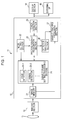
- Fig. 1 is a block diagram illustrating a configuration example of a digital camera according to an embodiment of the disclosure.
- a digital camera 11 is configured to be provided with a lens 12, an imaging section 13, a display section 14, an external I/F (interface) 15, and an image processing section 16.
- the lens 12 is configured by, for example, a group of a plurality of lenses which provided a zoom function and the like, and light from a subject is concentrated and an image of a subject is produced on an imaging surface of an imaging element of the imaging section 13.
- the imaging section 13 is configured by, for example, a CCD (Charge Coupled Device), a CMOS (Complementary Metal Oxide Semiconductor) sensor, or the like, and images the image of the subject and outputs the image obtained via the imaging to the image processing section 16.
- the display section 14 is configured by an LCD (Liquid Crystal Display), an organic EL (Electro Luminescence) display, or the like, and the image which is imaged in the imaging section 13 and output by imaging processing being carried out in the image processing section 16, that is, the image where the subject is surrounded by a subject frame, is displayed.
- the external I/F 15 is configured by a terminal or the like for outputting the image output from the image processing section 16 to, for example, an external display (not shown).
- the image processing section 16 carries out image processing with regard to the image imaged by the imaging section 13 and outputs the image to the display section 14 and the external I/F 15.
- the image processing section 16 performs image processing where, for example, a subject (for example, a face) which is captured in an image is detected and a subject frame which surrounds a predetermined range of the subject is synthesized in the image.
- a subject tracking process where the subject is tracked and performs a process where various types of parameters are adjusted so each is optimal when the subject which is a tracking target (referred to below as tracking subject) is imaged.
- the image processing section 16 is configured to be provided with an image memory 21, a mode setting section 22, a touch detection section 23, a subject frame setting processing section 24, a tracking subject recognition section 25, a detector switching section 26, and a subject tracking processing section 27.
- image memory 21 data of the image imaged by the imaging section 13 is sequentially supplied, and the image memory 21 sequentially stores the supplied data of the image.
- the mode setting section 22 sets the various types of parameters used in the imaging mode specified by a user.
- the digital camera 11 is provided with, for example, various imaging modes such as a person mode where imaging is performed using imaging conditions which are appropriate for images of people, a pet mode where imaging is performed using imaging conditions which are appropriate for images of animals, and the like.
- the imaging mode which is set in the mode setting section 22 is referenced in processes which are performed by the subject frame setting processing section 24 and the tracking subject recognition section 25.
- the touch detection section 23 detects a position (specified position) which is touched when a user touches the screen of the display section 14 based on a signal from a touch panel (not shown) which is installed so as to overlap with the screen of the display section 14. Then, the touch detection section 23 supplies information showing the touch position to the tracking subject recognition section 25.
- the subject frame setting processing section 24 has a plurality of detectors which detect a subject captured in an image and performs a subject frame setting process where the size of a subject frame, which surrounds a predetermined range of the subject detected by the detectors, is set.
- the subject frame setting processing section 24 has a face detector 28-1 and an animal detector 28-2 and sets the subject frame with regard to the face of a person detected by the face detector 28-1, the face of an animal detected by the animal detector 28-2, or the like.
- the subject frame set by the subject frame setting processing section 24 is synthesized in the image and is displayed in the display section 14.
- the tracking subject recognition section 25 recognizes the tracking subject based on the subject frame set by the subject frame setting processing section 24 when the information showing the touch position touched by a user is supplied from the touch detection section 23. For example, the tracking subject recognition section 25 recognizes the subject which is set in the subject frame as the tracking subject if the touch position touched by the user is at an inner side of the subject frame. Then, the tracking subject recognition section 25 supplies the information where the tracking subject is specified to the detector switching section 26 in a case where it is possible to recognize the tracking subject.
- the detector switching section 26 recognizes the detector used by the subject frame setting processing section 24 in the detection of the tracking subject via the tracking subject recognition section 25 when the information specifying the tracking subject is supplied from the tracking subject recognition section 25. Then, the detector switching section 26 performs a process of supplying the information specifying the tracking subject to the subject tracking processing section 27 and switching the detector used by the subject tracking processing section 27 in the subject tracking process to the detector used in the detection of the tracking subject.
- the subject tracking processing section 27 starts the subject tracking process where the tracking subject which is specified by the information which specifies the tracking subject is tracked using the detector which is switched by the detector switching section 26. According to this, it is possible for the subject tracking processing section 27 to execute the subject tracking process using the detector which is appropriate for the tracking subject.
- the subject tracking processing section 27 detects a region, which has color and luminance close to that of the tracking subject in a predetermined region in the vicinity of the position of the tracking subject specified in the previous image, in the next image and specifies the tracking target. Then, the subject tracking processing section 27 repeatedly performs specification of the tracking subject from the image sequentially stored in the image memory 21 based on the position of the tracking subject specified by the image and the color and the luminance of the tracking subject. In this manner, the subject tracking process is performed and the subject tracking processing section 27 adjusts the various types of parameters so that each is optimal when the tracking subject is imaged.
- the subject which has become the tracking target is recognized by the user touching the screen of the display section 14 and the subject tracking process where the subject is tracked is performed.
- the tracking subject recognizing section 25 it is not possible for the tracking subject recognizing section 25 to recognize the tracking subject in a case where the touch position touched by the user is not at an inner side of any of the subject frames. In this case, it is possible for the tracking subject recognizing section 25 to reference the imaging mode set by the mode setting section 22 and recognize the tracking subject.
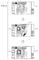
- Screens P11 to P13 of the display section 14 when the person mode is set as the imaging mode are shown in Fig. 2
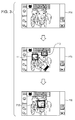
- screens P14 to P16 of the display section 14 when the pet mode is set as the imaging mode are shown in Fig. 3 .
- the face detector 28-1 normally operates in the subject frame setting processing section 24.
- the subject frame setting processing section 24 sets the subject frame to the faces of the two children detected by the face detector 28-1. According to this, as shown screen P12, a subject frame F11 and a subject frame F12 set in regard to the faces of the two children are displayed.
- the position where the user touches the screen of the display section 14 is an outer-side vicinity of the subject frame F11 such as the tip of the finger mark shown in screen P12 and is in the vicinity of the dog.
- the tracking subject recognizing section 25 since the imaging mode is the person mode, the tracking subject recognizing section 25 infers that the subject which the user wants as the tracking target is the person even in an outer side of the subject frame F11, and the face of the child where the subject frame F11 is set is recognized as the tracking subject. According to this, as shown in screen P13, a subject frame F11' for the tracking subject is displayed. The color, size, and the like from the previous subject frame F11 which was recognized as the tracking target is changed and the subject frame F11' for the tracking subject is displayed.
- screens P14 to P16 of the display section 14 when the imaging mode is the pet mode an icon showing an animal and "pet mode" are displayed.
- screen P14 an image with the same configuration as screen P11 of Fig. 2 is displayed, and as shown in screen P15, a location which is in an outer-side vicinity of the subject frame F11 and in the vicinity of the dog (the same location as in screen P12 of Fig. 2 ) is touched by the user.
- the tracking subject recognizing section 25 infers that the subject which the user wants as the tracking target is the animal and not the children even in an outer side of the subject frame F11 and the dog is recognized as the tracking subject. According to this, as shown in screen P16, a subject frame F13' for the tracking subject which surrounds a predetermined region of the face of the dog is displayed.
- both the face detector 28-1 and the animal detector 28-2 operate at the same time.
- the plurality of detectors in the digital camera 11 operates at the same time, it is possible to display the subject frames with regard to the subjects which are detected by the respective detectors.
- the region which stipulates the vicinity is determined.
- a frame where the spacing changes may be set according to the imaging target, the imaging mode, or the like.
- the frame, where it is acceptable for the subject which is set in the subject frame, to be touched by the user, even when the position where the user touches the screen of the display section 14 is an outer-side of the subject frame is appropriately referred to below as the touch acceptance frame.
- screen P17 of the display section 14 when the person mode is set as the imaging mode and screen P18 of the display section 14 when the pet mode is set as the imaging mode are shown.
- Screens P17 and P18 are where a person and a dog are imaged and have the same configuration.
- a subject frame F14 with regard to the face of the person and a subject frame F15 with regard to the face of the dog are set as the same locations.
- a touch acceptance frame F16 with regard to the subject frame F14 and a touch acceptance frame F17 with regard to the subject frame F15 are shown with dashed lines.
- the touch acceptance frames F16 and F17 are diagrammatically shown in order for description and are not shown in the display section 14.
- the touch acceptance frame F16 where there is the setting of the subject frame F14 of the face of the person which is the subject appropriate to the imaging mode is set to be larger than the touch acceptance frame F17 where there is the setting of subject frame F15 of the face of the dog.
- the touch acceptance frame F17 where there is the setting of the subject frame F15 of the face of the dog which is the subject appropriate to the imaging mode is set to be larger than the touch acceptance frame F16 where there is the setting of subject frame F14 of the face of the person.
- the spacing of the touch acceptance frame F16 with regard to the subject frame F14 is set so that the spacing on the lower side with regard to the subject frame F14 is wider than the spacing on the upper side, right side, and left side with regard to the subject frame F14.
- the spacing on the lower side of the touch acceptance frame F16 with regard to the subject frame F14 is set to be wide, it is also possible to set the person as the tracking subject when the body of the person captured in the image is touched.
- the touch acceptance frame F17 is set so as to have equal spacing with regard to the subject frame F15.
- the size of the touch acceptance frame according to the type of the subject specifically, the size of the touch acceptance frame according to the type of detector which detects the subject is set in advance.
- the size of the subject frame is adjusted according to the size of the subject captured in the image and the size of the touch acceptance frame is adjusted according to the size of the subject frame.
- a subject frame F18 which is set for the subject A is set to be larger than a subject frame F20 which is set for the subject B.
- a touch acceptance frame F19 which is set for the subject A is also set to be larger than a touch acceptance frame F21 which is set for the subject B.
- the touch acceptance frame F19 is set so that the spacing (margin) on the lower side of the touch acceptance frame F19 with regard to the subject frame F18 is wider than the spacing on the upper side, right side, and left side, so as to include the body of the subject B.
- the touch acceptance frame F21 is set so that the spacing on the lower side with regard to the subject frame F20 is wide so as to include the body of the subject B.
- the spacing of the touch acceptance frame with regard to the subject frame may be adjusted, for example, according to the movement of the subject, according to the context (scene) of the subject.
- the spacing on the left side of the touch acceptance frame F19 (the subject B side) which is set for the subject A is adjusted so as to become narrower.
- the touch acceptance frame F19 is adjusted to return to the original spacing.
- the spacing on the subject A side of the touch acceptance frame F21 which is also set for the subject B is adjusted so as to become narrower as the subject B approaches the subject A and is adjusted to return to the original spacing when the subject B separates from the subject A.
- the spacing on both sides of the touch acceptance frame F19 which is set for the subject A is adjusted so as to become narrower.
- the touch acceptance frame F19 is adjusted to return to the original spacing.
- the touch acceptance frame F21 which is set for the subject B and a touch acceptance frame F23 which is set for the subject C are adjusted according to the movement of the subject B and the subject C.
- the touch acceptance frame is set so as to surround a wider range than the subject frame, and the size of the touch acceptance frame is adjusted due to the imaging mode and the imaging scene (the size, type, movement, and the like of the subject).
- Fig. 9 is a block diagram illustrating a configuration example of the tracking subject recognition section 25 which sets the touch acceptance frame.
- the tracking subject recognition section 25 is configured to be provided with a storage section 31, a movement detection section 32, a touch acceptance frame setting processing section 33, a touch determination section 34, and a recognition section 35.
- information relating to the subject frame set by the subject frame setting processing section 24 is supplied, and information relating to the subject frame is stored in the storage section 31 for a predetermined period.
- information relating to the subject frame information which shows the position and the size of the subject frame and information which shows the type of the detector which detects the subject are included.
- the movement detection section 32 detects movement of the subject by determining a change in position of the subject frame in a predetermined period based on the information relating to the subject frame stored in the storage section 31.
- the touch acceptance frame setting processing section 33 sets the touch acceptance frame with regard to the subject frame based on the imaging mode set by the mode setting section 22 and the information relating to the subject frame stored in the storage section 31. In addition, the touch acceptance frame setting processing section 33 adjusts the size of the set touch acceptance frame based on movement of the subject frame which is detected by the movement detection section 32.
- the touch determination section 34 determines whether or not the touch position is in the range of the touch acceptance frame which is set by the touch acceptance frame setting processing section 33. Then, in a case where it is determined that the touch position is in the range of the touch acceptance frame, the touch determination section 34 decides that the subject where the touch acceptance frame is set is the tracking subject and notifies the recognition section 35.
- the touch determination section 34 operates the other detectors with regard to the subject frame setting processing section 24. For example, when only the face detector 28-1 is operated, there is a case where the user touches the subject other than the person, for example, the animal. At this time, it is determined that the touch position is not in the range of the touch acceptance frame, but by operating the animal detector 28-2 using the subject frame setting processing section 24, it is possible to detect the animal which is touched by the user and it is possible to recognize the animal as the tracking subject.
- the recognition section 35 recognizes the tracking subject when there is notification of the tracking subject from the touch determination section 34 and outputs information which specifies the tracking subject.
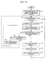
- Fig. 10 is a flow chart describing a process where the digital camera 11 starts subject tracking.
- the process starts when the digital camera 11 is activated and the imaging using the imaging section 13 starts, and in step S11, the subject frame setting processing section 24 starts operating the face detector 28-1. Then, the subject frame setting processing section 24 starts the subject frame setting process where the subject frame (face frame) is set with regard to the face of the person which is detected from the image stored in the image memory 21, and the process progresses to step S12.
- step S12 the touch detection section 23 determines whether or not the user touches the screen of the display section 14 based on the signal from the touch panel of the display section 14. Then, the process waits until the touch detection section 23 determines that the user has touched the screen of the display section 14, and when it is determined that the user has touched the screen of the display section 14, the process progresses to step S13.
- step S13 the touch detection section 23 outputs the information (coordinates) which shows the touch position touched by the user to the tracking subject recognition section 25 and the tracking subject recognition section 25 acquires the touch position.
- step S14 the touch acceptance frame setting process (refer to Fig. 11 described later) is performed, and the touch acceptance frame is set with regard to the subject frame.
- step S15 the process progresses to step S15.
- step S15 in the tracking subject recognition section 25, the touch determination section 34 determines whether or not the touch position is in the range of the touch acceptance frame based on the touch position acquired in step S13.
- step S15 In a case where it is determined in step S15 that the touch position is not in the range (outside of the range) of the touch acceptance frame, the process progresses to step S16, and the touch determination section 34 determines whether or not all of the detectors of the subject frame setting processing section 24 are operating.
- step S16 In a case where it is determined in step S16 that not all of the detectors of the subject frame setting processing section 24 are operating, the process progresses to step S17.
- step S17 the touch determination section 34 requests operation of the detectors other than the detectors which are operating with regard to the subject frame setting processing sector 24.
- the subject frame setting processing section 24 starts the operation of the other detectors, the process returns to step S14, and below, the process is repeated in the same manner. That is, the detection of the subject using the detectors which have begun operating is performed, the subject frame is set when the subject is newly detected, and the touch acceptance frame is newly set with regard to the subject frame.
- step S16 determines that all of the detectors of the subject frame setting processing section 24 are operating.
- the process returns to step S12, and below, the process is repeated in the same manner. That is, in this case, it is not possible for the tracking subject to be recognized with regard to the touch of the user, and the detection of a new touch is awaited.
- the tracking subject may be displayed on the display section 14.
- step S15 determines that the touch position is in the range of the touch acceptance frame.
- step S18 the recognition section 35 recognizes the subject, which is set in the touch acceptance frame in which the touch position is in the range, as the tracking subject and acquires the color and luminance in the subject frame set for the subject. Then, the recognition section 35 supplies information, which includes information which shows the position of the tracking subject, and information which shows the color and the luminance of the tracking subject and the like and which specifies the tracking subject, to the detector switching section 26.
- step S19 the detector switching section 26 performs a process of recognizing the detector which detects the tracking subject and switching the detector with regard to the subject tracking processing section 27 so as to use the detector in the subject tracking process.
- the detector switching section 26 supplies the information which specifies the tracking subject to the subject tracking processing section 27 and the process progresses to step S20.
- step S20 the subject tracking processing section 27 uses the detector switched in step S18 and the subject tracking process where the tracking subject is tracked starts based on the information which specifies the tracking subject. After the process of step S20, the process returns to step S12, the process waits until the user touches the next subject, and below, the process is repeated in the same manner.
- the imaging mode is the person mode and only the face detector 28-1 is operating
- the operation of the animal detector 28-2 automatically starts and the animal is recognized as the tracking subject. In this manner, it is no bother for the user to change the imaging mode to the animal mode and it is possible to start the subject tracking process with the animal as the tracking subject.
- the detector switching section 26 to stop the operation of the detectors other than the detector used in the detection of the tracking subject. According to this, it is possible to reduce the processing which is executed in the image processing section 16, and for example, it is possible to suppress the use of power.
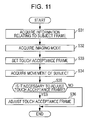
- Fig. 11 is a flow chart describing the touch acceptance frame setting process of step S14 of Fig. 10 .
- step S31 the touch acceptance frame setting processing section 33 reads out and acquires the information, which relates to the subject frame displayed in the display section 14 at a timing when the touch determination section 34 acquires the touch position, from the storage section 31.
- step S32 the touch acceptance frame setting processing section 33 references the mode setting section 22, the imaging mode which is currently set is acquired, and the process progresses to step S33.
- step S33 the touch acceptance frame setting processing section 33 recognizes the type of the subject where the subject frame is set based on the information relating to the subject frame acquired in step S31. Then, the touch acceptance frame setting processing section 33 sets the touch acceptance frame with regard to the subject frame in a size which is a standard registered in advance based on the type of the recognized subject and the imaging mode acquired in step S32.
- the size, which is the standard of the touch acceptance frame with regard to the size of the subject frame is registered in advance.
- the size of the touch acceptance frame with regard to the subject frame differs in accordance with the type of the subject for each of the imaging modes as described with reference to Fig. 5
- the size, which is the standard of the touch acceptance frame with regard to the subject frame is registered for each of the imaging modes.
- step S34 the touch acceptance frame setting processing section 33 references the movement detection section 32 and acquires the movement of the subject, and in step S35, it is determined whether or not it is necessary to adjust the touch acceptance frame set to the size which is the standard.
- the touch acceptance frames are adjusted so that the spacing of the touch acceptance frames with regard to the subject frame on the opposing sides of each of the subjects become narrower.
- the touch acceptance frame is adjusted so that the narrowed spacing is widened. Accordingly, the touch acceptance frame setting processing section 33 determines whether it is necessary to adjust the touch acceptance frame in the case where movement of the subjects is detected in this manner.
- step S35 In a case where it is determined in step S35 that it is necessary to adjust the touch acceptance frame, the process progresses to step S36, the touch acceptance frame setting processing section 33 adjusts the touch acceptance frame according to movement of the subject, and the process is completed.
- step S35 determines that it is not necessary to adjust the touch acceptance frame.
- the touch acceptance frame setting processing section 33 sets the size of the touch acceptance frame according to the imaging mode, it is possible for the subject which is prioritized and imaged in each of the imaging modes to be recognized as the tracking subject with priority.
- the touch acceptance frame setting processing section 33 adjusts the touch acceptance frame according to the imaging scene (that is, the context of the imaged image), more specifically, according to characteristics of the subject captured in the image (type, size, and the like), movement of the subject relative to each other, or the like. According to this, it is possible to recognize the subject which is appropriate for each of the imaging scenes as the tracking subject with priority.
- the digital camera 11 is provided with the imaging mode other than the person mode and the pet mode described above, and for the subject frame setting processing section 24 and the tracking subject recognition section 25 to set the subject frame and the touch acceptance frame for the subject which is prioritized in imaging for each of the imaging modes.
- the digital camera 11 is provided with a child prioritizing mode which performs imaging with imaging conditions which are appropriate for imaging children, an adult prioritizing mode which performs imaging with imaging conditions which are appropriate for imaging adults, or the like.
- Screen P19 of the display section 14 when the child prioritizing mode is set as the imaging mode and screen P20 of the display section 14 when the adult prioritizing mode is set as the imaging mode are shown in Fig. 12 .
- Screens P19 and P20 have the same configuration where two children and one adult are captured, subject frames F24 and F25 are displayed for the faces of the children and a subject frame F26 is displayed for the face of the adult.
- screens P19 and P20 such as these, there is a case where the position where the user touches the screen of the display section 14 is between the subject frames F25 and F26 in the same manner as the tip of the finger mark shown in screens P19 and P20.
- the imaging mode is the child prioritizing mode
- the child which is set with the subject frame F25 is recognized as the tracking subject
- the imaging mode is the adult prioritizing mode
- the adult which is set with the subject frame F26 is recognized as the tracking subject.
- the digital camera 11 is provided with the imaging modes such as an underwater mode, a food mode, a flower mode, or the like, the subject frame is set with regard to the subject that is appropriate for each of the imaging modes, and the touch acceptance frame is adjusted. That is, other than the face detector 28-1 and the animal detector 28-2 shown in Fig. 1 , it is possible for the subject frame setting processing section 24 to be provided with a fish detector, a food detector, a flower detector, or the like. As the animal detector 28-2, there may be a dog face detector and a cat face detector. In addition, the digital camera 11 may be provided with a scenery mode, a night scene mode, or the like as the imaging mode.
- the imaging modes such as an underwater mode, a food mode, a flower mode, or the like
- the subject frame is set with regard to the subject that is appropriate for each of the imaging modes, and the touch acceptance frame is adjusted. That is, other than the face detector 28-1 and the animal detector 28-2 shown in Fig. 1 , it is possible for the subject frame setting
- the imaging modes are automatically set so as to perform optimal imaging according to the imaging context by analyzing the image in the digital camera 11.
- the face detector 28-1 is normally operating, but there may be a state where the detector is not normally operating in this manner and the subject frame is not displayed on the display section 14 before being touched by the user. That is, the operation of the detectors may be started at a timing when there is a touch by the user.
- the subject to be tracked is selected by the user touching the screen of the display section 14, but the subject may be selected by another means, for example, by operation of operation keys.
- the subject may be selected by using a guide frame for matching the subject with the angle of view in advance.
- the digital camera such as a digital still camera, a digital video camera, or the like
- an imaging function such as a mobile phone device, a personal computer, or the like.
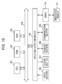
- Fig. 13 is a block diagram illustrating a configuration example of hardware of a computer which executes the series of processes described above using a program.
- a CPU Central Processing Unit
- ROM Read Only Memory
- RAM Random Access Memory
- an input and output interface 105 is further connected.
- an input section 106 formed by a keyboard, a mouse, a microphone, or the like
- an output section 107 formed by a display, a speaker, or the like
- a storage section 108 formed by a hard disk, a nonvolatile memory, or the like
- a communication section 109 formed by a network interface or the like
- a drive 110 which drives a magnetic disk, an optical disc, a magneto-optical disc, or a removable medium 111 such as a semiconductor memory or the like, are connected.
- the CPU 101 performs the series of processes described above by, for example, executing the loading of the program stored in the storage section 108 in the RAM 103 via the input and output interface 105 and the bus 104.
- the program executed by the computer (CPU 101) is, for example, recorded in a magnetic disk (including a flexible disk), an optical disc (a CD-ROM (Compact Disc-Read Only Memory), a DVD (Digital Versatile Disc), or the like), a magneto-optical disc, or the removable medium 111 formed by a semiconductor memory or the like such as a package medium, or is provided via a wired or wireless transmission medium such as a local area network, the internet, or digital satellite broadcasting.
- a magnetic disk including a flexible disk
- an optical disc a CD-ROM (Compact Disc-Read Only Memory), a DVD (Digital Versatile Disc), or the like
- a magneto-optical disc or the removable medium 111 formed by a semiconductor memory or the like such as a package medium, or is provided via a wired or wireless transmission medium such as a local area network, the internet, or digital satellite broadcasting.
- the program executed by the computer may be a program which performs the processes in a time series in the sequence described in the specifications or may be a program which performs the processes in parallel or at a necessary timing such as when a request is performed.
- the program may be processed using one CPU or may be distributed and processed using a plurality of CPUs.
Landscapes
- Engineering & Computer Science (AREA)
- Multimedia (AREA)
- Signal Processing (AREA)
- Physics & Mathematics (AREA)
- General Physics & Mathematics (AREA)
- Theoretical Computer Science (AREA)
- Human Computer Interaction (AREA)
- Computer Vision & Pattern Recognition (AREA)
- Studio Devices (AREA)
- Exposure Control For Cameras (AREA)
- Indication In Cameras, And Counting Of Exposures (AREA)
- Image Analysis (AREA)
Abstract
Description
- The present disclosure relates to an image processing device and an image processing method, and in particular to an image processing device and an image processing method where it is possible to recognize a subject which is a tracking target with precision.
- In the past, in digital still cameras, digital video cameras, and the like (referred to appropriately below as digital cameras), a function for tracking a subject such as the face of a certain person selected by a user or an object other than a face was mounted. Then, it is possible to continuously maintain various parameters (for example, focus, brightness, and the like) of the digital camera to be optimal according to the state of the position of a tracking subject.
- As a method for the user to select a subject to be photographed using a digital camera, there is a method for selecting by touching a subject displayed on a touch panel, a method for selecting using a guide frame for matching a subject with the angle of view in advance, and the like.
- For example, in Japanese Unexamined Patent Application Publication No.
2006-101186 - However, in the digital camera in the related art, if the user is not able to accurately designate the subject which is the tracking target, it is difficult for the subject which is intended by the user to be recognized with precision.
- It is desirable to be able to recognize a subject which is a tracking target with precision.
- An image processing device according to an embodiment of the disclosure is provided with a subject frame setting section which, by operating a subject detector which detects a subject captured in an image, sets a subject frame which surrounds a predetermined range of the subject detected from the image; an acceptance frame setting section which sets an acceptance frame with a range wider than the subject frame according to the context of the image; a position detecting section which detects a specified position on an image which is specified by a user; and a recognizing section which recognizes a subject which is a tracking target based on the acceptance frame set by the acceptance frame setting section and the specified position detected by the position detecting section.
- An image processing method according to the embodiment of the disclosure includes setting, by operating a subject detector which detects a subject captured in an image, a subject frame which surrounds a predetermined range of the subject detected from the image; setting an acceptance frame with a range wider than the subject frame according to the context of the image; detecting a specified position on an image which is specified by a user; and recognizing a subject which is a tracking target based on the acceptance frame and the specified position.
- According to the embodiment of the disclosure, the subject frame which surrounds the predetermined range of the subject detected from the image is set by operating the subject detector which detects the subject captured in the image and the acceptance frame with a range wider than the subject frame is set according to the context of the image. Then, the specified position on the image which is specified by the user is detected and the subject which is the tracking target is recognized based on the acceptance frame and the specified position.
- An image processing device according to another embodiment of the disclosure is provided with a subject frame setting section which, by operating a subject detector which detects a subject captured in an image, sets a subject frame which surrounds a predetermined range of the subject detected from the image; an acceptance frame setting section which sets an acceptance frame with a range wider than the subject frame according to an imaging mode set for performing imaging using imaging conditions which are appropriate for a certain image; a position detecting section which detects a specified position on an image which is specified by a user; and a recognizing section which recognizes a subject which is a tracking target based on the acceptance frame set by the acceptance frame setting section and the specified position detected by the position detecting section.
- An image processing method according to the other embodiment of the disclosure includes setting, by operating a subject detector which detects a subject captured in an image, a subject frame which surrounds a predetermined range of the subject detected from the image; setting an acceptance frame with a range wider than the subject frame according to an imaging mode set for performing imaging using imaging conditions which are appropriate for a certain image; detecting a specified position on an image which is specified by a user; and recognizing a subject which is a tracking target based on the acceptance frame and the specified position.
- According to the other embodiment of the disclosure, the subject frame which surrounds the predetermined range of the subject detected from the image is set by operating the subject detector which detects the subject captured in the image and the acceptance frame with a range wider than the subject frame is set according to the imaging mode set for performing imaging using the imaging conditions which are appropriate for a certain subject. Then, the specified position on the image which is specified by the user is detected and the subject which is the tracking target is recognized based on the acceptance frame and the specified position.
- According to the embodiments of the disclosure, it is possible to recognize the subject which is the tracking target with precision.
-
-
Fig. 1 is a block diagram illustrating a configuration example of a digital camera according to an embodiment of the disclosure; -
Fig. 2 is a diagram illustrating a screen example when an imaging mode is a person mode; -
Fig. 3 is a diagram illustrating a screen example when an imaging mode is a pet mode; -
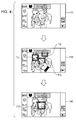
Fig. 4 is a diagram illustrating another screen example when an imaging mode is a pet mode; -
Fig. 5 is a diagram illustrating a setting example of a touch acceptance frame according to an imaging mode; -
Fig. 6 is a diagram illustrating a setting example of a touch acceptance frame according to the size of a subject; -
Fig. 7 is a diagram illustrating a setting example of a touch acceptance frame according to the movement of a subject; -
Fig. 8 is a diagram illustrating a setting example of a touch acceptance frame according to the movement of a subject; -
Fig. 9 is a block diagram illustrating a configuration example of a tracking subject recognition section; -
Fig. 10 is a flow chart describing a process of starting subject tracking; -
Fig. 11 is a flow chart describing a touch acceptance frame setting process; -
Fig. 12 is a diagram describing an example where a tracking subject is recognized according to an imaging mode; and -
Fig. 13 is a block diagram illustrating a configuration example of a computer according to an embodiment of the disclosure. - Below, specific embodiments of the disclosure will be described in detail while referring to the diagrams.
-
Fig. 1 is a block diagram illustrating a configuration example of a digital camera according to an embodiment of the disclosure. - In
Fig. 1 , adigital camera 11 is configured to be provided with alens 12, animaging section 13, adisplay section 14, an external I/F (interface) 15, and animage processing section 16. - The
lens 12 is configured by, for example, a group of a plurality of lenses which provided a zoom function and the like, and light from a subject is concentrated and an image of a subject is produced on an imaging surface of an imaging element of theimaging section 13. Theimaging section 13 is configured by, for example, a CCD (Charge Coupled Device), a CMOS (Complementary Metal Oxide Semiconductor) sensor, or the like, and images the image of the subject and outputs the image obtained via the imaging to theimage processing section 16. - The
display section 14 is configured by an LCD (Liquid Crystal Display), an organic EL (Electro Luminescence) display, or the like, and the image which is imaged in theimaging section 13 and output by imaging processing being carried out in theimage processing section 16, that is, the image where the subject is surrounded by a subject frame, is displayed. The external I/F 15 is configured by a terminal or the like for outputting the image output from theimage processing section 16 to, for example, an external display (not shown). - The
image processing section 16 carries out image processing with regard to the image imaged by theimaging section 13 and outputs the image to thedisplay section 14 and the external I/F 15. Theimage processing section 16 performs image processing where, for example, a subject (for example, a face) which is captured in an image is detected and a subject frame which surrounds a predetermined range of the subject is synthesized in the image. In addition, when an arbitrary subject is selected by a user, theimage processing section 16 performs a subject tracking process where the subject is tracked and performs a process where various types of parameters are adjusted so each is optimal when the subject which is a tracking target (referred to below as tracking subject) is imaged. - The
image processing section 16 is configured to be provided with animage memory 21, amode setting section 22, atouch detection section 23, a subject framesetting processing section 24, a trackingsubject recognition section 25, adetector switching section 26, and a subjecttracking processing section 27. - In the
image memory 21, data of the image imaged by theimaging section 13 is sequentially supplied, and theimage memory 21 sequentially stores the supplied data of the image. - The
mode setting section 22 sets the various types of parameters used in the imaging mode specified by a user. Thedigital camera 11 is provided with, for example, various imaging modes such as a person mode where imaging is performed using imaging conditions which are appropriate for images of people, a pet mode where imaging is performed using imaging conditions which are appropriate for images of animals, and the like. In addition, the imaging mode which is set in themode setting section 22 is referenced in processes which are performed by the subject framesetting processing section 24 and the trackingsubject recognition section 25. - The
touch detection section 23 detects a position (specified position) which is touched when a user touches the screen of thedisplay section 14 based on a signal from a touch panel (not shown) which is installed so as to overlap with the screen of thedisplay section 14. Then, thetouch detection section 23 supplies information showing the touch position to the trackingsubject recognition section 25. - The subject frame
setting processing section 24 has a plurality of detectors which detect a subject captured in an image and performs a subject frame setting process where the size of a subject frame, which surrounds a predetermined range of the subject detected by the detectors, is set. For example, as shown inFig. 1 , the subject framesetting processing section 24 has a face detector 28-1 and an animal detector 28-2 and sets the subject frame with regard to the face of a person detected by the face detector 28-1, the face of an animal detected by the animal detector 28-2, or the like. In addition, the subject frame set by the subject framesetting processing section 24 is synthesized in the image and is displayed in thedisplay section 14. - The tracking
subject recognition section 25 recognizes the tracking subject based on the subject frame set by the subject framesetting processing section 24 when the information showing the touch position touched by a user is supplied from thetouch detection section 23. For example, the trackingsubject recognition section 25 recognizes the subject which is set in the subject frame as the tracking subject if the touch position touched by the user is at an inner side of the subject frame. Then, the trackingsubject recognition section 25 supplies the information where the tracking subject is specified to thedetector switching section 26 in a case where it is possible to recognize the tracking subject. - The
detector switching section 26 recognizes the detector used by the subject framesetting processing section 24 in the detection of the tracking subject via the trackingsubject recognition section 25 when the information specifying the tracking subject is supplied from the trackingsubject recognition section 25. Then, thedetector switching section 26 performs a process of supplying the information specifying the tracking subject to the subjecttracking processing section 27 and switching the detector used by the subjecttracking processing section 27 in the subject tracking process to the detector used in the detection of the tracking subject. - The subject
tracking processing section 27 starts the subject tracking process where the tracking subject which is specified by the information which specifies the tracking subject is tracked using the detector which is switched by thedetector switching section 26. According to this, it is possible for the subjecttracking processing section 27 to execute the subject tracking process using the detector which is appropriate for the tracking subject. - In addition, in the information specifying the tracking subject, for example, information which shows the position of the tracking subject, information which shows color and luminance of the tracking subject, and the like are included. When the data of the next image is stored in the
image memory 21, the subjecttracking processing section 27 detects a region, which has color and luminance close to that of the tracking subject in a predetermined region in the vicinity of the position of the tracking subject specified in the previous image, in the next image and specifies the tracking target. Then, the subjecttracking processing section 27 repeatedly performs specification of the tracking subject from the image sequentially stored in theimage memory 21 based on the position of the tracking subject specified by the image and the color and the luminance of the tracking subject. In this manner, the subject tracking process is performed and the subjecttracking processing section 27 adjusts the various types of parameters so that each is optimal when the tracking subject is imaged. - In this manner, in the
digital camera 11, the subject which has become the tracking target is recognized by the user touching the screen of thedisplay section 14 and the subject tracking process where the subject is tracked is performed. - Here, for example, in a case where a plurality of the subject frames is set with regard to an image where a plurality of subjects is captured, it is not possible for the tracking
subject recognizing section 25 to recognize the tracking subject in a case where the touch position touched by the user is not at an inner side of any of the subject frames. In this case, it is possible for the trackingsubject recognizing section 25 to reference the imaging mode set by themode setting section 22 and recognize the tracking subject. - A process where the tracking
subject recognizing section 25 references the imaging mode and recognizes the tracking subject will be described with reference toFigs. 2 and3 . - Screens P11 to P13 of the
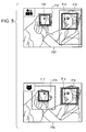
display section 14 when the person mode is set as the imaging mode are shown inFig. 2 , and screens P14 to P16 of thedisplay section 14 when the pet mode is set as the imaging mode are shown inFig. 3 . In addition, in thedigital camera 11, the face detector 28-1 normally operates in the subject framesetting processing section 24. - As shown in
Fig. 2 , in the screens P11 to P13 of thedisplay section 14 when the imaging mode is the person mode, an icon showing a person and "person mode" are displayed. Then, when two children and a dog are imaged as the subject shown in screen P11, the subject framesetting processing section 24 sets the subject frame to the faces of the two children detected by the face detector 28-1. According to this, as shown screen P12, a subject frame F11 and a subject frame F12 set in regard to the faces of the two children are displayed. - Here, the position where the user touches the screen of the
display section 14 is an outer-side vicinity of the subject frame F11 such as the tip of the finger mark shown in screen P12 and is in the vicinity of the dog. In this case, since the imaging mode is the person mode, the trackingsubject recognizing section 25 infers that the subject which the user wants as the tracking target is the person even in an outer side of the subject frame F11, and the face of the child where the subject frame F11 is set is recognized as the tracking subject. According to this, as shown in screen P13, a subject frame F11' for the tracking subject is displayed. The color, size, and the like from the previous subject frame F11 which was recognized as the tracking target is changed and the subject frame F11' for the tracking subject is displayed. - On the other hand, as shown in
Fig. 3 , in screens P14 to P16 of thedisplay section 14 when the imaging mode is the pet mode, an icon showing an animal and "pet mode" are displayed. In screen P14, an image with the same configuration as screen P11 ofFig. 2 is displayed, and as shown in screen P15, a location which is in an outer-side vicinity of the subject frame F11 and in the vicinity of the dog (the same location as in screen P12 ofFig. 2 ) is touched by the user. - In this case, since the imaging mode is the pet mode, the tracking
subject recognizing section 25 infers that the subject which the user wants as the tracking target is the animal and not the children even in an outer side of the subject frame F11 and the dog is recognized as the tracking subject. According to this, as shown in screen P16, a subject frame F13' for the tracking subject which surrounds a predetermined region of the face of the dog is displayed. - Here, when the imaging mode is the pet mode, both the face detector 28-1 and the animal detector 28-2 operate at the same time. In this manner, in a case where the plurality of detectors in the
digital camera 11 operates at the same time, it is possible to display the subject frames with regard to the subjects which are detected by the respective detectors. - That is, as shown in
Fig. 4 , in screen P15' of thedisplay section 14 when the pet mode is set as the imaging mode, it is possible to display the subject frame also on the face of the dog in the same manner as the faces of the children. - However, in order for the tracking
subject recognizing section 25 to determine that the position touched by the user on the screen of thedisplay section 14 is an outer-side vicinity of the subject frame, it is necessary that the region which stipulates the vicinity is determined. As the region, other than setting a wide frame with a constant spacing in a fixed manner with regard to the subject frame, for example, a frame where the spacing changes may be set according to the imaging target, the imaging mode, or the like. In this manner, the frame, where it is acceptable for the subject which is set in the subject frame, to be touched by the user, even when the position where the user touches the screen of thedisplay section 14 is an outer-side of the subject frame, is appropriately referred to below as the touch acceptance frame. - For example, in
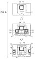
Fig. 5 , screen P17 of thedisplay section 14 when the person mode is set as the imaging mode and screen P18 of thedisplay section 14 when the pet mode is set as the imaging mode are shown. - Screens P17 and P18 are where a person and a dog are imaged and have the same configuration. In addition, in screens P17 and P18, a subject frame F14 with regard to the face of the person and a subject frame F15 with regard to the face of the dog are set as the same locations. In addition, in screens P17 and P18, a touch acceptance frame F16 with regard to the subject frame F14 and a touch acceptance frame F17 with regard to the subject frame F15 are shown with dashed lines. Here, the touch acceptance frames F16 and F17 are diagrammatically shown in order for description and are not shown in the
display section 14. - As shown in screen P17, in the case where the imaging mode is the person mode, since the subject which is prioritized in imaging is the person, the touch acceptance frame F16 where there is the setting of the subject frame F14 of the face of the person which is the subject appropriate to the imaging mode is set to be larger than the touch acceptance frame F17 where there is the setting of subject frame F15 of the face of the dog.
- On the other hand, as shown in screen P18, in the case where the imaging mode is the pet mode, since the subject which is prioritized in imaging is the animal, the touch acceptance frame F17 where there is the setting of the subject frame F15 of the face of the dog which is the subject appropriate to the imaging mode is set to be larger than the touch acceptance frame F16 where there is the setting of subject frame F14 of the face of the person.
- In this manner, by setting the touch acceptance frame with a size according to the imaging mode, it is possible for the
digital camera 11 to estimate the selection intention of the user even if the touch of the user is separated from the subject and to recognize the subject in accordance with the intention as the tracking subject. - In addition, as shown in screen P17, in regard to the person which is the subject, the spacing of the touch acceptance frame F16 with regard to the subject frame F14 is set so that the spacing on the lower side with regard to the subject frame F14 is wider than the spacing on the upper side, right side, and left side with regard to the subject frame F14. This is because, for example, in the case where the subject is the person, the capturing of the body of the person in the lower side of the subject frame (face frame) often occurs. In this manner, by setting the spacing on the lower side of the touch acceptance frame F16 with regard to the subject frame F14 to be wide, it is also possible to set the person as the tracking subject when the body of the person captured in the image is touched.
- In addition, as shown in screen P17, in the case where the subject is the animal, the touch acceptance frame F17 is set so as to have equal spacing with regard to the subject frame F15. In this manner, in the
digital camera 11, the size of the touch acceptance frame according to the type of the subject, specifically, the size of the touch acceptance frame according to the type of detector which detects the subject is set in advance. - Furthermore, the size of the subject frame is adjusted according to the size of the subject captured in the image and the size of the touch acceptance frame is adjusted according to the size of the subject frame.
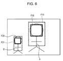
- That is, as shown in
Fig. 6 , in a case where a subject A is captured as so to be larger than a subject B, a subject frame F18 which is set for the subject A is set to be larger than a subject frame F20 which is set for the subject B. In addition, a touch acceptance frame F19 which is set for the subject A is also set to be larger than a touch acceptance frame F21 which is set for the subject B. - In addition, the touch acceptance frame F19 is set so that the spacing (margin) on the lower side of the touch acceptance frame F19 with regard to the subject frame F18 is wider than the spacing on the upper side, right side, and left side, so as to include the body of the subject B. In the same manner, the touch acceptance frame F21 is set so that the spacing on the lower side with regard to the subject frame F20 is wide so as to include the body of the subject B.
- Furthermore, the spacing of the touch acceptance frame with regard to the subject frame may be adjusted, for example, according to the movement of the subject, according to the context (scene) of the subject.
- That is, as shown in
Fig. 7 , when the subject A is captured alone, when movement is detected where the subject B is approaching the subject A from the left side of the subject A, the spacing on the left side of the touch acceptance frame F19 (the subject B side) which is set for the subject A is adjusted so as to become narrower. After that, when movement where the subject B separates from the subject A is detected, the touch acceptance frame F19 is adjusted to return to the original spacing. Here, although not expressed inFig. 7 , the spacing on the subject A side of the touch acceptance frame F21 which is also set for the subject B is adjusted so as to become narrower as the subject B approaches the subject A and is adjusted to return to the original spacing when the subject B separates from the subject A. - In addition, for example, as shown in
Fig. 8 , when the subject A is captured alone, movement where the subject B is approaching the subject A from the left side of the subject A and movement where a subject C is approaching the subject A from the right side of the subject A are detected. In this case, the spacing on both sides of the touch acceptance frame F19 which is set for the subject A is adjusted so as to become narrower. After that, when movement where the subject B and the subject C separate from the subject A is detected, the touch acceptance frame F19 is adjusted to return to the original spacing. Here, the touch acceptance frame F21 which is set for the subject B and a touch acceptance frame F23 which is set for the subject C are adjusted according to the movement of the subject B and the subject C. - As is described with reference to
Figs. 5 to 8 , the touch acceptance frame is set so as to surround a wider range than the subject frame, and the size of the touch acceptance frame is adjusted due to the imaging mode and the imaging scene (the size, type, movement, and the like of the subject). - Next,
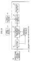
Fig. 9 is a block diagram illustrating a configuration example of the trackingsubject recognition section 25 which sets the touch acceptance frame. - In
Fig. 9 , the trackingsubject recognition section 25 is configured to be provided with astorage section 31, amovement detection section 32, a touch acceptance frame settingprocessing section 33, atouch determination section 34, and arecognition section 35. - In the
storage section 31, information relating to the subject frame set by the subject framesetting processing section 24 is supplied, and information relating to the subject frame is stored in thestorage section 31 for a predetermined period. In the information relating to the subject frame, information which shows the position and the size of the subject frame and information which shows the type of the detector which detects the subject are included. - The
movement detection section 32 detects movement of the subject by determining a change in position of the subject frame in a predetermined period based on the information relating to the subject frame stored in thestorage section 31. - The touch acceptance frame setting
processing section 33 sets the touch acceptance frame with regard to the subject frame based on the imaging mode set by themode setting section 22 and the information relating to the subject frame stored in thestorage section 31. In addition, the touch acceptance frame settingprocessing section 33 adjusts the size of the set touch acceptance frame based on movement of the subject frame which is detected by themovement detection section 32. - When the information which shows the touch position touched by the user is supplied from the
touch detection section 23, thetouch determination section 34 determines whether or not the touch position is in the range of the touch acceptance frame which is set by the touch acceptance frame settingprocessing section 33. Then, in a case where it is determined that the touch position is in the range of the touch acceptance frame, thetouch determination section 34 decides that the subject where the touch acceptance frame is set is the tracking subject and notifies therecognition section 35. - Here, in a case where it is determined that the touch position is not in the range of the touch acceptance frame, the
touch determination section 34 operates the other detectors with regard to the subject framesetting processing section 24. For example, when only the face detector 28-1 is operated, there is a case where the user touches the subject other than the person, for example, the animal. At this time, it is determined that the touch position is not in the range of the touch acceptance frame, but by operating the animal detector 28-2 using the subject framesetting processing section 24, it is possible to detect the animal which is touched by the user and it is possible to recognize the animal as the tracking subject. - The
recognition section 35 recognizes the tracking subject when there is notification of the tracking subject from thetouch determination section 34 and outputs information which specifies the tracking subject. - Next,
Fig. 10 is a flow chart describing a process where thedigital camera 11 starts subject tracking. - For example, the process starts when the
digital camera 11 is activated and the imaging using theimaging section 13 starts, and in step S11, the subject framesetting processing section 24 starts operating the face detector 28-1. Then, the subject framesetting processing section 24 starts the subject frame setting process where the subject frame (face frame) is set with regard to the face of the person which is detected from the image stored in theimage memory 21, and the process progresses to step S12. - In step S12, the
touch detection section 23 determines whether or not the user touches the screen of thedisplay section 14 based on the signal from the touch panel of thedisplay section 14. Then, the process waits until thetouch detection section 23 determines that the user has touched the screen of thedisplay section 14, and when it is determined that the user has touched the screen of thedisplay section 14, the process progresses to step S13. - In step S13, the
touch detection section 23 outputs the information (coordinates) which shows the touch position touched by the user to the trackingsubject recognition section 25 and the trackingsubject recognition section 25 acquires the touch position. - After the process of step S13, the process progresses to step S14, the touch acceptance frame setting process (refer to
Fig. 11 described later) is performed, and the touch acceptance frame is set with regard to the subject frame. After the process of the touch acceptance frame setting process, the process progresses to step S15. - In step S15, in the tracking
subject recognition section 25, thetouch determination section 34 determines whether or not the touch position is in the range of the touch acceptance frame based on the touch position acquired in step S13. - In a case where it is determined in step S15 that the touch position is not in the range (outside of the range) of the touch acceptance frame, the process progresses to step S16, and the
touch determination section 34 determines whether or not all of the detectors of the subject framesetting processing section 24 are operating. - In a case where it is determined in step S16 that not all of the detectors of the subject frame
setting processing section 24 are operating, the process progresses to step S17. - In step S17, the
touch determination section 34 requests operation of the detectors other than the detectors which are operating with regard to the subject framesetting processing sector 24. In accordance with this, the subject framesetting processing section 24 starts the operation of the other detectors, the process returns to step S14, and below, the process is repeated in the same manner. That is, the detection of the subject using the detectors which have begun operating is performed, the subject frame is set when the subject is newly detected, and the touch acceptance frame is newly set with regard to the subject frame. - On the other hand, in a case where it is determined in step S16 that all of the detectors of the subject frame
setting processing section 24 are operating, the process returns to step S12, and below, the process is repeated in the same manner. That is, in this case, it is not possible for the tracking subject to be recognized with regard to the touch of the user, and the detection of a new touch is awaited. Here, in this case, that it was not possible to recognize the tracking subject may be displayed on thedisplay section 14. - On the other hand, in a case where it is determined in step S15 that the touch position is in the range of the touch acceptance frame, the process progresses to step S18.
- In step S18, the
recognition section 35 recognizes the subject, which is set in the touch acceptance frame in which the touch position is in the range, as the tracking subject and acquires the color and luminance in the subject frame set for the subject. Then, therecognition section 35 supplies information, which includes information which shows the position of the tracking subject, and information which shows the color and the luminance of the tracking subject and the like and which specifies the tracking subject, to thedetector switching section 26. - After the process of step S18, the process progresses to step S19, the
detector switching section 26 performs a process of recognizing the detector which detects the tracking subject and switching the detector with regard to the subjecttracking processing section 27 so as to use the detector in the subject tracking process. In addition, thedetector switching section 26 supplies the information which specifies the tracking subject to the subjecttracking processing section 27 and the process progresses to step S20. - In step S20, the subject
tracking processing section 27 uses the detector switched in step S18 and the subject tracking process where the tracking subject is tracked starts based on the information which specifies the tracking subject. After the process of step S20, the process returns to step S12, the process waits until the user touches the next subject, and below, the process is repeated in the same manner. - As above, in the
digital camera 11, when the region in an inner side of the touch acceptance frame is touched, since the subject which is set in the touch acceptance frame is recognized as the tracking subject, it is possible for the subject to be recognized with precision even when the touch position of the user is outside of the subject frame. - In addition, in the case where the position touched by the user is outside of the range of the touch acceptance frame, by operating the other detectors, it is possible to detect the subject even when the detector for detecting the subject which the user wants as the tracking target is not operating. According to this, when setting the subject which is the tracking target, it is possible to improve the convenience of use for the user.
- That is, in the case where the imaging mode is the person mode and only the face detector 28-1 is operating, when the user touches the animal which is displayed in the
display section 14, the operation of the animal detector 28-2 automatically starts and the animal is recognized as the tracking subject. In this manner, it is no bother for the user to change the imaging mode to the animal mode and it is possible to start the subject tracking process with the animal as the tracking subject. - In addition, when the plurality of detectors is operated, the tracking subject is recognized, and the subject tracking process is started in this manner, it is possible for the
detector switching section 26 to stop the operation of the detectors other than the detector used in the detection of the tracking subject. According to this, it is possible to reduce the processing which is executed in theimage processing section 16, and for example, it is possible to suppress the use of power. - Next,
Fig. 11 is a flow chart describing the touch acceptance frame setting process of step S14 ofFig. 10 . - In step S31, the touch acceptance frame setting
processing section 33 reads out and acquires the information, which relates to the subject frame displayed in thedisplay section 14 at a timing when thetouch determination section 34 acquires the touch position, from thestorage section 31. - After the process of step S31, the process progresses to step S32, the touch acceptance frame setting
processing section 33 references themode setting section 22, the imaging mode which is currently set is acquired, and the process progresses to step S33. - In step S33, the touch acceptance frame setting
processing section 33 recognizes the type of the subject where the subject frame is set based on the information relating to the subject frame acquired in step S31. Then, the touch acceptance frame settingprocessing section 33 sets the touch acceptance frame with regard to the subject frame in a size which is a standard registered in advance based on the type of the recognized subject and the imaging mode acquired in step S32. - Here, in the touch acceptance frame setting
processing section 33, the size, which is the standard of the touch acceptance frame with regard to the size of the subject frame, is registered in advance. In addition, the size of the touch acceptance frame with regard to the subject frame differs in accordance with the type of the subject for each of the imaging modes as described with reference toFig. 5 , and in the touch acceptance frame settingprocessing section 33, the size, which is the standard of the touch acceptance frame with regard to the subject frame, is registered for each of the imaging modes. - After the process of step S33, the process progresses to step S34, the touch acceptance frame setting
processing section 33 references themovement detection section 32 and acquires the movement of the subject, and in step S35, it is determined whether or not it is necessary to adjust the touch acceptance frame set to the size which is the standard. - As described with reference to
Figs. 7 and8 above, in the case where movement is detected where subjects approach each other, the touch acceptance frames are adjusted so that the spacing of the touch acceptance frames with regard to the subject frame on the opposing sides of each of the subjects become narrower. In addition, in the case where movement is detected where subjects which are close to each other separate, the touch acceptance frame is adjusted so that the narrowed spacing is widened. Accordingly, the touch acceptance frame settingprocessing section 33 determines whether it is necessary to adjust the touch acceptance frame in the case where movement of the subjects is detected in this manner. - In a case where it is determined in step S35 that it is necessary to adjust the touch acceptance frame, the process progresses to step S36, the touch acceptance frame setting
processing section 33 adjusts the touch acceptance frame according to movement of the subject, and the process is completed. - On the other hand, in a case where it is determined in step S35 that it is not necessary to adjust the touch acceptance frame, the process skips step S36 and is completed.
- As above, since the touch acceptance frame setting
processing section 33 sets the size of the touch acceptance frame according to the imaging mode, it is possible for the subject which is prioritized and imaged in each of the imaging modes to be recognized as the tracking subject with priority. - In addition, the touch acceptance frame setting
processing section 33 adjusts the touch acceptance frame according to the imaging scene (that is, the context of the imaged image), more specifically, according to characteristics of the subject captured in the image (type, size, and the like), movement of the subject relative to each other, or the like. According to this, it is possible to recognize the subject which is appropriate for each of the imaging scenes as the tracking subject with priority. - In this manner, since the appropriate touch acceptance frame is set based on the imaging mode and the imaging scene, it is possible to recognize the subject which the user wants as the tracking target with precision.
- In addition, in a case where the subjects move, there are cases where the position which the user touches and the position where the subject is captured do not match, and there are cases where the subject, which differs from the intention of the user, is recognized as the tracking subject and the subject tracking process is performed. With regard to this, in the
digital camera 11, since the range of the touch acceptance frame changes according to the movement of the subject, it is possible to avoid the subject which differs from the intention of the user being recognized as the tracking subject and touching is not repeated a plurality of times in order for the user to select the correct subject. That is, since it is possible for the subject to be selected with precision using a simple operation, it is possible to reduce the burden on the user. - Here, it is possible for the
digital camera 11 to be provided with the imaging mode other than the person mode and the pet mode described above, and for the subject framesetting processing section 24 and the trackingsubject recognition section 25 to set the subject frame and the touch acceptance frame for the subject which is prioritized in imaging for each of the imaging modes. For example, thedigital camera 11 is provided with a child prioritizing mode which performs imaging with imaging conditions which are appropriate for imaging children, an adult prioritizing mode which performs imaging with imaging conditions which are appropriate for imaging adults, or the like. - Screen P19 of the
display section 14 when the child prioritizing mode is set as the imaging mode and screen P20 of thedisplay section 14 when the adult prioritizing mode is set as the imaging mode are shown inFig. 12 . - Screens P19 and P20 have the same configuration where two children and one adult are captured, subject frames F24 and F25 are displayed for the faces of the children and a subject frame F26 is displayed for the face of the adult. With regard to screens P19 and P20 such as these, there is a case where the position where the user touches the screen of the
display section 14 is between the subject frames F25 and F26 in the same manner as the tip of the finger mark shown in screens P19 and P20. - In this case, if the imaging mode is the child prioritizing mode, the child which is set with the subject frame F25 is recognized as the tracking subject, and if the imaging mode is the adult prioritizing mode, the adult which is set with the subject frame F26 is recognized as the tracking subject. In this manner, in the
digital camera 11, it is possible for the intention of the user to be estimated by referencing the imaging mode even when the touch position of the user is between the subject frames F25 and F26 and for the tracking subject to be recognized with precision. - In addition, the
digital camera 11 is provided with the imaging modes such as an underwater mode, a food mode, a flower mode, or the like, the subject frame is set with regard to the subject that is appropriate for each of the imaging modes, and the touch acceptance frame is adjusted. That is, other than the face detector 28-1 and the animal detector 28-2 shown inFig. 1 , it is possible for the subject framesetting processing section 24 to be provided with a fish detector, a food detector, a flower detector, or the like. As the animal detector 28-2, there may be a dog face detector and a cat face detector. In addition, thedigital camera 11 may be provided with a scenery mode, a night scene mode, or the like as the imaging mode. - Here, other than being set by the user operating the
digital camera 11, it is possible for the imaging modes to be automatically set so as to perform optimal imaging according to the imaging context by analyzing the image in thedigital camera 11. - In addition, in the embodiment, it is described that the face detector 28-1 is normally operating, but there may be a state where the detector is not normally operating in this manner and the subject frame is not displayed on the
display section 14 before being touched by the user. That is, the operation of the detectors may be started at a timing when there is a touch by the user. - Here, in the embodiment, the subject to be tracked is selected by the user touching the screen of the
display section 14, but the subject may be selected by another means, for example, by operation of operation keys. In addition, the subject may be selected by using a guide frame for matching the subject with the angle of view in advance. - Here, other than the digital camera such as a digital still camera, a digital video camera, or the like, it is possible to apply the disclosure to a device which is provided with an imaging function such as a mobile phone device, a personal computer, or the like.
- It is possible for the series of processes described above to be executed by using hardware and is possible for the series of processes described above to be executed by using software. In a case where the series of processes is executing using software, a program which configures the software is installed from a program recording medium to a computer which has specialized hardware built in, or by installing each type of program, to, for example, a generalized personal computer which is able to execute each type of function.
-
Fig. 13 is a block diagram illustrating a configuration example of hardware of a computer which executes the series of processes described above using a program. - In the computer, a CPU (Central Processing Unit) 101, ROM (Read Only Memory) 102, and a RAM (Random Access Memory) 103 are connected to each other by a
bus 104. - In the
bus 104, an input andoutput interface 105 is further connected. In the input andoutput interface 105, aninput section 106 formed by a keyboard, a mouse, a microphone, or the like, anoutput section 107 formed by a display, a speaker, or the like, astorage section 108 formed by a hard disk, a nonvolatile memory, or the like, acommunication section 109 formed by a network interface or the like, adrive 110 which drives a magnetic disk, an optical disc, a magneto-optical disc, or aremovable medium 111 such as a semiconductor memory or the like, are connected. - In the computer configured as above, the
CPU 101 performs the series of processes described above by, for example, executing the loading of the program stored in thestorage section 108 in theRAM 103 via the input andoutput interface 105 and thebus 104. - The program executed by the computer (CPU 101) is, for example, recorded in a magnetic disk (including a flexible disk), an optical disc (a CD-ROM (Compact Disc-Read Only Memory), a DVD (Digital Versatile Disc), or the like), a magneto-optical disc, or the
removable medium 111 formed by a semiconductor memory or the like such as a package medium, or is provided via a wired or wireless transmission medium such as a local area network, the internet, or digital satellite broadcasting. - Then, it is possible to install the program in the
storage section 108 via the input andoutput interface 105 by mounting theremovable medium 111 in thedrive 110. In addition, it is possible to receive the program using thecommunication section 109 via the wired or wireless transmission medium and install the program in thestorage section 108. Alternatively, it is possible to have the program installed in advance in theROM 102 or thestorage medium 108. - Here, the program executed by the computer may be a program which performs the processes in a time series in the sequence described in the specifications or may be a program which performs the processes in parallel or at a necessary timing such as when a request is performed. In addition, the program may be processed using one CPU or may be distributed and processed using a plurality of CPUs.
- The present disclosure contains subject matter related to that disclosed in Japanese Priority Patent Application
JP 2010-151951 - It should be understood by those skilled in the art that various modifications, combinations, sub-combinations and alterations may occur depending on design requirements and other factors insofar as they are within the scope of the appended claims or the equivalents thereof.
Claims (10)
- An image processing device comprising:a subject frame setting section which, by operating a subject detector which detects a subject captured in an image, sets a subject frame which surrounds a predetermined range of the subject detected from the image;an acceptance frame setting section which sets an acceptance frame with a range wider than the subject frame according to the context of the image;a position detecting section which detects a specified position on an image which is specified by a user; anda recognizing section which recognizes a subject which is a tracking target based on the acceptance frame set by the acceptance frame setting section and the specified position detected by the position detecting section.
- The image processing device according to Claim 1, wherein the subject frame setting section has a plurality of subject detectors which are able to respectively detect a plurality of types of the subjects, and in a case where it is unable to recognize the subject which is the tracking target using the recognition section, the operation of the subject detectors other than the subject detector which was operating are started and other types of the subjects are detected.
- The image processing device according to Claim 1 or 2,
wherein the acceptance frame setting section sets the size of the acceptance frame with regard to the subject frame according to the size of the subject which is captured in the image. - The image processing device according to any one of Claims 1 to 3,
wherein the acceptance frame setting section sets the spacing of the acceptance frame with regard to the subject frame according to the type of the subject which is captured in the image. - The image processing device according to any one of Claims 1 to 4,
wherein the acceptance frame setting section adjusts the spacing of the acceptance frame with regard to the subject frame according to the movement of the subject which is captured in the image. - An image processing method comprising:setting, by operating a subject detector which detects a subject captured in an image, a subject frame which surrounds a predetermined range of the subject detected from the image;setting an acceptance frame with a range wider than the subject frame according to the context of the image;detecting a specified position on an image which is specified by a user; andrecognizing a subject which is a tracking target based on the acceptance frame and the specified position.
- An image processing device comprising:a subject frame setting section which, by operating a subject detector which detects a subject captured in an image, sets a subject frame which surrounds a predetermined range of the subject detected from the image;an acceptance frame setting section which sets an acceptance frame with a range wider than the subject frame according to an imaging mode set for performing imaging using imaging conditions which are appropriate for a certain image;a position detecting section which detects a specified position on an image which is specified by a user; anda recognizing section which recognizes a subject which is a tracking target based on the acceptance frame set by the acceptance frame setting section and the specified position detected by the position detecting section.
- The image processing device according to Claim 7, wherein the subject frame setting section has a plurality of subject detectors which are able to respectively detect a plurality of types of the subjects, and in a case where it is unable to recognize the subject which is the tracking target using the recognition section, the operation of the subject detectors other than the subject detector which were operating is started and other types of the subjects are detected.
- The image processing device according to Claim 7 or 8,
wherein the acceptance frame setting section sets the acceptance frame of the subject which is appropriate for the imaging mode which is currently set to be larger than the acceptance frame of the subject which is not appropriate for the imaging mode when a plurality of types of the subject is captured in the image. - An image processing method comprising:setting, by operating a subject detector which detects a subject captured in an image, a subject frame which surrounds a predetermined range of the subject detected from the image;setting an acceptance frame with a range wider than the subject frame according to an imaging mode set for performing imaging using imaging conditions which are appropriate for a certain image;detecting a specified position on an image which is specified by a user; andrecognizes a subject which is a tracking target based on the acceptance frame and the specified position.
Applications Claiming Priority (1)
| Application Number | Priority Date | Filing Date | Title |
|---|---|---|---|
| JP2010151951A JP2012015889A (en) | 2010-07-02 | 2010-07-02 | Image processing device and image processing method |
Publications (2)
| Publication Number | Publication Date |
|---|---|
| EP2402884A2 true EP2402884A2 (en) | 2012-01-04 |
| EP2402884A3 EP2402884A3 (en) | 2017-03-29 |
Family
ID=45002172
Family Applications (1)
| Application Number | Title | Priority Date | Filing Date |
|---|---|---|---|
| EP11167246.5A Withdrawn EP2402884A3 (en) | 2010-07-02 | 2011-05-24 | Image processing device and image processing method |
Country Status (4)
| Country | Link |
|---|---|
| US (3) | US8643740B2 (en) |
| EP (1) | EP2402884A3 (en) |
| JP (1) | JP2012015889A (en) |
| CN (1) | CN102316263B (en) |
Cited By (3)
| Publication number | Priority date | Publication date | Assignee | Title |
|---|---|---|---|---|
| US10140257B2 (en) | 2013-08-02 | 2018-11-27 | Symbol Technologies, Llc | Method and apparatus for capturing and processing content from context sensitive documents on a mobile device |
| US10769362B2 (en) | 2013-08-02 | 2020-09-08 | Symbol Technologies, Llc | Method and apparatus for capturing and extracting content from documents on a mobile device |
| CN114663491A (en) * | 2020-12-08 | 2022-06-24 | 北京外号信息技术有限公司 | Method and system for providing information to a user in a scene |
Families Citing this family (27)
| Publication number | Priority date | Publication date | Assignee | Title |
|---|---|---|---|---|
| JP5485712B2 (en) * | 2010-01-07 | 2014-05-07 | 株式会社ザクティ | Electronic camera |
| JP5136669B2 (en) * | 2011-03-18 | 2013-02-06 | カシオ計算機株式会社 | Image processing apparatus, image processing method, and program |
| BR112014007538B1 (en) * | 2011-09-30 | 2020-06-02 | Hewlett-Packard Development Company, L.P. | AUTHENTICATION SYSTEM AND INK CARTRIDGE |
| JP5640175B2 (en) * | 2012-03-16 | 2014-12-10 | 富士フイルム株式会社 | Image display apparatus, photographing apparatus equipped with the image display apparatus as a finder apparatus, and image display method |
| JPWO2013161250A1 (en) * | 2012-04-26 | 2015-12-21 | パナソニックIpマネジメント株式会社 | Strobe device and imaging device including the same |
| JP5854280B2 (en) * | 2012-10-03 | 2016-02-09 | ソニー株式会社 | Information processing apparatus, information processing method, and program |
| CN103813075A (en) * | 2012-11-07 | 2014-05-21 | 联想(北京)有限公司 | Reminding method and electronic device |
| EP2963909A4 (en) * | 2013-02-28 | 2016-10-19 | Nikon Corp | Electronic apparatus |
| WO2014142468A1 (en) | 2013-03-13 | 2014-09-18 | Samsung Electronics Co., Ltd. | Method of providing copy image and ultrasound apparatus therefor |
| US11096668B2 (en) | 2013-03-13 | 2021-08-24 | Samsung Electronics Co., Ltd. | Method and ultrasound apparatus for displaying an object |
| JP6701512B2 (en) | 2013-09-24 | 2020-05-27 | ソニー株式会社 | Imaging device, imaging method, and program |
| JP6719899B2 (en) * | 2015-12-16 | 2020-07-08 | キヤノン株式会社 | Imaging device, control method thereof, and control program |
| JP6702746B2 (en) * | 2016-02-10 | 2020-06-03 | キヤノン株式会社 | Imaging device, control method thereof, program, and storage medium |
| JP7174894B2 (en) * | 2016-03-28 | 2022-11-18 | パナソニックIpマネジメント株式会社 | Video processing device, video processing system, video processing method, and video output device |
| JP6942464B2 (en) * | 2016-12-09 | 2021-09-29 | キヤノン株式会社 | Image processing equipment, image processing methods, and programs |
| US11431893B2 (en) | 2018-10-18 | 2022-08-30 | Panasonic Intellectual Property Management Co., Ltd. | Imaging apparatus |
| JP2020136899A (en) | 2019-02-19 | 2020-08-31 | ソニーセミコンダクタソリューションズ株式会社 | Imaging equipment, electronic devices, and imaging methods |
| CN109981982B (en) * | 2019-03-25 | 2021-02-19 | 联想(北京)有限公司 | Control method, device and system |
| TWI706335B (en) * | 2019-10-17 | 2020-10-01 | 國立交通大學 | Object characteristic locating device and laser and imaging integration system |
| CN112348077B (en) * | 2020-11-04 | 2025-10-31 | 深圳Tcl新技术有限公司 | Image recognition method, device, equipment and computer readable storage medium |
| JP7743189B2 (en) | 2021-02-24 | 2025-09-24 | キヤノン株式会社 | Image processing device and control method thereof, and imaging device |
| JP7657611B2 (en) | 2021-02-26 | 2025-04-07 | キヤノン株式会社 | Image processing device and control method thereof, imaging device, and program |
| JP2022131706A (en) | 2021-02-26 | 2022-09-07 | キヤノン株式会社 | IMAGE PROCESSING DEVICE AND CONTROL METHOD THEREOF, IMAGING DEVICE, AND PROGRAM |
| CN112926479A (en) * | 2021-03-08 | 2021-06-08 | 新疆爱华盈通信息技术有限公司 | Cat face identification method and system, electronic device and storage medium |
| TWI815590B (en) * | 2022-08-04 | 2023-09-11 | 和碩聯合科技股份有限公司 | Treadmill and speed control method thereof |
| KR20240066796A (en) * | 2022-11-08 | 2024-05-16 | 삼성전자주식회사 | Electronic device and Method for controlling the electronic device thereof |
| JP2024169176A (en) * | 2023-05-25 | 2024-12-05 | キヤノン株式会社 | Imaging device, control method and program thereof |
Citations (3)
| Publication number | Priority date | Publication date | Assignee | Title |
|---|---|---|---|---|
| JP2006101186A (en) | 2004-09-29 | 2006-04-13 | Nikon Corp | camera |
| US20080181460A1 (en) * | 2007-01-31 | 2008-07-31 | Masaya Tamaru | Imaging apparatus and imaging method |
| JP2010151951A (en) | 2008-12-24 | 2010-07-08 | Mitsubishi Electric Engineering Co Ltd | Specific direction image display system |
Family Cites Families (4)
| Publication number | Priority date | Publication date | Assignee | Title |
|---|---|---|---|---|
| JP4457358B2 (en) * | 2006-05-12 | 2010-04-28 | 富士フイルム株式会社 | Display method of face detection frame, display method of character information, and imaging apparatus |
| JP2009010777A (en) * | 2007-06-28 | 2009-01-15 | Sony Corp | Imaging apparatus, imaging control method, program |
| JP5039786B2 (en) * | 2007-07-23 | 2012-10-03 | パナソニック株式会社 | Imaging device |
| JP2010011441A (en) * | 2008-05-26 | 2010-01-14 | Sanyo Electric Co Ltd | Imaging apparatus and image playback device |
-
2010
- 2010-07-02 JP JP2010151951A patent/JP2012015889A/en not_active Withdrawn
-
2011
- 2011-05-17 US US13/109,281 patent/US8643740B2/en not_active Expired - Fee Related
- 2011-05-24 EP EP11167246.5A patent/EP2402884A3/en not_active Withdrawn
- 2011-06-24 CN CN201110171591.5A patent/CN102316263B/en not_active Expired - Fee Related
-
2013
- 2013-10-02 US US14/043,964 patent/US8947553B2/en active Active
-
2014
- 2014-12-01 US US14/556,685 patent/US9311712B2/en active Active
Patent Citations (3)
| Publication number | Priority date | Publication date | Assignee | Title |
|---|---|---|---|---|
| JP2006101186A (en) | 2004-09-29 | 2006-04-13 | Nikon Corp | camera |
| US20080181460A1 (en) * | 2007-01-31 | 2008-07-31 | Masaya Tamaru | Imaging apparatus and imaging method |
| JP2010151951A (en) | 2008-12-24 | 2010-07-08 | Mitsubishi Electric Engineering Co Ltd | Specific direction image display system |
Cited By (3)
| Publication number | Priority date | Publication date | Assignee | Title |
|---|---|---|---|---|
| US10140257B2 (en) | 2013-08-02 | 2018-11-27 | Symbol Technologies, Llc | Method and apparatus for capturing and processing content from context sensitive documents on a mobile device |
| US10769362B2 (en) | 2013-08-02 | 2020-09-08 | Symbol Technologies, Llc | Method and apparatus for capturing and extracting content from documents on a mobile device |
| CN114663491A (en) * | 2020-12-08 | 2022-06-24 | 北京外号信息技术有限公司 | Method and system for providing information to a user in a scene |
Also Published As
| Publication number | Publication date |
|---|---|
| US20150085139A1 (en) | 2015-03-26 |
| US20120002067A1 (en) | 2012-01-05 |
| US9311712B2 (en) | 2016-04-12 |
| CN102316263B (en) | 2016-08-24 |
| JP2012015889A (en) | 2012-01-19 |
| US8947553B2 (en) | 2015-02-03 |
| US8643740B2 (en) | 2014-02-04 |
| US20140029799A1 (en) | 2014-01-30 |
| CN102316263A (en) | 2012-01-11 |
| EP2402884A3 (en) | 2017-03-29 |
Similar Documents
| Publication | Publication Date | Title |
|---|---|---|
| US9311712B2 (en) | Image processing device and image processing method | |
| US11012614B2 (en) | Image processing device, image processing method, and program | |
| JP5159515B2 (en) | Image processing apparatus and control method thereof | |
| JP5136669B2 (en) | Image processing apparatus, image processing method, and program | |
| US8654243B2 (en) | Image pickup apparatus and control method thereof | |
| US9075459B2 (en) | Imaging apparatus, imaging method, and computer-readable storage medium providing a touch panel display user interface | |
| US8659681B2 (en) | Method and apparatus for controlling zoom using touch screen | |
| CN103858043B (en) | Picture pick-up device and its control method | |
| US10630891B2 (en) | Image processing apparatus, image processing method, and program | |
| US20110063491A1 (en) | Digital photographing apparatus and method of controlling the same | |
| US8648960B2 (en) | Digital photographing apparatus and control method thereof | |
| KR101605771B1 (en) | Digital photographing apparatus, method for controlling the same, and recording medium storing program to execute the method | |
| US11496670B2 (en) | Electronic device with display screen capable of reliable detection of a user selected displayed eye region in a scene to be captured, and region selection method | |
| US10958825B2 (en) | Electronic apparatus and method for controlling the same | |
| JPWO2020129620A1 (en) | Imaging control device, imaging device, imaging control method | |
| JP5370555B2 (en) | Imaging apparatus, imaging method, and program | |
| JP2015114880A (en) | Display device with touch panel | |
| US12288312B2 (en) | Image processing apparatus, image processing method, imaging apparatus, and storage medium for capturing images having different focus positions | |
| JP2026027693A (en) | Image processing device, control method for image processing device, and program | |
| KR20100101914A (en) | Method and apparatus for processing image signal |
Legal Events
| Date | Code | Title | Description |
|---|---|---|---|
| 17P | Request for examination filed |
Effective date: 20110524 |
|
| AK | Designated contracting states |
Kind code of ref document: A2 Designated state(s): AL AT BE BG CH CY CZ DE DK EE ES FI FR GB GR HR HU IE IS IT LI LT LU LV MC MK MT NL NO PL PT RO RS SE SI SK SM TR |
|
| AX | Request for extension of the european patent |
Extension state: BA ME |
|
| PUAI | Public reference made under article 153(3) epc to a published international application that has entered the european phase |
Free format text: ORIGINAL CODE: 0009012 |
|
| PUAL | Search report despatched |
Free format text: ORIGINAL CODE: 0009013 |
|
| AK | Designated contracting states |
Kind code of ref document: A3 Designated state(s): AL AT BE BG CH CY CZ DE DK EE ES FI FR GB GR HR HU IE IS IT LI LT LU LV MC MK MT NL NO PL PT RO RS SE SI SK SM TR |
|
| AX | Request for extension of the european patent |
Extension state: BA ME |
|
| RIC1 | Information provided on ipc code assigned before grant |
Ipc: G06K 9/20 20060101AFI20170221BHEP Ipc: G06K 9/32 20060101ALI20170221BHEP Ipc: H04N 5/232 20060101ALI20170221BHEP |
|
| STAA | Information on the status of an ep patent application or granted ep patent |
Free format text: STATUS: EXAMINATION IS IN PROGRESS |
|
| 17Q | First examination report despatched |
Effective date: 20191018 |
|
| GRAP | Despatch of communication of intention to grant a patent |
Free format text: ORIGINAL CODE: EPIDOSNIGR1 |
|
| STAA | Information on the status of an ep patent application or granted ep patent |
Free format text: STATUS: GRANT OF PATENT IS INTENDED |
|
| RIC1 | Information provided on ipc code assigned before grant |
Ipc: G06K 9/32 20060101ALI20201217BHEP Ipc: H04N 5/232 20060101ALI20201217BHEP Ipc: G06K 9/20 20060101ALI20201217BHEP Ipc: G06K 9/00 20060101ALI20201217BHEP Ipc: G06T 7/73 20170101AFI20201217BHEP |
|
| INTG | Intention to grant announced |
Effective date: 20210115 |
|
| RAP3 | Party data changed (applicant data changed or rights of an application transferred) |
Owner name: SONY GROUP CORPORATION |
|
| STAA | Information on the status of an ep patent application or granted ep patent |
Free format text: STATUS: THE APPLICATION IS DEEMED TO BE WITHDRAWN |
|
| 18D | Application deemed to be withdrawn |
Effective date: 20210526 |