EP2402696A1 - Flow module, reactor or heat exchanger plate clamping device - Google Patents
Flow module, reactor or heat exchanger plate clamping device Download PDFInfo
- Publication number
- EP2402696A1 EP2402696A1 EP10168219A EP10168219A EP2402696A1 EP 2402696 A1 EP2402696 A1 EP 2402696A1 EP 10168219 A EP10168219 A EP 10168219A EP 10168219 A EP10168219 A EP 10168219A EP 2402696 A1 EP2402696 A1 EP 2402696A1
- Authority
- EP
- European Patent Office
- Prior art keywords
- reactor
- clamping device
- heat exchanger
- flow module
- exchanger plate
- Prior art date
- Legal status (The legal status is an assumption and is not a legal conclusion. Google has not performed a legal analysis and makes no representation as to the accuracy of the status listed.)
- Withdrawn
Links
- 238000010276 construction Methods 0.000 abstract description 5
- 238000012986 modification Methods 0.000 description 1
- 230000004048 modification Effects 0.000 description 1
- 238000007789 sealing Methods 0.000 description 1
Images


Classifications
-
- F—MECHANICAL ENGINEERING; LIGHTING; HEATING; WEAPONS; BLASTING
- F28—HEAT EXCHANGE IN GENERAL
- F28F—DETAILS OF HEAT-EXCHANGE AND HEAT-TRANSFER APPARATUS, OF GENERAL APPLICATION
- F28F3/00—Plate-like or laminated elements; Assemblies of plate-like or laminated elements
- F28F3/08—Elements constructed for building-up into stacks, e.g. capable of being taken apart for cleaning
- F28F3/083—Elements constructed for building-up into stacks, e.g. capable of being taken apart for cleaning capable of being taken apart
-
- F—MECHANICAL ENGINEERING; LIGHTING; HEATING; WEAPONS; BLASTING
- F28—HEAT EXCHANGE IN GENERAL
- F28D—HEAT-EXCHANGE APPARATUS, NOT PROVIDED FOR IN ANOTHER SUBCLASS, IN WHICH THE HEAT-EXCHANGE MEDIA DO NOT COME INTO DIRECT CONTACT
- F28D9/00—Heat-exchange apparatus having stationary plate-like or laminated conduit assemblies for both heat-exchange media, the media being in contact with different sides of a conduit wall
- F28D9/0031—Heat-exchange apparatus having stationary plate-like or laminated conduit assemblies for both heat-exchange media, the media being in contact with different sides of a conduit wall the conduits for one heat-exchange medium being formed by paired plates touching each other
- F28D9/0043—Heat-exchange apparatus having stationary plate-like or laminated conduit assemblies for both heat-exchange media, the media being in contact with different sides of a conduit wall the conduits for one heat-exchange medium being formed by paired plates touching each other the plates having openings therein for circulation of at least one heat-exchange medium from one conduit to another
- F28D9/005—Heat-exchange apparatus having stationary plate-like or laminated conduit assemblies for both heat-exchange media, the media being in contact with different sides of a conduit wall the conduits for one heat-exchange medium being formed by paired plates touching each other the plates having openings therein for circulation of at least one heat-exchange medium from one conduit to another the plates having openings therein for both heat-exchange media
-
- F—MECHANICAL ENGINEERING; LIGHTING; HEATING; WEAPONS; BLASTING
- F28—HEAT EXCHANGE IN GENERAL
- F28F—DETAILS OF HEAT-EXCHANGE AND HEAT-TRANSFER APPARATUS, OF GENERAL APPLICATION
- F28F9/00—Casings; Header boxes; Auxiliary supports for elements; Auxiliary members within casings
- F28F9/007—Auxiliary supports for elements
- F28F9/0075—Supports for plates or plate assemblies
-
- F—MECHANICAL ENGINEERING; LIGHTING; HEATING; WEAPONS; BLASTING
- F28—HEAT EXCHANGE IN GENERAL
- F28F—DETAILS OF HEAT-EXCHANGE AND HEAT-TRANSFER APPARATUS, OF GENERAL APPLICATION
- F28F2225/00—Reinforcing means
- F28F2225/02—Reinforcing means for casings
-
- F—MECHANICAL ENGINEERING; LIGHTING; HEATING; WEAPONS; BLASTING
- F28—HEAT EXCHANGE IN GENERAL
- F28F—DETAILS OF HEAT-EXCHANGE AND HEAT-TRANSFER APPARATUS, OF GENERAL APPLICATION
- F28F2225/00—Reinforcing means
- F28F2225/08—Reinforcing means for header boxes
Definitions
- the present invention relates to a flow module, reactor or heat exchanger plate clamping device.
- the present invention provides a solution that reduces the disadvantages of the above mentioned problems, namely the limitation and distribution of the load.
- the flow module, reactor or heat exchanger plate clamping device comprises two U-section formed end plates, springs, and tensioning rods, wherein at least one end plate comprises, an elongated beam flange and on each side of said beam flange a beam web, where the long sides of the beam webs each has a groove in which the beam flange is fitted, in such a way that an end plate with a U-section is formed.
- edge of the long side of the beam flange (3) is stepped, in such a way that it comprises a tongue which is fitted in the groove of the beam web.
- the grooves have bridges, which bridges correspond to interruptions in the flanges.
- Fig. 1 discloses a side view of a closed reactor frame 1 holding reactor or flow module plates 6 in place.
- distribution plates 15 and pressure plates 13 are placed on each side of the stack of reactor or flow module plates 6.
- the stack of reactor or flow module plates 6 are pressed and held together by a pressure applied by two end plates 2, one on each side of the stack 6 outside the distribution plates 15 which the end plates 2 are pressed together by tensioning rods 7 applied in holes in the end plates 2, which rods are tightened evenly to press the stack 6 together into sealing contact with each other.
- each end plate 2 comprises an elongated beam flange 3 and a likewise elongated beam web 4 arranged on each side of said beam flange 3 thus forming a U-shape beam construction.
- Each beam web 4 has a groove 5 along an edge of its long side 8. The edges of the long side of the beam flanges 3 are fitted in the groove 5.
- bolts 9 are arranged in through holes along the edge of the web 4 fastened in corresponding holes in the flange 3.
- the edge of the long side of the beam flange 3 may be stepped, i.e. the edge has a tongue 10 of about half the thickness of the edge.
- this tongue 10 is fitted into the groove 5 of the beam webs 4.
- the grooves 5 may have bridges 12 i.e. interruptions in a groove 5 at strategic positions, which bridges 12 correspond to interruptions in the flanges 10 at the same positions.
- a clamping device may also be used with plate heat exchangers and other flow modules comprising plates.
Landscapes
- Engineering & Computer Science (AREA)
- Physics & Mathematics (AREA)
- Thermal Sciences (AREA)
- Mechanical Engineering (AREA)
- General Engineering & Computer Science (AREA)
- Heat-Exchange Devices With Radiators And Conduit Assemblies (AREA)
Abstract
A flow module, reactor or heat exchanger plate clamping device comprises two U-section formed end plates 2, springs 11, and tensioning rods 7, wherein at least one end plate 2 comprises, an elongated beam flange 3 and on each side of said beam flange 3 a beam web 4, where the long sides 8 of the beam webs 4 each has a groove 5 in which the beam flange 3 is fitted, in such a way that an end plate 2 with a U-section is formed. The construction aims to prive a clamping device which may carry and better distribute bigger loads.
Description
- The present invention relates to a flow module, reactor or heat exchanger plate clamping device.
- The vertical end plates in a flow module, reactor or plate heat exchanger frame are exposed to very big loads when the device is clamped together. It is desired that they are designed without welds and that they have U-shaped cross sections to host spring packs for distributing the forces from the clamping on the flow, reactor or heat exchanger plates. Such a beam structure is disclosed in
WO 2008/066447 and inWO 2009/142579 . In a structure like the one described in this document the two enforcing beam webs are fastened to the beam flange by screwing bolts. However this sets limitations to the load the construction can carry. Also it is not ideal for the even distribution of forces I in the U-shaped beam construction. - Accordingly, the present invention provides a solution that reduces the disadvantages of the above mentioned problems, namely the limitation and distribution of the load.
- The present invention is therefore characterized by that the flow module, reactor or heat exchanger plate clamping device comprises two U-section formed end plates, springs, and tensioning rods, wherein at least one end plate comprises, an elongated beam flange and on each side of said beam flange a beam web, where the long sides of the beam webs each has a groove in which the beam flange is fitted, in such a way that an end plate with a U-section is formed.
- In another embodiment of the present invention the edge of the long side of the beam flange (3) is stepped, in such a way that it comprises a tongue which is fitted in the groove of the beam web.
- In yet another embodiment of the present invention the grooves have bridges, which bridges correspond to interruptions in the flanges.
- Other aspects and advantages of the invention will, with reference to the accompanying drawings, be presented in the following detailed description of embodiments of the invention.
-
-
Fig. 1 discloses a flow module with a clamping device according to the present invention. -
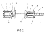
Fig. 2 discloses a sectional view of the clamping device according tofig. 1 . -
Fig. 3 discloses apartly exploded view of an end plate according to the present invention. -
Fig. 1 discloses a side view of a closedreactor frame 1 holding reactor orflow module plates 6 in place. According to this embodiment of theinvention distribution plates 15 andpressure plates 13 are placed on each side of the stack of reactor orflow module plates 6. The stack of reactor orflow module plates 6 are pressed and held together by a pressure applied by twoend plates 2, one on each side of thestack 6 outside thedistribution plates 15 which theend plates 2 are pressed together bytensioning rods 7 applied in holes in theend plates 2, which rods are tightened evenly to press thestack 6 together into sealing contact with each other. - To further evenly distribute the pressure over the whole area of the plates in the stack 6 a grid of
springs 11 is arranged in one of theend plates 2, which arrangement is disclosed infig. 2 . This is made possible by the U-shape construction of theend plates 2. Eachend plate 2 comprises anelongated beam flange 3 and a likewiseelongated beam web 4 arranged on each side of saidbeam flange 3 thus forming a U-shape beam construction. Eachbeam web 4 has agroove 5 along an edge of itslong side 8. The edges of the long side of thebeam flanges 3 are fitted in thegroove 5. To fix thewebs 4 and theflange 3 togetherbolts 9 are arranged in through holes along the edge of theweb 4 fastened in corresponding holes in theflange 3. As can be seen infig. 3 the edge of the long side of thebeam flange 3 may be stepped, i.e. the edge has atongue 10 of about half the thickness of the edge. In the embodiment according tofig. 2 thistongue 10 is fitted into thegroove 5 of thebeam webs 4.
To further fix the position of thebeam webs 4 in relation to thebeam flange 3 and strengthen the design, thegrooves 5 may havebridges 12 i.e. interruptions in agroove 5 at strategic positions, whichbridges 12 correspond to interruptions in theflanges 10 at the same positions. - As has been previously implied a clamping device according to the present invention may also be used with plate heat exchangers and other flow modules comprising plates.
- The above detailed description is not limited to the mentioned embodiments of the invention but to a person skilled in the art there are several modifications possible within the scope of the claimed invention.
Claims (3)
- Flow module, reactor or heat exchanger plate clamping device comprising two U-section formed end plates (2), springs (11), and tensioning rods (7), wherein at least one end plate (2) comprises, an elongated beam flange (3) and on each side of said beam flange (3) a beam web (4), where the long sides (8) of the beam webs (4) each has a groove (5) in which the beam flange (3) is fitted, in such a way that an end plate (2) with a U-section is formed.
- Flow module, reactor or heat exchanger plate clamping device according to claim 1, wherein the edge of the long side of the beam flange (3) is stepped, in such a way that it comprises a tongue (10) which is fitted in the groove (5) of the beam web (4).
- Flow module, reactor or heat exchanger plate clamping device according to claim 1, the grooves (5) have bridges (12), which bridges (12) correspond to interruptions in the flanges (10).
Priority Applications (1)
| Application Number | Priority Date | Filing Date | Title |
|---|---|---|---|
| EP10168219A EP2402696A1 (en) | 2010-07-02 | 2010-07-02 | Flow module, reactor or heat exchanger plate clamping device |
Applications Claiming Priority (1)
| Application Number | Priority Date | Filing Date | Title |
|---|---|---|---|
| EP10168219A EP2402696A1 (en) | 2010-07-02 | 2010-07-02 | Flow module, reactor or heat exchanger plate clamping device |
Publications (1)
| Publication Number | Publication Date |
|---|---|
| EP2402696A1 true EP2402696A1 (en) | 2012-01-04 |
Family
ID=43446679
Family Applications (1)
| Application Number | Title | Priority Date | Filing Date |
|---|---|---|---|
| EP10168219A Withdrawn EP2402696A1 (en) | 2010-07-02 | 2010-07-02 | Flow module, reactor or heat exchanger plate clamping device |
Country Status (1)
| Country | Link |
|---|---|
| EP (1) | EP2402696A1 (en) |
Cited By (2)
| Publication number | Priority date | Publication date | Assignee | Title |
|---|---|---|---|---|
| CN108908167A (en) * | 2018-08-07 | 2018-11-30 | 芜湖先力自动化设备有限公司 | A kind of new energy battery heat sink air-actuated jaw and application method |
| CN115164621A (en) * | 2022-06-21 | 2022-10-11 | 扬中申扬换热设备有限公司 | Modularization gas-gas heat exchanger convenient to slab is changed |
Citations (5)
| Publication number | Priority date | Publication date | Assignee | Title |
|---|---|---|---|---|
| GB442293A (en) * | 1934-08-16 | 1936-02-06 | Cherry Burrell Corp | Improvements in or relating to plate heat exchangers for fluids |
| EP0947795A1 (en) * | 1998-03-30 | 1999-10-06 | Balcke-Dürr GmbH | Heat exchanger with a plurality of tubes |
| WO2008066447A1 (en) | 2006-11-27 | 2008-06-05 | Alfa Laval Corporate Ab | A clamping device for flow module plates, reactor plates or heat exchanger plates |
| EP2051035A2 (en) * | 2007-10-15 | 2009-04-22 | Alfa Laval Corporate AB | Plate heat exchanger |
| WO2009142579A1 (en) | 2008-05-21 | 2009-11-26 | Alfa Laval Corporate Ab | Clamping system |
-
2010
- 2010-07-02 EP EP10168219A patent/EP2402696A1/en not_active Withdrawn
Patent Citations (5)
| Publication number | Priority date | Publication date | Assignee | Title |
|---|---|---|---|---|
| GB442293A (en) * | 1934-08-16 | 1936-02-06 | Cherry Burrell Corp | Improvements in or relating to plate heat exchangers for fluids |
| EP0947795A1 (en) * | 1998-03-30 | 1999-10-06 | Balcke-Dürr GmbH | Heat exchanger with a plurality of tubes |
| WO2008066447A1 (en) | 2006-11-27 | 2008-06-05 | Alfa Laval Corporate Ab | A clamping device for flow module plates, reactor plates or heat exchanger plates |
| EP2051035A2 (en) * | 2007-10-15 | 2009-04-22 | Alfa Laval Corporate AB | Plate heat exchanger |
| WO2009142579A1 (en) | 2008-05-21 | 2009-11-26 | Alfa Laval Corporate Ab | Clamping system |
Cited By (3)
| Publication number | Priority date | Publication date | Assignee | Title |
|---|---|---|---|---|
| CN108908167A (en) * | 2018-08-07 | 2018-11-30 | 芜湖先力自动化设备有限公司 | A kind of new energy battery heat sink air-actuated jaw and application method |
| CN108908167B (en) * | 2018-08-07 | 2024-03-01 | 芜湖先力自动化设备有限公司 | New energy battery cooling plate pneumatic clamp and application method thereof |
| CN115164621A (en) * | 2022-06-21 | 2022-10-11 | 扬中申扬换热设备有限公司 | Modularization gas-gas heat exchanger convenient to slab is changed |
Similar Documents
| Publication | Publication Date | Title |
|---|---|---|
| US10581042B2 (en) | End plate of battery module and battery module | |
| US8634194B2 (en) | Power conversion apparatus | |
| JP5685528B2 (en) | Clamping device | |
| US20140016993A1 (en) | Panel joint structure | |
| CN204456454U (en) | The adjustable assembly connection device of a kind of steel I-beam for building | |
| CN103840103A (en) | Battery for motor vehicle | |
| DE102015115643A1 (en) | Cooling module for one battery and battery with cooling module | |
| WO2015086670A2 (en) | Battery module | |
| MX2009005530A (en) | A clamping device for flow module plates, reactor plates or heat exchanger plates. | |
| WO2009075178A1 (en) | Fuel cell stack | |
| EP2267391A3 (en) | Asymmetric heat exchanger | |
| EP3659200A1 (en) | Systems and methods of fuel cell stack compression | |
| US10923755B2 (en) | Mount structure for fuel cell stack | |
| CN107112457A (en) | Receptacle for battery module and battery module with such a receptacle | |
| DE102016205124B3 (en) | battery Pack | |
| CN108028623B (en) | Stacking spacer, photovoltaic module frame and tracking device assembly | |
| US9746246B2 (en) | Plate heat exchanger in a sealed design | |
| SA517390003B1 (en) | Plate Exchanger for Chemical Reactors with Automatically Weldable Collectors | |
| KR101988738B1 (en) | Solar panel unit and solar panel structere | |
| CN108238104B (en) | Inclined pull beam for connecting supporting table and auxiliary frame and engineering truck | |
| DE102018109585A1 (en) | CONTRAPTION | |
| US9976651B2 (en) | Device to create a hermetic seal for large openings in equipment | |
| EP1116927A3 (en) | Heat exchanger with stacked plates, more particularly for reforming reactor | |
| US20170025701A1 (en) | A clamp assembly for a fuel cell stack and a method of assembling a fuel cell stack | |
| AT521905B1 (en) | battery module |
Legal Events
| Date | Code | Title | Description |
|---|---|---|---|
| AK | Designated contracting states |
Kind code of ref document: A1 Designated state(s): AL AT BE BG CH CY CZ DE DK EE ES FI FR GB GR HR HU IE IS IT LI LT LU LV MC MK MT NL NO PL PT RO SE SI SK SM TR |
|
| AX | Request for extension of the european patent |
Extension state: BA ME RS |
|
| PUAI | Public reference made under article 153(3) epc to a published international application that has entered the european phase |
Free format text: ORIGINAL CODE: 0009012 |
|
| 17P | Request for examination filed |
Effective date: 20120327 |
|
| STAA | Information on the status of an ep patent application or granted ep patent |
Free format text: STATUS: THE APPLICATION IS DEEMED TO BE WITHDRAWN |
|
| 18D | Application deemed to be withdrawn |
Effective date: 20120705 |