EP2402694B1 - Condenseur, notamment pour système de climatisation d'un vehicule automobile et échangeur de chaleur equipé d'un tel condenseur - Google Patents
Condenseur, notamment pour système de climatisation d'un vehicule automobile et échangeur de chaleur equipé d'un tel condenseur Download PDFInfo
- Publication number
- EP2402694B1 EP2402694B1 EP11170766.7A EP11170766A EP2402694B1 EP 2402694 B1 EP2402694 B1 EP 2402694B1 EP 11170766 A EP11170766 A EP 11170766A EP 2402694 B1 EP2402694 B1 EP 2402694B1
- Authority
- EP
- European Patent Office
- Prior art keywords
- bundle
- heat transfer
- condenser
- housing
- transfer fluid
- Prior art date
- Legal status (The legal status is an assumption and is not a legal conclusion. Google has not performed a legal analysis and makes no representation as to the accuracy of the status listed.)
- Not-in-force
Links
Images




Classifications
-
- F—MECHANICAL ENGINEERING; LIGHTING; HEATING; WEAPONS; BLASTING
- F28—HEAT EXCHANGE IN GENERAL
- F28F—DETAILS OF HEAT-EXCHANGE AND HEAT-TRANSFER APPARATUS, OF GENERAL APPLICATION
- F28F21/00—Constructions of heat-exchange apparatus characterised by the selection of particular materials
- F28F21/06—Constructions of heat-exchange apparatus characterised by the selection of particular materials of plastics material
- F28F21/065—Constructions of heat-exchange apparatus characterised by the selection of particular materials of plastics material the heat-exchange apparatus employing plate-like or laminated conduits
-
- F—MECHANICAL ENGINEERING; LIGHTING; HEATING; WEAPONS; BLASTING
- F25—REFRIGERATION OR COOLING; COMBINED HEATING AND REFRIGERATION SYSTEMS; HEAT PUMP SYSTEMS; MANUFACTURE OR STORAGE OF ICE; LIQUEFACTION SOLIDIFICATION OF GASES
- F25B—REFRIGERATION MACHINES, PLANTS OR SYSTEMS; COMBINED HEATING AND REFRIGERATION SYSTEMS; HEAT PUMP SYSTEMS
- F25B39/00—Evaporators; Condensers
- F25B39/04—Condensers
-
- F—MECHANICAL ENGINEERING; LIGHTING; HEATING; WEAPONS; BLASTING
- F28—HEAT EXCHANGE IN GENERAL
- F28D—HEAT-EXCHANGE APPARATUS, NOT PROVIDED FOR IN ANOTHER SUBCLASS, IN WHICH THE HEAT-EXCHANGE MEDIA DO NOT COME INTO DIRECT CONTACT
- F28D1/00—Heat-exchange apparatus having stationary conduit assemblies for one heat-exchange medium only, the media being in contact with different sides of the conduit wall, in which the other heat-exchange medium is a large body of fluid, e.g. domestic or motor car radiators
- F28D1/02—Heat-exchange apparatus having stationary conduit assemblies for one heat-exchange medium only, the media being in contact with different sides of the conduit wall, in which the other heat-exchange medium is a large body of fluid, e.g. domestic or motor car radiators with heat-exchange conduits immersed in the body of fluid
- F28D1/04—Heat-exchange apparatus having stationary conduit assemblies for one heat-exchange medium only, the media being in contact with different sides of the conduit wall, in which the other heat-exchange medium is a large body of fluid, e.g. domestic or motor car radiators with heat-exchange conduits immersed in the body of fluid with tubular conduits
- F28D1/0408—Multi-circuit heat exchangers, e.g. integrating different heat exchange sections in the same unit or heat exchangers for more than two fluids
-
- F—MECHANICAL ENGINEERING; LIGHTING; HEATING; WEAPONS; BLASTING
- F28—HEAT EXCHANGE IN GENERAL
- F28D—HEAT-EXCHANGE APPARATUS, NOT PROVIDED FOR IN ANOTHER SUBCLASS, IN WHICH THE HEAT-EXCHANGE MEDIA DO NOT COME INTO DIRECT CONTACT
- F28D7/00—Heat-exchange apparatus having stationary tubular conduit assemblies for both heat-exchange media, the media being in contact with different sides of a conduit wall
- F28D7/16—Heat-exchange apparatus having stationary tubular conduit assemblies for both heat-exchange media, the media being in contact with different sides of a conduit wall the conduits being arranged in parallel spaced relation
- F28D7/1684—Heat-exchange apparatus having stationary tubular conduit assemblies for both heat-exchange media, the media being in contact with different sides of a conduit wall the conduits being arranged in parallel spaced relation the conduits having a non-circular cross-section
-
- F—MECHANICAL ENGINEERING; LIGHTING; HEATING; WEAPONS; BLASTING
- F28—HEAT EXCHANGE IN GENERAL
- F28D—HEAT-EXCHANGE APPARATUS, NOT PROVIDED FOR IN ANOTHER SUBCLASS, IN WHICH THE HEAT-EXCHANGE MEDIA DO NOT COME INTO DIRECT CONTACT
- F28D9/00—Heat-exchange apparatus having stationary plate-like or laminated conduit assemblies for both heat-exchange media, the media being in contact with different sides of a conduit wall
- F28D9/0006—Heat-exchange apparatus having stationary plate-like or laminated conduit assemblies for both heat-exchange media, the media being in contact with different sides of a conduit wall the plate-like or laminated conduits being enclosed within a pressure vessel
-
- F—MECHANICAL ENGINEERING; LIGHTING; HEATING; WEAPONS; BLASTING
- F28—HEAT EXCHANGE IN GENERAL
- F28F—DETAILS OF HEAT-EXCHANGE AND HEAT-TRANSFER APPARATUS, OF GENERAL APPLICATION
- F28F21/00—Constructions of heat-exchange apparatus characterised by the selection of particular materials
- F28F21/06—Constructions of heat-exchange apparatus characterised by the selection of particular materials of plastics material
- F28F21/067—Details
-
- F—MECHANICAL ENGINEERING; LIGHTING; HEATING; WEAPONS; BLASTING
- F28—HEAT EXCHANGE IN GENERAL
- F28F—DETAILS OF HEAT-EXCHANGE AND HEAT-TRANSFER APPARATUS, OF GENERAL APPLICATION
- F28F9/00—Casings; Header boxes; Auxiliary supports for elements; Auxiliary members within casings
- F28F9/02—Header boxes; End plates
- F28F9/0234—Header boxes; End plates having a second heat exchanger disposed there within, e.g. oil cooler
-
- F—MECHANICAL ENGINEERING; LIGHTING; HEATING; WEAPONS; BLASTING
- F25—REFRIGERATION OR COOLING; COMBINED HEATING AND REFRIGERATION SYSTEMS; HEAT PUMP SYSTEMS; MANUFACTURE OR STORAGE OF ICE; LIQUEFACTION SOLIDIFICATION OF GASES
- F25B—REFRIGERATION MACHINES, PLANTS OR SYSTEMS; COMBINED HEATING AND REFRIGERATION SYSTEMS; HEAT PUMP SYSTEMS
- F25B2339/00—Details of evaporators; Details of condensers
- F25B2339/04—Details of condensers
- F25B2339/044—Condensers with an integrated receiver
-
- F—MECHANICAL ENGINEERING; LIGHTING; HEATING; WEAPONS; BLASTING
- F28—HEAT EXCHANGE IN GENERAL
- F28D—HEAT-EXCHANGE APPARATUS, NOT PROVIDED FOR IN ANOTHER SUBCLASS, IN WHICH THE HEAT-EXCHANGE MEDIA DO NOT COME INTO DIRECT CONTACT
- F28D21/00—Heat-exchange apparatus not covered by any of the groups F28D1/00 - F28D20/00
- F28D2021/0019—Other heat exchangers for particular applications; Heat exchange systems not otherwise provided for
- F28D2021/0068—Other heat exchangers for particular applications; Heat exchange systems not otherwise provided for for refrigerant cycles
- F28D2021/0073—Gas coolers
-
- F—MECHANICAL ENGINEERING; LIGHTING; HEATING; WEAPONS; BLASTING
- F28—HEAT EXCHANGE IN GENERAL
- F28D—HEAT-EXCHANGE APPARATUS, NOT PROVIDED FOR IN ANOTHER SUBCLASS, IN WHICH THE HEAT-EXCHANGE MEDIA DO NOT COME INTO DIRECT CONTACT
- F28D21/00—Heat-exchange apparatus not covered by any of the groups F28D1/00 - F28D20/00
- F28D2021/0019—Other heat exchangers for particular applications; Heat exchange systems not otherwise provided for
- F28D2021/008—Other heat exchangers for particular applications; Heat exchange systems not otherwise provided for for vehicles
- F28D2021/0084—Condensers
-
- F—MECHANICAL ENGINEERING; LIGHTING; HEATING; WEAPONS; BLASTING
- F28—HEAT EXCHANGE IN GENERAL
- F28F—DETAILS OF HEAT-EXCHANGE AND HEAT-TRANSFER APPARATUS, OF GENERAL APPLICATION
- F28F2225/00—Reinforcing means
- F28F2225/02—Reinforcing means for casings
Definitions
- the invention relates to a condenser, in particular for an air conditioning system of a motor vehicle. It also relates to a support device for one or more items of equipment of a motor vehicle front face and a heat exchanger equipped with such a condenser. More particularly, the invention relates to a condenser as defined in the preamble of claim 1, and as disclosed by the document EP 0 889 299 A2 .
- Air conditioning circuits for motor vehicles are now known comprising a refrigerant fluid compressor, which may for example be supercritical carbon dioxide CO 2 or the fluorinated refrigerant known under the reference R134a or even the fluid referenced 1234YF. Downstream of the compressor, the refrigerant under pressure passes through a heat exchanger called a “gas cooler” (“Gas Cooler”) for carbon dioxide or “condenser” for R134a because, in this case, the refrigerant initially in phase gas leaves the condenser in the liquid phase.
- Gas cooler gas cooler
- condenser condenser
- the refrigerant fluid is then led to a pressure reducer or a calibrated orifice before entering an evaporator where the heat exchange then takes place between the cooled refrigerant fluid and the air blown in the direction of the passenger compartment of the vehicle.
- the refrigerant, heated at the outlet of the evaporator, is finally returned to the compressor to carry out a new thermal cycle.
- the heat transfer fluid for heat exchange with the refrigerant fluid in the condenser can be outside air.
- the condenser is placed on the front face of the vehicle so as to be traversed by a flow of ambient air produced by the movement of the vehicle or by a fan. We then speak of an air condenser.
- the heat transfer fluid is water to which an antifreeze, glycol for example, has been added, circulating in a low temperature circuit using an electric pump between the condenser and a water/external air heat exchanger. We then speak of a water condenser.
- the invention proposes to overcome these drawbacks and relates to a condenser, in particular for an air conditioning system of a motor vehicle, comprising a housing and a heat exchange bundle, the condenser being configured to allow an exchange of heat between a fluid refrigerant flowing through the bundle and a coolant flowing through the housing.
- said casing is made of plastic.
- the casing for example by molding, by integrating therein several functions such as flanges or others.
- This provides a condenser using a heat transfer fluid which may be liquid having a simplified structure.
- the invention is defined as in claim 1.
- the invention also relates to a support device for one or more items of equipment of a motor vehicle front face, said support device comprising a nozzle capable of receiving the said item or items, and a condenser according to one any of the preceding claims, the housing of said condenser being attached to said nozzle. According to this mode of implementation, the condenser is thus integrated into the nozzle.
- the invention also relates to a heat exchanger comprising a heat transfer fluid exchange bundle with an air flow, an inlet manifold arranged to distribute the heat transfer fluid in said heat transfer fluid exchange bundle, an outlet manifold arranged to collect the heat transfer fluid from said heat transfer fluid exchange bundle, said inlet manifold and said outlet collector each comprising a housing closed by a collector plate, connected to the bundle, said exchanger further comprising a condenser as described above, the housing of the condenser being made up of the housing of the inlet and/or outlet collector.
- the condenser is thus integrated into the heat exchanger, the collector advantageously fulfilling the function of condenser casing to guide the heat transfer fluid.
- the air conditioning and exchange circuits are advantageously merged within the same unit, which limits the size while maintaining optimal performance.
- the water condenser is mounted in the front of the vehicle, like an air condenser, without increase the space on the front face.
- Another advantage of this solution is that it makes it possible to keep air conditioning circuit topologies relatively close to those with air condenser of the state of the art. This avoids having to design an entirely new architecture for the use of a water condenser.
- the manifold comprising a U-section housing
- the coolant exchange bundle is mounted integral with a first branch of the U.
- the coolant exchange bundle forms a structural assembly with the housing.
- the casing thus obtained can be assembled in a conventional manner to form the heat exchanger.
- the coolant exchange bundle is mounted at a distance from the second branch of the U so as to provide a space for the circulation of the heat transfer fluid between the second branch of the U and the coolant exchange bundle.
- the heat transfer fluid can circulate in the bundle and around the bundle so as to promote the transfer of heat by thermal conduction.
- the coolant fluid exchange bundle comprises an inlet pipe and a coolant fluid outlet pipe extending outside of said housing.
- the refrigerant fluid is advantageously introduced and evacuated via the housing, which makes it possible to form an air conditioning circuit by connecting to said refrigerant fluid inlet and outlet pipes which are accessible.
- At least one of said pipes comprises a threaded portion.
- a fastening nut secures said tubing to said casing.
- the threaded portion can advantageously fulfill a function of sealingly securing the refrigerant fluid exchange bundle to the housing and allowing connection to the air conditioning circuit.
- the collector comprises a coolant fluid pipe opening into said volume.
- the heat transfer fluid can thus be introduced/evacuated from the collector before/after exchange with the bundle of refrigerant fluid.
- the condenser is defined by the outlet collector.
- the refrigerant fluid can be cooled with a heat transfer fluid cooled by the exchanger. This advantageously improves the exchange performance of the bundle of refrigerant fluid.
- the heat transfer fluid exchange bundle extends orthogonally to the coolant fluid exchange bundle.
- the exchange performance of the bundle of refrigerant fluid is advantageously optimized due to the cross circulation of the two fluids.
- the heat transfer fluid exchange bundle comprising a plurality of heat transfer fluid circulation tubes
- the fluid exchange bundle refrigerant extends facing the mouth of the tubes of the heat transfer fluid exchange bundle.
- the circulation speed of the heat transfer fluid is then high when it circulates in the cooling bundle, which improves heat transfer by thermal conduction.
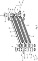
- the figures 1 to 8c show an exemplary heat exchanger which is not the subject of the invention, while the figures 9 to 12 show the claimed heat exchanger.
- the invention relates to a condenser, in particular for an air conditioning system of a motor vehicle, comprising a housing 7, 103 and a heat exchange bundle 5, 105.
- the condenser is configured to allow a heat exchange between a refrigerant flowing through the bundle 5, 105, and a heat transfer fluid passing through the housing 3B, 103.
- the beam 5, 105 is, for example, housed in the housing 7, 103.
- the refrigerant may be a fluorinated fluid, in particular that known as R134a. It could still be carbon dioxide or the liquid known as 1234YF.
- the heat transfer fluid is a liquid, for example, a mixture of water and antifreeze.
- the casing is made of plastic. It can thus be given many functions, taking into account the ease of shaping that such a material presents.
- the condenser is made in the collector of an exchanger of the intermediate tube type.
- a heat exchanger 1 comprises a bundle 2 for exchanging heat transfer fluid F2 with an air flow F3, an inlet manifold 3A, called a hot box, arranged to distribute the heat transfer fluid to be cooled F2 in said heat exchange bundle heat transfer fluid 2 and an outlet manifold 3B, called a cold box, arranged to collect the cooled heat transfer fluid F2 from said heat transfer fluid exchange bundle 2.
- the outlet manifold 3B further comprises the bundle 5 for exchanging the coolant fluid F1 mounted in the volume of the outlet manifold 3B so as to allow the cooling of the coolant fluid F1 by the cooled heat transfer fluid F2.
- the heat transfer fluid exchange bundle 2 F2 is designated heat transfer fluid bundle 2.
- the refrigerant fluid exchange bundle 5 F1 is subsequently designated refrigerant bundle 5.
- the heat transfer bundle 2 consists of a bundle of tubes 20 arranged in parallel on one or more rows, these tubes 20 are intended for the circulation through the exchanger 1 of a heat transfer fluid F2, such as water with added glycol in the case of engine cooling radiators.
- the heat transfer fluid F2 is introduced into the circulation tubes 20 via the inlet manifold 3A placed at the inlet of the heat transfer bundle 2 and provided with a fluid inlet pipe 11.
- the outlet collector 3B of the same type is installed at the outlet of the bundle 2 to collect the heat transfer fluid F2 having passed through the tubes 20 and evacuate it outside through an outlet pipe 12.
- the heat transfer bundle 2 comprises a single row of flat tubes 20, parallel to each other, extending longitudinally in a direction X.
- the tubes 20 are flattened so as to that the cross section of a tube 20 is in the form of an ellipse whose major diameter extends along a direction Z.
- the tubes 20 are flattened along the direction Y.
- the elements of the heat transfer bundle 2 are identified in an orthogonal frame (X, Y, Z).
- the tubes 20 of the heat transport bundle 2 extend along a longitudinal axis X.
- the terms “left” and “right” are defined with respect to the longitudinal axis X which extends from left to right on the figure 1 .
- the air flow F3 circulates orthogonally to the tubes 20 in the direction Z.
- the terms “upstream” and “downstream” are defined with respect to the axis Z which extends from upstream to downstream. on the figure 1 .
- the flattened shape of the tubes 20 makes it possible to maximize the exchange surface between the tubes 20 and the flow of air F3 circulating in the direction Z.
- the tubes 20 of the heat transfer bundle 2 are stacked vertically along the Y axis. Subsequently, the terms “lower” and “upper” are defined with respect to the Y axis which extends from the lower part of the heat transfer bundle 5 towards its upper part on the figure 1 as shown on the figure 2 .
- the vertical and horizontal directions are defined respectively along the X and Y axes as shown in the figure 2 illustrating the exchanger 1 in a vertical mounting position.
- the bundle may be a brazed assembly bundle, that is to say a bundle of tubes and spacers brazed together. It may also be a bundle with mechanical assembly, that is to say, a bundle of tubes and fins assembled by expansion of the tubes against the fins. The spacers or fins are used to increase the exchange surface with the air.
- the outlet collector 3B is made up of two parts, namely, a housing 7 and a collector plate 6.
- the following structural description relates more particularly to the collector output 3B but it applies similarly to the input collector 3A.
- Collector plate 6 shown in the figures 3 and 4 (which are not the subject of the invention), is a part in contact with the heat transfer bundle 2 and comprises orifices 61 intended to receive the end of the tubes 20 opening into the output collector 3B.
- the collector plate 6 has a substantially rectangular shape and extends orthogonally to the direction of the tubes 20 of the heat transfer bundle 2. In other words, the collector plate 6 extends parallel to the plane (Y, Z) to close the open face of the casing 7 as will be detailed below.
- a collector plate 6 is mounted at each of the ends of the heat transfer bundle 2 so as to hold the tubes 20 opening into the collectors 3A, 3B.
- a seal providing the seal between the casing 7 and the heat transfer bundle 2 is placed on the collector plate 6.
- the seal can do any the surface of the collector plate 6, orifices 61 being provided in the joint for the sealed passage of the tubes 20.
- the ends of the tubes 20 protrude inside the manifold 3B. The protrusion reaches approximately 2 to 3 mm for bundles of tubes with mechanical assembly. It is significantly lower for brazed bundles in which the tubes are brazed to the header plate.
- the orifices 61 of the collector plate 6 are oblong so as to allow a sealed assembly with the flattened tubes 20 of the heat transfer bundle 2.
- the housing 7 is in the form of a U-shaped channel, that is to say a parallelepiped having an open face, the collector plate 6 closing the U by crimping.
- the housing 7 defines with its collector plate 6 a volume of fluid circulating at the inlet and at the outlet of the exchanger 1 which is commonly referred to as collector 3A, 3B.
- the U-shaped chute whose housing 7 is shaped, comprises an upstream vertical wall 71, a bottom vertical wall 72, a downstream vertical wall 73, a lower horizontal wall 74 and an upper horizontal wall 75.
- the housing 7 of the outlet manifold 3B comprises a coolant fluid pipe F2 designated as tubing 12 which extends in the direction Z to allow the evacuation of the coolant fluid F2 at the outlet of the outlet manifold 3B.
- the outlet pipe 12 is here arranged in the upper part of the downstream vertical wall 73.
- the housing 7 of the inlet manifold 3A comprises a pipe 11 which extends in the direction Z to allow the introduction of the heat transfer fluid F2 in heat transfer bundle 2.
- the inlet pipe 11 is here arranged in the lower part of the inlet manifold 3A.
- the cooling bundle 5 comprises a plurality of stacked tubes 50 distributed in two rows R1, R2.
- the cooling bundle 5 forms a circulation circuit for a cooling fluid F1 which enters the cooling bundle 5 via a fluid inlet 51 and leaves via a fluid outlet 52.
- the cooling fluid F1 exchanges heat by thermal conduction with the heat transfer fluid F2 circulating between the tubes 50 of the bundle 5.
- the tubes 50 of the cooling bundle 5 extend along the longitudinal axis Y, the heat transfer fluid F2 flowing orthogonally to the tubes 50 in the direction X.
- the tubes 50 of a row R1, R2 of the cooling bundle 5 are stacked along the Z axis.
- the cooling bundle 5 is mounted in the outlet manifold 3B of the heat exchanger 1 arranged to conduct the heat transfer fluid F2 and to exchange heat with the air flow F3.
- this comprises a left row R1 and a right row R2 which each comprise three exchange units U1-U3, U4-U6 stacked along the Z axis.
- Each exchange unit U1-U3, U4-U6 comprises a block tubes 53, the ends of which are fixed in leaktight manner to collector elements 54 or end pieces.
- a block of tubes 53 comprises a stack of flat tubes 50 inside which the refrigerant fluid F1 circulates.
- the tubes 50 are made of metal, usually an aluminum alloy, and include coolant fluid circulation channels F1 in the form of parallel holes (not shown) extending over the entire length of the tubes 50.
- Each tube 50 has an outer surface which is in contact with the heat transfer fluid F2 so that the latter brings cold temperatures to the refrigerant fluid F1 by thermal conduction.
- the ends of the block of tubes 53 are mounted in a sealed manner in the collector elements 54 which make it possible to distribute or collect the refrigerant F1 in the block of tubes 53.
- a collector element 54 comprises a cylindrical body extending along the vertical axis Z and has a circular cross section.
- the body is open by its upper face as well as by its lower face and further comprises a connecting opening made in the transverse face of said body which opens along the Y axis to receive one end of a block of tubes 53.
- an exchange unit comprises a block of tubes 53 which is connected by its ends to the collector elements 54.
- An exchange unit U1-U6 corresponds to an elementary brick of the cooling bundle 5, the exchange units U1-U6 s interlocking with each other so as to form a refrigerant circulation circuit F1.
- the exchange units U1-U6 are stacked vertically along the Z axis in one or more rows R1, R2 which are then connected to form the bundle 5.
- a pipe 9 puts the first row R1 in fluid communication with the second row R2.
- a row of the cooling bundle 5 can include one or more passes to circulate the cooling fluid F1.
- the term “pass” is understood to mean one or more exchange units traversed in parallel by the refrigerant fluid F1. So, with reference to the figure 7 , the left row R1 of the beam 5 comprises a single pass and the right row R2 comprises two passes, a separation cover 55 being mounted between two collector elements 54 of the right row R2 so as to divert the circulation of the cooling flow F1. It goes without saying that a row of exchange beam can comprise more than two passes, for example three.
- the cooling bundle 5 advantageously comprises more exchange units in an upstream pass than in a downstream pass in the direction of the circulation of the cooling fluid F1.
- the refrigerant fluid F1 is introduced into the bundle 5 from the inlet 51 and leaves from the outlet 52 after crossing all of the exchange units U1-U6.
- the exchange units U1-U3 of the left row R1 are connected in parallel and the exchange units U4-U5 of the right row R2 are connected in parallel.
- the group of exchange units U1-U3, the group of exchange units U4-U5 and the exchange unit U6 are connected in series so that the refrigerant fluid F1 which enters the refrigerant bundle 5 via the inlet 51 successively crosses three exchange units (U1-U3) then two (U4-U5) and finally one (U6) to come out via the outlet 52.
- the refrigerant fluid F1 circulates in the cooling bundle 5 in three passes distributed over two rows R1, R2.
- a clip 56 extends substantially along the X axis and comprises two curved parts intended to respectively hold the bodies of the collector elements 54 of the exchange units of the left row R1 and of the right row R2, the curved parts being connected by a tenon , extending substantially rectilinearly.
- the inlet and the outlet of the refrigerant fluid F1 of the refrigerant bundle 5 are respectively in the form of cylindrical inlet 51 and outlet 52 pipes extending in the Z direction and whose free end is threaded to allow mounting of the refrigerant bundle 5 in the outlet manifold 3B.
- the cooling bundle 5 is mounted integral with the housing 7 in the volume of the outlet manifold 3B so that the cylindrical inlet 51 and outlet 52 pipes of the cooling bundle 5 extend respectively through an inlet orifice 76 and an outlet orifice 77 made in the downstream vertical wall 73 as shown in the figure 8A .
- Securing nuts 8 are fixed to the free ends of the cylindrical inlet 51 and outlet 52 pipes so as to secure the cooling bundle 5 to the casing 7.
- the cooling bundle 5 is introduced into the housing 7 by its open face by moving it in the direction X.
- the dimension of the cooling bundle 5 is less than the dimension of the casing 7 along the direction X so as to allow the introduction of the cooling bundle 5 with its cylindrical inlet 51 and outlet 52 pipes into the casing 7.
- the cooling bundle 5 is moved in the direction Z so as to that the cylindrical pipes 51, 52 protrude through the downstream vertical wall 73 of the casing 7 as shown in the figure 8B .
- the fastening nuts 8 are then screwed to the threaded ends of the cylindrical pipes 51, 52 as shown in the Fig. 8C in order to ensure the mechanical connection between the cooling bundle 5 and the box 7.
- the tubes 50 of the cooling bundle 5 extend in the lower part of the outlet manifold 3B.
- the refrigerant bundle 5 is offset vertically with respect to the outlet pipe 12 of the exchanger 1.
- the tubes 50 of the cooling bundle 5 are stacked in the direction Z so that a tube 20 of the heat transfer bundle 2, which has an oblong section of large diameter extending in the direction Z, sends the flow heat carrier F2 which it leads over all of the stacked tubes of the cooling bundle 5.
- the cooling bundle 2 extends orthogonally to the cooling bundle 5, the cooling bundle 5 extending opposite the mouth tubes 20 of the heat transfer bundle 2.
- the cooling bundle 5 is mounted at a distance from the upstream vertical wall 71 so as to provide a space "d" for circulation of the heat transfer fluid F2 between the upstream vertical wall 71 and the cooling bundle 5.
- This advantageously makes it possible to facilitate the circulation of the heat transfer fluid F2 in the outlet manifold 3B by limiting pressure drops in said manifold 3B.
- the heat exchanger 1 conducts the heat transfer fluid F2 from its inlet manifold 3A to the outlet manifold 3B and exchanges heat by thermal conduction with the air flow F3 when the heat transfer fluid F2 passes through the heat transfer bundle 2.
- the tubes 20 of the heat transfer bundle 2 inject into the outlet manifold 3B the cooled heat transfer flow F2 which circulates, in the lower part of the casing 3B, through the cooling bundle 5 and which circulates, in the upper part of the casing 3B, directly towards the outlet pipe 12.
- the heat transfer fluid F2 circulates between the tubes 50 of the cooling bundle 5 to cool the cooling fluid F1 which circulates in passes in the said cooling bundle 5.
- the heat transfer fluid F2 is routed to the outlet pipe 12 of the exchanger 1.
- the refrigerant fluid F1 is for its part introduced and evacuated from the cooling bundle 5 by the cylindrical pipes 51, 52 which open out from the downstream vertical wall 73.
- the cylindrical outlet pipe 52 of the cooling bundle 5 is arranged close to the outlet pipe 12 of the heat exchanger 1 but it goes without saying that the cooling bundle 5 could also be mounted in the opposite direction with its cylindrical inlet pipe 51 arranged close to the outlet pipe 12 of the heat exchanger 1.
- a heat exchanger 1 has been presented with the cooling bundle 5 integrated in its outlet manifold 3B, but it could also be mounted in the inlet manifold 3A.
- beam 5 could have another structure.
- the condenser according to the invention can also to be independent.
- the heat exchanger shown in the Figures 9-12 is the object of the invention. Its preferred embodiment is claimed in claim 1.
- Its box 103 is configured, for example, to force a circulation of the heat transfer fluid through the beam 105, visible at the level of a scratched zone to the figures 9 and 10 .
- the housing has, in particular, a first zone 107 in contact with the beam and at least a second zone 109 at a distance from the beam to define collectors 111a, 111b for the heat transfer fluid so that said heat transfer fluid passes from a coolant fluid inlet 113ade, communicating with one 111a of the manifolds, to a coolant fluid outlet 113b, communicating with another one of the manifolds 111b, passing through a circulation path of the coolant fluid through said bundle 105 at the level of said first area 107.
- the bundle 105 comprises a stack of tubes 115 opening at their end into superimposed collector elements 117.
- the collector elements 117 communicate with each other through orifices, not shown, to define collectors for the refrigerant, on either side of the tubes 115.
- the refrigerant circulates in the tubes 115, in particular provided with multichannels, and the heat transfer fluid circulates between the tubes 115.
- the bundle 105 will define, for example, a first path for the refrigerant fluid and a second path for the heat transfer fluid.
- the tubes 115 are in contact with the casing 103 while the casing 103 moves away from the beam at the level of the collector elements 117.
- the collectors 111a, 111b for the heat transfer fluid are located at the level of said collector elements. 117.
- the heat transfer fluid can thus be distributed between the tubes 115 and then travel through the beam between said manifolds 111a, 111b being channeled between said tubes 115. This prevents part of the heat transfer fluid from passing directly from the inlet 113a to the outlet 113b of the exchanger without exchanging with the refrigerant.
- said first zone 107 is provided at the level of the tubes 115 and said second zone 109 is provided at the level of the collector elements 117.
- Said casing 103 has, for example, inlet 119a and/or outlet 119b pipes for the heat transfer fluid, made from material. They open into the collectors 111a, 111b.
- Said box 103 may also have reinforcing ribs 121, made from material.
- Said ribs 121 have, for example, a crossed configuration.
- the box 103 has a substantially parallelepipedic shape and the ribs 121 are parallel to the edges of the box.
- Said housing 103 may also have flanges 123 for fixing the condenser to a support, said flanges being made from material.
- Said fixing flanges 123 are located, for example, at one or more said reinforcing ribs 121, in particular, between two said ribs 121.
- the box 103 is closed, for example, by a cover 125, in particular made of metal, which can be crimped onto it.
- the cover defines, for example, an end plate of the beam 105.
- the beam 105 is integral with the cover 125.
- the heat exchange bundle 105 has, in particular, inlet-outlet pipes 127a, 127b emerging through the cover 125.
- these pipes 127a, 127b communicate with a bottle 129 which can be carried by the lid 125.
- a bottle serving, in a manner known to those skilled in the art, to define a fluid reserve volume refrigerant. It may also be used to filter it and/or ensure that it comes into contact with a desiccant, placed inside it. Said bottle may also be configured to allow a separation of phases, making it possible to eliminate any parts still in the vapor phase of the refrigerant at the outlet of the condenser before it continues its journey.
- the refrigerant fluid thus enters the condenser, via the inlet pipe 127a, passes through the collector elements 117 located at a first end of the tubes 115, enters the tubes 115 which it travels through, emerges in the collector elements 117 located at the other end of the tubes 115 to then leave the condenser through the outlet pipe 127b.
- the condenser is fixed, for example, to a nozzle of a support device for one or more items of equipment of a motor vehicle front face, said nozzle being provided capable of receiving said item(s) of equipment. It is, for example, a nozzle integrating a stator of a ventilation device. Said nozzle also being made of plastic, fixing the condenser is simplified.
Landscapes
- Engineering & Computer Science (AREA)
- Physics & Mathematics (AREA)
- Thermal Sciences (AREA)
- Mechanical Engineering (AREA)
- General Engineering & Computer Science (AREA)
- Air-Conditioning For Vehicles (AREA)
- Heat-Exchange Devices With Radiators And Conduit Assemblies (AREA)
Description
- L'invention concerne un condenseur, notamment pour système de climatisation d'un véhicule automobile. Elle concerne également un dispositif de support d'un ou plusieurs éléments d'équipement d'une face avant de véhicule automobile et un échangeur de chaleur équipé d'un tel condenseur. Plus particulièrement, l'invention se rapporte à un condenseur tel que défini au préambule de la revendication 1, et tel que divulgué par le document
EP 0 889 299 A2 . - On connaît aujourd'hui des circuits de climatisation pour véhicule automobiles comprenant un compresseur de fluide réfrigérant, qui peut être par exemple du dioxyde de carbone CO2 supercritique ou le réfrigérant fluoré connu sous la référence R134a ou encore le fluide référencé 1234YF. En aval du compresseur, le fluide réfrigérant sous pression traverse un échangeur de chaleur appelé « refroidisseur de gaz » (« Gas Cooler ») pour le dioxyde de carbone ou « condenseur » pour le R134a car, dans ce cas, le réfrigérant initialement en phase gazeuse sort du condenseur en phase liquide. Pour simplifier le vocabulaire, on utilisera dans la suite le seul terme de « condenseur » pour désigner ce type d'échangeur de chaleur.
- Le fluide réfrigérant est ensuite conduit vers un détendeur ou un orifice calibré avant de pénétrer dans un évaporateur où se produit alors l'échange de chaleur entre le fluide réfrigérant refroidi et de l'air pulsé en direction de l'habitacle du véhicule. Le fluide réfrigérant, réchauffé en sortie de l'évaporateur, est finalement retourné au compresseur pour effectuer un nouveau cycle thermique.
- Le fluide caloporteur d'échange de chaleur avec le fluide réfrigérant dans le condenseur peut être de l'air extérieur. Dans ce cas, le condenseur est placé en face avant du véhicule de manière à être traversé par un flux d'air ambiant produit par le déplacement du véhicule ou par un ventilateur. On parle alors de condenseur à air.
- Pour différentes raisons, notamment d'encombrement de la face avant du véhicule liées en particulier au problème de la sécurité des piétons, il est avantageux de ne plus employer de condenseur à air. Dans cette configuration, le fluide caloporteur est de l'eau additionnée d'un antigel, glycol par exemple, circulant dans un circuit basse température à l'aide d'une pompe électrique entre le condenseur et un échangeur de chaleur eau/air extérieur. On parle alors de condenseur à eau.
- De nombreuses configurations de condenseurs à eau ont été déjà été proposées. Ils ont une structure entièrement métallique. Un premier inconvénient rencontré avec une telle structure est qu'elle nécessite l'utilisation de brides de fixation et d'entrée/sortie de fluide, rapportées. Un autre inconvénient est qu'elle nécessite l'utilisation de pièces embouties dont la précision des côtes est difficilement maîtrisable. Elle présente ainsi des difficultés d'assemblage qui joue sur leur fiabilité et son coût de revient.
- L'invention se propose de pallier ces inconvénients et concerne un condenseur, notamment pour système de climatisation d'un véhicule automobile, comprenant un boîtier et un faisceau d'échange de chaleur, le condenseur étant configuré pour permettre un échange de chaleur entre un fluide frigorigène parcourant le faisceau et un fluide caloporteur traversant le boîtier. Selon l'invention, ledit boîtier est en plastique.
- On peut ainsi réaliser le boîtier, par exemple par moulage, en intégrant dans celui-ci plusieurs fonctions telles que brides ou autres. On dispose de la sorte d'un condenseur utilisant un fluide caloporteur pouvant être liquide présentant une structure simplifiée.
- L'invention est définie comme dans la revendication 1.
- Selon différents modes de réalisation :
- ledit boîtier présente des nervures de renfort et/ou des brides de fixation du condenseur à un support, issues de matière;
- lesdites brides de fixations sont situées au niveau d'une ou plusieurs nervures de renforts.
- L'invention concerne aussi un dispositif de support d'un ou plusieurs éléments d'équipement d'une face avant de véhicule automobile, ledit dispositif de support comprenant une buse apte, à accueillir le ou lesdits éléments, et un condenseur selon l'une quelconque des revendications précédentes, le boîtier dudit condenseur étant fixé à ladite buse. Selon ce mode de mise en oeuvre, le condenseur est ainsi intégré à la buse.
- L'invention concerne encore un échangeur de chaleur comprenant un faisceau d'échange de fluide caloporteur avec un flux d'air, un collecteur d'entrée agencé pour distribuer le fluide caloporteur dans ledit faisceau d'échange de fluide caloporteur, un collecteur de sortie agencé pour collecter le fluide caloporteur issu dudit faisceau d'échange de fluide caloporteur, ledit collecteur d'entrée et ledit collecteur de sortie comprenant chacun un boîtier fermé par une plaque collectrice, reliée au faisceau, ledit échangeur comprenant en outre un condenseur tel que décrit plus haut, le boîtier du condenseur étant constitué du boîtier du collecteur d'entrée et/ou de sortie.
- Selon ce mode de mise en oeuvre, le condenseur est ainsi intégré à l'échangeur de chaleur, le collecteur remplissant avantageusement la fonction de carter de condenseur pour guider le fluide caloporteur. Les circuits de climatisation et d'échange sont avantageusement fusionnés au sein d'une même unité ce qui limite l'encombrement tout en conservant des performances optimales.
- Dans le cas d'un échangeur se présentant sous la forme d'un radiateur et d'un condenseur à eau, le condenseur à eau est monté dans la face avant du véhicule, à la manière d'un condenseur à air, sans pour autant augmenter l'encombrement en face avant. Un autre avantage de cette solution est qu'elle permet de garder des topologies de circuit de climatisation relativement proches de celles avec condenseur à air de l'état de la technique. On évite ainsi d'avoir à concevoir une architecture entièrement nouvelle pour l'utilisation d'un condenseur à eau.
- De préférence, le collecteur comportant un boîtier de section en U, le faisceau d'échange de fluide réfrigérant est monté solidaire d'une première branche du U. Ainsi, le faisceau d'échange de fluide réfrigérant forme un ensemble structural avec le boîtier. Le boîtier ainsi obtenu peut être assemblé de manière conventionnelle pour former l'échangeur de chaleur.
- De préférence encore, le faisceau d'échange de fluide réfrigérant est monté à distance de la deuxième branche du U de manière à ménager un espace de circulation du fluide caloporteur entre la deuxième branche du U et le faisceau d'échange de fluide réfrigérant. Ainsi, le fluide caloporteur peut circuler dans le faisceau et autour du faisceau de manière à favoriser le transfert de chaleur par conduction thermique.
- Selon un aspect de l'invention, le faisceau d'échange de fluide réfrigérant comporte une tubulure d'entrée et une tubulure de sortie de fluide réfrigérant s'étendant extérieurement audit boîtier. Le fluide réfrigérant est avantageusement introduit et évacué via le boîtier ce qui permet de former un circuit de climatisation en se connectant auxdites tubulure d'entrée et de sortie de fluide réfrigérant qui sont accessibles.
- De préférence, au moins une desdites tubulures comporte une portion filetée. De préférence encore, un écrou de fixation solidarise ladite tubulure audit boîtier. La portion filetée peut remplir avantageusement une fonction de solidarisation étanche du faisceau d'échange de fluide réfrigérant au boîtier et permettre la connexion au circuit de climatisation.
- Selon un aspect de l'invention, le collecteur comporte une canalisation de fluide caloporteur débouchant dans ledit volume. Le fluide caloporteur peut ainsi être introduit/évacué du collecteur avant/après échange avec le faisceau de fluide réfrigérant.
- Selon un aspect de l'invention le condenseur est défini par le collecteur de sortie. Dans cette configuration, on peut refroidir le fluide réfrigérant avec un fluide caloporteur refroidi par l'échangeur. Cela améliore de manière avantageuse les performances d'échange du faisceau de fluide réfrigérant.
- De préférence, le faisceau d'échange de fluide caloporteur s'étend orthogonalement au faisceau d'échange de fluide réfrigérant. Les performances d'échange du faisceau de fluide réfrigérant sont avantageusement optimisées du fait de la circulation croisée des deux fluides.
- De préférence, le faisceau d'échange de fluide caloporteur comportant une pluralité de tubes de circulation de fluide caloporteur, le faisceau d'échange de fluide réfrigérant s'étend en regard de l'embouchure des tubes du faisceau d'échange de fluide caloporteur. La vitesse de circulation du fluide caloporteur est alors élevée lorsqu'il circule dans le faisceau réfrigérant ce qui améliore le transfert de chaleur par conduction thermique.
- Les
figures 1 à 8c montrent un échangeur de chaleur exemplaire qui ne fait pas l'objet de l'invention, tandis que lesfigures 9 à 12 montrent l'échangeur de chaleur revendiqué. - Dans la description détaillée qui suit, faite seulement à titre d'exemple, on se réfère aux dessins annexés, sur lesquels :
- la
figure 1 est une vue simplifiée en perspective d'un échangeur de chaleur muni d'un exemple de réalisation d'un condenseur; - la
figure 2 est une vue schématique en coupe de l'échangeur de chaleur de lafigure 1 ; - la
figure 3 est une vue schématique en coupe transversale de côté du collecteur de sortie de l'échangeur de chaleur de lafigure 1 fermé par une plaque collectrice et dans lequel est monté un faisceau parcouru par un fluide réfrigérant ; - la
figure 4 est une vue schématique de face de la plaque collectrice du collecteur de lafigure 3 ; - la
figure 5 est une vue schématique de face du collecteur de sortie ; - la
figure 6 est une vue schématique de la circulation du fluide réfrigérant ; - la
figure 7 est une vue éclatée du faisceau parcouru par un fluide réfrigérant ; - la
figure 8A est une vue en perspective de l'étape d'introduction du faisceau parcouru par un fluide réfrigérant dans le collecteur de sortie ; - la
figure 8B est une vue en perspective de l'étape de positionnement du faisceau parcouru par un fluide réfrigérant dans le collecteur de sortie; et - la
figure 8C est une vue en perspective de l'étape de solidarisation du faisceau parcouru par un fluide réfrigérant au collecteur de sortie, - la
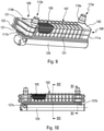
figure 9 illustre en perspective un autre exemple de réalisation du condenseur selon l'invention, - la
figure 10 est une vue de coté du condenseur selon lafigure 9 , - la
figure 11 est une vue de coupe effectuée selon la ligne XI-XI de lafigure 10 , - la
figure 12 est une vue de coupe effectuée selon la ligne XII-XII de lafigure 10 . - Comme illustré aux
figures 1 à 3 ,5 (qui ne sont pas l'objet de l'invention), 8 et 9 à 13 (qui sont l'objet de l'invention), l'invention concerne un condenseur, notamment pour système de climatisation d'un véhicule automobile, comprenant un boîtier 7, 103 et un faisceau d'échange de chaleur 5, 105. - Le condenseur est configuré pour permettre un échange de chaleur entre un fluide frigorigène parcourant le faisceau 5, 105, et un fluide caloporteur traversant le boîtier 3B, 103. Le faisceau 5, 105 est, par exemple, logé dans le boîtier 7, 103.
- Le fluide frigorigène pourra être un fluide fluoré, notamment celui connu sous le nom de R134a. Il pourra encore s'agir de dioxyde de carbone ou du liquide connu sous le nom de 1234YF. Le fluide caloporteur est un liquide, par exemple, un mélange d'eau et d'antigel.
- Selon l'invention, le boîtier est en plastique. On peut ainsi lui conférer de nombreuses fonctions compte-tenu de la facilité de mise en forme que présente une telle matière.
- Selon le mode de réalisation des
figures 1 à 8 (qui ne sont pas l'objet de l'invention), le condenseur est réalisé dans le collecteur d'un échangeur de type tubes intercalaires. - Plus précisément, en référence à la
figure 1 (qui n'est pas l'objet de l'invention), un échangeur de chaleur 1 comprend un faisceau 2 d'échange de fluide caloporteur F2 avec un flux d'air F3, un collecteur d'entrée 3A, appelé boîte chaude, agencé pour distribuer le fluide caloporteur à refroidir F2 dans ledit faisceau d'échange de fluide caloporteur 2 et un collecteur de sortie 3B, appelé boîte froide, agencé pour collecter le fluide caloporteur refroidi F2 issu dudit faisceau d'échange de fluide caloporteur 2. - Dans cette forme de réalisation, le collecteur de sortie 3B comprend en outre le faisceau 5 d'échange du fluide réfrigérant F1 monté dans le volume du collecteur de sortie 3B de manière à permettre le refroidissement du fluide réfrigérant F1 par le fluide caloporteur refroidi F2.
- Par la suite, le faisceau 2 d'échange de fluide caloporteur F2 est désigné faisceau caloporteur 2. De même, le faisceau 5 d'échange de fluide réfrigérant F1 est désigné par la suite faisceau réfrigérant 5.
- Le faisceau caloporteur 2 est constitué par un faisceau de tubes 20 disposés parallèlement sur une ou plusieurs rangées, ces tubes 20 sont destinés à la circulation à travers l'échangeur 1 d'un fluide caloporteur F2, tel que de l'eau additionnée de glycol dans le cas des radiateurs de refroidissement de moteurs. Le fluide caloporteur F2 est introduit dans les tubes de circulation 20 par l'intermédiaire du collecteur d'entrée 3A placé à l'entrée du faisceau caloporteur 2 et muni d'une tubulure d'arrivée 11 du fluide. Le collecteur de sortie 3B du même type est installé à la sortie du faisceau 2 pour recueillir le fluide caloporteur F2 ayant traversé les tubes 20 et l'évacuer à l'extérieur à travers une tubulure de sortie 12.
- Dans cet exemple, en référence aux
figures 1 et 2 (qui ne sont pas l'objet de l'invention), le faisceau caloporteur 2 comporte une unique rangée de tubes plats 20, parallèles les uns aux autres, s'étendant longitudinalement selon une direction X. Les tubes 20 sont aplatis de manière à ce que la section transversale d'un tube 20 se présente sous la forme d'une ellipse dont le grand diamètre s'étend selon une direction Z. Autrement dit, les tubes 20 sont aplatis selon la direction Y. - Par la suite, les éléments du faisceau caloporteur 2 sont repérés dans un repère orthogonal (X, Y, Z). En référence à la
figure 1 , les tubes 20 du faisceau caloporteur 2 s'étendent selon un axe longitudinal X. Par la suite, les termes « gauche » et « droite » sont définis par rapport à l'axe longitudinal X qui s'étend de la gauche vers la droite sur lafigure 1 . Le flux d'air F3 circule orthogonalement aux tubes 20 selon la direction Z. Par la suite, les termes « amont » et « aval » sont définis par rapport à l'axe Z qui s'étend de l'amont vers l'aval sur lafigure 1 . Ainsi, la forme aplatie des tubes 20 permet de maximiser la surface d'échange entre les tubes 20 et le flux d'air F3 circulant dans la direction Z. - Les tubes 20 du faisceau caloporteur 2 sont empilés verticalement selon l'axe Y. Par la suite, les termes « inférieur » et « supérieur » sont définis par rapport à l'axe Y qui s'étend de la partie inférieure du faisceau caloporteur 5 vers sa partie supérieure sur la
figure 1 comme représenté sur lafigure 2 . Les directions verticale et horizontale sont définies respectivement selon les axes X et Y comme représentés sur lafigure 2 illustrant l'échangeur 1 dans une position de montage verticale. - Le faisceau pourra être un faisceau à assemblage brasé, c'est-à-dire un faisceau de tubes et d'intercalaires brasés ensemble. Il pourra aussi s'agir d'un faisceau à assemblage mécanique, c'est-à-dire, un faisceau de tubes et d'ailettes assemblés par expansion des tubes contre les ailettes. Les intercalaires ou ailettes servent à augmenter la surface d'échange avec l'air.
- En référence maintenant à la
figure 3 (qui n'est pas l'objet de l'invention), le collecteur de sortie 3B est constitué de deux parties, à savoir, un boîtier 7 et une plaque collectrice 6. La description structurelle qui suit s'attache plus particulièrement au collecteur de sortie 3B mais elle s'applique de manière similaire au collecteur d'entrée 3A. - La plaque collectrice 6, représentée sur les
figures 3 et 4 (qui ne sont pas l'objet de l'invention), est une pièce en contact avec le faisceau caloporteur 2 et comporte des orifices 61 destinés à recevoir l'extrémité des tubes 20 débouchant dans le collecteur de sortie 3B. La plaque collectrice 6 possède une forme sensiblement rectangulaire et s'étend orthogonalement à la direction des tubes 20 du faisceau caloporteur 2. Autrement dit, la plaque collectrice 6 s'étend parallèlement au plan (Y, Z) pour fermer la face ouverte du boîtier 7 comme cela sera détaillé par la suite. - Comme représenté sur la
figure 2 , une plaque collectrice 6 est montée à chacune des extrémités du faisceau caloporteur 2 de manière à maintenir les tubes 20 débouchant dans les collecteurs 3A, 3B. - Dans le cas de radiateur avec plaque collectrice en métal et boîtier en plastique, un joint assurant l'étanchéité entre le boîtier 7 et le faisceau caloporteur 2 est disposé sur la plaque collectrice 6. Pour les faisceaux à assemblage mécanique, le joint pourra faire toute la surface de la plaque collectrice 6, des orifices 61 étant prévus dans le joint pour le passage étanche des tubes 20. En référence à la
figure 3 , les extrémités des tubes 20 dépassent à l'intérieur du collecteur 3B. Le dépassement atteint 2 à 3 mm environ pour les faisceaux de tubes à assemblage mécanique. Il est sensiblement plus faible pour les faisceaux brasés dans lesquels les tubes sont brasés à la plaque collectrice. - En référence maintenant à la
figure 4 (qui n'est pas l'objet de l'invention), les orifices 61 de la plaque collectrice 6 sont oblongs de manière à permettre un montage étanche avec les tubes aplatis 20 du faisceau caloporteur 2. - Le boîtier 7 se présente sous la forme d'une goulotte en forme de U, c'est-à-dire d'un parallélépipède ayant une face ouverte, la plaque collectrice 6 venant fermer le U par sertissage. Le boîtier 7 définit avec sa plaque collectrice 6 un volume de fluide en circulation à l'entrée comme à la sortie de l'échangeur 1 qui est communément désigné collecteur 3A, 3B. En référence aux
figures 3 et5 , la goulotte en U, dont le boîtier 7 à la forme, comporte une paroi verticale amont 71, une paroi verticale de fond 72, une paroi verticale aval 73, une paroi horizontale inférieure 74 et une paroi horizontale supérieure 75. - Comme représenté sur la
figure 1 , le boîtier 7 du collecteur de sortie 3B comporte une canalisation de fluide caloporteur F2 désignée tubulure 12 qui s'étend selon la direction Z pour permettre l'évacuation du fluide caloporteur F2 en sortie du collecteur de sortie 3B. La tubulure de sortie 12 est ici ménagée dans la partie supérieure de la paroi verticale aval 73. De manière similaire, le boîtier 7 du collecteur d'entrée 3A comporte une tubulure 11 qui s'étend selon la direction Z pour permettre l'introduction du fluide caloporteur F2 dans faisceau caloporteur 2. La tubulure d'entrée 11 est ici ménagée dans la partie inférieure du collecteur d'entrée 3A. - Avant d'aborder plus en détails le montage du faisceau réfrigérant 5 dans le collecteur de sortie 3B, les composants du faisceau réfrigérant 5 vont être présentés plus en avant.
- En référence à la
figure 5 (qui n'est pas l'objet de l'invention), le faisceau réfrigérant 5 comprend une pluralité de tubes empilés 50 répartis selon deux rangs R1, R2. Le faisceau réfrigérant 5 forme un circuit de circulation d'un fluide réfrigérant F1 qui pénètre dans le faisceau réfrigérant 5 via une entrée de fluide 51 et ressort via une sortie de fluide 52. Le fluide réfrigérant F1 échange de la chaleur par conduction thermique avec le fluide caloporteur F2 circulant entre les tubes 50 du faisceau 5. - En référence à la
figure 7 , les tubes 50 du faisceau réfrigérant 5 s'étendent selon l'axe longitudinal Y, le fluide caloporteur F2 circulant orthogonalement aux tubes 50 selon la direction X. Les tubes 50 d'un rang R1, R2 du faisceau réfrigérant 5 sont empilés selon l'axe Z. Comme représenté sur lafigure 5 , le faisceau réfrigérant 5 est monté dans le collecteur de sortie 3B de l'échangeur de chaleur 1 agencé pour conduire le fluide caloporteur F2 et pour échanger de la chaleur avec le flux d'air F3. - En référence à la
figure 7 représentant schématiquement le faisceau réfrigérant 5, celui-ci comporte un rang gauche R1 et un rang droit R2 qui comprennent chacun trois unités d'échange U1-U3, U4-U6 empilées selon l'axe Z. Chaque unité d'échange U1-U3, U4-U6 comporte un bloc de tubes 53 dont les extrémités sont fixées de façon étanche à des éléments collecteurs 54 ou embouts. - Un bloc de tubes 53 comporte un empilement de tubes plats 50 à l'intérieur desquels circule le fluide réfrigérant F1. Les tubes 50 sont en métal, le plus souvent en alliage d'aluminium, et comprennent des canaux de circulation de fluide réfrigérant F1 se présentant sous la forme de trous parallèles (non représentés) s'étendant sur toute la longueur des tubes 50. Chaque tube 50 comporte une surface extérieure qui est en contact avec le fluide caloporteur F2 de manière à ce que ce dernier apporte des frigories au fluide réfrigérant F1 par conduction thermique.
- En référence à la
figure 5 , les extrémités de bloc de tubes 53 sont montées de façon étanche dans les éléments collecteurs 54 qui permettent de distribuer ou de collecter le fluide réfrigérant F1 dans le bloc de tubes 53. - Comme représenté sur la
figure 7 , un élément collecteur 54 comporte un corps cylindrique s'étendant selon l'axe vertical Z et possède une section transversale circulaire. Le corps est ouvert par sa face supérieure ainsi que par sa face inférieure et comporte, en outre, une ouverture de liaison ménagée dans la face transversale dudit corps qui débouche selon l'axe Y pour recevoir une extrémité de bloc de tubes 53. - Comme représenté sur les
figures 5 et7 , une unité d'échange comprend un bloc de tubes 53 qui est relié par ses extrémités aux éléments collecteurs 54. Une unité d'échange U1-U6 correspond à une brique élémentaire du faisceau réfrigérant 5, les unités d'échange U1-U6 s'emboîtant les unes avec les autres de manière à former un circuit de circulation de fluide réfrigérant F1. Pour former le faisceau réfrigérant 5, les unités d'échange U1-U6 sont empilées verticalement selon l'axe Z en un ou plusieurs rangs R1, R2 qui sont ensuite reliés pour former le faisceau 5. - En référence à la
figure 7 , une canalisation 9 met en communication fluidique le premier rang R1 avec le deuxième rang R2. - Un rang du faisceau réfrigérant 5 peut comprendre une ou plusieurs passes pour faire circuler le fluide réfrigérant F1. On entend par le terme « passe », une ou plusieurs unités d'échange parcourues en parallèle par le fluide réfrigérant F1. Ainsi, en référence à la
figure 7 , le rang gauche R1 du faisceau 5 comporte une unique passe et le rang droite R2 comporte deux passes, un capot de séparation 55 étant monté entre deux éléments collecteurs 54 du rang de droite R2 de manière à détourner la circulation du flux réfrigérant F1. Il va de soi qu'un rang de faisceau d'échange peut comprendre plus de deux passes, par exemple trois. - Au fur et à mesure du refroidissement du fluide réfrigérant F1, sa température diminue ce qui induit une diminution de son volume. Pour optimiser le fonctionnement du faisceau 5, on diminue avantageusement la section de passage du fluide réfrigérant F1 en aval du circuit de refroidissement. Le faisceau réfrigérant 5 comprend avantageusement plus d'unités d'échange dans une passe amont que dans une passe aval au sens de la circulation du fluide réfrigérant F1.
- En référence à la
figure 6 (qui n'est pas l'objet de l'invention) représentant schématiquement le circuit de circulation de fluide réfrigérant F1 dans le faisceau réfrigérant 5, le fluide réfrigérant F1 est introduit dans le faisceau 5 depuis l'entrée 51 et ressort depuis la sortie 52 après avoir traversé l'ensemble des unités d'échange U1-U6. Les unités d'échange U1-U3 du rang gauche R1 sont reliées en parallèle et les unités d'échange U4-U5 du rang droite R2 sont reliées en parallèle. Le groupe d'unités d'échanges U1-U3, le groupe d'unités d'échanges U4-U5 et l'unité d'échange U6 sont reliés en série de manière à ce que le fluide réfrigérant F1 qui pénètre dans le faisceau réfrigérant 5 via l'entrée 51 traverse successivement trois unités d'échange (U1-U3) puis deux (U4-U5) et enfin une (U6) pour ressortir via la sortie 52. En d'autres termes, le fluide réfrigérant F1 circule dans le faisceau réfrigérant 5 en trois passes réparties sur deux rangs R1, R2. - Les rangs R1, R2 du faisceau réfrigérant 5 sont maintenus entre eux dans leur partie supérieure par des clips 56 montés respectivement aux extrémités droite et gauche du faisceau 5 comme représenté sur la
figure 7 . Un clip 56 s'étend sensiblement selon l'axe X et comporte deux parties courbes destinées à maintenir respectivement les corps des éléments collecteurs 54 des unités d'échange du rang gauche R1 et du rang droite R2, les parties courbes étant reliées par un tenon, s'étendant sensiblement rectilignement. - L'entrée et la sortie du fluide réfrigérant F1 du faisceau réfrigérant 5 se présentent respectivement sous la forme de tubulures cylindriques d'entrée 51 et de sortie 52 s'étendant dans la direction Z et dont l'extrémité libre est filetée pour permettre le montage du faisceau réfrigérant 5 dans le collecteur de sortie 3B.
- Le montage du faisceau réfrigérant 5 dans le collecteur de sortie 3B va être maintenant présenté. En référence à la
figure 5 , le faisceau réfrigérant 5 est monté solidaire du boîtier 7 dans le volume du collecteur de sortie 3B de manière à ce que les tubulures cylindriques d'entrée 51 et de sortie 52 du faisceau réfrigérant 5 s'étendent respectivement à travers un orifice d'entrée 76 et un orifice de sortie 77 ménagés dans la paroi verticale aval 73 comme représenté sur lafigure 8A . Des écrous de solidarisation 8 sont fixés aux extrémités libres des tubulures cylindriques d'entrée 51 et de sortie 52 de manière à solidariser le faisceau réfrigérant 5 au boîtier 7. - Pour monter le faisceau réfrigérant 5 dans le collecteur de sortie 3B, en référence à la
figure 8A (qui n'est pas l'objet de l'invention), le faisceau réfrigérant 5 est introduit dans le boîtier 7 par sa face ouverte en le déplaçant selon la direction X. De manière avantageuse, la dimension du faisceau réfrigérant 5 est inférieure à la dimension du boîtier 7 selon la direction X de manière à permettre l'introduction du faisceau réfrigérant 5 avec ses tubulures cylindriques d'entrée 51 et de sortie 52 dans le boîtier 7. - Une fois que les tubulures cylindriques d'entrée 51 et de sortie 52 sont en regard des orifices d'entrée 76 et de sortie 77 ménagés dans la paroi verticale aval 73 du boîtier 7, le faisceau réfrigérant 5 est déplacé selon la direction Z de manière à ce que les tubulures cylindriques 51, 52 dépassent à travers la paroi verticale aval 73 du boîtier 7 comme représenté sur la
figure 8B . Les écrous de solidarisation 8 sont ensuite vissés aux extrémités filetées des tubulures cylindriques 51, 52 comme représenté sur lafigure 8C afin d'assurer la liaison mécanique entre le faisceau réfrigérant 5 et le boîtier 7. - En position montée, comme représenté sur la
figure 2 , les tubes 50 du faisceau réfrigérant 5 s'étendent dans la partie inférieure du collecteur de sortie 3B. Autrement dit, le faisceau réfrigérant 5 est décalé verticalement par rapport à la tubulure de sortie 12 de l'échangeur 1. - De manière avantageuse, les tubes 50 du faisceau réfrigérant 5 sont empilés selon la direction Z de manière à ce qu'un tube 20 du faisceau caloporteur 2, qui possède une section oblongue de grand diamètre s'étendant selon la direction Z, envoie le flux caloporteur F2 qu'il conduit sur l'ensemble des tubes empilés du faisceau réfrigérant 5. En d'autres termes, le faisceau caloporteur 2 s'étend orthogonalement au faisceau réfrigérant 5, le faisceau réfrigérant 5 s'étendant en regard de l'embouchure des tubes 20 du faisceau caloporteur 2.
- De manière avantageuse, comme représenté sur la
figure 3 , le faisceau réfrigérant 5 est monté à distance de la paroi verticale amont 71 de manière à ménager un espace « d » de circulation du fluide caloporteur F2 entre la paroi verticale amont 71 et le faisceau réfrigérant 5. Cela permet avantageusement de faciliter la circulation du fluide caloporteur F2 dans le collecteur de sortie 3B en limitant les pertes de charges dans ledit collecteur 3B. - En fonctionnement, en référence à la
figure 1 , l'échangeur de chaleur 1 conduit le fluide caloporteur F2 depuis son collecteur d'entrée 3A vers le collecteur de sortie 3B et échange de la chaleur par conduction thermique avec le flux d'air F3 lorsque le fluide caloporteur F2 traverse le faisceau caloporteur 2. - Les tubes 20 du faisceau caloporteur 2 injectent dans le collecteur de sortie 3B le flux caloporteur refroidi F2 qui circule, dans la partie inférieure du boîtier 3B, à travers le faisceau réfrigérant 5 et qui circule, dans la partie supérieure du boîtier 3B, directement vers la tubulure de sortie 12. En traversant le faisceau réfrigérant 5, le fluide caloporteur F2 circule entre les tubes 50 du faisceau réfrigérant 5 pour refroidir le fluide réfrigérant F1 qui circule en passes dans ledit faisceau réfrigérant 5. Après avoir refroidi le faisceau réfrigérant 5, le fluide caloporteur F2 est acheminé vers la tubulure de sortie 12 de l'échangeur 1. Le fluide réfrigérant F1 est pour sa part introduit et évacué du faisceau réfrigérant 5 par les tubulures cylindriques 51, 52 qui débouchent de la paroi verticale aval 73. Ainsi, de manière avantageuse, toutes les interfaces de l'échangeur de chaleur 1 et de son faisceau réfrigérant intégré 5 sont ménagées sur la face aval de l'échangeur 1 ce qui facilite l'intégration dudit échangeur 1 dans un véhicule automobile et limite son encombrement.
- Dans cet exemple, la tubulure cylindrique de sortie 52 du faisceau réfrigérant 5 est disposée à proximité de la tubulure de sortie 12 de l'échangeur de chaleur 1 mais il va de soi que le faisceau réfrigérant 5 pourrait également être monté dans le sens inverse avec sa tubulure cylindrique de d'entrée 51 disposée à proximité de la tubulure de sortie 12 de l'échangeur de chaleur 1.
- De même, il a été présenté un échangeur de chaleur 1 avec le faisceau réfrigérant 5 intégré dans son collecteur de sortie 3B mais il pourrait également être monté dans le collecteur d'entrée 3A.
- Dans le même esprit, le faisceau 5 pourrait avoir une autre structure.
- Comme illustré aux
figures 9 à 12 , le condenseur conforme à l'invention pourra aussi être indépendant. L'échangeur de chaleur montré dans lesfigures 9-12 est l'objet de l'invention. Son mode de réalisation préféré est revendiqué dans la revendication 1. - Son boitier 103 est configuré, par exemple, pour forcer une circulation du fluide caloporteur à travers le faisceau 105, visible au niveau d'une zone écorchée aux
figures 9 et 10 . - Pour cela, le boîtier présente, notamment, une première zone 107 au contact du faisceau et au moins une seconde zone 109 à distance du faisceau pour définir des collecteurs 111a, 111b pour le fluide caloporteur de façon à ce que ledit fluide caloporteur passe d'une entrée 113ade fluide caloporteur, communiquant avec l'un 111a des collecteurs, à une sortie 113b de fluide caloporteur, communiquant avec un autre 111b des collecteurs, en passant par un trajet de circulation du fluide caloporteur à travers ledit faisceau 105 au niveau de ladite première zone 107.
- Selon le mode de réalisation illustré, le faisceau 105 comprend un empilement de tubes 115 débouchant à leur extrémité dans des éléments collecteurs 117 superposés. Les éléments collecteurs 117 communiquent entre eux par des orifices, non représentés, pour définir des collecteurs pour le fluide frigorigène, de part et d'autres des tubes 115. Le fluide frigorigène circule dans les tubes 115, notamment prévus multicanaux, et le fluide caloporteur circule entre les tubes 115. De façon plus générale, le faisceau 105 définira, par exemple, un premier trajet pour le fluide frigorigène et un second trajet pour le fluide caloporteur.
- Pour revenir au mode de réalisation illustré, les tubes 115 sont au contact du boîtier 103 tandis que le boîtier 103 s'écarte du faisceau au niveau des éléments collecteurs 117. Les collecteurs 111a, 111b pour le fluide caloporteur sont situés au niveau desdits éléments collecteurs 117.
- Le fluide caloporteur peut ainsi se répartir entre les tubes 115 puis parcourir le faisceau entre lesdits collecteurs 111a, 111b en étant canalisé entre lesdits tubes 115. On évite de la sorte qu'une partie du fluide caloporteur passe directement de l'entrée 113a à la sortie 113b de l'échangeur sans échanger avec le fluide frigorigène. Autrement dit, ladite première zone 107 est prévue au niveau des tubes 115 et ladite seconde zone 109 est prévue au niveau des éléments collecteurs 117.
- Ledit boitier 103 présente, par exemple, des tubulures d'entrée 119a et/ou de sortie 119b pour le fluide caloporteur, issues de matière. Elles débouchent dans les collecteurs 111a, 111b.
- Ledit boitier 103 pourra aussi présenter des nervures de renfort 121, issues de matière. Lesdites nervures 121 présentent, par exemple, un configuration croisée. Dans l'exemple illustré, le boîtier 103 présente une forme sensiblement parallélépipédique et les nervures 121 sont parallèles aux arrêtes du boîtier.
- Ledit boîtier 103 pourra encore présenter des brides de fixation 123 du condenseur à un support, lesdites brides étant issues de matière. Lesdites brides de fixations 123 sont situées, par exemple, au niveau d'une ou plusieurs dites nervures de renforts 121, notamment, entre deux dites nervures 121.
- Le boitier 103 est fermé, par exemple, par un couvercle 125, notamment en métal, qui pourra être serti sur celui-ci. Le couvercle définit, par exemple, une plaque terminale du faisceau 105. Autrement dit, le faisceau 105 est solidaire du couvercle 125.
- Le faisceau d'échange de chaleur 105 présente, notamment, des tubulures 127a, 127b d'entrée-sortie débouchant à travers le couvercle 125.
- Dans l'exemple illustré, ces tubulures 127a, 127b communique avec une bouteille 129 qui pourra être portée par le couvercle 125. Il s'agit d'une bouteille servant, de façon connue de l'homme de l'art, à définir un volume de réserve de fluide frigorigène. Elle pourra aussi servir à le filtrer et/ou à assurer à le mettre en contact avec un dessicant, placé à l'intérieur de celle-ci. Ladite bouteille pourra encore être configurée pour permettre une séparation de phases, permettant d'éliminer les éventuelles parties encore en phase vapeur du fluide frigorigène à la sortie du condenseur avant qu'il poursuive son trajet.
- Selon le mode de réalisation illustré, le fluide frigorigène pénètre ainsi dans le condenseur, par la tubulure d'entrée 127a, traverse les éléments collecteurs 117 situés à une première extrémité des tubes 115, pénètre dans les tubes 115 qu'il parcoure, débouche dans les éléments collecteurs 117 situés à l'autre extrémité des tubes 115 pour ensuite sortir du condenseur par la tubulure de sortie 127b.
- Le condenseur est fixé, par exemple, à une buse d'un dispositif de support d'un ou plusieurs éléments d'équipement d'une face avant de véhicule automobile, ladite buse étant prévue apte à accueillir le ou lesdits éléments d'équipement. Il s'agit, par exemple, d'une buse intégrant un stator d'un dispositif de ventilation. Ladite buse étant elle aussi réalisée en plastique, la fixation du condenseur est simplifiée.
Claims (6)
- Condenseur, notamment pour système de climatisation d'un véhicule automobile, comprenant un boîtier (103) et un faisceau d'échange de chaleur (105), le condenseur étant configuré pour permettre un échange de chaleur entre un fluide frigorigène parcourant le faisceau (105) et un fluide caloporteur traversant le boîtier (103), le boîtier étant en plastique, le boîtier étant configuré pour forcer une circulation du fluide caloporteur à travers le faisceau, le boîtier étant fermé par un couvercle, le condenseur étant caractérisé en ce que le boîtier présente une première zone (107) au contact du faisceau et au moins une seconde zone (109) à distance du faisceau pour définir des collecteurs (111a, 111b) pour le fluide caloporteur de façon à ce que ledit fluide caloporteur passe d'une entrée (113a) de fluide caloporteur, communiquant avec l'un des collecteurs (111a), à une sortie (113b) de fluide caloporteur, communiquant avec un autre des collecteurs (111b), en passant par un trajet de circulation du fluide caloporteur à travers ledit faisceau au niveau de ladite première zone (107) un rang du faisceau (105) réfrigérant comprenant plusieurs passes pour faire circuler le fluide réfrigérant, dans lequel le faisceau d'échange de chaleur (105) présente des tubulures (127a, 127b) d'entrée-sortie débouchant à travers le couvercle (125) et communiquant avec une bouteille (129) qui est portée par le couvercle (125).
- Condenseur selon la revendication 1 dans lequel ledit boîtier (103) présente des tubulures d'entrée et/ou de sortie (119a, 119b) pour le fluide caloporteur.
- Condenseur selon la revendication 1 ou 2 dans lequel ledit boîtier (103) présente des nervures de renfort (121).
- Condenseur selon la revendication 3 dans lequel ledit boîtier (103) présente des brides de fixation (123) du condenseur à un support.
- Condenseur selon la revendication 4 dans lequel lesdites brides de fixations (123) sont situées au niveau d'une ou plusieurs nervures de renforts (121).
- Dispositif de support d'un ou plusieurs éléments d'équipement d'une face avant de véhicule automobile, ledit dispositif de support comprenant une buse, apte à accueillir le ou lesdits éléments d'équipement, et un condenseur selon l'une quelconque des revendications précédentes, le boîtier du condenseur étant fixé à ladite buse.
Applications Claiming Priority (2)
| Application Number | Priority Date | Filing Date | Title |
|---|---|---|---|
| FR1002786A FR2962205B1 (fr) | 2010-06-30 | 2010-06-30 | Boitier collecteur d'un echangeur de chaleur conduisant un fluide caloporteur et comprenant un faisceau d'echange d'un fluide refrigerant |
| FR1057828A FR2962199B1 (fr) | 2010-06-30 | 2010-09-28 | Condenseur, notamment pour systeme de climatisation d'un vehicule automobile. |
Publications (2)
| Publication Number | Publication Date |
|---|---|
| EP2402694A1 EP2402694A1 (fr) | 2012-01-04 |
| EP2402694B1 true EP2402694B1 (fr) | 2022-03-16 |
Family
ID=44343203
Family Applications (1)
| Application Number | Title | Priority Date | Filing Date |
|---|---|---|---|
| EP11170766.7A Not-in-force EP2402694B1 (fr) | 2010-06-30 | 2011-06-21 | Condenseur, notamment pour système de climatisation d'un vehicule automobile et échangeur de chaleur equipé d'un tel condenseur |
Country Status (2)
| Country | Link |
|---|---|
| EP (1) | EP2402694B1 (fr) |
| FR (1) | FR2962199B1 (fr) |
Families Citing this family (10)
| Publication number | Priority date | Publication date | Assignee | Title |
|---|---|---|---|---|
| KR101438608B1 (ko) * | 2012-12-13 | 2014-09-05 | 현대자동차 주식회사 | 차량용 쿨링모듈 |
| DE102014113868A1 (de) | 2014-01-23 | 2015-07-23 | Halla Visteon Climate Control Corporation | Vorrichtung zur Wärmeübertragung |
| DE102015111398A1 (de) | 2014-10-16 | 2016-04-21 | Halla Visteon Climate Control Corporation | Vorrichtung zur Wärmeübertragung |
| DE102015111393A1 (de) | 2014-10-16 | 2016-04-21 | Halla Visteon Climate Control Corporation | Vorrichtung zur Wärmeübertragung |
| KR20160147475A (ko) * | 2015-06-15 | 2016-12-23 | 현대자동차주식회사 | 캔형 열교환기 |
| FR3043189B1 (fr) * | 2015-10-28 | 2019-10-18 | Valeo Systemes Thermiques | Echangeur de chaleur comprenant un faisceau d'echange, boitier adapte pour envelopper celui-ci et un procede pour assembler un tel echangeur de chaleur |
| DE102016100192B4 (de) * | 2016-01-06 | 2021-10-21 | Hanon Systems | Vorrichtung zur Wärmeübertragung |
| FR3065796B1 (fr) * | 2017-04-27 | 2020-04-03 | Valeo Systemes Thermiques | Echangeur thermique mis en œuvre dans un circuit de regulation thermique d'un pack-batterie de vehicule automobile |
| EP3457068B1 (fr) * | 2017-09-14 | 2021-05-12 | Valeo Autosystemy Sp. z o.o. | Ensemble échangeur thermique |
| CN112105515B (zh) * | 2018-03-23 | 2023-10-24 | 摩丁制造公司 | 容许高压的液体-制冷剂热交换器 |
Family Cites Families (7)
| Publication number | Priority date | Publication date | Assignee | Title |
|---|---|---|---|---|
| JPH1123185A (ja) * | 1997-07-04 | 1999-01-26 | Denso Corp | 二重管式熱交換器 |
| JP2001153586A (ja) * | 1999-11-22 | 2001-06-08 | Toyo Radiator Co Ltd | オイルクーラ内蔵ラジエータタンク |
| JP4412784B2 (ja) * | 1999-12-27 | 2010-02-10 | 株式会社ティラド | オイルクーラ内蔵ラジエータの樹脂製タンク |
| US6892803B2 (en) * | 2002-11-19 | 2005-05-17 | Modine Manufacturing Company | High pressure heat exchanger |
| DE20316688U1 (de) * | 2003-10-29 | 2004-03-11 | Behr Gmbh & Co. Kg | Wärmetauscher |
| US20070017664A1 (en) * | 2005-07-19 | 2007-01-25 | Beamer Henry E | Sheet metal pipe geometry for minimum pressure drop in a heat exchanger |
| DE102006032570A1 (de) * | 2006-07-12 | 2008-02-07 | Behr Gmbh & Co. Kg | Einheit, aufweisend einen Gaskühler und einen inneren Wärmetauscher, und Wärmetauscher |
-
2010
- 2010-09-28 FR FR1057828A patent/FR2962199B1/fr not_active Expired - Fee Related
-
2011
- 2011-06-21 EP EP11170766.7A patent/EP2402694B1/fr not_active Not-in-force
Also Published As
| Publication number | Publication date |
|---|---|
| FR2962199A1 (fr) | 2012-01-06 |
| EP2402694A1 (fr) | 2012-01-04 |
| FR2962199B1 (fr) | 2012-09-21 |
Similar Documents
| Publication | Publication Date | Title |
|---|---|---|
| EP2402694A1 (fr) | Condenseur, notamment pour systeme de climatisation d'un vehicule automobile et echangeur de chaleur equipe d'un tel condenseur | |
| EP1068967B1 (fr) | Installation de chauffage-climatisation pour véhicule automobile | |
| EP2118608B1 (fr) | Echangeur de chaleur et ensemble intégré incorporant un tel échangeur | |
| EP3077231B1 (fr) | Installation pour véhicule automobile | |
| EP1903293A2 (fr) | Echangeur de chaleur de type liquide/gaz, notamment pour un équipement de climatisation de véhicule automobile utilisant un fluide réfrigérant opérant à l'état supercritique tel que CO2 | |
| EP2199709B1 (fr) | Dispositif combiné comprenant un échangeur de chaleur interne et un accumulateur | |
| FR2940420A1 (fr) | Dispositif combine comprenant un echangeur de chaleur interne et un accumulateur constitutifs d'une bouche de climatisation | |
| FR2962200A1 (fr) | Unite d'echange d'un faisceau d'echange d'un echangeur de chaleur de, faisceau d'echange et echangeur de chaleur | |
| EP0838653A1 (fr) | Echangeur de chaleur à alimentation perfectionné pour installation de chauffage, ventilation et/ou climatisation, notamment de véhicule automobile | |
| EP4025846B1 (fr) | Systeme d'echange thermique pour vehicule automobile | |
| EP2809535B1 (fr) | Ensemble comprenant un échangeur de chaleur et un support sur lequel ledit échangeur est monté | |
| FR2898405A1 (fr) | Echangeur de chaleur, en particulier refroidisseur de gaz, comportant deux nappes de tubes reliees | |
| FR2892803A1 (fr) | Boite collectrice pour echangeur de chaleur, notamment pour evaporateur de climatisation, echangeur comportant une telle boite | |
| FR2962205A1 (fr) | Boitier collecteur d'un echangeur de chaleur conduisant un fluide caloporteur et comprenant un faisceau d'echange d'un fluide refrigerant | |
| FR2992713A1 (fr) | Faisceau d'echange de chaleur et echangeur de chaleur comprenant ledit faisceau | |
| EP1676088A2 (fr) | Element de circuit pour changeur de chaleur , et changeur de chaleur ainsi obtenu | |
| FR3124317A1 (fr) | « Dispositif de régulation thermique d’au moins un composant électrique » | |
| EP2392877B1 (fr) | Système unitaire comprenant un condenseur, un échangeur de chaleur interne et une bouteille | |
| EP1378720A2 (fr) | Equipement et procédé de montage d'un échangeur de chaleur, notamment pour véhicule automobile | |
| EP2072936B1 (fr) | Echangeur de chaleur unitaire pour un circuit de climatisation | |
| EP3519755B1 (fr) | Boîte collectrice de fluide pour échangeur de chaleur, échangeur de chaleur associé | |
| EP3218665A1 (fr) | Dispositif de fixation pour échangeur de chaleur | |
| FR2721698A1 (fr) | Echangeur de chaleur à circulation de fluide régulée. | |
| WO2025021510A1 (fr) | Systeme de conditionnement thermique pour un vehicule notamment automobile | |
| EP2006631A1 (fr) | Bride de collecteur pour un échangeur de chaleur |
Legal Events
| Date | Code | Title | Description |
|---|---|---|---|
| AK | Designated contracting states |
Kind code of ref document: A1 Designated state(s): AL AT BE BG CH CY CZ DE DK EE ES FI FR GB GR HR HU IE IS IT LI LT LU LV MC MK MT NL NO PL PT RO RS SE SI SK SM TR |
|
| AX | Request for extension of the european patent |
Extension state: BA ME |
|
| PUAI | Public reference made under article 153(3) epc to a published international application that has entered the european phase |
Free format text: ORIGINAL CODE: 0009012 |
|
| 17P | Request for examination filed |
Effective date: 20120702 |
|
| STAA | Information on the status of an ep patent application or granted ep patent |
Free format text: STATUS: EXAMINATION IS IN PROGRESS |
|
| 17Q | First examination report despatched |
Effective date: 20180326 |
|
| GRAP | Despatch of communication of intention to grant a patent |
Free format text: ORIGINAL CODE: EPIDOSNIGR1 |
|
| STAA | Information on the status of an ep patent application or granted ep patent |
Free format text: STATUS: GRANT OF PATENT IS INTENDED |
|
| INTG | Intention to grant announced |
Effective date: 20211001 |
|
| GRAS | Grant fee paid |
Free format text: ORIGINAL CODE: EPIDOSNIGR3 |
|
| GRAA | (expected) grant |
Free format text: ORIGINAL CODE: 0009210 |
|
| STAA | Information on the status of an ep patent application or granted ep patent |
Free format text: STATUS: THE PATENT HAS BEEN GRANTED |
|
| AK | Designated contracting states |
Kind code of ref document: B1 Designated state(s): AL AT BE BG CH CY CZ DE DK EE ES FI FR GB GR HR HU IE IS IT LI LT LU LV MC MK MT NL NO PL PT RO RS SE SI SK SM TR |
|
| REG | Reference to a national code |
Ref country code: GB Ref legal event code: FG4D Free format text: NOT ENGLISH |
|
| REG | Reference to a national code |
Ref country code: CH Ref legal event code: EP |
|
| REG | Reference to a national code |
Ref country code: DE Ref legal event code: R096 Ref document number: 602011072607 Country of ref document: DE |
|
| REG | Reference to a national code |
Ref country code: IE Ref legal event code: FG4D Free format text: LANGUAGE OF EP DOCUMENT: FRENCH |
|
| REG | Reference to a national code |
Ref country code: AT Ref legal event code: REF Ref document number: 1476177 Country of ref document: AT Kind code of ref document: T Effective date: 20220415 |
|
| REG | Reference to a national code |
Ref country code: LT Ref legal event code: MG9D |
|
| REG | Reference to a national code |
Ref country code: NL Ref legal event code: MP Effective date: 20220316 |
|
| PG25 | Lapsed in a contracting state [announced via postgrant information from national office to epo] |
Ref country code: SE Free format text: LAPSE BECAUSE OF FAILURE TO SUBMIT A TRANSLATION OF THE DESCRIPTION OR TO PAY THE FEE WITHIN THE PRESCRIBED TIME-LIMIT Effective date: 20220316 Ref country code: RS Free format text: LAPSE BECAUSE OF FAILURE TO SUBMIT A TRANSLATION OF THE DESCRIPTION OR TO PAY THE FEE WITHIN THE PRESCRIBED TIME-LIMIT Effective date: 20220316 Ref country code: NO Free format text: LAPSE BECAUSE OF FAILURE TO SUBMIT A TRANSLATION OF THE DESCRIPTION OR TO PAY THE FEE WITHIN THE PRESCRIBED TIME-LIMIT Effective date: 20220616 Ref country code: LT Free format text: LAPSE BECAUSE OF FAILURE TO SUBMIT A TRANSLATION OF THE DESCRIPTION OR TO PAY THE FEE WITHIN THE PRESCRIBED TIME-LIMIT Effective date: 20220316 Ref country code: HR Free format text: LAPSE BECAUSE OF FAILURE TO SUBMIT A TRANSLATION OF THE DESCRIPTION OR TO PAY THE FEE WITHIN THE PRESCRIBED TIME-LIMIT Effective date: 20220316 Ref country code: BG Free format text: LAPSE BECAUSE OF FAILURE TO SUBMIT A TRANSLATION OF THE DESCRIPTION OR TO PAY THE FEE WITHIN THE PRESCRIBED TIME-LIMIT Effective date: 20220616 |
|
| REG | Reference to a national code |
Ref country code: AT Ref legal event code: MK05 Ref document number: 1476177 Country of ref document: AT Kind code of ref document: T Effective date: 20220316 |
|
| PG25 | Lapsed in a contracting state [announced via postgrant information from national office to epo] |
Ref country code: LV Free format text: LAPSE BECAUSE OF FAILURE TO SUBMIT A TRANSLATION OF THE DESCRIPTION OR TO PAY THE FEE WITHIN THE PRESCRIBED TIME-LIMIT Effective date: 20220316 Ref country code: GR Free format text: LAPSE BECAUSE OF FAILURE TO SUBMIT A TRANSLATION OF THE DESCRIPTION OR TO PAY THE FEE WITHIN THE PRESCRIBED TIME-LIMIT Effective date: 20220617 Ref country code: FI Free format text: LAPSE BECAUSE OF FAILURE TO SUBMIT A TRANSLATION OF THE DESCRIPTION OR TO PAY THE FEE WITHIN THE PRESCRIBED TIME-LIMIT Effective date: 20220316 |
|
| PG25 | Lapsed in a contracting state [announced via postgrant information from national office to epo] |
Ref country code: NL Free format text: LAPSE BECAUSE OF FAILURE TO SUBMIT A TRANSLATION OF THE DESCRIPTION OR TO PAY THE FEE WITHIN THE PRESCRIBED TIME-LIMIT Effective date: 20220316 |
|
| PG25 | Lapsed in a contracting state [announced via postgrant information from national office to epo] |
Ref country code: SM Free format text: LAPSE BECAUSE OF FAILURE TO SUBMIT A TRANSLATION OF THE DESCRIPTION OR TO PAY THE FEE WITHIN THE PRESCRIBED TIME-LIMIT Effective date: 20220316 Ref country code: SK Free format text: LAPSE BECAUSE OF FAILURE TO SUBMIT A TRANSLATION OF THE DESCRIPTION OR TO PAY THE FEE WITHIN THE PRESCRIBED TIME-LIMIT Effective date: 20220316 Ref country code: RO Free format text: LAPSE BECAUSE OF FAILURE TO SUBMIT A TRANSLATION OF THE DESCRIPTION OR TO PAY THE FEE WITHIN THE PRESCRIBED TIME-LIMIT Effective date: 20220316 Ref country code: PT Free format text: LAPSE BECAUSE OF FAILURE TO SUBMIT A TRANSLATION OF THE DESCRIPTION OR TO PAY THE FEE WITHIN THE PRESCRIBED TIME-LIMIT Effective date: 20220718 Ref country code: ES Free format text: LAPSE BECAUSE OF FAILURE TO SUBMIT A TRANSLATION OF THE DESCRIPTION OR TO PAY THE FEE WITHIN THE PRESCRIBED TIME-LIMIT Effective date: 20220316 Ref country code: EE Free format text: LAPSE BECAUSE OF FAILURE TO SUBMIT A TRANSLATION OF THE DESCRIPTION OR TO PAY THE FEE WITHIN THE PRESCRIBED TIME-LIMIT Effective date: 20220316 Ref country code: CZ Free format text: LAPSE BECAUSE OF FAILURE TO SUBMIT A TRANSLATION OF THE DESCRIPTION OR TO PAY THE FEE WITHIN THE PRESCRIBED TIME-LIMIT Effective date: 20220316 Ref country code: AT Free format text: LAPSE BECAUSE OF FAILURE TO SUBMIT A TRANSLATION OF THE DESCRIPTION OR TO PAY THE FEE WITHIN THE PRESCRIBED TIME-LIMIT Effective date: 20220316 |
|
| PG25 | Lapsed in a contracting state [announced via postgrant information from national office to epo] |
Ref country code: PL Free format text: LAPSE BECAUSE OF FAILURE TO SUBMIT A TRANSLATION OF THE DESCRIPTION OR TO PAY THE FEE WITHIN THE PRESCRIBED TIME-LIMIT Effective date: 20220316 Ref country code: IS Free format text: LAPSE BECAUSE OF FAILURE TO SUBMIT A TRANSLATION OF THE DESCRIPTION OR TO PAY THE FEE WITHIN THE PRESCRIBED TIME-LIMIT Effective date: 20220716 Ref country code: AL Free format text: LAPSE BECAUSE OF FAILURE TO SUBMIT A TRANSLATION OF THE DESCRIPTION OR TO PAY THE FEE WITHIN THE PRESCRIBED TIME-LIMIT Effective date: 20220316 |
|
| REG | Reference to a national code |
Ref country code: DE Ref legal event code: R097 Ref document number: 602011072607 Country of ref document: DE |
|
| PLBE | No opposition filed within time limit |
Free format text: ORIGINAL CODE: 0009261 |
|
| STAA | Information on the status of an ep patent application or granted ep patent |
Free format text: STATUS: NO OPPOSITION FILED WITHIN TIME LIMIT |
|
| PG25 | Lapsed in a contracting state [announced via postgrant information from national office to epo] |
Ref country code: MC Free format text: LAPSE BECAUSE OF FAILURE TO SUBMIT A TRANSLATION OF THE DESCRIPTION OR TO PAY THE FEE WITHIN THE PRESCRIBED TIME-LIMIT Effective date: 20220316 Ref country code: DK Free format text: LAPSE BECAUSE OF FAILURE TO SUBMIT A TRANSLATION OF THE DESCRIPTION OR TO PAY THE FEE WITHIN THE PRESCRIBED TIME-LIMIT Effective date: 20220316 |
|
| REG | Reference to a national code |
Ref country code: CH Ref legal event code: PL |
|
| REG | Reference to a national code |
Ref country code: BE Ref legal event code: MM Effective date: 20220630 |
|
| 26N | No opposition filed |
Effective date: 20221219 |
|
| PG25 | Lapsed in a contracting state [announced via postgrant information from national office to epo] |
Ref country code: SI Free format text: LAPSE BECAUSE OF FAILURE TO SUBMIT A TRANSLATION OF THE DESCRIPTION OR TO PAY THE FEE WITHIN THE PRESCRIBED TIME-LIMIT Effective date: 20220316 |
|
| GBPC | Gb: european patent ceased through non-payment of renewal fee |
Effective date: 20220621 |
|
| PG25 | Lapsed in a contracting state [announced via postgrant information from national office to epo] |
Ref country code: LU Free format text: LAPSE BECAUSE OF NON-PAYMENT OF DUE FEES Effective date: 20220621 Ref country code: LI Free format text: LAPSE BECAUSE OF NON-PAYMENT OF DUE FEES Effective date: 20220630 Ref country code: IE Free format text: LAPSE BECAUSE OF NON-PAYMENT OF DUE FEES Effective date: 20220621 Ref country code: CH Free format text: LAPSE BECAUSE OF NON-PAYMENT OF DUE FEES Effective date: 20220630 |
|
| PG25 | Lapsed in a contracting state [announced via postgrant information from national office to epo] |
Ref country code: GB Free format text: LAPSE BECAUSE OF NON-PAYMENT OF DUE FEES Effective date: 20220621 Ref country code: BE Free format text: LAPSE BECAUSE OF NON-PAYMENT OF DUE FEES Effective date: 20220630 |
|
| P01 | Opt-out of the competence of the unified patent court (upc) registered |
Effective date: 20230528 |
|
| PG25 | Lapsed in a contracting state [announced via postgrant information from national office to epo] |
Ref country code: IT Free format text: LAPSE BECAUSE OF FAILURE TO SUBMIT A TRANSLATION OF THE DESCRIPTION OR TO PAY THE FEE WITHIN THE PRESCRIBED TIME-LIMIT Effective date: 20220316 |
|
| PG25 | Lapsed in a contracting state [announced via postgrant information from national office to epo] |
Ref country code: HU Free format text: LAPSE BECAUSE OF FAILURE TO SUBMIT A TRANSLATION OF THE DESCRIPTION OR TO PAY THE FEE WITHIN THE PRESCRIBED TIME-LIMIT; INVALID AB INITIO Effective date: 20110621 |
|
| PG25 | Lapsed in a contracting state [announced via postgrant information from national office to epo] |
Ref country code: MK Free format text: LAPSE BECAUSE OF FAILURE TO SUBMIT A TRANSLATION OF THE DESCRIPTION OR TO PAY THE FEE WITHIN THE PRESCRIBED TIME-LIMIT Effective date: 20220316 Ref country code: CY Free format text: LAPSE BECAUSE OF FAILURE TO SUBMIT A TRANSLATION OF THE DESCRIPTION OR TO PAY THE FEE WITHIN THE PRESCRIBED TIME-LIMIT Effective date: 20220316 |
|
| PG25 | Lapsed in a contracting state [announced via postgrant information from national office to epo] |
Ref country code: TR Free format text: LAPSE BECAUSE OF FAILURE TO SUBMIT A TRANSLATION OF THE DESCRIPTION OR TO PAY THE FEE WITHIN THE PRESCRIBED TIME-LIMIT Effective date: 20220316 |
|
| PGFP | Annual fee paid to national office [announced via postgrant information from national office to epo] |
Ref country code: DE Payment date: 20240613 Year of fee payment: 14 |
|
| PGFP | Annual fee paid to national office [announced via postgrant information from national office to epo] |
Ref country code: FR Payment date: 20240625 Year of fee payment: 14 |
|
| PG25 | Lapsed in a contracting state [announced via postgrant information from national office to epo] |
Ref country code: MT Free format text: LAPSE BECAUSE OF FAILURE TO SUBMIT A TRANSLATION OF THE DESCRIPTION OR TO PAY THE FEE WITHIN THE PRESCRIBED TIME-LIMIT Effective date: 20220316 |
|
| REG | Reference to a national code |
Ref country code: DE Ref legal event code: R119 Ref document number: 602011072607 Country of ref document: DE |
|
| PG25 | Lapsed in a contracting state [announced via postgrant information from national office to epo] |
Ref country code: DE Free format text: LAPSE BECAUSE OF NON-PAYMENT OF DUE FEES Effective date: 20260101 |
|
| PG25 | Lapsed in a contracting state [announced via postgrant information from national office to epo] |
Ref country code: FR Free format text: LAPSE BECAUSE OF NON-PAYMENT OF DUE FEES Effective date: 20250630 |