EP2402688A1 - Expandable refrigerating appliance - Google Patents
Expandable refrigerating appliance Download PDFInfo
- Publication number
- EP2402688A1 EP2402688A1 EP11171554A EP11171554A EP2402688A1 EP 2402688 A1 EP2402688 A1 EP 2402688A1 EP 11171554 A EP11171554 A EP 11171554A EP 11171554 A EP11171554 A EP 11171554A EP 2402688 A1 EP2402688 A1 EP 2402688A1
- Authority
- EP
- European Patent Office
- Prior art keywords
- refrigerating appliance
- compartment
- expandable
- door
- refrigerated
- Prior art date
- Legal status (The legal status is an assumption and is not a legal conclusion. Google has not performed a legal analysis and makes no representation as to the accuracy of the status listed.)
- Withdrawn
Links
- 238000007789 sealing Methods 0.000 claims description 7
- 238000009413 insulation Methods 0.000 claims description 5
- 238000001816 cooling Methods 0.000 claims description 3
- 235000013305 food Nutrition 0.000 description 3
- 238000000605 extraction Methods 0.000 description 2
- 238000009920 food preservation Methods 0.000 description 2
- 239000007788 liquid Substances 0.000 description 2
- 239000002184 metal Substances 0.000 description 2
- 239000004033 plastic Substances 0.000 description 2
- 229920003023 plastic Polymers 0.000 description 2
- CIWBSHSKHKDKBQ-JLAZNSOCSA-N Ascorbic acid Chemical compound OC[C@H](O)[C@H]1OC(=O)C(O)=C1O CIWBSHSKHKDKBQ-JLAZNSOCSA-N 0.000 description 1
- 239000002826 coolant Substances 0.000 description 1
- 230000008878 coupling Effects 0.000 description 1
- 238000010168 coupling process Methods 0.000 description 1
- 238000005859 coupling reaction Methods 0.000 description 1
- 229920001971 elastomer Polymers 0.000 description 1
- 238000005265 energy consumption Methods 0.000 description 1
- 239000006260 foam Substances 0.000 description 1
- 239000011810 insulating material Substances 0.000 description 1
- 229920002635 polyurethane Polymers 0.000 description 1
- 239000004814 polyurethane Substances 0.000 description 1
- 238000004321 preservation Methods 0.000 description 1
Images




Classifications
-
- F—MECHANICAL ENGINEERING; LIGHTING; HEATING; WEAPONS; BLASTING
- F25—REFRIGERATION OR COOLING; COMBINED HEATING AND REFRIGERATION SYSTEMS; HEAT PUMP SYSTEMS; MANUFACTURE OR STORAGE OF ICE; LIQUEFACTION SOLIDIFICATION OF GASES
- F25D—REFRIGERATORS; COLD ROOMS; ICE-BOXES; COOLING OR FREEZING APPARATUS NOT OTHERWISE PROVIDED FOR
- F25D23/00—General constructional features
- F25D23/02—Doors; Covers
-
- F—MECHANICAL ENGINEERING; LIGHTING; HEATING; WEAPONS; BLASTING
- F25—REFRIGERATION OR COOLING; COMBINED HEATING AND REFRIGERATION SYSTEMS; HEAT PUMP SYSTEMS; MANUFACTURE OR STORAGE OF ICE; LIQUEFACTION SOLIDIFICATION OF GASES
- F25D—REFRIGERATORS; COLD ROOMS; ICE-BOXES; COOLING OR FREEZING APPARATUS NOT OTHERWISE PROVIDED FOR
- F25D2323/00—General constructional features not provided for in other groups of this subclass
- F25D2323/06—Details of walls not otherwise covered
- F25D2323/061—Collapsible walls
-
- F—MECHANICAL ENGINEERING; LIGHTING; HEATING; WEAPONS; BLASTING
- F25—REFRIGERATION OR COOLING; COMBINED HEATING AND REFRIGERATION SYSTEMS; HEAT PUMP SYSTEMS; MANUFACTURE OR STORAGE OF ICE; LIQUEFACTION SOLIDIFICATION OF GASES
- F25D—REFRIGERATORS; COLD ROOMS; ICE-BOXES; COOLING OR FREEZING APPARATUS NOT OTHERWISE PROVIDED FOR
- F25D2400/00—General features of, or devices for refrigerators, cold rooms, ice-boxes, or for cooling or freezing apparatus not covered by any other subclass
- F25D2400/16—Convertible refrigerators
Definitions
- the present invention relates to an expandable refrigerating appliance.
- the term "refrigerating appliance” refers to a refrigerator or a refrigerator-freezer, typically for domestic use, comprising one or more refrigerated cells which can be closed by a door and where foods and drinks to be preserved are placed.
- the refrigerated cells normally include racks that keep the bottles in the vertical position and support them to prevent them from moving or falling when the doors are opened or closed.
- Such racks are usually arranged on the inner wall of the door of the refrigerating appliance, and their use is limited to bottles.
- said racks are also shaped in such a manner as to ensure optimum support for bottles only.
- the object of the present invention is to overcome this and other drawbacks.
- the present invention is based on the idea of providing a telescopic insert in at least one door of the refrigerating appliance, so as to enlarge the refrigerated compartment defined by the door itself.
- the volume of said compartment can thus be expanded, meaning that it can be enlarged or reduced according to the users' needs.
- the expandable-volume refrigerated compartment defined by the door fitted with such an insert may be separate from the actual refrigerated cells (e.g. it may just be in fluidic communication therewith), or said compartment may be a part of the refrigerated cell; in this latter case, the door and the telescopic insert will contribute to defining the walls of the refrigerated cell.
- Another advantageous feature relates to the fact that the door fitted with the telescopic insert can be opened by rotating it about a vertical axis, and a movable wing associated with the telescopic insert can be opened by rotating it about a horizontal axis: it is thus possible to open the wing without inadvertently opening the door as well.
- the expandable-volume refrigerated compartment houses a swivelling rack and/or shelf for bottles or liquid container.
- FIG. 1 a refrigerating appliance designated as a whole by reference numeral 1.
- It comprises an insulated rigid cabinet 2, wherein refrigerated cells are obtained which are accessible by opening the doors 3 and 4.
- the rigid cabinet 2 usually also contains all the functional components of the appliance 1, such as the compressor, any fans, the coolant ducts and the like.
- the doors 3 and 4 rotate about a vertical axis to allow or prevent access to the refrigerated cells, in a manner per se known in the art; to this end, they are fitted with known vertical-axis hinges, which will not be described any further herein.
- the doors 3 and 4 are rigid and insulated as well, since they are typically made of plastic or metal and include at least one insulating layer.
- the lower door 4 features a telescopic insert with rigid sectors, designated as a whole 5.
- the volume of the refrigerated compartment V is made expandable, leading to increased flexibility of use of the refrigerating appliance 1.
- the door 4 comprises a frame 4a hinged to the cabinet 2 of the appliance 1, so that it can be rotated about a vertical hinge (not shown) to gain access to the refrigerated cell, much like a traditional unit.
- the door 4 also comprises, within the frame 4a, and substantially in a centred position, the telescopic insert 5, which in turn comprises, in this example, two rigid sectors 5a and 5b and the central wing 5c.
- the two sectors 5a and 5b can be engaged one into the other telescopically, and are slideable.
- the latter are rigid, e.g. made of plastic or metal, and have different dimensions, so that one can slide into the other.
- the central wing 5c which is also rigid and insulated like the sectors 5a and 5b, can rotate about a horizontal axis, as shown in Fig. 3 , to allow access to the expandable-volume refrigerated compartment V.
- Said sectors 5a and 5b and the central wing 5c are telescopically extractable, as shown in Figs. 1-3 , so as to advantageously enlarge or reduce the volume of the defined refrigerated compartment V according to the user's needs.
- the refrigerated compartment V thus defined by the telescopic insert 5 features an expandable volume.
- Said refrigerated compartment V may have different configurations with respect to the refrigerated cell (adjacent thereto and housed in the cabinet 2): completely separated from the cell, in fluidic communication with the cell, or substantially coinciding with the cell.
- a wall having low thermal insulation is arranged between the volume of the expandable compartment and the adjacent refrigerated cell (preferably the freezer cell), so that the compartment V is indirectly cooled by the freezer compartment.
- heat exchangers may be installed in the compartment V in order to cool it.
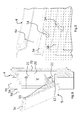
- said refrigerated compartment V is separate from the cell and is cooled by means of air channels 21, as will be discussed later on with reference to Fig. 8 .
- the compartment V further contains a tilting support shelf 11 and possibly also a bottle rack 10, which will be described with reference to Fig. 15 .
- the sectors 5a and 5b and the central wing 5c are provided with suitable sealing means, such as gaskets or the like.
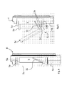
- Figs. 4, 5 and 6 there is shown the door 4 with the telescopic insert 5 viewed as a section in three different conditions: inserted ( Fig. 4 ), partially extracted ( Fig. 5 ), and fully extracted ( Fig. 6 ).
- telescopic insert 5 is in the inserted condition, with the telescopic sectors 5a, 5b inserted one into the other and the door 5c abutting against the frame 4a of the door 4.
- the refrigerated compartment V has the smallest volume.
- a tilting shelf 11 can be noticed, which can be used for supporting foodstuffs to be preserved.
- Said shelf 11 is hinged to the wing 5c by means of controlled horizontal-axis hinges, which allow the shelf 11 to fold towards the wing 5c or to arrange itself substantially perpendicularly thereto (as can be inferred by comparing Figs. 4 and 5 ).
- the shelf 11 When folded against the wing 5c, the shelf 11 can also arrange itself parallel to and/or leaning against the wing 5c, so as to take much less room.
- the shelf 11 is folded against the wing 5c in order to not require much room.
- the shelf 11 rotates and arranges itself perpendicularly to the wing 5c, ready for use.
- the tilting support shelf 11 is secured perpendicularly to the wing 5c, which is rotatable about a horizontal axis defined by the pins of the hinges 12: thus, when the wing 5c is brought into the open condition, as shown in Figs. 4 and 5 , the support shelf 11 will rotate integrally with the wing 5c to conveniently expose the foods or drinks contained therein to the user.
- a rack 10 coupled to the bottle shelf 11 is rotated integrally with the wing 5c to expose the bottles, which can then be comfortably picked up.
- Slide guides 14, visible in Fig. 7 are used for guiding the relative sliding motion between the telescopic sectors 5a and 5b, said guides being provided, for example, as a per se known coupling between a rail and a cavity, which will not be discussed any further.
- retaining means that limit the extraction travel of the telescopic insert 5: in this solution, said retaining means comprise housings containing balls 13a, which are held within the housing but can protrude outwards under the thrust of a spring, and a corresponding groove 13b for each ball.
- the frame 4a has one ball 13a to be coupled to, when the insert 5 is extracted, a seat 13b provided on the sector 5a; the latter also comprises one ball 13a to be coupled to a matching groove 13b provided on the sector 5b.
- Fig. 10 as an alternative to or in combination with the balls 13a and the respective grooves 13b, there are steps 13' protruding from each free edge of the sectors 5a and 5b and of the frame 4a, so that, when the sectors are in the extracted condition, the steps 13' abut against each other, thereby stopping the extraction movement of the telescopic insert 5.
- the steps 13' are provided with a perimetric rubber sealing lip or a gasket to ensure optimal airtightness, so as to prevent any cold air leaks and improve the thermal insulation.
- the telescopic insert 5 comprises converging sectors 5a' and 5b', i.e. with differently sized edges circumscribing the mouth and the rear opening; more in particular, the rear edge of the sector 5a', closest to the frame 4a, is bigger than the opening provided on the frame 4a itself, and the rear edge of the sector 5b' is bigger than the edge around the mouth of the sector 5a', so that, when the telescopic insert is extracted, its travel is stopped by the mutual interference between the parts, as shown in Fig. 11 .
- the volume of the refrigerated compartment V defined by the telescopic insert 5 is in fluidic communication with the cell C or with a cold air channel, so that the internal temperature can be kept at preferred food preservation levels.
- a wall 20 having at least one communication hole 21, preferably two holes, one for delivery and one for return, opening onto corresponding air channels provided on the door, behind the compartment V.
- the air channels run through the space 70, which in the operating condition is filled with a thermally insulating material, such as foam polyurethane or the like.
- the compartment V extends from the door 4 outside the cabinet 2, and therefore it is not a part of the cell contained in the latter.
- the compartment V defined by the door 4, the telescopic insert 5 and the wall 20 facing the wing 5c is associated with the door 4 and is closed, except for the communication hole(s) 21 for the air channels, resulting in the advantage that when the user opens said compartment V there are no significant cold air leaks from the cell, which in this case is only accessible by opening the door 4 by rotating it about a vertical axis.
- the user can decide to place bottles or foodstuffs into the compartment V of the door 4, equipped with the telescopic insert, so as to adapt the useful volume of the refrigerating appliance as a function of the contents thereof, thus wasting no energy to cool unused volumes of the appliance 1.
- said appliance 1 offers the advantage that it includes a rigid-sector telescopic insert 5, which improves the thermal insulation in comparison with a fabric-type or soft telescopic insert.
- the telescopic sectors 5a and 5b can be so designed as to include an insulation layer interposed at least between two perimetric walls.
- the sealing gaskets can be arranged in a more stable and secure way, with no risk of ineffective sealing: this is because they operate between rigid surfaces interfaced to each other.
- FIG. 15 there is shown a particularly advantageous solution for the shelf 11, which in this case also comprises a bottle rack element 10.
- Said rack element 10 can be engaged onto the shelf 11, e.g. by snapping thereon or by interference fit, so as to arrange itself at a certain distance from the shelf 11 and allow the assembly to support bottles or the like.
- the rack element 10 can be removed when the compartment V is smallest, i.e. when the telescopic insert 5 is fully inserted as in Fig. 4 .
- blowers and ducts fitted with shutter valves, operating to deliver into the compartment V a cold air flow taken, for example, from the refrigerated cells.
- Said ducts may be throttled to vary the quantity of cold air delivered into the compartment V, thus adjusting the temperature of the latter.
- a temperature sensor may optionally be employed to detect the temperature inside the compartment V, along with a control unit adapted to control the partialization of the cold air ducts in order to adjust the temperature and maintain it at values different from those of the refrigerated cells.
- the appliance 1 may comprise two cells, i.e. a refrigerator cell kept at a temperature between 3°C and 6°C, and a freezer cell kept at a temperature lower than -18°C, while the compartment V may be kept at a temperature around 12°C, which is optimal for wine preservation.
- the appliance 1 of the present invention advantageously includes a compartment where wine can be preserved at an optimal temperature, while still providing the usual refrigerator and freezer cells and offering high flexibility of use, also in terms of outside dimensions: in fact, if there are no wine bottles, the telescopic insert 5 can be fully inserted to attain a substantial advantage in terms of outside dimensions and energy consumption, since its volume will not have to be cooled.
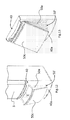
- FIGs. 12, 13 and 14 show a few solutions wherein the rigid-sector telescopic insert 5 is replaced by a soft extensible insert 50',50"'; in these drawings, the same reference numerals designate the same parts already discussed above and having the same functions, which will not therefore be described any further.
- Figs. 12 and 13 show the same extensible insert 50' in two different operating conditions: with the compartment open and closed, respectively.
- said extensible insert 50', 50"' does not offer the same advantages, in terms of strength and sealing, as those provided by the rigid-sector telescopic insert 5, it is however less expensive and lighter, so that it can be installed on low-end refrigerating appliances.
- the telescopic insert 5 comprises just two rigid telescopic sectors 5a and 5b, it may however comprise one, three, four or more rigid sectors, likewise connected to each other.
- both doors of the refrigerating appliance are designed as described above for the door 4.
- said expandable compartment is associated, as an alternative to or in combination with the one described above, with one of the side walls of the cabinet 2.
- the door 4 is slideably coupled to the cabinet 2; in this case, the refrigerated cell houses a drawer whose front portion is the door 4.
Landscapes
- Engineering & Computer Science (AREA)
- Chemical & Material Sciences (AREA)
- Combustion & Propulsion (AREA)
- Physics & Mathematics (AREA)
- Mechanical Engineering (AREA)
- Thermal Sciences (AREA)
- General Engineering & Computer Science (AREA)
- Devices That Are Associated With Refrigeration Equipment (AREA)
- Fire-Extinguishing Compositions (AREA)
Abstract
The present invention relates to a refrigerating appliance (1) comprising an insulated rigid cabinet (2), which internally houses at least one refrigerated cell accessible through a door (3,4), wherein at least one door (4) of said refrigerating appliance comprises a telescopic insert (5,50',50''50''') that at least partly defines an expandable-volume refrigerated compartment (V).
Description
- The present invention relates to an expandable refrigerating appliance.
- In this description and in the appended claims, the term "refrigerating appliance" refers to a refrigerator or a refrigerator-freezer, typically for domestic use, comprising one or more refrigerated cells which can be closed by a door and where foods and drinks to be preserved are placed.
- Changes in the people's habits have caused new needs to arise, which have also affected the field of household appliances, e.g. refrigerating appliances.
- For instance, now the people have less time to go shopping, so that they tend to accumulate large stocks of food which is then consumed a little at a time.
- This implies that they often prefer to buy high-capacity refrigerating appliances, which are filled up on just a few occasions, to be then progressively emptied.
- This results in some wasted energy, used for cooling very large refrigerated cells which are often not totally filled.
- More in particular, this problem arises when bottles or similar liquid containers are to be placed into the refrigerating appliance.
- In this case, in fact, the refrigerated cells normally include racks that keep the bottles in the vertical position and support them to prevent them from moving or falling when the doors are opened or closed.
- Such racks are usually arranged on the inner wall of the door of the refrigerating appliance, and their use is limited to bottles.
- In fact, in addition to having a predetermined size, said racks are also shaped in such a manner as to ensure optimum support for bottles only.
- It follows that the bottle space cannot be easily used for storing other foodstuffs having different shapes, resulting in some wasted room in the refrigerated cells.
- Of course, this problem gets even worse in the situations described above, when it is very important that the whole volume of the refrigerated cells is fully usable.
- The object of the present invention is to overcome this and other drawbacks.
- Said object is achieved through a refrigerating appliance as set forth in the appended
claim 1. The present invention is based on the idea of providing a telescopic insert in at least one door of the refrigerating appliance, so as to enlarge the refrigerated compartment defined by the door itself. - The volume of said compartment can thus be expanded, meaning that it can be enlarged or reduced according to the users' needs.
- Advantageously, the expandable-volume refrigerated compartment defined by the door fitted with such an insert may be separate from the actual refrigerated cells (e.g. it may just be in fluidic communication therewith), or said compartment may be a part of the refrigerated cell; in this latter case, the door and the telescopic insert will contribute to defining the walls of the refrigerated cell.
- Another advantageous feature relates to the fact that the door fitted with the telescopic insert can be opened by rotating it about a vertical axis, and a movable wing associated with the telescopic insert can be opened by rotating it about a horizontal axis: it is thus possible to open the wing without inadvertently opening the door as well.
- In a particular advantageous solution, the expandable-volume refrigerated compartment houses a swivelling rack and/or shelf for bottles or liquid container.
- These features as well as further advantages of the present invention will become more apparent from the following description of an embodiment thereof as shown in the annexed drawings, which are supplied by way of non-limiting example, wherein:
-
Figs. 1, 2 and 3 show a refrigerating appliance equipped with an expandable-volume refrigerated compartment according to the present invention, in three operating conditions; -
Figs. 4, 5 and6 are sectional views of the expandable-volume refrigerated compartment of the appliance ofFig. 1 , in three different operating conditions; -
Fig. 7 shows a detail of the slide guides; -
Fig. 8 is a sectional view of the expandable-volume refrigerated compartment in the configuration ofFig. 5 ; -
Fig. 9 shows in greater detail the guides ofFig. 7 ; -
Figs. 10 and 11 show two variants of the solution ofFigs. 4 and 5 ; -
Figs. 12, 13 and14 show different variants of the telescopic insert of the preceding figures; -
Fig. 15 shows a detail of a shelf that can be housed in the expandable volume of the refrigerating appliance ofFig. 1 . - Referring now to
Figs. 1-3 , there is shown a refrigerating appliance designated as a whole byreference numeral 1. - It comprises an insulated
rigid cabinet 2, wherein refrigerated cells are obtained which are accessible by opening thedoors - The
rigid cabinet 2 usually also contains all the functional components of theappliance 1, such as the compressor, any fans, the coolant ducts and the like. - The
doors - The
doors - In the example shown, in accordance with the teachings of the present invention, the
lower door 4 features a telescopic insert with rigid sectors, designated as a whole 5. - In this way, the volume of the refrigerated compartment V, partly defined by the
door 4, is made expandable, leading to increased flexibility of use of the refrigeratingappliance 1. - More in detail, it can be seen that the
door 4 comprises aframe 4a hinged to thecabinet 2 of theappliance 1, so that it can be rotated about a vertical hinge (not shown) to gain access to the refrigerated cell, much like a traditional unit. - The
door 4 also comprises, within theframe 4a, and substantially in a centred position, thetelescopic insert 5, which in turn comprises, in this example, tworigid sectors central wing 5c. - The two
sectors - In particular, it must be pointed out that the latter are rigid, e.g. made of plastic or metal, and have different dimensions, so that one can slide into the other.
- The
central wing 5c, which is also rigid and insulated like thesectors Fig. 3 , to allow access to the expandable-volume refrigerated compartment V. - Said
sectors central wing 5c are telescopically extractable, as shown inFigs. 1-3 , so as to advantageously enlarge or reduce the volume of the defined refrigerated compartment V according to the user's needs. - Therefore, the refrigerated compartment V thus defined by the
telescopic insert 5 features an expandable volume. - Said refrigerated compartment V may have different configurations with respect to the refrigerated cell (adjacent thereto and housed in the cabinet 2): completely separated from the cell, in fluidic communication with the cell, or substantially coinciding with the cell.
- In the first case, a wall having low thermal insulation is arranged between the volume of the expandable compartment and the adjacent refrigerated cell (preferably the freezer cell), so that the compartment V is indirectly cooled by the freezer compartment.
- As an alternative, heat exchangers may be installed in the compartment V in order to cool it.
- In the example shown, however, said refrigerated compartment V is separate from the cell and is cooled by means of
air channels 21, as will be discussed later on with reference toFig. 8 . - In the example shown, the compartment V further contains a
tilting support shelf 11 and possibly also abottle rack 10, which will be described with reference toFig. 15 . - In order to maintain the food preservation temperature and prevent any cold air leaks, the
sectors central wing 5c are provided with suitable sealing means, such as gaskets or the like. - Referring now to
Figs. 4, 5 and6 , there is shown thedoor 4 with thetelescopic insert 5 viewed as a section in three different conditions: inserted (Fig. 4 ), partially extracted (Fig. 5 ), and fully extracted (Fig. 6 ). - In
Fig. 4 , thetelescopic insert 5 is in the inserted condition, with thetelescopic sectors door 5c abutting against theframe 4a of thedoor 4. - In this condition, the refrigerated compartment V has the smallest volume.
- Inside the compartment V a tilting
shelf 11 can be noticed, which can be used for supporting foodstuffs to be preserved. - Said
shelf 11 is hinged to thewing 5c by means of controlled horizontal-axis hinges, which allow theshelf 11 to fold towards thewing 5c or to arrange itself substantially perpendicularly thereto (as can be inferred by comparingFigs. 4 and 5 ). - When folded against the
wing 5c, theshelf 11 can also arrange itself parallel to and/or leaning against thewing 5c, so as to take much less room. - When the telescopic insert is inserted, the
shelf 11 is folded against thewing 5c in order to not require much room. - When the
telescopic insert 5 is extracted, as shown inFig. 5 , theshelf 11 rotates and arranges itself perpendicularly to thewing 5c, ready for use. - It should be noted that the controlled hinge that couples the
shelf 11 to thewing 5c is secured to the latter, with the result that, when the wing is rotated about its horizontal-axis hinge 12 that couples it to theframe 4a, the shelf will rotate accordingly as well. - As can be seen in these drawings, the
tilting support shelf 11 is secured perpendicularly to thewing 5c, which is rotatable about a horizontal axis defined by the pins of the hinges 12: thus, when thewing 5c is brought into the open condition, as shown inFigs. 4 and 5 , thesupport shelf 11 will rotate integrally with thewing 5c to conveniently expose the foods or drinks contained therein to the user. - Likewise, a
rack 10 coupled to thebottle shelf 11 is rotated integrally with thewing 5c to expose the bottles, which can then be comfortably picked up. -
Slide guides 14, visible inFig. 7 , are used for guiding the relative sliding motion between thetelescopic sectors - The
guides 14, also visible in the detail ofFig. 9 , allow the twosectors first sector 5a to translate relative to theframe 4a, and thesecond sector 5b to translate relative to thefirst sector 5a. - Referring back to
Figs. 4, 5 and6 , they also show the retaining means that limit the extraction travel of the telescopic insert 5: in this solution, said retaining means comprisehousings containing balls 13a, which are held within the housing but can protrude outwards under the thrust of a spring, and acorresponding groove 13b for each ball. - More in particular, the
frame 4a has oneball 13a to be coupled to, when theinsert 5 is extracted, aseat 13b provided on thesector 5a; the latter also comprises oneball 13a to be coupled to amatching groove 13b provided on thesector 5b. - In practice, when the
telescopic insert 5 is extracted, as inFig. 5 , theballs 13a, pushed outwards by the springs, meet thegrooves 13b and settle therein, thereby stopping the sliding insert. When thetelescopic insert 5 is inserted (as inFig. 4 ), theballs 13a are pushed into their housing again, thus compressing the springs; the movement of the insert stops when the various parts abut on each other. - A few alternatives for these retaining means are shown in
Figs. 10 and 11 . - In
Fig. 10 , as an alternative to or in combination with theballs 13a and therespective grooves 13b, there are steps 13' protruding from each free edge of thesectors frame 4a, so that, when the sectors are in the extracted condition, the steps 13' abut against each other, thereby stopping the extraction movement of thetelescopic insert 5. - Advantageously, the steps 13' are provided with a perimetric rubber sealing lip or a gasket to ensure optimal airtightness, so as to prevent any cold air leaks and improve the thermal insulation.
- In another variant shown in
Fig. 11 , thetelescopic insert 5 comprises convergingsectors 5a' and 5b', i.e. with differently sized edges circumscribing the mouth and the rear opening; more in particular, the rear edge of thesector 5a', closest to theframe 4a, is bigger than the opening provided on theframe 4a itself, and the rear edge of thesector 5b' is bigger than the edge around the mouth of thesector 5a', so that, when the telescopic insert is extracted, its travel is stopped by the mutual interference between the parts, as shown inFig. 11 . - The volume of the refrigerated compartment V defined by the
telescopic insert 5 is in fluidic communication with the cell C or with a cold air channel, so that the internal temperature can be kept at preferred food preservation levels. - This can be attained by not fitting a dividing septum between the cell and the
telescopic insert 5, or thedoor 4; in this case, the volume of the compartment V extends inside thecabinet 2 and is a part of the cell of theappliance 1. - Alternatively, as shown in
Fig. 8 in the present example, it is conceivable to provide awall 20 having at least onecommunication hole 21, preferably two holes, one for delivery and one for return, opening onto corresponding air channels provided on the door, behind the compartment V. - The air channels run through the
space 70, which in the operating condition is filled with a thermally insulating material, such as foam polyurethane or the like. - In this condition, the compartment V extends from the
door 4 outside thecabinet 2, and therefore it is not a part of the cell contained in the latter. - In practice, in this solution the compartment V defined by the
door 4, thetelescopic insert 5 and thewall 20 facing thewing 5c is associated with thedoor 4 and is closed, except for the communication hole(s) 21 for the air channels, resulting in the advantage that when the user opens said compartment V there are no significant cold air leaks from the cell, which in this case is only accessible by opening thedoor 4 by rotating it about a vertical axis. - It can therefore be easily understood from the above description that this solution ensures an extremely versatile use of the refrigerating appliance.
- In fact, the user can decide to place bottles or foodstuffs into the compartment V of the
door 4, equipped with the telescopic insert, so as to adapt the useful volume of the refrigerating appliance as a function of the contents thereof, thus wasting no energy to cool unused volumes of theappliance 1. - Furthermore, said
appliance 1 offers the advantage that it includes a rigid-sectortelescopic insert 5, which improves the thermal insulation in comparison with a fabric-type or soft telescopic insert. - In this respect, it must be pointed out that the
telescopic sectors rigid sectors - Referring to
Fig. 15 , there is shown a particularly advantageous solution for theshelf 11, which in this case also comprises abottle rack element 10. - Said
rack element 10 can be engaged onto theshelf 11, e.g. by snapping thereon or by interference fit, so as to arrange itself at a certain distance from theshelf 11 and allow the assembly to support bottles or the like. - Of course, the
rack element 10 can be removed when the compartment V is smallest, i.e. when thetelescopic insert 5 is fully inserted as inFig. 4 . - As for controlling the cooling of the compartment V, different solutions may be adopted when it is separate from the refrigerated cell and when air channels and holes 21 are provided.
- For example, there may be blowers and ducts fitted with shutter valves, operating to deliver into the compartment V a cold air flow taken, for example, from the refrigerated cells.
- Said ducts may be throttled to vary the quantity of cold air delivered into the compartment V, thus adjusting the temperature of the latter.
- In this case, a temperature sensor may optionally be employed to detect the temperature inside the compartment V, along with a control unit adapted to control the partialization of the cold air ducts in order to adjust the temperature and maintain it at values different from those of the refrigerated cells.
- For example, with advantages in terms of flexibility of use, the
appliance 1 may comprise two cells, i.e. a refrigerator cell kept at a temperature between 3°C and 6°C, and a freezer cell kept at a temperature lower than -18°C, while the compartment V may be kept at a temperature around 12°C, which is optimal for wine preservation. - Thus, the
appliance 1 of the present invention advantageously includes a compartment where wine can be preserved at an optimal temperature, while still providing the usual refrigerator and freezer cells and offering high flexibility of use, also in terms of outside dimensions: in fact, if there are no wine bottles, thetelescopic insert 5 can be fully inserted to attain a substantial advantage in terms of outside dimensions and energy consumption, since its volume will not have to be cooled. - Of course, many variations of the invention as described above may be conceived by those skilled in the art.
- For example,
Figs. 12, 13 and14 show a few solutions wherein the rigid-sectortelescopic insert 5 is replaced by a softextensible insert 50',50"'; in these drawings, the same reference numerals designate the same parts already discussed above and having the same functions, which will not therefore be described any further. -
Figs. 12 and 13 show the same extensible insert 50' in two different operating conditions: with the compartment open and closed, respectively. - Although in principle said
extensible insert 50', 50"' does not offer the same advantages, in terms of strength and sealing, as those provided by the rigid-sectortelescopic insert 5, it is however less expensive and lighter, so that it can be installed on low-end refrigerating appliances. - Also, although in the example described so far the
telescopic insert 5 comprises just two rigidtelescopic sectors - According to further variants, both doors of the refrigerating appliance are designed as described above for the
door 4. - In other solutions there are three or more doors, at least one of which is designed in accordance with the teachings of the present invention.
- According to further variants, said expandable compartment is associated, as an alternative to or in combination with the one described above, with one of the side walls of the
cabinet 2. - In another alternative solution, the
door 4 is slideably coupled to thecabinet 2; in this case, the refrigerated cell houses a drawer whose front portion is thedoor 4.
Claims (12)
- A refrigerating appliance (1) comprising an insulated rigid cabinet (2) which internally houses at least one refrigerated cell accessible through a door (3,4),
characterized in that
at least one door (4) of said refrigerating appliance comprises a telescopic insert (5,50',50''') that at least partly defines an expandable-volume refrigerated compartment (V). - A refrigerating appliance (1) according to claim 1, wherein said door (4) comprises a frame (4a) coupled to said cabinet (2), said telescopic insert (5,50',50"') being secured to said frame (4a), and wherein said door (4) also comprises a wing (5c) hinged to said telescopic insert (5,50',50"') to allow access to said expandable-volume refrigerated compartment (V).
- A refrigerating appliance (1) according to claim 1 or 2, wherein said door (4) is rotatable about a vertical axis to allow access to said refrigerated cell.
- A refrigerating appliance (1) according to claim 1 or 2, wherein said door (4) is linearly slideable relative to said cabinet (2).
- A refrigerating appliance (1) according to one of claims 1 to 4, wherein said wing (5c) is hinged to said telescopic insert (5,50',50''') by means of horizontal-axis hinges (12).
- A refrigerating appliance (1) according to one or more of claims 1 to 5, wherein said telescopic insert (5) comprises at least one rigid telescopic sector (5a,5b,5a',5b') which is linearly movable relative to said frame (4a).
- A refrigerating appliance (1) according to one or more of claims 1 to 6, wherein said expandable-volume refrigerated compartment (V) contains a tilting support shelf (11) preferably hinged to said wing (5c) through controlled horizontal-axis hinges to allow said shelf (11) to either fold towards the wing (5c) or to arrange itself substantially perpendicular thereto.
- A refrigerating appliance (1) according to one or more of claims 1 to 7, wherein said telescopic insert (5) comprises retaining means (13a,13b,13') which stop its movement when it is extracted.
- A refrigerating appliance (1) according to claim 8, wherein said retaining means comprise steps (13') and sealing means, such as sealing lips, gaskets or the like.
- A refrigerating appliance (1) according to one or more of claims 1 to 9, wherein said expandable-volume refrigerated compartment (V) is in fluidic communication with at least one cold air channel (21).
- A refrigerating appliance (1) according to one or more of claims 1 to 9, wherein said expandable-volume refrigerated compartment (V) is defined by at least one wall having low thermal insulation arranged between said compartment (V) and a refrigerated cell adjacent thereto, thus cooling said compartment (V).
- A refrigerating appliance (1) according to claim 10, comprising means for generating a cold air flow and ducts for conveying said cold air towards said expandable-volume refrigerated compartment (V), and wherein said expandable-volume refrigerated compartment (V) is preferably kept at a desired temperature by means of a variable flow of cold air taken from said refrigerated cell.
Applications Claiming Priority (1)
| Application Number | Priority Date | Filing Date | Title |
|---|---|---|---|
| IT000556A ITTO20100556A1 (en) | 2010-06-29 | 2010-06-29 | EXPANDABLE REFRIGERATION APPLIANCE |
Publications (1)
| Publication Number | Publication Date |
|---|---|
| EP2402688A1 true EP2402688A1 (en) | 2012-01-04 |
Family
ID=43446718
Family Applications (1)
| Application Number | Title | Priority Date | Filing Date |
|---|---|---|---|
| EP11171554A Withdrawn EP2402688A1 (en) | 2010-06-29 | 2011-06-27 | Expandable refrigerating appliance |
Country Status (2)
| Country | Link |
|---|---|
| EP (1) | EP2402688A1 (en) |
| IT (1) | ITTO20100556A1 (en) |
Cited By (2)
| Publication number | Priority date | Publication date | Assignee | Title |
|---|---|---|---|---|
| US9841223B2 (en) | 2014-12-01 | 2017-12-12 | Samsung Electronics Co., Ltd. | Refrigerator |
| EP3431907A1 (en) * | 2017-07-20 | 2019-01-23 | Vestel Elektronik Sanayi ve Ticaret A.S. | Apparatus for storing consumables |
Citations (4)
| Publication number | Priority date | Publication date | Assignee | Title |
|---|---|---|---|---|
| US2713776A (en) * | 1954-03-15 | 1955-07-26 | Philco Corp | Refrigerators |
| JPH02133782A (en) * | 1988-11-14 | 1990-05-22 | Sanden Corp | Home delivery item receiving box with cooling device |
| WO2006067505A1 (en) * | 2004-12-23 | 2006-06-29 | Chris Piponides | Extendible refrigerator/appliance |
| WO2007095779A1 (en) * | 2006-02-27 | 2007-08-30 | Qingyang Zhang | Telescopic refrigerator |
-
2010
- 2010-06-29 IT IT000556A patent/ITTO20100556A1/en unknown
-
2011
- 2011-06-27 EP EP11171554A patent/EP2402688A1/en not_active Withdrawn
Patent Citations (4)
| Publication number | Priority date | Publication date | Assignee | Title |
|---|---|---|---|---|
| US2713776A (en) * | 1954-03-15 | 1955-07-26 | Philco Corp | Refrigerators |
| JPH02133782A (en) * | 1988-11-14 | 1990-05-22 | Sanden Corp | Home delivery item receiving box with cooling device |
| WO2006067505A1 (en) * | 2004-12-23 | 2006-06-29 | Chris Piponides | Extendible refrigerator/appliance |
| WO2007095779A1 (en) * | 2006-02-27 | 2007-08-30 | Qingyang Zhang | Telescopic refrigerator |
Cited By (2)
| Publication number | Priority date | Publication date | Assignee | Title |
|---|---|---|---|---|
| US9841223B2 (en) | 2014-12-01 | 2017-12-12 | Samsung Electronics Co., Ltd. | Refrigerator |
| EP3431907A1 (en) * | 2017-07-20 | 2019-01-23 | Vestel Elektronik Sanayi ve Ticaret A.S. | Apparatus for storing consumables |
Also Published As
| Publication number | Publication date |
|---|---|
| ITTO20100556A1 (en) | 2011-12-30 |
Similar Documents
| Publication | Publication Date | Title |
|---|---|---|
| US9945602B2 (en) | Appliance modular system for incorporating a pantry compartment within an appliance | |
| US8424985B2 (en) | Refrigerator with a door-in-door | |
| US9127877B2 (en) | Refrigerator | |
| CN102478343B (en) | Refrigerator and container assemblies thereof | |
| EP2438374B1 (en) | Refrigerator | |
| EP2937651B1 (en) | Refrigerator | |
| CN105716353B (en) | Air duct assembly for air-cooled refrigerator and air-cooled refrigerator | |
| US9115924B2 (en) | In-the-door cooling system for domestic refrigerators | |
| CN101821571B (en) | Refrigerator | |
| US10006693B2 (en) | Appliance modular system for incorporating a pantry compartment within an appliance | |
| US20120181910A1 (en) | Refrigerator with drawer type door | |
| US20170167780A1 (en) | Refrigerator | |
| EP3228968A1 (en) | Refrigerator | |
| EP2336691A1 (en) | Refrigerating appliance | |
| US20200173713A1 (en) | Refrigerator | |
| WO2018121664A1 (en) | Refrigerator | |
| CN106766488B (en) | Air-cooled refrigerator and control method thereof | |
| KR20150084265A (en) | Filler appparatus for refrigerator | |
| EP4006457B1 (en) | Refrigerator capable of improving air circulation in machine chamber | |
| JP6767615B2 (en) | refrigerator | |
| US20190360741A1 (en) | Refrigerator appliance with multiple zone flexible chamber in door | |
| KR20160095919A (en) | Refrigerator of cold air inlet gasket | |
| WO2007010267A2 (en) | Improvements in or relating to cold storage | |
| US11391507B2 (en) | Refrigerator appliance with articulating horizontal mullion | |
| ITTO20100556A1 (en) | EXPANDABLE REFRIGERATION APPLIANCE |
Legal Events
| Date | Code | Title | Description |
|---|---|---|---|
| AK | Designated contracting states |
Kind code of ref document: A1 Designated state(s): AL AT BE BG CH CY CZ DE DK EE ES FI FR GB GR HR HU IE IS IT LI LT LU LV MC MK MT NL NO PL PT RO RS SE SI SK SM TR |
|
| AX | Request for extension of the european patent |
Extension state: BA ME |
|
| PUAI | Public reference made under article 153(3) epc to a published international application that has entered the european phase |
Free format text: ORIGINAL CODE: 0009012 |
|
| 17P | Request for examination filed |
Effective date: 20120703 |
|
| STAA | Information on the status of an ep patent application or granted ep patent |
Free format text: STATUS: THE APPLICATION IS DEEMED TO BE WITHDRAWN |
|
| 18D | Application deemed to be withdrawn |
Effective date: 20140102 |