EP2402654A1 - Gas stove - Google Patents
Gas stove Download PDFInfo
- Publication number
- EP2402654A1 EP2402654A1 EP10006526A EP10006526A EP2402654A1 EP 2402654 A1 EP2402654 A1 EP 2402654A1 EP 10006526 A EP10006526 A EP 10006526A EP 10006526 A EP10006526 A EP 10006526A EP 2402654 A1 EP2402654 A1 EP 2402654A1
- Authority
- EP
- European Patent Office
- Prior art keywords
- gas
- flame ports
- burner
- mixing zone
- upper cap
- Prior art date
- Legal status (The legal status is an assumption and is not a legal conclusion. Google has not performed a legal analysis and makes no representation as to the accuracy of the status listed.)
- Granted
Links
Images

Classifications
-
- F—MECHANICAL ENGINEERING; LIGHTING; HEATING; WEAPONS; BLASTING
- F24—HEATING; RANGES; VENTILATING
- F24C—DOMESTIC STOVES OR RANGES ; DETAILS OF DOMESTIC STOVES OR RANGES, OF GENERAL APPLICATION
- F24C3/00—Stoves or ranges for gaseous fuels
- F24C3/08—Arrangement or mounting of burners
- F24C3/085—Arrangement or mounting of burners on ranges
-
- F—MECHANICAL ENGINEERING; LIGHTING; HEATING; WEAPONS; BLASTING
- F23—COMBUSTION APPARATUS; COMBUSTION PROCESSES
- F23D—BURNERS
- F23D14/00—Burners for combustion of a gas, e.g. of a gas stored under pressure as a liquid
- F23D14/02—Premix gas burners, i.e. in which gaseous fuel is mixed with combustion air upstream of the combustion zone
- F23D14/04—Premix gas burners, i.e. in which gaseous fuel is mixed with combustion air upstream of the combustion zone induction type, e.g. Bunsen burner
- F23D14/06—Premix gas burners, i.e. in which gaseous fuel is mixed with combustion air upstream of the combustion zone induction type, e.g. Bunsen burner with radial outlets at the burner head
-
- F—MECHANICAL ENGINEERING; LIGHTING; HEATING; WEAPONS; BLASTING
- F23—COMBUSTION APPARATUS; COMBUSTION PROCESSES
- F23D—BURNERS
- F23D14/00—Burners for combustion of a gas, e.g. of a gas stored under pressure as a liquid
- F23D14/46—Details
- F23D14/48—Nozzles
- F23D14/58—Nozzles characterised by the shape or arrangement of the outlet or outlets from the nozzle, e.g. of annular configuration
Definitions
- the present invention relates to a gas stove having an upper work plate with at least one integrated gas burner, said gas burner comprising a bowl-shaped base body, a burner crown arranged on the base body, and an upper cap arranged on the burner crown, wherein several flame ports are provided to let out a gas-air mixture towards a recipient to be heated, and wherein an annular mixing zone, whose cross section incrementally expands towards the flame ports, is defined between the burner crown and the upper cap.
- a gas stove of the above-mentioned kind is known for example from EP-A-1 898 153 .
- This gas stove comprises one or more gas burners, each being formed by a bowl-shaped base body, a burner crown arranged on the base body, and an upper cap arranged on the burner crown.
- the burner crown is provided on its circumference with a plurality of flame ports to let the gas-air-mixture go out in a radial direction and essentially in parallel to the bottom of the recipient to be heated.
- the upper cap closes the burner top and defines the flame ports together with the burner crown.
- An annular mixing zone is provided between the burner crown and the upper cap. The cross section of the mixing zone incrementally expands towards the flame ports.
- the mixing zone is defined by a planar horizontal bottom side of the upper cap and by an annular recess formed at the top side of the burner crown, wherein the depth of the annular recess incrementally increases in a radial direction towards the flame ports.
- One major drawback of the described gas burner construction is that a lot of heat is released to the environment by the flames produced by such flame ports letting the gas-air-mixture go out in a radial direction. Accordingly, the efficiency of the gas burner is low. Moreover, the heat released to the environment may negatively effect the lifetime of the appliance or the colour of the work plate to which the gas burner is fixed, or the like.
- the present invention provides a gas burner of the above-mentioned kind, which is characterized in that the burner crown is provided with a Venturi pipe, which feeds the gas-air mixture into the mixing zone and is designed to suck primary air from above the upper work plate, in that the flame ports are formed in the upper cap as through-holes, and in that the bottom side of the upper cap, which defines the upper side of the mixing zone, is at least partially inclined upwardly towards the flame ports with respect to the horizontal in order to define the incrementally expanding cross section of the mixing zone.
- the flame ports are formed as through-holes provided in the upper cap, the gas-air-mixture or rather the flames leave the flame ports in an upward direction directly towards the recipient to be heated. Accordingly, only very few heat is released to the environment such that no derogations of the lifetime or the appearance of the appliance are to be expected. Moreover, due to the little heat loss the efficiency of the burner is high. Furthermore, the flame ports are oriented towards the upcoming flow of the gas-air mixture, whereby turbulences within the mixing zone are at least partially prevented.
- the provision of the flame ports in the upper cap leads to a shortening of the distance between the flame ports an the recipient to be heated and thus to a reduction of the length of the flames compared to the design, where the flame ports are arranged sideways at the circumference of the burner crown. As a consequence, the amount of secondary air entrained by the flames is substantially reduced, compromising the combustion results.
- the present invention counters the lack of secondary air with an increased amount of primary air, recovering the combustion performances.
- This increased amount of primary air is gained by means of a special design of the mixing zone, where the bottom side of the upper cap, which defines the upper side of the mixing zone, is at least partially inclined upwardly towards the flame ports with respect to the horizontal in order to define the incrementally expanding cross section of the mixing zone.
- This design achieves a very good primary air entrainment, because the creation of unnecessary turbulences in the flame ports is further eliminated due to the fact that the design of the mixing zone is adjusted to the flow direction of the incoming gas-air mixture.
- the primary air is sucked from above the upper work plate. Therefore, an endless reservoir of primary air is available.
- the upper side of the burner crown which defines the bottom side of the mixing zone, extends with a maximum angle of 10° with respect to the horizontal. In this manner an optimal adjustment of the mixing zone with respect to the flow direction of the incoming gas-air mixture can be achieved.
- the bottom side of the upper cap is formed with an annular recess whose depth increases in a radial direction towards the flame ports.
- the flame ports are inclined with respect to the vertical by an angle of at least 15°, preferably by an angle of about 45°. This also contributes to a reduction of turbulences in the flame ports and thus to a good primary air entrainment.
- the flame ports extend at right angle from a surface of the annular recess provided at the bottom side of the upper cap. Accordingly, the drilling process for producing the through-holes is simplified since now an orthogonal surface is provided for positioning the drilling tool. This enhances the quality of the drilling operations and reduces the operational time as well as the scrap.
- the inclination of the flame ports is essentially aligned with the flow direction of the gas-air mixture directly ahead of the flame ports, i.e. immediately before the gas-air mixture enters the flame ports. This also contributes to the prevention of turbulences within the mixing zone.
- the Venturi pipe is designed to suck primary exclusively from above the upper work plate. With this design very good results were achieved.
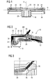
- FIGS 1 to 3 show components of a gas stove 10 according to an embodiment of the present invention.
- the gas stove 10 has an upper work plate 12 with an integrated gas burner 14.
- the gas burner 14 comprises a bowl-shaped base body 16, which is not shown in further detail, a burner crown 18 arranged on the base body 16, and an upper cap 20 arranged on the burner crown 18.
- the base body 16 of the gas burner 14 is received in the upper work plate 12 of the gas stove 10 and comprises in its lower portion an injector 22, which is connected to a gas supplying pipe.
- the injector 22 projects into a chamber 24, which is defined between the base body 16 and the burner crown 18 and which is provided with several inlets 26 through which ambient air from above the upper work plate 12 is entrained into the chamber 24 as primary air 25.
- the burner crown 18, which is arranged on top of the bowl-shaped base body 16, comprises a Venturi pipe 28, which projects into the chamber 24 and is positioned vertically above the injector 22.
- the Venturi pipe 28 leads into an annular mixing zone 30, which is formed between the burner crown 18 and the upper cap 20 and whose cross section or perimeter section expands radially outwards from the Venturi pipe 28.
- the upper cap 20 is formed at its bottom side with an annular recess 32, whose main surface 33 is upwardly inclined with respect to the horizontal H such that the depth of the recess 32 incrementally increases radially outwards in order to create the incrementally outwards expanding cross section of the mixing zone 30.
- the upper surface of the burner crown 18 extends with a maximum angle of 10° with respect to the horizontal H.
- the upper cap 20 is provided with a plurality of flame ports 34, which are inclined with respect to the vertical V by an angle of at least 30°, preferably about 45°.
- the flame ports 34 are annularly arranged, whereas each flame port 34 is provided as a though-hole leading from the mixing zone 30 to the upper side of the upper cap 20.
- the surface 36 of the annular recess 32, from which the flame ports 34 extend, is arranged at right angle with respect to the flame ports 34. Accordingly, the drilling process for producing the through-holes is simplified since an orthogonal surface is provided for positioning the drilling tool. This enhances the quality of the drilling operations and reduces the operational time as well as the scrap.
- the gas is supplied to the injector 22 through a gas supplying pipe.
- the injector 22 injects the gas into the mixing zone 30 via the chamber 24 and the Venturi pipe 28.
- Within the chamber 24 ambient air is sucked as primary air 25 exclusively from above the upper work plate 12 through the inlets 26 and then flows through the Venturi pipe 28 into the mixing zone 30, where the gas-air-mixture is mixed.
- Due to the incrementally expanding cross section of the mixing zone 30, the pressure of the gas-air mixture is increased and its velocity is reduced until the gas-air-mixture reaches the flame ports 34.
- the gas-air-mixture leaves the gas burner 14 through the flame ports 34.
- the flames 38 which are created above the flame ports 34 and are directed towards the recipient to be heated, entrain secondary air 39.
- the flame ports 34 are directed towards the recipient to be heated, most of the heat is transferred to the recipient. Thus, the efficiency of the gas burner 14 is very high. Furthermore, very little heat is released into the environment. Accordingly, no damage of other components, such as a degradation of the colour of the upper work plate 12 of the gas stove 10, is to be expected. Furthermore, since the flame ports 34 are inclined with respect to the vertical V by an angle of at least 30°, perferably about 45°, they are aligned with the flow direction of the gas-air mixture directly ahead of the flame ports 34, such that the discharge of the gas-air mixture in the environment is facilitated. This leads to an improvement of the fluid dynamics of the burner14.
- the designs of the mixing zone 30 and of the flame ports 34 are optimally adjusted to the flow direction of the gas-air mixture entering the mixing-zone 30. Accordingly, turbulences within the mixing zone 30 are prevented and a very good primary air entertainment is achieved.
- a comparative example of a gas stove 100 is shown throughout figures 4 to 6 .
- the gas stove 100 has an upper work plate 102 with an integrated gas burner 104.
- the gas burner 104 comprises a bowl-shaped base body 106, a burner crown 108 arranged on the base body 106, and an upper cap 110 arranged on the burner crown 108.
- the base body 106 of the gas burner 104 is received in the upper work plate 102 of the gas stove 100 and comprises in its lower portion an injector 112, which is connected to a gas supplying pipe.
- the injector 112 projects into a chamber 114, which is defined between the base body 106 and the burner crown 108 and which is provided with several inlets 116 through which ambient air from above the upper work plate 102 is supplied into the chamber 114 as primary air 115.
- the burner crown 108 which is arranged on top of the bowl-shaped base body 106, comprises a Venturi pipe 118, which projects into the chamber 114 and is positioned vertically above the injector 112.
- the Venturi pipe 118 leads into an annular mixing zone 120, which is formed between the burner crown 108 and the upper cap 110 and whose cross section or perimeter section expands radially outwards from the Venturi pipe 118.
- the burner crown 108 is formed at its upper side with an annular recess 122, whose depth incrementally increases radially outwards in order to create the incrementally outwards expanding cross section of the mixing zone 120.
- the mixing zone 120 passes into a steady zone 121, which is defined by the burner crown 108 and the upper cap 110 and has a constant cross section or perimeter section in the radial direction.
- the upper cap 110 has a planar bottom side. In the area of its outer diameter the upper cap 110 is provided with a plurality of annularly arranged flame ports 124, which are slanted with respect to the vertical by an angle of at least 30°, preferably about 45°.
- the flame ports 124 are formed as though-holes leading from the steady zone 121 to the upper side of the upper cap 110.
- the gas is supplied to the injector 112 through a gas supplying pipe.
- the injector 112 injects the gas into the mixing zone 120 via the chamber 114 and the Venturi pipe 118.
- the ambient air is sucked as primary air 115 from above the upper work plate 102 through the inlets 116 and then flows through the Venturi pipe 118 into the mixing zone 120, where the gas-air-mixture is mixed.
- Due to the incrementally expanding cross section of the mixing zone 120 the pressure and the velocity of the gas-air-mixture are reduced until the gas-air-mixture reaches the steady zone 121.
- Within the steady zone 121 the pressure and the velocity of the gas-air mixture are kept constant in order to distribute the mixture evenly across the flame ports 124.
- the gas-air-mixture leaves the gas burner 104 through the flame ports 124.
Landscapes
- Engineering & Computer Science (AREA)
- Chemical & Material Sciences (AREA)
- Combustion & Propulsion (AREA)
- Mechanical Engineering (AREA)
- General Engineering & Computer Science (AREA)
- Gas Burners (AREA)
Abstract
Description
- The present invention relates to a gas stove having an upper work plate with at least one integrated gas burner, said gas burner comprising a bowl-shaped base body, a burner crown arranged on the base body, and an upper cap arranged on the burner crown, wherein several flame ports are provided to let out a gas-air mixture towards a recipient to be heated, and wherein an annular mixing zone, whose cross section incrementally expands towards the flame ports, is defined between the burner crown and the upper cap.
- A gas stove of the above-mentioned kind is known for example from
EP-A-1 898 153 . This gas stove comprises one or more gas burners, each being formed by a bowl-shaped base body, a burner crown arranged on the base body, and an upper cap arranged on the burner crown. The burner crown is provided on its circumference with a plurality of flame ports to let the gas-air-mixture go out in a radial direction and essentially in parallel to the bottom of the recipient to be heated. The upper cap closes the burner top and defines the flame ports together with the burner crown. An annular mixing zone is provided between the burner crown and the upper cap. The cross section of the mixing zone incrementally expands towards the flame ports. The mixing zone is defined by a planar horizontal bottom side of the upper cap and by an annular recess formed at the top side of the burner crown, wherein the depth of the annular recess incrementally increases in a radial direction towards the flame ports. - One major drawback of the described gas burner construction is that a lot of heat is released to the environment by the flames produced by such flame ports letting the gas-air-mixture go out in a radial direction. Accordingly, the efficiency of the gas burner is low. Moreover, the heat released to the environment may negatively effect the lifetime of the appliance or the colour of the work plate to which the gas burner is fixed, or the like.
- It is an object of the present invention to provide a gas stove equipped with the gas burner of the above-mentioned kind with a good efficiency. Moreover, it is an object of the present invention to provide a gas burner of the above-mentioned kind, whose flames do not negatively effect the lifetime or the appearance of the appliance. Furthermore, an adequate air entrainment is to be assured.
- In order to solve this object the present invention provides a gas burner of the above-mentioned kind, which is characterized in that the burner crown is provided with a Venturi pipe, which feeds the gas-air mixture into the mixing zone and is designed to suck primary air from above the upper work plate, in that the flame ports are formed in the upper cap as through-holes, and in that the bottom side of the upper cap, which defines the upper side of the mixing zone, is at least partially inclined upwardly towards the flame ports with respect to the horizontal in order to define the incrementally expanding cross section of the mixing zone.
- Due to the fact that the flame ports are formed as through-holes provided in the upper cap, the gas-air-mixture or rather the flames leave the flame ports in an upward direction directly towards the recipient to be heated. Accordingly, only very few heat is released to the environment such that no derogations of the lifetime or the appearance of the appliance are to be expected. Moreover, due to the little heat loss the efficiency of the burner is high. Furthermore, the flame ports are oriented towards the upcoming flow of the gas-air mixture, whereby turbulences within the mixing zone are at least partially prevented.
- However, applicants have recognized, that the provision of the flame ports in the upper cap leads to a shortening of the distance between the flame ports an the recipient to be heated and thus to a reduction of the length of the flames compared to the design, where the flame ports are arranged sideways at the circumference of the burner crown. As a consequence, the amount of secondary air entrained by the flames is substantially reduced, compromising the combustion results.
- The most obvious solution to counter this lack of secondary air would be to increase the distance between the burner and the recipient to be heated. However, this would at least partially jeopardize the improved thermal efficiency mentioned before.
- Therefore, the present invention counters the lack of secondary air with an increased amount of primary air, recovering the combustion performances. This increased amount of primary air is gained by means of a special design of the mixing zone, where the bottom side of the upper cap, which defines the upper side of the mixing zone, is at least partially inclined upwardly towards the flame ports with respect to the horizontal in order to define the incrementally expanding cross section of the mixing zone. This design achieves a very good primary air entrainment, because the creation of unnecessary turbulences in the flame ports is further eliminated due to the fact that the design of the mixing zone is adjusted to the flow direction of the incoming gas-air mixture. Moreover, the primary air is sucked from above the upper work plate. Therefore, an endless reservoir of primary air is available.
- Preferably, the upper side of the burner crown, which defines the bottom side of the mixing zone, extends with a maximum angle of 10° with respect to the horizontal. In this manner an optimal adjustment of the mixing zone with respect to the flow direction of the incoming gas-air mixture can be achieved.
- According to one aspect of the present invention, the bottom side of the upper cap is formed with an annular recess whose depth increases in a radial direction towards the flame ports.
- According to a further aspect of the present invention the flame ports are inclined with respect to the vertical by an angle of at least 15°, preferably by an angle of about 45°. This also contributes to a reduction of turbulences in the flame ports and thus to a good primary air entrainment.
- Preferably, the flame ports extend at right angle from a surface of the annular recess provided at the bottom side of the upper cap. Accordingly, the drilling process for producing the through-holes is simplified since now an orthogonal surface is provided for positioning the drilling tool. This enhances the quality of the drilling operations and reduces the operational time as well as the scrap.
- Advantageously, the inclination of the flame ports is essentially aligned with the flow direction of the gas-air mixture directly ahead of the flame ports, i.e. immediately before the gas-air mixture enters the flame ports. This also contributes to the prevention of turbulences within the mixing zone.
- According to one aspect of the present invention the Venturi pipe is designed to suck primary exclusively from above the upper work plate. With this design very good results were achieved.
- Further features and advantages of the present invention will become apparent by means of the following description of a preferred embodiment of an inventive gas stove with reference to the accompanying drawing. In the drawing
- Figure 1
- is a cross section view of a burner crown and an upper cap of gas burner of gas stove according to an embodiment of the present invention;
- Figure 2
- is a schematic view of the arrangement shown in
figure 1 , which illustrates the flow distribution of gas, primary air and secondary air during the operation of the burner; - Figure 3
- is an enlarged view of detail III in
figure 2 ; - Figure 4
- is a cross section view of a burner crown and an upper cap of a comparative gas burner;
- Figure 5
- is a schematic view of the arrangement shown in
figure 4 , which illustrates the flow distribution of gas, primary air and secondary air during operation; and - Figure 6
- is an enlarged view of detail VI in
figure 5 . -
Figures 1 to 3 show components of agas stove 10 according to an embodiment of the present invention. Thegas stove 10 has anupper work plate 12 with an integratedgas burner 14. Thegas burner 14 comprises a bowl-shaped base body 16, which is not shown in further detail, aburner crown 18 arranged on thebase body 16, and anupper cap 20 arranged on theburner crown 18. - The
base body 16 of thegas burner 14 is received in theupper work plate 12 of thegas stove 10 and comprises in its lower portion aninjector 22, which is connected to a gas supplying pipe. Theinjector 22 projects into achamber 24, which is defined between thebase body 16 and theburner crown 18 and which is provided withseveral inlets 26 through which ambient air from above theupper work plate 12 is entrained into thechamber 24 asprimary air 25. - The
burner crown 18, which is arranged on top of the bowl-shaped base body 16, comprises a Venturipipe 28, which projects into thechamber 24 and is positioned vertically above theinjector 22. The Venturipipe 28 leads into anannular mixing zone 30, which is formed between theburner crown 18 and theupper cap 20 and whose cross section or perimeter section expands radially outwards from the Venturipipe 28. - The
upper cap 20 is formed at its bottom side with anannular recess 32, whosemain surface 33 is upwardly inclined with respect to the horizontal H such that the depth of therecess 32 incrementally increases radially outwards in order to create the incrementally outwards expanding cross section of themixing zone 30. On the contrary, the upper surface of theburner crown 18 extends with a maximum angle of 10° with respect to the horizontal H. In the area of the outer perimeter of theannular recess 32 theupper cap 20 is provided with a plurality offlame ports 34, which are inclined with respect to the vertical V by an angle of at least 30°, preferably about 45°. Theflame ports 34 are annularly arranged, whereas eachflame port 34 is provided as a though-hole leading from themixing zone 30 to the upper side of theupper cap 20. Thesurface 36 of theannular recess 32, from which theflame ports 34 extend, is arranged at right angle with respect to theflame ports 34. Accordingly, the drilling process for producing the through-holes is simplified since an orthogonal surface is provided for positioning the drilling tool. This enhances the quality of the drilling operations and reduces the operational time as well as the scrap. - During the operation of the
gas burner 14 the gas is supplied to theinjector 22 through a gas supplying pipe. Theinjector 22 injects the gas into the mixingzone 30 via thechamber 24 and theVenturi pipe 28. Within thechamber 24 ambient air is sucked asprimary air 25 exclusively from above theupper work plate 12 through theinlets 26 and then flows through theVenturi pipe 28 into the mixingzone 30, where the gas-air-mixture is mixed. Due to the incrementally expanding cross section of the mixingzone 30, the pressure of the gas-air mixture is increased and its velocity is reduced until the gas-air-mixture reaches theflame ports 34. The gas-air-mixture leaves thegas burner 14 through theflame ports 34. Theflames 38, which are created above theflame ports 34 and are directed towards the recipient to be heated, entrainsecondary air 39. - Due to the fact that the
flame ports 34 are directed towards the recipient to be heated, most of the heat is transferred to the recipient. Thus, the efficiency of thegas burner 14 is very high. Furthermore, very little heat is released into the environment. Accordingly, no damage of other components, such as a degradation of the colour of theupper work plate 12 of thegas stove 10, is to be expected. Furthermore, since theflame ports 34 are inclined with respect to the vertical V by an angle of at least 30°, perferably about 45°, they are aligned with the flow direction of the gas-air mixture directly ahead of theflame ports 34, such that the discharge of the gas-air mixture in the environment is facilitated. This leads to an improvement of the fluid dynamics of the burner14. - Moreover, thanks to the special design of the mixing
zone 30, in particular thanks to the fact that the expanding cross section of the mixingzone 30 is predominantly realized by the inclination of the bottom side of theupper cap 20 with respect to the horizontal and that theflame ports 34 are oriented towards the upcoming flow of the gas-air mixture, the designs of the mixingzone 30 and of theflame ports 34 are optimally adjusted to the flow direction of the gas-air mixture entering the mixing-zone 30. Accordingly, turbulences within the mixingzone 30 are prevented and a very good primary air entertainment is achieved. In order to illustrate this advantageous primary air entrainment, a comparative example of agas stove 100 is shown throughoutfigures 4 to 6 . - The
gas stove 100 has anupper work plate 102 with anintegrated gas burner 104. Thegas burner 104 comprises a bowl-shapedbase body 106, aburner crown 108 arranged on thebase body 106, and anupper cap 110 arranged on theburner crown 108. - The
base body 106 of thegas burner 104 is received in theupper work plate 102 of thegas stove 100 and comprises in its lower portion aninjector 112, which is connected to a gas supplying pipe. Theinjector 112 projects into achamber 114, which is defined between thebase body 106 and theburner crown 108 and which is provided withseveral inlets 116 through which ambient air from above theupper work plate 102 is supplied into thechamber 114 asprimary air 115. - The
burner crown 108, which is arranged on top of the bowl-shapedbase body 106, comprises aVenturi pipe 118, which projects into thechamber 114 and is positioned vertically above theinjector 112. TheVenturi pipe 118 leads into anannular mixing zone 120, which is formed between theburner crown 108 and theupper cap 110 and whose cross section or perimeter section expands radially outwards from theVenturi pipe 118. Theburner crown 108 is formed at its upper side with anannular recess 122, whose depth incrementally increases radially outwards in order to create the incrementally outwards expanding cross section of the mixingzone 120. The mixingzone 120 passes into asteady zone 121, which is defined by theburner crown 108 and theupper cap 110 and has a constant cross section or perimeter section in the radial direction. - The
upper cap 110 has a planar bottom side. In the area of its outer diameter theupper cap 110 is provided with a plurality of annularly arrangedflame ports 124, which are slanted with respect to the vertical by an angle of at least 30°, preferably about 45°. Theflame ports 124 are formed as though-holes leading from thesteady zone 121 to the upper side of theupper cap 110. - During the operation of the
gas burner 104 the gas is supplied to theinjector 112 through a gas supplying pipe. Theinjector 112 injects the gas into the mixingzone 120 via thechamber 114 and theVenturi pipe 118. Within thechamber 114 the ambient air is sucked asprimary air 115 from above theupper work plate 102 through theinlets 116 and then flows through theVenturi pipe 118 into the mixingzone 120, where the gas-air-mixture is mixed. Due to the incrementally expanding cross section of the mixingzone 120, the pressure and the velocity of the gas-air-mixture are reduced until the gas-air-mixture reaches thesteady zone 121. Within thesteady zone 121 the pressure and the velocity of the gas-air mixture are kept constant in order to distribute the mixture evenly across theflame ports 124. The gas-air-mixture leaves thegas burner 104 through theflame ports 124. Theflames 128, which are created above theflame ports 124 and are directed towards the recipient to be heated, entrainsecondary air 129. - As can be seen by means of a comparison of
figures 2 and5 or offigures 3 and6 , the entrainment of primary air of thegas burner 14 is much better than the one of thegas burner 104. Applicants have recognized that moving the recess with the incrementally increasing depth from the upper side of the burner crown, as it is shown throughoutfigures 4 to 6 , to the bottom side of the upper cap, as it is illustrated infigures 1 to 3 , leads to a gain in primary air entrainment of about 10 to 20%. This improvement was calculated with a Computational Fluid Dynamics Analysis.
Claims (7)
- Gas stove (10) having an upper work plate (12) with at least one integrated gas burner (14), said gas burner (14) comprising a bowl-shaped base body (16), a burner crown (18) arranged on the base body (16), and an upper cap (20) arranged on the burner crown (18), wherein several flame ports (34) are provided to let out a gas-air mixture towards a recipient to be heated, and wherein an annular mixing zone (30), whose cross section incrementally expands towards the flame ports (34), is defined between the burner crown (18) and the upper cap (20), characterized in that the burner crown (18) is provided with a Venturi pipe (28), which feeds the gas-air mixture into the mixing zone (30) and is designed to suck primary air (25) from above the upper work plate (12), in that the flame ports (34) are formed in the upper cap (20) as through-holes, and in that the bottom side of the upper cap (20), which defines the upper side of the mixing zone (30), is at least partially inclined upwardly towards the flame ports with respect to the horizontal in order to define the incrementally expanding cross section of the mixing zone (30).
- Gas burner (14) according to claim 1, characterized in that the flame ports (34) are inclined with respect to the vertical by an angle of at least 15°, preferably by an angle of about 45°.
- Gas stove (10) according to one of the forgoing claims, characterized in that the inclination of the flame ports is essentially aligned with the flow direction of the gas-air mixture directly ahead of the flame ports.
- Gas stove (10) according to one of the forgoing claims, characterized in that the flame ports (34) extend at right angle from a surface (36) of the annular recess (32).
- Gas stove (10) according to one of the foregoing claims, characterized in that the the upper side of the burner crown (18), which defines the bottom side of the mixing zone (30), extends with a maximum angle of 10° with respect to the horizontal.
- Gas stove (10) according to one of the forgoing claims, characterized in that the bottom side of the upper cap (20) is formed with an annular recess (32), whose depth increases in a radial direction towards the flame ports (34).
- Gas stove (10) according to one of the forgoing claims, characterized in that the Venturi pipe (28) is designed to suck primary air (25) exclusively from above the upper work plate (12).
Priority Applications (8)
| Application Number | Priority Date | Filing Date | Title |
|---|---|---|---|
| EP10006526.7A EP2402654B1 (en) | 2010-06-23 | 2010-06-23 | Gas stove |
| ES10006526T ES2433104T3 (en) | 2010-06-23 | 2010-06-23 | Gas stove |
| RU2013102857/06A RU2013102857A (en) | 2010-06-23 | 2011-06-01 | GAS STOVE |
| PCT/EP2011/002696 WO2011160762A1 (en) | 2010-06-23 | 2011-06-01 | Gas stove |
| AU2011269355A AU2011269355B2 (en) | 2010-06-23 | 2011-06-01 | Gas stove |
| BR112012032880-8A BR112012032880B1 (en) | 2010-06-23 | 2011-06-01 | GAS OVEN |
| US13/641,253 US9593854B2 (en) | 2010-06-23 | 2011-06-01 | Gas stove |
| CN201180024711.7A CN102893088B (en) | 2010-06-23 | 2011-06-01 | gas stove |
Applications Claiming Priority (1)
| Application Number | Priority Date | Filing Date | Title |
|---|---|---|---|
| EP10006526.7A EP2402654B1 (en) | 2010-06-23 | 2010-06-23 | Gas stove |
Publications (2)
| Publication Number | Publication Date |
|---|---|
| EP2402654A1 true EP2402654A1 (en) | 2012-01-04 |
| EP2402654B1 EP2402654B1 (en) | 2013-07-31 |
Family
ID=43479626
Family Applications (1)
| Application Number | Title | Priority Date | Filing Date |
|---|---|---|---|
| EP10006526.7A Active EP2402654B1 (en) | 2010-06-23 | 2010-06-23 | Gas stove |
Country Status (8)
| Country | Link |
|---|---|
| US (1) | US9593854B2 (en) |
| EP (1) | EP2402654B1 (en) |
| CN (1) | CN102893088B (en) |
| AU (1) | AU2011269355B2 (en) |
| BR (1) | BR112012032880B1 (en) |
| ES (1) | ES2433104T3 (en) |
| RU (1) | RU2013102857A (en) |
| WO (1) | WO2011160762A1 (en) |
Families Citing this family (5)
| Publication number | Priority date | Publication date | Assignee | Title |
|---|---|---|---|---|
| ES2875008T3 (en) | 2013-11-26 | 2021-11-08 | Electrolux Appliances AB | Gas burner, gas hob and gas cooking appliance |
| WO2016005091A1 (en) * | 2014-07-08 | 2016-01-14 | Arcelik Anonim Sirketi | A cooker comprising a burner |
| US20160201902A1 (en) * | 2015-01-13 | 2016-07-14 | General Electric Company | Unitary gas burner |
| ES2875035T3 (en) | 2015-11-26 | 2021-11-08 | Electrolux Appliances AB | Gas burner and hob comprising a gas burner |
| KR20220015135A (en) | 2020-07-30 | 2022-02-08 | 삼성전자주식회사 | Method for controlling streaming based on input and electronic device therefor |
Citations (5)
| Publication number | Priority date | Publication date | Assignee | Title |
|---|---|---|---|---|
| DE3123751A1 (en) * | 1981-06-15 | 1982-12-30 | Sabaf S.p.A., Lumezzane, Brescia | Burner for baking ovens or cooking plates operated with gas |
| GB2190483A (en) * | 1986-05-12 | 1987-11-18 | Sourdillon Airindex Sa | Gas burner with air regulator ring |
| EP0797048A1 (en) * | 1996-03-19 | 1997-09-24 | SABAF S.p.A. | Gas burner for kitchen appliances |
| DE19813691C1 (en) * | 1998-03-27 | 1999-06-10 | Schott Glas | Hob for gas cooker |
| EP1898153A1 (en) | 2006-09-06 | 2008-03-12 | Electrolux Home Products Corporation N.V. | Gas burner for cooking appliances |
Family Cites Families (9)
| Publication number | Priority date | Publication date | Assignee | Title |
|---|---|---|---|---|
| FR2576670B1 (en) * | 1985-01-30 | 1987-04-17 | Sourdillon Sa | FLAT-TYPE GAS BURNER, PARTICULARLY FOR HOUSEHOLD APPLIANCES, AGENCY FOR USING DIFFERENT GASES |
| US6067978A (en) * | 1997-08-07 | 2000-05-30 | Schlosser; Erich J. | Outdoor cooking apparatus with improved auxiliary gas burner |
| US6135764A (en) * | 1998-04-09 | 2000-10-24 | Kwiatek; David J. | Ribbon port burner for gas range |
| FR2831242B1 (en) * | 2001-10-24 | 2004-01-16 | Sourdillon Sa | ATMOSPHERIC TYPE GAS BURNER |
| ITPS20030016A1 (en) * | 2003-04-18 | 2004-10-19 | So M I Press Societa Metalli I Niettati Spa | BURNER FOR GAS STOVES, OF THE PERFECT TYPE. |
| ITTO20070133A1 (en) * | 2007-02-26 | 2008-08-27 | Indesit Co Spa | GAS BURNER SYSTEM FOR FOOD COOKING APPLIANCES |
| US20090078247A1 (en) * | 2007-06-11 | 2009-03-26 | Yizhong Sun | Removable flame heat transfer regulating apparatus including an inner hollow shell and outer wall incorporated with a burner having improved burner ports for a gas stove |
| CN101995020B (en) * | 2009-08-27 | 2014-07-23 | 博西华电器(江苏)有限公司 | Combustor fire cover for gas stove and combustor of gas stove thereby |
| US8381714B2 (en) * | 2009-11-06 | 2013-02-26 | General Electric Company | Burner for cooking appliances |
-
2010
- 2010-06-23 ES ES10006526T patent/ES2433104T3/en active Active
- 2010-06-23 EP EP10006526.7A patent/EP2402654B1/en active Active
-
2011
- 2011-06-01 BR BR112012032880-8A patent/BR112012032880B1/en active IP Right Grant
- 2011-06-01 US US13/641,253 patent/US9593854B2/en active Active
- 2011-06-01 RU RU2013102857/06A patent/RU2013102857A/en not_active Application Discontinuation
- 2011-06-01 CN CN201180024711.7A patent/CN102893088B/en active Active
- 2011-06-01 WO PCT/EP2011/002696 patent/WO2011160762A1/en not_active Ceased
- 2011-06-01 AU AU2011269355A patent/AU2011269355B2/en not_active Ceased
Patent Citations (5)
| Publication number | Priority date | Publication date | Assignee | Title |
|---|---|---|---|---|
| DE3123751A1 (en) * | 1981-06-15 | 1982-12-30 | Sabaf S.p.A., Lumezzane, Brescia | Burner for baking ovens or cooking plates operated with gas |
| GB2190483A (en) * | 1986-05-12 | 1987-11-18 | Sourdillon Airindex Sa | Gas burner with air regulator ring |
| EP0797048A1 (en) * | 1996-03-19 | 1997-09-24 | SABAF S.p.A. | Gas burner for kitchen appliances |
| DE19813691C1 (en) * | 1998-03-27 | 1999-06-10 | Schott Glas | Hob for gas cooker |
| EP1898153A1 (en) | 2006-09-06 | 2008-03-12 | Electrolux Home Products Corporation N.V. | Gas burner for cooking appliances |
Also Published As
| Publication number | Publication date |
|---|---|
| ES2433104T3 (en) | 2013-12-09 |
| AU2011269355A1 (en) | 2013-01-31 |
| CN102893088A (en) | 2013-01-23 |
| AU2011269355B2 (en) | 2014-11-27 |
| US20130087137A1 (en) | 2013-04-11 |
| WO2011160762A1 (en) | 2011-12-29 |
| BR112012032880A2 (en) | 2016-11-08 |
| EP2402654B1 (en) | 2013-07-31 |
| RU2013102857A (en) | 2014-07-27 |
| US9593854B2 (en) | 2017-03-14 |
| CN102893088B (en) | 2015-11-25 |
| BR112012032880B1 (en) | 2020-11-24 |
Similar Documents
| Publication | Publication Date | Title |
|---|---|---|
| US8951040B2 (en) | Vertical flame burner | |
| US9593854B2 (en) | Gas stove | |
| EP2122248B1 (en) | Gas burner system for food cooking appliances | |
| US10663164B2 (en) | Gas burner assembly | |
| WO2004092655A1 (en) | Gas cooker burner of improved type | |
| CN111947149B (en) | Stove burner | |
| CN109506234B (en) | Kitchen range burner | |
| CN112161268A (en) | Furnace end, combustor and gas-cooker | |
| CN1880848A (en) | Burner for premix-type combustion | |
| CN100472133C (en) | Three ring top type gas burner | |
| CN203718842U (en) | Frying oven premixed furnace end without stinging eyes | |
| CN209944334U (en) | Burner fire cover | |
| CN104930558B (en) | Interior suction integral type blowout protection fries stove | |
| EP1584868A3 (en) | Cylindrical burner | |
| CN104296177B (en) | A kind of commercial low-noise energy-saving vigorous fire furnace head | |
| CN106152138B (en) | A kind of burner fire lid | |
| KR100990442B1 (en) | Ceramic Plate Burner | |
| JP2008089299A (en) | Cooking stove | |
| CN103742950B (en) | A kind of stir-fry stove pre-mixing furnace end of not peppery eyes | |
| KR20200041539A (en) | High firepower gas burner | |
| HK1165536A (en) | Vertical flame burner | |
| EP3587922A1 (en) | Gas burner unit for a heat exchanger | |
| CA2519318C (en) | Burner assembly |
Legal Events
| Date | Code | Title | Description |
|---|---|---|---|
| 17P | Request for examination filed |
Effective date: 20110309 |
|
| AK | Designated contracting states |
Kind code of ref document: A1 Designated state(s): AL AT BE BG CH CY CZ DE DK EE ES FI FR GB GR HR HU IE IS IT LI LT LU LV MC MK MT NL NO PL PT RO SE SI SK SM TR |
|
| AX | Request for extension of the european patent |
Extension state: BA ME RS |
|
| PUAI | Public reference made under article 153(3) epc to a published international application that has entered the european phase |
Free format text: ORIGINAL CODE: 0009012 |
|
| 17Q | First examination report despatched |
Effective date: 20120619 |
|
| GRAP | Despatch of communication of intention to grant a patent |
Free format text: ORIGINAL CODE: EPIDOSNIGR1 |
|
| RIC1 | Information provided on ipc code assigned before grant |
Ipc: F23D 14/58 20060101ALI20130211BHEP Ipc: F23D 14/06 20060101AFI20130211BHEP |
|
| GRAS | Grant fee paid |
Free format text: ORIGINAL CODE: EPIDOSNIGR3 |
|
| GRAA | (expected) grant |
Free format text: ORIGINAL CODE: 0009210 |
|
| AK | Designated contracting states |
Kind code of ref document: B1 Designated state(s): AL AT BE BG CH CY CZ DE DK EE ES FI FR GB GR HR HU IE IS IT LI LT LU LV MC MK MT NL NO PL PT RO SE SI SK SM TR |
|
| REG | Reference to a national code |
Ref country code: GB Ref legal event code: FG4D Ref country code: CH Ref legal event code: EP |
|
| REG | Reference to a national code |
Ref country code: AT Ref legal event code: REF Ref document number: 624879 Country of ref document: AT Kind code of ref document: T Effective date: 20130815 |
|
| REG | Reference to a national code |
Ref country code: IE Ref legal event code: FG4D |
|
| REG | Reference to a national code |
Ref country code: DE Ref legal event code: R096 Ref document number: 602010008954 Country of ref document: DE Effective date: 20130926 |
|
| REG | Reference to a national code |
Ref country code: ES Ref legal event code: FG2A Ref document number: 2433104 Country of ref document: ES Kind code of ref document: T3 Effective date: 20131209 |
|
| REG | Reference to a national code |
Ref country code: AT Ref legal event code: MK05 Ref document number: 624879 Country of ref document: AT Kind code of ref document: T Effective date: 20130731 |
|
| REG | Reference to a national code |
Ref country code: NL Ref legal event code: VDEP Effective date: 20130731 |
|
| REG | Reference to a national code |
Ref country code: LT Ref legal event code: MG4D |
|
| PG25 | Lapsed in a contracting state [announced via postgrant information from national office to epo] |
Ref country code: HR Free format text: LAPSE BECAUSE OF FAILURE TO SUBMIT A TRANSLATION OF THE DESCRIPTION OR TO PAY THE FEE WITHIN THE PRESCRIBED TIME-LIMIT Effective date: 20130731 Ref country code: PT Free format text: LAPSE BECAUSE OF FAILURE TO SUBMIT A TRANSLATION OF THE DESCRIPTION OR TO PAY THE FEE WITHIN THE PRESCRIBED TIME-LIMIT Effective date: 20131202 Ref country code: NO Free format text: LAPSE BECAUSE OF FAILURE TO SUBMIT A TRANSLATION OF THE DESCRIPTION OR TO PAY THE FEE WITHIN THE PRESCRIBED TIME-LIMIT Effective date: 20131031 Ref country code: SE Free format text: LAPSE BECAUSE OF FAILURE TO SUBMIT A TRANSLATION OF THE DESCRIPTION OR TO PAY THE FEE WITHIN THE PRESCRIBED TIME-LIMIT Effective date: 20130731 Ref country code: LT Free format text: LAPSE BECAUSE OF FAILURE TO SUBMIT A TRANSLATION OF THE DESCRIPTION OR TO PAY THE FEE WITHIN THE PRESCRIBED TIME-LIMIT Effective date: 20130731 Ref country code: AT Free format text: LAPSE BECAUSE OF FAILURE TO SUBMIT A TRANSLATION OF THE DESCRIPTION OR TO PAY THE FEE WITHIN THE PRESCRIBED TIME-LIMIT Effective date: 20130731 Ref country code: CY Free format text: LAPSE BECAUSE OF FAILURE TO SUBMIT A TRANSLATION OF THE DESCRIPTION OR TO PAY THE FEE WITHIN THE PRESCRIBED TIME-LIMIT Effective date: 20130731 Ref country code: BE Free format text: LAPSE BECAUSE OF FAILURE TO SUBMIT A TRANSLATION OF THE DESCRIPTION OR TO PAY THE FEE WITHIN THE PRESCRIBED TIME-LIMIT Effective date: 20130731 Ref country code: IS Free format text: LAPSE BECAUSE OF FAILURE TO SUBMIT A TRANSLATION OF THE DESCRIPTION OR TO PAY THE FEE WITHIN THE PRESCRIBED TIME-LIMIT Effective date: 20131130 |
|
| PG25 | Lapsed in a contracting state [announced via postgrant information from national office to epo] |
Ref country code: LV Free format text: LAPSE BECAUSE OF FAILURE TO SUBMIT A TRANSLATION OF THE DESCRIPTION OR TO PAY THE FEE WITHIN THE PRESCRIBED TIME-LIMIT Effective date: 20130731 Ref country code: NL Free format text: LAPSE BECAUSE OF FAILURE TO SUBMIT A TRANSLATION OF THE DESCRIPTION OR TO PAY THE FEE WITHIN THE PRESCRIBED TIME-LIMIT Effective date: 20130731 Ref country code: PL Free format text: LAPSE BECAUSE OF FAILURE TO SUBMIT A TRANSLATION OF THE DESCRIPTION OR TO PAY THE FEE WITHIN THE PRESCRIBED TIME-LIMIT Effective date: 20130731 Ref country code: FI Free format text: LAPSE BECAUSE OF FAILURE TO SUBMIT A TRANSLATION OF THE DESCRIPTION OR TO PAY THE FEE WITHIN THE PRESCRIBED TIME-LIMIT Effective date: 20130731 Ref country code: GR Free format text: LAPSE BECAUSE OF FAILURE TO SUBMIT A TRANSLATION OF THE DESCRIPTION OR TO PAY THE FEE WITHIN THE PRESCRIBED TIME-LIMIT Effective date: 20131101 Ref country code: SI Free format text: LAPSE BECAUSE OF FAILURE TO SUBMIT A TRANSLATION OF THE DESCRIPTION OR TO PAY THE FEE WITHIN THE PRESCRIBED TIME-LIMIT Effective date: 20130731 |
|
| PG25 | Lapsed in a contracting state [announced via postgrant information from national office to epo] |
Ref country code: EE Free format text: LAPSE BECAUSE OF FAILURE TO SUBMIT A TRANSLATION OF THE DESCRIPTION OR TO PAY THE FEE WITHIN THE PRESCRIBED TIME-LIMIT Effective date: 20130731 Ref country code: CZ Free format text: LAPSE BECAUSE OF FAILURE TO SUBMIT A TRANSLATION OF THE DESCRIPTION OR TO PAY THE FEE WITHIN THE PRESCRIBED TIME-LIMIT Effective date: 20130731 Ref country code: SK Free format text: LAPSE BECAUSE OF FAILURE TO SUBMIT A TRANSLATION OF THE DESCRIPTION OR TO PAY THE FEE WITHIN THE PRESCRIBED TIME-LIMIT Effective date: 20130731 Ref country code: DK Free format text: LAPSE BECAUSE OF FAILURE TO SUBMIT A TRANSLATION OF THE DESCRIPTION OR TO PAY THE FEE WITHIN THE PRESCRIBED TIME-LIMIT Effective date: 20130731 Ref country code: RO Free format text: LAPSE BECAUSE OF FAILURE TO SUBMIT A TRANSLATION OF THE DESCRIPTION OR TO PAY THE FEE WITHIN THE PRESCRIBED TIME-LIMIT Effective date: 20130731 |
|
| PLBE | No opposition filed within time limit |
Free format text: ORIGINAL CODE: 0009261 |
|
| STAA | Information on the status of an ep patent application or granted ep patent |
Free format text: STATUS: NO OPPOSITION FILED WITHIN TIME LIMIT |
|
| 26N | No opposition filed |
Effective date: 20140502 |
|
| REG | Reference to a national code |
Ref country code: DE Ref legal event code: R097 Ref document number: 602010008954 Country of ref document: DE Effective date: 20140502 |
|
| PG25 | Lapsed in a contracting state [announced via postgrant information from national office to epo] |
Ref country code: MC Free format text: LAPSE BECAUSE OF FAILURE TO SUBMIT A TRANSLATION OF THE DESCRIPTION OR TO PAY THE FEE WITHIN THE PRESCRIBED TIME-LIMIT Effective date: 20130731 Ref country code: LU Free format text: LAPSE BECAUSE OF FAILURE TO SUBMIT A TRANSLATION OF THE DESCRIPTION OR TO PAY THE FEE WITHIN THE PRESCRIBED TIME-LIMIT Effective date: 20140623 |
|
| REG | Reference to a national code |
Ref country code: CH Ref legal event code: PL |
|
| REG | Reference to a national code |
Ref country code: IE Ref legal event code: MM4A |
|
| PG25 | Lapsed in a contracting state [announced via postgrant information from national office to epo] |
Ref country code: IE Free format text: LAPSE BECAUSE OF NON-PAYMENT OF DUE FEES Effective date: 20140623 Ref country code: LI Free format text: LAPSE BECAUSE OF NON-PAYMENT OF DUE FEES Effective date: 20140630 Ref country code: CH Free format text: LAPSE BECAUSE OF NON-PAYMENT OF DUE FEES Effective date: 20140630 |
|
| PG25 | Lapsed in a contracting state [announced via postgrant information from national office to epo] |
Ref country code: MT Free format text: LAPSE BECAUSE OF FAILURE TO SUBMIT A TRANSLATION OF THE DESCRIPTION OR TO PAY THE FEE WITHIN THE PRESCRIBED TIME-LIMIT Effective date: 20130731 |
|
| PG25 | Lapsed in a contracting state [announced via postgrant information from national office to epo] |
Ref country code: SM Free format text: LAPSE BECAUSE OF FAILURE TO SUBMIT A TRANSLATION OF THE DESCRIPTION OR TO PAY THE FEE WITHIN THE PRESCRIBED TIME-LIMIT Effective date: 20130731 |
|
| REG | Reference to a national code |
Ref country code: FR Ref legal event code: PLFP Year of fee payment: 7 |
|
| PG25 | Lapsed in a contracting state [announced via postgrant information from national office to epo] |
Ref country code: BG Free format text: LAPSE BECAUSE OF FAILURE TO SUBMIT A TRANSLATION OF THE DESCRIPTION OR TO PAY THE FEE WITHIN THE PRESCRIBED TIME-LIMIT Effective date: 20130731 |
|
| PG25 | Lapsed in a contracting state [announced via postgrant information from national office to epo] |
Ref country code: HU Free format text: LAPSE BECAUSE OF FAILURE TO SUBMIT A TRANSLATION OF THE DESCRIPTION OR TO PAY THE FEE WITHIN THE PRESCRIBED TIME-LIMIT; INVALID AB INITIO Effective date: 20100623 Ref country code: TR Free format text: LAPSE BECAUSE OF FAILURE TO SUBMIT A TRANSLATION OF THE DESCRIPTION OR TO PAY THE FEE WITHIN THE PRESCRIBED TIME-LIMIT Effective date: 20130731 |
|
| REG | Reference to a national code |
Ref country code: FR Ref legal event code: PLFP Year of fee payment: 8 |
|
| REG | Reference to a national code |
Ref country code: FR Ref legal event code: PLFP Year of fee payment: 9 |
|
| PG25 | Lapsed in a contracting state [announced via postgrant information from national office to epo] |
Ref country code: MK Free format text: LAPSE BECAUSE OF FAILURE TO SUBMIT A TRANSLATION OF THE DESCRIPTION OR TO PAY THE FEE WITHIN THE PRESCRIBED TIME-LIMIT Effective date: 20130731 |
|
| PG25 | Lapsed in a contracting state [announced via postgrant information from national office to epo] |
Ref country code: AL Free format text: LAPSE BECAUSE OF FAILURE TO SUBMIT A TRANSLATION OF THE DESCRIPTION OR TO PAY THE FEE WITHIN THE PRESCRIBED TIME-LIMIT Effective date: 20130731 |
|
| PGFP | Annual fee paid to national office [announced via postgrant information from national office to epo] |
Ref country code: FR Payment date: 20220628 Year of fee payment: 13 |
|
| PGFP | Annual fee paid to national office [announced via postgrant information from national office to epo] |
Ref country code: ES Payment date: 20220829 Year of fee payment: 13 Ref country code: DE Payment date: 20220620 Year of fee payment: 13 |
|
| P01 | Opt-out of the competence of the unified patent court (upc) registered |
Effective date: 20230625 |
|
| REG | Reference to a national code |
Ref country code: DE Ref legal event code: R119 Ref document number: 602010008954 Country of ref document: DE |
|
| PG25 | Lapsed in a contracting state [announced via postgrant information from national office to epo] |
Ref country code: DE Free format text: LAPSE BECAUSE OF NON-PAYMENT OF DUE FEES Effective date: 20240103 |
|
| PG25 | Lapsed in a contracting state [announced via postgrant information from national office to epo] |
Ref country code: FR Free format text: LAPSE BECAUSE OF NON-PAYMENT OF DUE FEES Effective date: 20230630 |
|
| REG | Reference to a national code |
Ref country code: ES Ref legal event code: FD2A Effective date: 20240801 |
|
| PG25 | Lapsed in a contracting state [announced via postgrant information from national office to epo] |
Ref country code: ES Free format text: LAPSE BECAUSE OF NON-PAYMENT OF DUE FEES Effective date: 20230624 |
|
| PG25 | Lapsed in a contracting state [announced via postgrant information from national office to epo] |
Ref country code: ES Free format text: LAPSE BECAUSE OF NON-PAYMENT OF DUE FEES Effective date: 20230624 |
|
| PGFP | Annual fee paid to national office [announced via postgrant information from national office to epo] |
Ref country code: GB Payment date: 20250617 Year of fee payment: 16 |
|
| PGFP | Annual fee paid to national office [announced via postgrant information from national office to epo] |
Ref country code: IT Payment date: 20250623 Year of fee payment: 16 |