EP2402252A1 - Fuel-tank ignition prevention structure - Google Patents
Fuel-tank ignition prevention structure Download PDFInfo
- Publication number
- EP2402252A1 EP2402252A1 EP10746124A EP10746124A EP2402252A1 EP 2402252 A1 EP2402252 A1 EP 2402252A1 EP 10746124 A EP10746124 A EP 10746124A EP 10746124 A EP10746124 A EP 10746124A EP 2402252 A1 EP2402252 A1 EP 2402252A1
- Authority
- EP
- European Patent Office
- Prior art keywords
- insulating material
- electrically insulating
- rib
- pipe
- sleeve
- Prior art date
- Legal status (The legal status is an assumption and is not a legal conclusion. Google has not performed a legal analysis and makes no representation as to the accuracy of the status listed.)
- Granted
Links
Images


Classifications
-
- B—PERFORMING OPERATIONS; TRANSPORTING
- B64—AIRCRAFT; AVIATION; COSMONAUTICS
- B64D—EQUIPMENT FOR FITTING IN OR TO AIRCRAFT; FLIGHT SUITS; PARACHUTES; ARRANGEMENT OR MOUNTING OF POWER PLANTS OR PROPULSION TRANSMISSIONS IN AIRCRAFT
- B64D37/00—Arrangements in connection with fuel supply for power plant
- B64D37/32—Safety measures not otherwise provided for, e.g. preventing explosive conditions
-
- B—PERFORMING OPERATIONS; TRANSPORTING
- B64—AIRCRAFT; AVIATION; COSMONAUTICS
- B64D—EQUIPMENT FOR FITTING IN OR TO AIRCRAFT; FLIGHT SUITS; PARACHUTES; ARRANGEMENT OR MOUNTING OF POWER PLANTS OR PROPULSION TRANSMISSIONS IN AIRCRAFT
- B64D45/00—Aircraft indicators or protectors not otherwise provided for
- B64D45/02—Lightning protectors; Static dischargers
Definitions
- the present invention is related to a firing prevention of a fuel tank.
- Non-Patent Literature 1 Federal Aviation Regulation Part 25 Sec. 25.981 [Online] Federal Aviation Administration. [retrieved on 2008-10-27] Retrieved From the Internet: ⁇ URL:http://rgl.faa.gov/Regulatory_and_Guidan ce_Library/rgFAR.nsf/0/339daee3e0a6379d862574cf0064195 1!OpenDocument>
- the subject matter of the present invention is to provide a firing prevention structure of a fuel tank in which it is prevented that an ignition source is generated in the fuel tank, and an aircraft using the same.
- the firing prevention structure of a fuel tank in a first aspect of the present invention is provided with a double sleeve configured to pass through a hole formed in a rib; and a supporting structure configured to support a pipe which passes through said double sleeve.
- the supporting structure is attached to said rib, and said supporting structure comprises an insulating section which electrically insulates said pipe and said rib from each other.
- the double sleeve is formed of electrically insulating material.
- said double sleeve comprises an inner sleeve and an outer sleeve, said inner sleeve is formed of a first electrically insulating material, and said outer sleeve is formed of a second electrically insulating material which is different from said first electrically insulating material.
- the insulating section is formed of a third electrically insulating material which is different from said first electrically insulating material and said second electrically insulating material.
- said first electrically insulating material, said second electrically insulating material and said third electrically insulating material are plastic materials, respectively.
- the first electrically insulating material is higher in tensile strength than said second electrically insulating material
- said third electrically insulating material is higher in tensile strength than said first electrically insulating material.
- the strength of the insulating section of the supporting structure to support the pipe is the highest and the strength of the inner sleeve to support the pipe when the supporting structure is broken down becomes next high.
- the double sleeve is provided with a flange.
- the aircraft in a second aspect of the present invention is provided with the above-mentioned firing prevention structure of the fuel tank.
- the firing prevention structure of the fuel tank and the aircraft are provided, in which it is prevented that an ignition source is generated in the fuel tank.
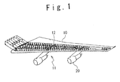
- FIG. 1 shows a wing 10 of an aircraft according to a first embodiment of the present invention.
- the wing 10 is provided with a fuel tank 11 and ribs 12 which are arranged in the fuel tank 11.
- the rib 12 is a structural member of the wing 10.
- the fuel tank 11 stores fuel to be supplied to engines 20.
- FIG. 2 shows a firing prevention structure 30 to prevent an ignition source from being generated in the fuel tank 11.
- the firing prevention structure 30 is provided with a supporting structure 40, a double sleeve 50 and a spacer 53.
- the supporting structure 40 is provided with a clamp 44, a shim 45 and a bracket 41 to support the clamp 44.
- the bracket 41 is provided with a first bracket section 42 and a second bracket section 43.
- the double sleeve 50 is provided with an inner sleeve 51 and an outer sleeve 52.
- a pipe 14 passes through a hole 13 formed in the rib 12.
- the pipe 14 is a fuel line and a hydraulic line. Because the rib 12 and the pipe 14 are made of metals, it is required to prevent s spark discharge between the rib 12 and the pipe 14.
- the supporting structure 40 supports the pipe 14 so as to secure a sufficient distance between the pipe 14 and the rib 12.
- the first bracket section 42 is formed of metal and is attached to the rib 12 with bolts and nuts.
- the second bracket section 43 is formed of metal and is attached to the first bracket section 42 with bolts and nuts.
- the clamp 44 is formed of electric insulating material such as plastic and is attached to the second bracket section 43 with bolts and nuts.
- the clamp 44 holds the pipe 14.
- the shim 45 is formed of electric insulating material such as plastic and is arranged between the clamp 44 and the second bracket section 43. The position of clamp 44 is adjusted by the shim 45 such that the pipe 14 passes through the center of the hole 13.
- the bracket 41 which is provided with the first bracket section 42 and the second bracket section 43 supports the clamp 44 such that the clamp 44 is arranged in a position apart from the hole 13 in a direction of extension of the pipe 14.
- the clamp 44 is an insulating section which electrically insulates the pipe 14 from the rib 12.
- the second bracket section 43 may be formed of electric insulating material such as plastic.
- the insulating section of the supporting structure 40 contains the clamp 44 and the second bracket section 43.
- the double sleeve 50 is inserted into the hole 13 and the pipe 14 passes through the double sleeve 50.
- the double sleeve 50 is attached to the rib 12.
- the inner sleeve 51 and the outer sleeve 52 are each formed of electric insulating material such as plastic.
- the inner sleeve 51 is provided with a tubular shape section 51a and a flange section 51b formed to the tubular section 51a.
- the outer sleeve 52 is provided with a tubular section 52a and a flange section 52b formed to the tubular section 52a.
- the tubular section 52a is inserted into the hole 13, the tubular section 51a is arranged inside the tubular section 52a and the pipe 14 passes through the tubular section 51a.
- the flange section 52b is arranged between the rib 12 and the flange section 51b.
- the spacer 53 is formed of metal and is attached to the rib 12 by bolts and nuts.
- the flange section 51b and the flange section 52b are attached to the spacer 53 and the first bracket section 42 by bolts and nuts.
- the supporting structure 40 Even when the supporting structure 40 is broken down, the sufficient distance is secured between the pipe 14 and the rib 12 by the double sleeve 50. Moreover, even when the pipe 14 touches the double sleeve 50 due to a trouble of the supporting structure 40, it can be surely prevented that a spark discharge happens between the pipe 14 and the rib 12 along the surface of the inner sleeve 51 or the outer sleeve 52, because the inner sleeve 51 is provided with the tubular section 51a and the flange section 51b, and the outer sleeve 52 is provided with the tubular section 52a and the flange section 52b.
- the spark discharge between the rib 12 and the pipe 14 can be prevented by the remaining one.
- first electric insulating material which forms the inner sleeve 51 In order to prevent that the inner sleeve 51, the outer sleeve 52 and the supporting structure 40 are all broken down at a same time, it is desirable that first electric insulating material which forms the inner sleeve 51, second electric insulating material which forms the outer sleeve 52, and third electric insulating material which forms the insulating section of the supporting structure 40 are different from each other.
- the inner sleeve 51, the outer sleeve 52 and the supporting structure 40 provide a redundancy to the firing prevention structure to prevent the generation of the spark discharge between the rib 12 and the pipe 14.
- the highest strength is required for the insulating section of the supporting structure 40 which always supports the pipe 14. Higher strength is required for the inner sleeve 51 which the pipe 14 touches directly first when the supporting structure 40 is broken down. Therefore, when the first to third electric insulating materials are plastic, it is desirable that the tensile strength of the third electric insulating material is the highest among the first to third electric insulating materials, and the tensile strength of the first electric insulating material is next high.
- LYTEX registered trademark
- nylon may be used as the first electric insulating material
- DELRIN registered trademark
- the materials of the inner sleeve 51, the outer sleeve 52, and the insulating section of the supporting structure 40 have a large electrical resistivity, resistance of occurrence of static electricity, and a high tolerance to fuel, the materials are not limited to the above-mentioned examples.
Landscapes
- Engineering & Computer Science (AREA)
- Aviation & Aerospace Engineering (AREA)
- Cooling, Air Intake And Gas Exhaust, And Fuel Tank Arrangements In Propulsion Units (AREA)
- Rigid Pipes And Flexible Pipes (AREA)
Abstract
Description
- The present invention is related to a firing prevention of a fuel tank.
- As disclosed in Federal Aviation Regulation Part 25 Sec. 25.981,
[Online] Federal Aviation Administration.
[retrieved on 2008-10-27] Retrieved From the Internet:
<URL:http://rgl.faa.gov/Regulatory_and_
Guidance_Library/rgFAR.nsf/0/339daee3e0a6379d862574cf0 0641951!OpenDocument>,
the US Federal Aviation Administration promulgated regulation about the firing prevention of a fuel tank. According to this regulation, it is necessary to take measures so as for any ignition source not to generate in the fuel tank even in either of a case of a single failure, a case of a combination of the single trouble and a latent failed state that the relation to the single failure is not low, and a case of a combination of failures having possibilities which are not very low. - [Non-Patent Literature 1]: Federal Aviation
Regulation Part 25 Sec. 25.981
[Online] Federal Aviation Administration.
[retrieved on 2008-10-27] Retrieved From the Internet:<URL:http://rgl.faa.gov/Regulatory_and_Guidan ce_Library/rgFAR.nsf/0/339daee3e0a6379d862574cf0064195 1!OpenDocument> - The subject matter of the present invention is to provide a firing prevention structure of a fuel tank in which it is prevented that an ignition source is generated in the fuel tank, and an aircraft using the same.
- The firing prevention structure of a fuel tank in a first aspect of the present invention, is provided with a double sleeve configured to pass through a hole formed in a rib; and a supporting structure configured to support a pipe which passes through said double sleeve. The supporting structure is attached to said rib, and said supporting structure comprises an insulating section which electrically insulates said pipe and said rib from each other. The double sleeve is formed of electrically insulating material.
- Therefore, even when two of three of the inner sleeve of the double sleeve, the outer sleeve of the double sleeve, and the supporting structure are broken down, any spark discharge between the rib and the pipe is prevented by the remaining one.
- Preferably, said double sleeve comprises an inner sleeve and an outer sleeve, said inner sleeve is formed of a first electrically insulating material, and said outer sleeve is formed of a second electrically insulating material which is different from said first electrically insulating material. The insulating section is formed of a third electrically insulating material which is different from said first electrically insulating material and said second electrically insulating material.
- Therefore, it can be prevented that three of the inner sleeve, the outer sleeve and the supporting structure are broken down at a same time.
- Preferably, said first electrically insulating material, said second electrically insulating material and said third electrically insulating material are plastic materials, respectively. The first electrically insulating material is higher in tensile strength than said second electrically insulating material, and said third electrically insulating material is higher in tensile strength than said first electrically insulating material.
- Therefore, the strength of the insulating section of the supporting structure to support the pipe is the highest and the strength of the inner sleeve to support the pipe when the supporting structure is broken down becomes next high.
- Preferably, the double sleeve is provided with a flange.
- Therefore, any spark discharge between the pipe and the rib along the surface of the double sleeve happens can be surely prevented.
- The aircraft in a second aspect of the present invention is provided with the above-mentioned firing prevention structure of the fuel tank.
- According to the present invention, the firing prevention structure of the fuel tank and the aircraft are provided, in which it is prevented that an ignition source is generated in the fuel tank.
- The above object, other objects, effects and features of the present invention will be made clear from the description of the embodiments in conjunction with the following drawings:
-
FIG. 1 shows a wing of an aircraft according to a first embodiment of the present invention; -
FIG. 2 is a perspective view of a firing prevention structure according to the first embodiment; and -
FIG. 3 is a sectional view of the firing prevention structure. - Hereinafter, a firing prevention structure of a fuel tank according to the present invention will be described in detail with reference to the attached drawings.
-
FIG. 1 shows awing 10 of an aircraft according to a first embodiment of the present invention. Thewing 10 is provided with afuel tank 11 andribs 12 which are arranged in thefuel tank 11. Therib 12 is a structural member of thewing 10. Thefuel tank 11 stores fuel to be supplied toengines 20. -
FIG. 2 shows afiring prevention structure 30 to prevent an ignition source from being generated in thefuel tank 11. Thefiring prevention structure 30 is provided with a supportingstructure 40, adouble sleeve 50 and aspacer 53. The supportingstructure 40 is provided with aclamp 44, ashim 45 and abracket 41 to support theclamp 44. Thebracket 41 is provided with afirst bracket section 42 and asecond bracket section 43. Thedouble sleeve 50 is provided with aninner sleeve 51 and anouter sleeve 52. - Hereinafter, the
firing prevention structure 30 will be described in detail. - Referring to
FIG. 3 , apipe 14 passes through ahole 13 formed in therib 12. For example, thepipe 14 is a fuel line and a hydraulic line. Because therib 12 and thepipe 14 are made of metals, it is required to prevent s spark discharge between therib 12 and thepipe 14. - The supporting
structure 40 supports thepipe 14 so as to secure a sufficient distance between thepipe 14 and therib 12. Thefirst bracket section 42 is formed of metal and is attached to therib 12 with bolts and nuts. Thesecond bracket section 43 is formed of metal and is attached to thefirst bracket section 42 with bolts and nuts. Theclamp 44 is formed of electric insulating material such as plastic and is attached to thesecond bracket section 43 with bolts and nuts. Theclamp 44 holds thepipe 14. Theshim 45 is formed of electric insulating material such as plastic and is arranged between theclamp 44 and thesecond bracket section 43. The position ofclamp 44 is adjusted by theshim 45 such that thepipe 14 passes through the center of thehole 13. Thebracket 41 which is provided with thefirst bracket section 42 and thesecond bracket section 43 supports theclamp 44 such that theclamp 44 is arranged in a position apart from thehole 13 in a direction of extension of thepipe 14. Theclamp 44 is an insulating section which electrically insulates thepipe 14 from therib 12. It should be noted that thesecond bracket section 43 may be formed of electric insulating material such as plastic. In this case, the insulating section of the supportingstructure 40 contains theclamp 44 and thesecond bracket section 43. - Because the sufficient distance is secured between the
pipe 14 and therib 12 by the supportingstructure 40, a spark discharge between therib 12 and thepipe 14 can be prevented. - The
double sleeve 50 is inserted into thehole 13 and thepipe 14 passes through thedouble sleeve 50. Thedouble sleeve 50 is attached to therib 12. Theinner sleeve 51 and theouter sleeve 52 are each formed of electric insulating material such as plastic. Theinner sleeve 51 is provided with atubular shape section 51a and aflange section 51b formed to thetubular section 51a. Theouter sleeve 52 is provided with atubular section 52a and aflange section 52b formed to thetubular section 52a. Thetubular section 52a is inserted into thehole 13, thetubular section 51a is arranged inside thetubular section 52a and thepipe 14 passes through thetubular section 51a. Theflange section 52b is arranged between therib 12 and theflange section 51b. Thespacer 53 is formed of metal and is attached to therib 12 by bolts and nuts. Theflange section 51b and theflange section 52b are attached to thespacer 53 and thefirst bracket section 42 by bolts and nuts. - Even when the supporting
structure 40 is broken down, the sufficient distance is secured between thepipe 14 and therib 12 by thedouble sleeve 50. Moreover, even when thepipe 14 touches thedouble sleeve 50 due to a trouble of the supportingstructure 40, it can be surely prevented that a spark discharge happens between thepipe 14 and therib 12 along the surface of theinner sleeve 51 or theouter sleeve 52, because theinner sleeve 51 is provided with thetubular section 51a and theflange section 51b, and theouter sleeve 52 is provided with thetubular section 52a and theflange section 52b. - According to the present embodiment, even when two among three of the supporting
structure 40, theinner sleeve 51, and theouter sleeve 52 are broken down, the spark discharge between therib 12 and thepipe 14 can be prevented by the remaining one. - In order to prevent that the
inner sleeve 51, theouter sleeve 52 and the supportingstructure 40 are all broken down at a same time, it is desirable that first electric insulating material which forms theinner sleeve 51, second electric insulating material which forms theouter sleeve 52, and third electric insulating material which forms the insulating section of the supportingstructure 40 are different from each other. Thus, theinner sleeve 51, theouter sleeve 52 and the supportingstructure 40 provide a redundancy to the firing prevention structure to prevent the generation of the spark discharge between therib 12 and thepipe 14. - The highest strength is required for the insulating section of the supporting
structure 40 which always supports thepipe 14. Higher strength is required for theinner sleeve 51 which thepipe 14 touches directly first when the supportingstructure 40 is broken down. Therefore, when the first to third electric insulating materials are plastic, it is desirable that the tensile strength of the third electric insulating material is the highest among the first to third electric insulating materials, and the tensile strength of the first electric insulating material is next high. For example, LYTEX (registered trademark) may be used as the third electric insulating material, nylon may be used as the first electric insulating material, DELRIN (registered trademark) may be used as the second electric insulating material. - If the materials of the
inner sleeve 51, theouter sleeve 52, and the insulating section of the supportingstructure 40 have a large electrical resistivity, resistance of occurrence of static electricity, and a high tolerance to fuel, the materials are not limited to the above-mentioned examples. - As described above, the present invention has been described with reference to the embodiments. However, the present invention is not limited to the above embodiments. Various modifications can be carried out to the above embodiments.
- This patent application claims a priority on convention based on Japanese Patent Application No.
2009-046178 filed on February 27, 2009
Claims (5)
- A firing prevention structure of a fuel tank, comprising:a double sleeve configured to pass through a hole formed in a rib; anda supporting structure configured to support a pipe which passes through said double sleeve,wherein said supporting structure is attached to said rib, andwherein said supporting structure comprises an insulating section which electrically insulates said pipe and said rib from each other, and said double sleeve is formed of electrically insulating material.
- The firing prevention structure according to claim 1, wherein said double sleeve comprises an inner sleeve and an outer sleeve,
wherein said inner sleeve is formed of a first electrically insulating material,
wherein said outer sleeve is formed of a second electrically insulating material which is different from said first electrically insulating material, and
wherein said insulating section is formed of a third electrically insulating material which is different from said first electrically insulating material and said second electrically insulating material. - The firing prevention structure according to claim 2, wherein said first electrically insulating material, said second electrically insulating material and said third electrically insulating material are plastic materials, respectively, and
wherein said first electrically insulating material is higher in tensile strength than said second electrically insulating material, and said third electrically insulating material is higher in tensile strength than said first electrically insulating material. - The firing prevention structure according to any of claims 1 to 3, wherein said double sleeve comprises a flange.
- An aircraft comprising the firing prevention structure of the fuel tank according to any of claims 1 to 4.
Applications Claiming Priority (2)
| Application Number | Priority Date | Filing Date | Title |
|---|---|---|---|
| JP2009046178A JP5210925B2 (en) | 2009-02-27 | 2009-02-27 | Fuel tank ignition prevention structure |
| PCT/JP2010/052384 WO2010098243A1 (en) | 2009-02-27 | 2010-02-17 | Fuel-tank ignition prevention structure |
Publications (3)
| Publication Number | Publication Date |
|---|---|
| EP2402252A1 true EP2402252A1 (en) | 2012-01-04 |
| EP2402252A4 EP2402252A4 (en) | 2017-07-05 |
| EP2402252B1 EP2402252B1 (en) | 2019-04-10 |
Family
ID=42665452
Family Applications (1)
| Application Number | Title | Priority Date | Filing Date |
|---|---|---|---|
| EP10746124.6A Active EP2402252B1 (en) | 2009-02-27 | 2010-02-17 | Fuel-tank ignition prevention structure |
Country Status (8)
| Country | Link |
|---|---|
| US (1) | US8894014B2 (en) |
| EP (1) | EP2402252B1 (en) |
| JP (1) | JP5210925B2 (en) |
| CN (1) | CN102333698B (en) |
| BR (1) | BRPI1009554B1 (en) |
| CA (1) | CA2753692C (en) |
| RU (1) | RU2487060C2 (en) |
| WO (1) | WO2010098243A1 (en) |
Cited By (1)
| Publication number | Priority date | Publication date | Assignee | Title |
|---|---|---|---|---|
| EP3611097A1 (en) * | 2018-08-15 | 2020-02-19 | Short Brothers Plc | Electrical isolator fitting |
Families Citing this family (9)
| Publication number | Priority date | Publication date | Assignee | Title |
|---|---|---|---|---|
| JP5737903B2 (en) | 2010-10-26 | 2015-06-17 | 三菱重工業株式会社 | Piping support structure for aircraft |
| FR2983276B1 (en) * | 2011-11-30 | 2014-08-22 | Airbus Operations Sas | DEVICE FOR FIXING A FLUID TRANSPORT CIRCUIT TO AN ELEMENT OF THE STRUCTURE OF AN AIRCRAFT AND ASSOCIATED AIRCRAFT |
| JP6674740B2 (en) * | 2015-02-10 | 2020-04-01 | 三菱航空機株式会社 | Burst disk device and aircraft |
| US9920859B2 (en) * | 2015-06-08 | 2018-03-20 | The Boeing Company | Electromagnetic effects-sensitive pass-through mounting assemblies with adjustable offset |
| GB2542121A (en) | 2015-09-08 | 2017-03-15 | Airbus Operations Ltd | Pipe installation |
| JP6661369B2 (en) * | 2015-12-25 | 2020-03-11 | 三菱航空機株式会社 | Seat between high-temperature duct and structural member of aircraft, aircraft duct structure, and aircraft |
| US11168839B2 (en) * | 2017-06-20 | 2021-11-09 | The Boeing Company | Transport element support assembly |
| KR102395191B1 (en) * | 2017-10-12 | 2022-05-06 | 삼성전자주식회사 | Sensor module, apparatus for manufacturing semiconductor, and method of manufacturing semiconductor device |
| US11332258B2 (en) * | 2018-09-27 | 2022-05-17 | Textron Innovations Inc. | Method for enhanced fuel cell protection from adjacent damaged components |
Family Cites Families (18)
| Publication number | Priority date | Publication date | Assignee | Title |
|---|---|---|---|---|
| US1859311A (en) * | 1926-06-01 | 1932-05-24 | Jr Joseph H Mcevoy | Pipe joint |
| SU459942A1 (en) * | 1973-05-28 | 2005-05-10 | И.В. Емельянов | DEVICE FOR PREVENTION OF EXPLOSION OF EXPLOSIVE TANKS OF AIRCRAFT |
| US4630789A (en) * | 1983-09-23 | 1986-12-23 | The Boeing Company | Dielectric isolated fuel and hydraulic tubes |
| US4654747A (en) * | 1985-09-30 | 1987-03-31 | The Boeing Company | Dielectric isolation of metallic conduits |
| FR2617568B1 (en) * | 1987-07-02 | 1989-10-20 | Aerospatiale | TUBE FOR THE CIRCULATION OF A FLAMMABLE FLUID, AND PIPING MADE FROM SUCH TUBES |
| US4971268A (en) * | 1988-11-23 | 1990-11-20 | The Boeing Company | Dielectric support and wear sleeve |
| AT394768B (en) * | 1990-11-02 | 1992-06-25 | Chamottewaren U Thonoefenfabri | BURNER FLAME GUIDE PART |
| JP2586674Y2 (en) * | 1991-09-30 | 1998-12-09 | 株式会社白山製作所 | Cable movement prevention device |
| JPH05300708A (en) * | 1992-04-17 | 1993-11-12 | Toshiba Corp | Manufacture of heat-resistant insulting coil |
| DE59304840D1 (en) * | 1992-10-05 | 1997-01-30 | Hoechst Ag | POLYESTER SHAPED BODIES CONTAINING COVALENTLY INCLUDED OXIDE PARTICLES |
| US6919012B1 (en) * | 2003-03-25 | 2005-07-19 | Olimex Group, Inc. | Method of making a composite article comprising a ceramic coating |
| JP4533006B2 (en) * | 2004-06-08 | 2010-08-25 | 積水化学工業株式会社 | Fire-proof compartment penetration structure and construction method of fire-proof compartment penetration |
| US20060099843A1 (en) * | 2004-11-01 | 2006-05-11 | Fullner Todd C | Dielectric fittings |
| FR2877774B1 (en) * | 2004-11-08 | 2010-11-05 | Airbus France | CONNECTOR ASSEMBLY FOR AIRCRAFT |
| WO2006054572A1 (en) | 2004-11-17 | 2006-05-26 | Sekisui Chemical Co., Ltd. | Structure of pierced part of section unit |
| JP2007312599A (en) * | 2004-11-17 | 2007-11-29 | Sekisui Chem Co Ltd | Penetration through structure of compartment |
| EP1939088A4 (en) * | 2005-09-29 | 2012-04-18 | Airbus Operations Sl | Method of protecting fuel tanks that are made from composite materials against electric discharges |
| JP2009046178A (en) | 2007-08-21 | 2009-03-05 | Ricoh Co Ltd | Packing equipment |
-
2009
- 2009-02-27 JP JP2009046178A patent/JP5210925B2/en active Active
-
2010
- 2010-02-17 CN CN201080009589.1A patent/CN102333698B/en not_active Expired - Fee Related
- 2010-02-17 WO PCT/JP2010/052384 patent/WO2010098243A1/en not_active Ceased
- 2010-02-17 BR BRPI1009554-3A patent/BRPI1009554B1/en not_active IP Right Cessation
- 2010-02-17 EP EP10746124.6A patent/EP2402252B1/en active Active
- 2010-02-17 RU RU2011139330/11A patent/RU2487060C2/en active
- 2010-02-17 US US13/203,323 patent/US8894014B2/en active Active
- 2010-02-17 CA CA2753692A patent/CA2753692C/en not_active Expired - Fee Related
Non-Patent Citations (1)
| Title |
|---|
| See references of WO2010098243A1 * |
Cited By (2)
| Publication number | Priority date | Publication date | Assignee | Title |
|---|---|---|---|---|
| EP3611097A1 (en) * | 2018-08-15 | 2020-02-19 | Short Brothers Plc | Electrical isolator fitting |
| US11352147B2 (en) | 2018-08-15 | 2022-06-07 | Short Brothers Plc | Electrical isolator fitting |
Also Published As
| Publication number | Publication date |
|---|---|
| BRPI1009554B1 (en) | 2020-06-23 |
| US20120012709A1 (en) | 2012-01-19 |
| WO2010098243A1 (en) | 2010-09-02 |
| RU2011139330A (en) | 2013-04-10 |
| EP2402252A4 (en) | 2017-07-05 |
| RU2487060C2 (en) | 2013-07-10 |
| US8894014B2 (en) | 2014-11-25 |
| CA2753692C (en) | 2014-08-12 |
| CN102333698B (en) | 2015-12-16 |
| CA2753692A1 (en) | 2010-09-02 |
| BRPI1009554A2 (en) | 2019-04-09 |
| EP2402252B1 (en) | 2019-04-10 |
| CN102333698A (en) | 2012-01-25 |
| JP2010201943A (en) | 2010-09-16 |
| JP5210925B2 (en) | 2013-06-12 |
Similar Documents
| Publication | Publication Date | Title |
|---|---|---|
| EP2402252B1 (en) | Fuel-tank ignition prevention structure | |
| US9400066B2 (en) | Fixture device for an aircraft tubing | |
| CN103889838A (en) | Penetrating structure for ESD protection | |
| JP5155833B2 (en) | Aircraft fuel tank | |
| RU2604470C9 (en) | Improved conductivity on hydraulic system fittings owing to use of intermediate layer of soft metal | |
| EP3509172B1 (en) | An aerial vehicle and a signal line protection assembly thereof | |
| EP2712808B1 (en) | Suspension system for aircraft auxiliary power unit with elastomeric member | |
| EP3492388B1 (en) | Waste-gas line for a battery in an aircraft | |
| JP2012532797A (en) | Equipment for protecting piping from lightning strikes | |
| TW201221799A (en) | Vibration damping and isolation mounting device | |
| EP2733365B1 (en) | Bushing assemblies and associated method | |
| JP6283200B2 (en) | Electrical cable mounting bracket assembly | |
| JP6060165B2 (en) | Bushing for use in providing electromagnetic effect protection | |
| CN101346281B (en) | Current insulation apparatus used for fuel system | |
| EP1939088A1 (en) | Method of protecting fuel tanks that are made from composite materials against electric discharges | |
| EP3132174B1 (en) | Feedback bulkhead connector assembly | |
| EP3181883B1 (en) | Cylindrical case and jet engine | |
| US20110048798A1 (en) | Collar for maintaining electric cables | |
| US20150021455A1 (en) | Turbine engine support part of hybrid structure | |
| AU2020271141A1 (en) | Aircraft engine adapter system | |
| JP4818144B2 (en) | High liquid level alarm device | |
| DE602006004162D1 (en) | Lightning protected telescopic refueling mast for aircraft | |
| US20160087372A1 (en) | Strain relief structure | |
| CN108933385A (en) | Distribution system and the method for managing wherein breaker |
Legal Events
| Date | Code | Title | Description |
|---|---|---|---|
| PUAI | Public reference made under article 153(3) epc to a published international application that has entered the european phase |
Free format text: ORIGINAL CODE: 0009012 |
|
| 17P | Request for examination filed |
Effective date: 20110826 |
|
| AK | Designated contracting states |
Kind code of ref document: A1 Designated state(s): AT BE BG CH CY CZ DE DK EE ES FI FR GB GR HR HU IE IS IT LI LT LU LV MC MK MT NL NO PL PT RO SE SI SK SM TR |
|
| DAX | Request for extension of the european patent (deleted) | ||
| RA4 | Supplementary search report drawn up and despatched (corrected) |
Effective date: 20170607 |
|
| RIC1 | Information provided on ipc code assigned before grant |
Ipc: B64D 37/32 20060101AFI20170531BHEP Ipc: B64D 45/02 20060101ALI20170531BHEP |
|
| RIC1 | Information provided on ipc code assigned before grant |
Ipc: B64D 45/02 20060101ALI20180712BHEP Ipc: B64D 37/32 20060101AFI20180712BHEP |
|
| GRAP | Despatch of communication of intention to grant a patent |
Free format text: ORIGINAL CODE: EPIDOSNIGR1 |
|
| STAA | Information on the status of an ep patent application or granted ep patent |
Free format text: STATUS: GRANT OF PATENT IS INTENDED |
|
| INTG | Intention to grant announced |
Effective date: 20180914 |
|
| INTG | Intention to grant announced |
Effective date: 20180914 |
|
| GRAS | Grant fee paid |
Free format text: ORIGINAL CODE: EPIDOSNIGR3 |
|
| GRAA | (expected) grant |
Free format text: ORIGINAL CODE: 0009210 |
|
| STAA | Information on the status of an ep patent application or granted ep patent |
Free format text: STATUS: THE PATENT HAS BEEN GRANTED |
|
| AK | Designated contracting states |
Kind code of ref document: B1 Designated state(s): AT BE BG CH CY CZ DE DK EE ES FI FR GB GR HR HU IE IS IT LI LT LU LV MC MK MT NL NO PL PT RO SE SI SK SM TR |
|
| REG | Reference to a national code |
Ref country code: GB Ref legal event code: FG4D |
|
| REG | Reference to a national code |
Ref country code: CH Ref legal event code: EP Ref country code: AT Ref legal event code: REF Ref document number: 1118324 Country of ref document: AT Kind code of ref document: T Effective date: 20190415 |
|
| REG | Reference to a national code |
Ref country code: IE Ref legal event code: FG4D |
|
| REG | Reference to a national code |
Ref country code: DE Ref legal event code: R096 Ref document number: 602010058158 Country of ref document: DE |
|
| REG | Reference to a national code |
Ref country code: NL Ref legal event code: MP Effective date: 20190410 |
|
| REG | Reference to a national code |
Ref country code: LT Ref legal event code: MG4D |
|
| REG | Reference to a national code |
Ref country code: AT Ref legal event code: MK05 Ref document number: 1118324 Country of ref document: AT Kind code of ref document: T Effective date: 20190410 |
|
| PG25 | Lapsed in a contracting state [announced via postgrant information from national office to epo] |
Ref country code: NL Free format text: LAPSE BECAUSE OF FAILURE TO SUBMIT A TRANSLATION OF THE DESCRIPTION OR TO PAY THE FEE WITHIN THE PRESCRIBED TIME-LIMIT Effective date: 20190410 |
|
| PG25 | Lapsed in a contracting state [announced via postgrant information from national office to epo] |
Ref country code: NO Free format text: LAPSE BECAUSE OF FAILURE TO SUBMIT A TRANSLATION OF THE DESCRIPTION OR TO PAY THE FEE WITHIN THE PRESCRIBED TIME-LIMIT Effective date: 20190710 Ref country code: PT Free format text: LAPSE BECAUSE OF FAILURE TO SUBMIT A TRANSLATION OF THE DESCRIPTION OR TO PAY THE FEE WITHIN THE PRESCRIBED TIME-LIMIT Effective date: 20190910 Ref country code: SE Free format text: LAPSE BECAUSE OF FAILURE TO SUBMIT A TRANSLATION OF THE DESCRIPTION OR TO PAY THE FEE WITHIN THE PRESCRIBED TIME-LIMIT Effective date: 20190410 Ref country code: FI Free format text: LAPSE BECAUSE OF FAILURE TO SUBMIT A TRANSLATION OF THE DESCRIPTION OR TO PAY THE FEE WITHIN THE PRESCRIBED TIME-LIMIT Effective date: 20190410 Ref country code: ES Free format text: LAPSE BECAUSE OF FAILURE TO SUBMIT A TRANSLATION OF THE DESCRIPTION OR TO PAY THE FEE WITHIN THE PRESCRIBED TIME-LIMIT Effective date: 20190410 Ref country code: HR Free format text: LAPSE BECAUSE OF FAILURE TO SUBMIT A TRANSLATION OF THE DESCRIPTION OR TO PAY THE FEE WITHIN THE PRESCRIBED TIME-LIMIT Effective date: 20190410 Ref country code: LT Free format text: LAPSE BECAUSE OF FAILURE TO SUBMIT A TRANSLATION OF THE DESCRIPTION OR TO PAY THE FEE WITHIN THE PRESCRIBED TIME-LIMIT Effective date: 20190410 |
|
| PG25 | Lapsed in a contracting state [announced via postgrant information from national office to epo] |
Ref country code: BG Free format text: LAPSE BECAUSE OF FAILURE TO SUBMIT A TRANSLATION OF THE DESCRIPTION OR TO PAY THE FEE WITHIN THE PRESCRIBED TIME-LIMIT Effective date: 20190710 Ref country code: PL Free format text: LAPSE BECAUSE OF FAILURE TO SUBMIT A TRANSLATION OF THE DESCRIPTION OR TO PAY THE FEE WITHIN THE PRESCRIBED TIME-LIMIT Effective date: 20190410 Ref country code: LV Free format text: LAPSE BECAUSE OF FAILURE TO SUBMIT A TRANSLATION OF THE DESCRIPTION OR TO PAY THE FEE WITHIN THE PRESCRIBED TIME-LIMIT Effective date: 20190410 Ref country code: GR Free format text: LAPSE BECAUSE OF FAILURE TO SUBMIT A TRANSLATION OF THE DESCRIPTION OR TO PAY THE FEE WITHIN THE PRESCRIBED TIME-LIMIT Effective date: 20190711 |
|
| PG25 | Lapsed in a contracting state [announced via postgrant information from national office to epo] |
Ref country code: AT Free format text: LAPSE BECAUSE OF FAILURE TO SUBMIT A TRANSLATION OF THE DESCRIPTION OR TO PAY THE FEE WITHIN THE PRESCRIBED TIME-LIMIT Effective date: 20190410 Ref country code: IS Free format text: LAPSE BECAUSE OF FAILURE TO SUBMIT A TRANSLATION OF THE DESCRIPTION OR TO PAY THE FEE WITHIN THE PRESCRIBED TIME-LIMIT Effective date: 20190810 |
|
| REG | Reference to a national code |
Ref country code: DE Ref legal event code: R097 Ref document number: 602010058158 Country of ref document: DE |
|
| PG25 | Lapsed in a contracting state [announced via postgrant information from national office to epo] |
Ref country code: SK Free format text: LAPSE BECAUSE OF FAILURE TO SUBMIT A TRANSLATION OF THE DESCRIPTION OR TO PAY THE FEE WITHIN THE PRESCRIBED TIME-LIMIT Effective date: 20190410 Ref country code: RO Free format text: LAPSE BECAUSE OF FAILURE TO SUBMIT A TRANSLATION OF THE DESCRIPTION OR TO PAY THE FEE WITHIN THE PRESCRIBED TIME-LIMIT Effective date: 20190410 Ref country code: CZ Free format text: LAPSE BECAUSE OF FAILURE TO SUBMIT A TRANSLATION OF THE DESCRIPTION OR TO PAY THE FEE WITHIN THE PRESCRIBED TIME-LIMIT Effective date: 20190410 Ref country code: EE Free format text: LAPSE BECAUSE OF FAILURE TO SUBMIT A TRANSLATION OF THE DESCRIPTION OR TO PAY THE FEE WITHIN THE PRESCRIBED TIME-LIMIT Effective date: 20190410 Ref country code: DK Free format text: LAPSE BECAUSE OF FAILURE TO SUBMIT A TRANSLATION OF THE DESCRIPTION OR TO PAY THE FEE WITHIN THE PRESCRIBED TIME-LIMIT Effective date: 20190410 |
|
| PLBE | No opposition filed within time limit |
Free format text: ORIGINAL CODE: 0009261 |
|
| STAA | Information on the status of an ep patent application or granted ep patent |
Free format text: STATUS: NO OPPOSITION FILED WITHIN TIME LIMIT |
|
| PG25 | Lapsed in a contracting state [announced via postgrant information from national office to epo] |
Ref country code: IT Free format text: LAPSE BECAUSE OF FAILURE TO SUBMIT A TRANSLATION OF THE DESCRIPTION OR TO PAY THE FEE WITHIN THE PRESCRIBED TIME-LIMIT Effective date: 20190410 Ref country code: SM Free format text: LAPSE BECAUSE OF FAILURE TO SUBMIT A TRANSLATION OF THE DESCRIPTION OR TO PAY THE FEE WITHIN THE PRESCRIBED TIME-LIMIT Effective date: 20190410 |
|
| 26N | No opposition filed |
Effective date: 20200113 |
|
| PG25 | Lapsed in a contracting state [announced via postgrant information from national office to epo] |
Ref country code: TR Free format text: LAPSE BECAUSE OF FAILURE TO SUBMIT A TRANSLATION OF THE DESCRIPTION OR TO PAY THE FEE WITHIN THE PRESCRIBED TIME-LIMIT Effective date: 20190410 |
|
| PG25 | Lapsed in a contracting state [announced via postgrant information from national office to epo] |
Ref country code: SI Free format text: LAPSE BECAUSE OF FAILURE TO SUBMIT A TRANSLATION OF THE DESCRIPTION OR TO PAY THE FEE WITHIN THE PRESCRIBED TIME-LIMIT Effective date: 20190410 |
|
| REG | Reference to a national code |
Ref country code: CH Ref legal event code: PL |
|
| GBPC | Gb: european patent ceased through non-payment of renewal fee |
Effective date: 20200217 |
|
| REG | Reference to a national code |
Ref country code: BE Ref legal event code: MM Effective date: 20200229 |
|
| PG25 | Lapsed in a contracting state [announced via postgrant information from national office to epo] |
Ref country code: MC Free format text: LAPSE BECAUSE OF FAILURE TO SUBMIT A TRANSLATION OF THE DESCRIPTION OR TO PAY THE FEE WITHIN THE PRESCRIBED TIME-LIMIT Effective date: 20190410 Ref country code: LU Free format text: LAPSE BECAUSE OF NON-PAYMENT OF DUE FEES Effective date: 20200217 |
|
| PG25 | Lapsed in a contracting state [announced via postgrant information from national office to epo] |
Ref country code: LI Free format text: LAPSE BECAUSE OF NON-PAYMENT OF DUE FEES Effective date: 20200229 Ref country code: CH Free format text: LAPSE BECAUSE OF NON-PAYMENT OF DUE FEES Effective date: 20200229 |
|
| PG25 | Lapsed in a contracting state [announced via postgrant information from national office to epo] |
Ref country code: GB Free format text: LAPSE BECAUSE OF NON-PAYMENT OF DUE FEES Effective date: 20200217 Ref country code: IE Free format text: LAPSE BECAUSE OF NON-PAYMENT OF DUE FEES Effective date: 20200217 |
|
| PG25 | Lapsed in a contracting state [announced via postgrant information from national office to epo] |
Ref country code: BE Free format text: LAPSE BECAUSE OF NON-PAYMENT OF DUE FEES Effective date: 20200229 |
|
| PG25 | Lapsed in a contracting state [announced via postgrant information from national office to epo] |
Ref country code: MT Free format text: LAPSE BECAUSE OF FAILURE TO SUBMIT A TRANSLATION OF THE DESCRIPTION OR TO PAY THE FEE WITHIN THE PRESCRIBED TIME-LIMIT Effective date: 20190410 Ref country code: CY Free format text: LAPSE BECAUSE OF FAILURE TO SUBMIT A TRANSLATION OF THE DESCRIPTION OR TO PAY THE FEE WITHIN THE PRESCRIBED TIME-LIMIT Effective date: 20190410 |
|
| PG25 | Lapsed in a contracting state [announced via postgrant information from national office to epo] |
Ref country code: MK Free format text: LAPSE BECAUSE OF FAILURE TO SUBMIT A TRANSLATION OF THE DESCRIPTION OR TO PAY THE FEE WITHIN THE PRESCRIBED TIME-LIMIT Effective date: 20190410 |
|
| PGFP | Annual fee paid to national office [announced via postgrant information from national office to epo] |
Ref country code: FR Payment date: 20251231 Year of fee payment: 17 |
|
| PGFP | Annual fee paid to national office [announced via postgrant information from national office to epo] |
Ref country code: DE Payment date: 20251230 Year of fee payment: 17 |