EP2402204A1 - Electrically driven vehicle - Google Patents
Electrically driven vehicle Download PDFInfo
- Publication number
- EP2402204A1 EP2402204A1 EP09848581A EP09848581A EP2402204A1 EP 2402204 A1 EP2402204 A1 EP 2402204A1 EP 09848581 A EP09848581 A EP 09848581A EP 09848581 A EP09848581 A EP 09848581A EP 2402204 A1 EP2402204 A1 EP 2402204A1
- Authority
- EP
- European Patent Office
- Prior art keywords
- battery
- power
- generating unit
- power supply
- vehicle
- Prior art date
- Legal status (The legal status is an assumption and is not a legal conclusion. Google has not performed a legal analysis and makes no representation as to the accuracy of the status listed.)
- Granted
Links
Images

Classifications
-
- B—PERFORMING OPERATIONS; TRANSPORTING
- B60—VEHICLES IN GENERAL
- B60L—PROPULSION OF ELECTRICALLY-PROPELLED VEHICLES; SUPPLYING ELECTRIC POWER FOR AUXILIARY EQUIPMENT OF ELECTRICALLY-PROPELLED VEHICLES; ELECTRODYNAMIC BRAKE SYSTEMS FOR VEHICLES IN GENERAL; MAGNETIC SUSPENSION OR LEVITATION FOR VEHICLES; MONITORING OPERATING VARIABLES OF ELECTRICALLY-PROPELLED VEHICLES; ELECTRIC SAFETY DEVICES FOR ELECTRICALLY-PROPELLED VEHICLES
- B60L53/00—Methods of charging batteries, specially adapted for electric vehicles; Charging stations or on-board charging equipment therefor; Exchange of energy storage elements in electric vehicles
- B60L53/10—Methods of charging batteries, specially adapted for electric vehicles; Charging stations or on-board charging equipment therefor; Exchange of energy storage elements in electric vehicles characterised by the energy transfer between the charging station and the vehicle
- B60L53/14—Conductive energy transfer
-
- B—PERFORMING OPERATIONS; TRANSPORTING
- B60—VEHICLES IN GENERAL
- B60K—ARRANGEMENT OR MOUNTING OF PROPULSION UNITS OR OF TRANSMISSIONS IN VEHICLES; ARRANGEMENT OR MOUNTING OF PLURAL DIVERSE PRIME-MOVERS IN VEHICLES; AUXILIARY DRIVES FOR VEHICLES; INSTRUMENTATION OR DASHBOARDS FOR VEHICLES; ARRANGEMENTS IN CONNECTION WITH COOLING, AIR INTAKE, GAS EXHAUST OR FUEL SUPPLY OF PROPULSION UNITS IN VEHICLES
- B60K6/00—Arrangement or mounting of plural diverse prime-movers for mutual or common propulsion, e.g. hybrid propulsion systems comprising electric motors and internal combustion engines ; Control systems therefor, i.e. systems controlling two or more prime movers, or controlling one of these prime movers and any of the transmission, drive or drive units Informative references: mechanical gearings with secondary electric drive F16H3/72; arrangements for handling mechanical energy structurally associated with the dynamo-electric machine H02K7/00; machines comprising structurally interrelated motor and generator parts H02K51/00; dynamo-electric machines not otherwise provided for in H02K see H02K99/00
- B60K6/20—Arrangement or mounting of plural diverse prime-movers for mutual or common propulsion, e.g. hybrid propulsion systems comprising electric motors and internal combustion engines ; Control systems therefor, i.e. systems controlling two or more prime movers, or controlling one of these prime movers and any of the transmission, drive or drive units Informative references: mechanical gearings with secondary electric drive F16H3/72; arrangements for handling mechanical energy structurally associated with the dynamo-electric machine H02K7/00; machines comprising structurally interrelated motor and generator parts H02K51/00; dynamo-electric machines not otherwise provided for in H02K see H02K99/00 the prime-movers consisting of electric motors and internal combustion engines, e.g. HEVs
- B60K6/42—Arrangement or mounting of plural diverse prime-movers for mutual or common propulsion, e.g. hybrid propulsion systems comprising electric motors and internal combustion engines ; Control systems therefor, i.e. systems controlling two or more prime movers, or controlling one of these prime movers and any of the transmission, drive or drive units Informative references: mechanical gearings with secondary electric drive F16H3/72; arrangements for handling mechanical energy structurally associated with the dynamo-electric machine H02K7/00; machines comprising structurally interrelated motor and generator parts H02K51/00; dynamo-electric machines not otherwise provided for in H02K see H02K99/00 the prime-movers consisting of electric motors and internal combustion engines, e.g. HEVs characterised by the architecture of the hybrid electric vehicle
- B60K6/46—Series type
-
- B—PERFORMING OPERATIONS; TRANSPORTING
- B60—VEHICLES IN GENERAL
- B60L—PROPULSION OF ELECTRICALLY-PROPELLED VEHICLES; SUPPLYING ELECTRIC POWER FOR AUXILIARY EQUIPMENT OF ELECTRICALLY-PROPELLED VEHICLES; ELECTRODYNAMIC BRAKE SYSTEMS FOR VEHICLES IN GENERAL; MAGNETIC SUSPENSION OR LEVITATION FOR VEHICLES; MONITORING OPERATING VARIABLES OF ELECTRICALLY-PROPELLED VEHICLES; ELECTRIC SAFETY DEVICES FOR ELECTRICALLY-PROPELLED VEHICLES
- B60L50/00—Electric propulsion with power supplied within the vehicle
- B60L50/10—Electric propulsion with power supplied within the vehicle using propulsion power supplied by engine-driven generators, e.g. generators driven by combustion engines
-
- B—PERFORMING OPERATIONS; TRANSPORTING
- B60—VEHICLES IN GENERAL
- B60L—PROPULSION OF ELECTRICALLY-PROPELLED VEHICLES; SUPPLYING ELECTRIC POWER FOR AUXILIARY EQUIPMENT OF ELECTRICALLY-PROPELLED VEHICLES; ELECTRODYNAMIC BRAKE SYSTEMS FOR VEHICLES IN GENERAL; MAGNETIC SUSPENSION OR LEVITATION FOR VEHICLES; MONITORING OPERATING VARIABLES OF ELECTRICALLY-PROPELLED VEHICLES; ELECTRIC SAFETY DEVICES FOR ELECTRICALLY-PROPELLED VEHICLES
- B60L50/00—Electric propulsion with power supplied within the vehicle
- B60L50/50—Electric propulsion with power supplied within the vehicle using propulsion power supplied by batteries or fuel cells
- B60L50/53—Electric propulsion with power supplied within the vehicle using propulsion power supplied by batteries or fuel cells in combination with an external power supply, e.g. from overhead contact lines
-
- B—PERFORMING OPERATIONS; TRANSPORTING
- B60—VEHICLES IN GENERAL
- B60L—PROPULSION OF ELECTRICALLY-PROPELLED VEHICLES; SUPPLYING ELECTRIC POWER FOR AUXILIARY EQUIPMENT OF ELECTRICALLY-PROPELLED VEHICLES; ELECTRODYNAMIC BRAKE SYSTEMS FOR VEHICLES IN GENERAL; MAGNETIC SUSPENSION OR LEVITATION FOR VEHICLES; MONITORING OPERATING VARIABLES OF ELECTRICALLY-PROPELLED VEHICLES; ELECTRIC SAFETY DEVICES FOR ELECTRICALLY-PROPELLED VEHICLES
- B60L50/00—Electric propulsion with power supplied within the vehicle
- B60L50/50—Electric propulsion with power supplied within the vehicle using propulsion power supplied by batteries or fuel cells
- B60L50/60—Electric propulsion with power supplied within the vehicle using propulsion power supplied by batteries or fuel cells using power supplied by batteries
- B60L50/61—Electric propulsion with power supplied within the vehicle using propulsion power supplied by batteries or fuel cells using power supplied by batteries by batteries charged by engine-driven generators, e.g. series hybrid electric vehicles
- B60L50/62—Electric propulsion with power supplied within the vehicle using propulsion power supplied by batteries or fuel cells using power supplied by batteries by batteries charged by engine-driven generators, e.g. series hybrid electric vehicles charged by low-power generators primarily intended to support the batteries, e.g. range extenders
-
- B—PERFORMING OPERATIONS; TRANSPORTING
- B60—VEHICLES IN GENERAL
- B60L—PROPULSION OF ELECTRICALLY-PROPELLED VEHICLES; SUPPLYING ELECTRIC POWER FOR AUXILIARY EQUIPMENT OF ELECTRICALLY-PROPELLED VEHICLES; ELECTRODYNAMIC BRAKE SYSTEMS FOR VEHICLES IN GENERAL; MAGNETIC SUSPENSION OR LEVITATION FOR VEHICLES; MONITORING OPERATING VARIABLES OF ELECTRICALLY-PROPELLED VEHICLES; ELECTRIC SAFETY DEVICES FOR ELECTRICALLY-PROPELLED VEHICLES
- B60L53/00—Methods of charging batteries, specially adapted for electric vehicles; Charging stations or on-board charging equipment therefor; Exchange of energy storage elements in electric vehicles
- B60L53/10—Methods of charging batteries, specially adapted for electric vehicles; Charging stations or on-board charging equipment therefor; Exchange of energy storage elements in electric vehicles characterised by the energy transfer between the charging station and the vehicle
- B60L53/11—DC charging controlled by the charging station, e.g. mode 4
-
- B—PERFORMING OPERATIONS; TRANSPORTING
- B60—VEHICLES IN GENERAL
- B60L—PROPULSION OF ELECTRICALLY-PROPELLED VEHICLES; SUPPLYING ELECTRIC POWER FOR AUXILIARY EQUIPMENT OF ELECTRICALLY-PROPELLED VEHICLES; ELECTRODYNAMIC BRAKE SYSTEMS FOR VEHICLES IN GENERAL; MAGNETIC SUSPENSION OR LEVITATION FOR VEHICLES; MONITORING OPERATING VARIABLES OF ELECTRICALLY-PROPELLED VEHICLES; ELECTRIC SAFETY DEVICES FOR ELECTRICALLY-PROPELLED VEHICLES
- B60L53/00—Methods of charging batteries, specially adapted for electric vehicles; Charging stations or on-board charging equipment therefor; Exchange of energy storage elements in electric vehicles
- B60L53/20—Methods of charging batteries, specially adapted for electric vehicles; Charging stations or on-board charging equipment therefor; Exchange of energy storage elements in electric vehicles characterised by converters located in the vehicle
-
- B—PERFORMING OPERATIONS; TRANSPORTING
- B60—VEHICLES IN GENERAL
- B60L—PROPULSION OF ELECTRICALLY-PROPELLED VEHICLES; SUPPLYING ELECTRIC POWER FOR AUXILIARY EQUIPMENT OF ELECTRICALLY-PROPELLED VEHICLES; ELECTRODYNAMIC BRAKE SYSTEMS FOR VEHICLES IN GENERAL; MAGNETIC SUSPENSION OR LEVITATION FOR VEHICLES; MONITORING OPERATING VARIABLES OF ELECTRICALLY-PROPELLED VEHICLES; ELECTRIC SAFETY DEVICES FOR ELECTRICALLY-PROPELLED VEHICLES
- B60L58/00—Methods or circuit arrangements for monitoring or controlling batteries or fuel cells, specially adapted for electric vehicles
- B60L58/10—Methods or circuit arrangements for monitoring or controlling batteries or fuel cells, specially adapted for electric vehicles for monitoring or controlling batteries
- B60L58/12—Methods or circuit arrangements for monitoring or controlling batteries or fuel cells, specially adapted for electric vehicles for monitoring or controlling batteries responding to state of charge [SoC]
- B60L58/13—Maintaining the SoC within a determined range
-
- B—PERFORMING OPERATIONS; TRANSPORTING
- B60—VEHICLES IN GENERAL
- B60W—CONJOINT CONTROL OF VEHICLE SUB-UNITS OF DIFFERENT TYPE OR DIFFERENT FUNCTION; CONTROL SYSTEMS SPECIALLY ADAPTED FOR HYBRID VEHICLES; ROAD VEHICLE DRIVE CONTROL SYSTEMS FOR PURPOSES NOT RELATED TO THE CONTROL OF A PARTICULAR SUB-UNIT
- B60W10/00—Conjoint control of vehicle sub-units of different type or different function
- B60W10/04—Conjoint control of vehicle sub-units of different type or different function including control of propulsion units
- B60W10/06—Conjoint control of vehicle sub-units of different type or different function including control of propulsion units including control of combustion engines
-
- B—PERFORMING OPERATIONS; TRANSPORTING
- B60—VEHICLES IN GENERAL
- B60W—CONJOINT CONTROL OF VEHICLE SUB-UNITS OF DIFFERENT TYPE OR DIFFERENT FUNCTION; CONTROL SYSTEMS SPECIALLY ADAPTED FOR HYBRID VEHICLES; ROAD VEHICLE DRIVE CONTROL SYSTEMS FOR PURPOSES NOT RELATED TO THE CONTROL OF A PARTICULAR SUB-UNIT
- B60W10/00—Conjoint control of vehicle sub-units of different type or different function
- B60W10/04—Conjoint control of vehicle sub-units of different type or different function including control of propulsion units
- B60W10/08—Conjoint control of vehicle sub-units of different type or different function including control of propulsion units including control of electric propulsion units, e.g. motors or generators
-
- B—PERFORMING OPERATIONS; TRANSPORTING
- B60—VEHICLES IN GENERAL
- B60W—CONJOINT CONTROL OF VEHICLE SUB-UNITS OF DIFFERENT TYPE OR DIFFERENT FUNCTION; CONTROL SYSTEMS SPECIALLY ADAPTED FOR HYBRID VEHICLES; ROAD VEHICLE DRIVE CONTROL SYSTEMS FOR PURPOSES NOT RELATED TO THE CONTROL OF A PARTICULAR SUB-UNIT
- B60W10/00—Conjoint control of vehicle sub-units of different type or different function
- B60W10/24—Conjoint control of vehicle sub-units of different type or different function including control of energy storage means
- B60W10/26—Conjoint control of vehicle sub-units of different type or different function including control of energy storage means for electrical energy, e.g. batteries or capacitors
-
- B—PERFORMING OPERATIONS; TRANSPORTING
- B60—VEHICLES IN GENERAL
- B60W—CONJOINT CONTROL OF VEHICLE SUB-UNITS OF DIFFERENT TYPE OR DIFFERENT FUNCTION; CONTROL SYSTEMS SPECIALLY ADAPTED FOR HYBRID VEHICLES; ROAD VEHICLE DRIVE CONTROL SYSTEMS FOR PURPOSES NOT RELATED TO THE CONTROL OF A PARTICULAR SUB-UNIT
- B60W20/00—Control systems specially adapted for hybrid vehicles
- B60W20/10—Controlling the power contribution of each of the prime movers to meet required power demand
- B60W20/13—Controlling the power contribution of each of the prime movers to meet required power demand in order to stay within battery power input or output limits; in order to prevent overcharging or battery depletion
-
- B—PERFORMING OPERATIONS; TRANSPORTING
- B60—VEHICLES IN GENERAL
- B60W—CONJOINT CONTROL OF VEHICLE SUB-UNITS OF DIFFERENT TYPE OR DIFFERENT FUNCTION; CONTROL SYSTEMS SPECIALLY ADAPTED FOR HYBRID VEHICLES; ROAD VEHICLE DRIVE CONTROL SYSTEMS FOR PURPOSES NOT RELATED TO THE CONTROL OF A PARTICULAR SUB-UNIT
- B60W50/00—Details of control systems for road vehicle drive control not related to the control of a particular sub-unit, e.g. process diagnostic or vehicle driver interfaces
- B60W50/08—Interaction between the driver and the control system
- B60W50/085—Changing the parameters of the control units, e.g. changing limit values, working points by control input
-
- B—PERFORMING OPERATIONS; TRANSPORTING
- B60—VEHICLES IN GENERAL
- B60L—PROPULSION OF ELECTRICALLY-PROPELLED VEHICLES; SUPPLYING ELECTRIC POWER FOR AUXILIARY EQUIPMENT OF ELECTRICALLY-PROPELLED VEHICLES; ELECTRODYNAMIC BRAKE SYSTEMS FOR VEHICLES IN GENERAL; MAGNETIC SUSPENSION OR LEVITATION FOR VEHICLES; MONITORING OPERATING VARIABLES OF ELECTRICALLY-PROPELLED VEHICLES; ELECTRIC SAFETY DEVICES FOR ELECTRICALLY-PROPELLED VEHICLES
- B60L2220/00—Electrical machine types; Structures or applications thereof
- B60L2220/10—Electrical machine types
- B60L2220/20—DC electrical machines
-
- B—PERFORMING OPERATIONS; TRANSPORTING
- B60—VEHICLES IN GENERAL
- B60L—PROPULSION OF ELECTRICALLY-PROPELLED VEHICLES; SUPPLYING ELECTRIC POWER FOR AUXILIARY EQUIPMENT OF ELECTRICALLY-PROPELLED VEHICLES; ELECTRODYNAMIC BRAKE SYSTEMS FOR VEHICLES IN GENERAL; MAGNETIC SUSPENSION OR LEVITATION FOR VEHICLES; MONITORING OPERATING VARIABLES OF ELECTRICALLY-PROPELLED VEHICLES; ELECTRIC SAFETY DEVICES FOR ELECTRICALLY-PROPELLED VEHICLES
- B60L2240/00—Control parameters of input or output; Target parameters
- B60L2240/80—Time limits
-
- B—PERFORMING OPERATIONS; TRANSPORTING
- B60—VEHICLES IN GENERAL
- B60W—CONJOINT CONTROL OF VEHICLE SUB-UNITS OF DIFFERENT TYPE OR DIFFERENT FUNCTION; CONTROL SYSTEMS SPECIALLY ADAPTED FOR HYBRID VEHICLES; ROAD VEHICLE DRIVE CONTROL SYSTEMS FOR PURPOSES NOT RELATED TO THE CONTROL OF A PARTICULAR SUB-UNIT
- B60W2710/00—Output or target parameters relating to a particular sub-units
- B60W2710/24—Energy storage means
- B60W2710/242—Energy storage means for electrical energy
- B60W2710/244—Charge state
-
- Y—GENERAL TAGGING OF NEW TECHNOLOGICAL DEVELOPMENTS; GENERAL TAGGING OF CROSS-SECTIONAL TECHNOLOGIES SPANNING OVER SEVERAL SECTIONS OF THE IPC; TECHNICAL SUBJECTS COVERED BY FORMER USPC CROSS-REFERENCE ART COLLECTIONS [XRACs] AND DIGESTS
- Y02—TECHNOLOGIES OR APPLICATIONS FOR MITIGATION OR ADAPTATION AGAINST CLIMATE CHANGE
- Y02T—CLIMATE CHANGE MITIGATION TECHNOLOGIES RELATED TO TRANSPORTATION
- Y02T10/00—Road transport of goods or passengers
- Y02T10/60—Other road transportation technologies with climate change mitigation effect
- Y02T10/62—Hybrid vehicles
-
- Y—GENERAL TAGGING OF NEW TECHNOLOGICAL DEVELOPMENTS; GENERAL TAGGING OF CROSS-SECTIONAL TECHNOLOGIES SPANNING OVER SEVERAL SECTIONS OF THE IPC; TECHNICAL SUBJECTS COVERED BY FORMER USPC CROSS-REFERENCE ART COLLECTIONS [XRACs] AND DIGESTS
- Y02—TECHNOLOGIES OR APPLICATIONS FOR MITIGATION OR ADAPTATION AGAINST CLIMATE CHANGE
- Y02T—CLIMATE CHANGE MITIGATION TECHNOLOGIES RELATED TO TRANSPORTATION
- Y02T10/00—Road transport of goods or passengers
- Y02T10/60—Other road transportation technologies with climate change mitigation effect
- Y02T10/70—Energy storage systems for electromobility, e.g. batteries
-
- Y—GENERAL TAGGING OF NEW TECHNOLOGICAL DEVELOPMENTS; GENERAL TAGGING OF CROSS-SECTIONAL TECHNOLOGIES SPANNING OVER SEVERAL SECTIONS OF THE IPC; TECHNICAL SUBJECTS COVERED BY FORMER USPC CROSS-REFERENCE ART COLLECTIONS [XRACs] AND DIGESTS
- Y02—TECHNOLOGIES OR APPLICATIONS FOR MITIGATION OR ADAPTATION AGAINST CLIMATE CHANGE
- Y02T—CLIMATE CHANGE MITIGATION TECHNOLOGIES RELATED TO TRANSPORTATION
- Y02T10/00—Road transport of goods or passengers
- Y02T10/60—Other road transportation technologies with climate change mitigation effect
- Y02T10/7072—Electromobility specific charging systems or methods for batteries, ultracapacitors, supercapacitors or double-layer capacitors
-
- Y—GENERAL TAGGING OF NEW TECHNOLOGICAL DEVELOPMENTS; GENERAL TAGGING OF CROSS-SECTIONAL TECHNOLOGIES SPANNING OVER SEVERAL SECTIONS OF THE IPC; TECHNICAL SUBJECTS COVERED BY FORMER USPC CROSS-REFERENCE ART COLLECTIONS [XRACs] AND DIGESTS
- Y02—TECHNOLOGIES OR APPLICATIONS FOR MITIGATION OR ADAPTATION AGAINST CLIMATE CHANGE
- Y02T—CLIMATE CHANGE MITIGATION TECHNOLOGIES RELATED TO TRANSPORTATION
- Y02T90/00—Enabling technologies or technologies with a potential or indirect contribution to GHG emissions mitigation
- Y02T90/10—Technologies relating to charging of electric vehicles
- Y02T90/12—Electric charging stations
-
- Y—GENERAL TAGGING OF NEW TECHNOLOGICAL DEVELOPMENTS; GENERAL TAGGING OF CROSS-SECTIONAL TECHNOLOGIES SPANNING OVER SEVERAL SECTIONS OF THE IPC; TECHNICAL SUBJECTS COVERED BY FORMER USPC CROSS-REFERENCE ART COLLECTIONS [XRACs] AND DIGESTS
- Y02—TECHNOLOGIES OR APPLICATIONS FOR MITIGATION OR ADAPTATION AGAINST CLIMATE CHANGE
- Y02T—CLIMATE CHANGE MITIGATION TECHNOLOGIES RELATED TO TRANSPORTATION
- Y02T90/00—Enabling technologies or technologies with a potential or indirect contribution to GHG emissions mitigation
- Y02T90/10—Technologies relating to charging of electric vehicles
- Y02T90/14—Plug-in electric vehicles
Definitions
- the present invention relates to electric drive vehicles, and more particularly, to an electric drive vehicle in which a battery can be charged by an external power supply.
- an electric drive vehicle configured to enable plug-in charging
- charging from an external power supply utilizes a home-use power supply besides fast charging equipment installed in the public.
- the home-use power supply is highly convenient, but supplies a small amount of power, as compared to the fast charging equipment. Thus, in this case, it takes a long time to complete charging.
- the electric drive vehicle is equipped with an engine-driven type of power generating unit having a power generating capacity enough to drive the vehicle, the vehicle may be driven while power is generated by the power generating unit.
- the above case has a difficulty in the power generating unit, and the energy efficiency of the vehicle is degraded accordingly.
- the battery may be charged more quickly to store a larger amount of charge even when the external power supply only capable of supplying a small amount of power such as the home-use power supply is used, and that it is instead attempted to design the power generating unit so as to have a limited power generating capacity and a reduced size.
- the present invention has been made in view of the above problems and aims at providing an electric drive vehicle capable of quickly charging a battery even when an external power supply having a small capacity of supplying power is used.
- the present invention for solving the problems is an electric drive vehicle equipped with a battery usable for traveling and chargeable by an external power supply, comprising control means for permitting the battery to be charged by a power generating unit capable of charging the battery in a case where power supplied from the external power supply is smaller than a predetermined threshold value that is defined with regard to an acceptable power of the battery.
- the present invention is configured to further comprise operation means capable of selecting whether parallel charging of the battery by both the external power supply and the power generating unit should be done, wherein the control means permits the battery to be charged by the power generating unit in a case where the power supplied from the external power supply is smaller than the predetermined threshold value and the parallel charging is selected via the operation means.
- the present invention is configured to comprise management means for managing power supplied from at least the power generating unit among the power supplied from the external power supply and the power supplied from the power generating unit.
- an electric drive vehicle 1 is equipped with a power generating unit 11, a battery 12, and an electric motor 13.
- the power generating unit 11 is detachably installed in the electric drive vehicle 1.
- the electric drive vehicle 1 with the power generating unit 11 being detachably installed can operate even in a state in which the power generating unit 11 is not installed and an electric connection with the power generating unit 11 is not made.
- the power generating unit 11 may charge the battery 12 even when the power generating unit 11 is not installed in the electric drive vehicle 1 as long as the power generating unit 11 is electrically connected to the electric drive vehicle 1.
- the power generating unit 11 is an engine driven type of power generating unit. As illustrated in FIG. 2 , the power generating unit 11 is equipped with an engine 111. a generator 112, and a power generating unit side ECU (Electronic Control Unit) 113.
- the engine 111 drives the generator 112, which generates alternating current. The alternating current thus generated is converted to direct current by a not-illustrated rectifier circuit before being stored in the battery 12.
- the ECU 113 on the power generating unit side is provided for primarily controlling the engine 111.
- the battery 12 is a DC battery and is electrically and detachably connected to the power generating unit 11 via a high-voltage-system wiring, which is a power wiring. Power generated by the power generating unit 11 is charged in the battery 12 via the high-voltage-system wiring.
- the battery 12 may be configured to have multiple batteries having a rated voltage of 12 V connected in series.
- the electric motor 13 is a driving source and is a DC motor. The electric motor 13 is supplied with power from the battery 12 and rotates an output shaft 14. The rotary output is transmitted, via a transmission 15, to a pair of right and left rear wheels 2, which are driving wheels, so that the rear wheels 2 can be driven.
- the electric drive vehicle 1 is a series hybrid type of electric drive vehicle.
- the electric drive vehicle 1 is equipped, in addition to the pair of right and left rear wheels 2 of the driving wheels, with a pair of right and left front wheels 3 that are steering wheels, a handle 4 for manually steering the front wheels 3, an acceleration pedal 5 for changing the number of revolutions of the electric motor 13, a brake pedal 6 and a brake unit 7 for braking the vehicle, and drum brakes 8 coupled with the brake pedal 6 by wires, joined to the brake unit 7 and provided to the front wheels 2 and the rear wheels 3.
- the acceleration pedal 5 is provided with an acceleration position sensor 61 that the degree of depression of the acceleration pedal 5, and the brake pedal 6 is provided with a brake switch 62 that senses whether the brake pedal 6 is depressed or not.
- the electric derive vehicle 1 is equipped with an external charging unit 20.
- the external charging unit 20 is a device for charging the battery 12 from an external power supply 40.
- the external charging unit 20 is configured to enable communications by a power line communication (PLC) and has a function of determining whether the external power supply 40 has been connected to the external charging unit 20 or not.
- PLC power line communication
- the external charging unit 20 is connected to the external power supply 40 via a charging cable 30. More specifically, the external power supply 40 may, for example, be a 100V power supply, a 200V power supply or fast charging equipment.
- the electric drive vehicle 1 is equipped with a key switch 71. a parallel charging request switch 72, a fast charging request switch 73, and an operation panel 74.
- the key switch 71 is an operation means capable of selecting whether to operate the electric motor 13.
- the parallel charging request switch 72 is an operation means capable of selecting whether parallel charging of the battery 12 by both the external power supply 40 and the power generating unit 11 should be done and an operation means for making a parallel charging request.
- the fast charging request switch 73 is an operation means capable of selecting whether to generate power so that priority is given to the charge capacity of the power generating unit 11 during parallel charging and is an operation means for making a fast charging request.
- the operation panel 74 is an operation means capable of specifying various settings regarding charging the battery 12.
- the electric drive vehicle 1 is further provided with a vehicle-side ECU 50, which is a first control device.
- the vehicle-side ECU 50 is equipped with a microcomputer including a CPU, a ROM, and a RAM, and an input/output circuit, which are not illustrated.
- the ECU 113 on the power generating side which is a second control device, is configured similarly.
- the power generating unit 11 (more particularly, the ECU 113 on the power generating unit side) is electrically and detachably connected to the vehicle-side ECU 50.
- the vehicle-side ECU 50 and the power generating unit 11 are connected together via a low-voltage-system wiring, which is a control-system wiring.
- Various objects to be controlled such as the electric motor 13 are electrically connected to the vehicle-side ECU 50, and various sensors and switches such as the acceleration position sensor 61, the brake switch 62, the key switch 71, the parallel charging request switch 73, and the operation panel 74.
- the external charging unit 20 is connected to the vehicle-side ECU 50 in order to detect whether the external power supply 40 has been connected, and the battery 12 is also connected thereto in order to detect the quantity of charge stored therein. Further, an ammeter and a voltmeter, which are not illustrated, are connected to the vehicle-side ECU 50 in order to detect power supplied from the external power supply 40.
- the vehicle-side ECU 50 detects power supplied from the external power supply 40 on the basis of detected values af the ammeter and the voltmeter.
- the vehicle-side ECU 50 may be notified of the current that can be supplied by the external power supply 40, the voltage of the external power supply 40 and the power that can be supplied by the external power supply 40 by, for example, the external power supply 40 by using the power line communication. Further, other means may be employed in order to implement the detection and notification.
- the ROM is configured to store a program in which various processes executed by the CPU are described and to store map data.
- the CPU executes the processes on the basis of the program stored in the ROM while using a temporary memory area ensured in the RAM as necessary, so that various control means, determination means, detection means and calculation means can be functionally realized in the ECU 50 on the vehicle side and the ECU 113 on the power generating unit side.
- the vehicle-side ECU 50 functionally realizes a control means that permits the battery 12 to be charged by the power generating unit 11 in a case where power supplied from the external power supply 40 is smaller than a predetermined threshold value ⁇ , which is defined with regard to an acceptable power W of the battery 12.
- the predetermined threshold value ⁇ is a value used to determine whether the parallel charging is permitted or not on the basis of the power capacity of the external power supply 40.
- the predetermined threshold value ⁇ is larger than power that can be supplied from a 100V power supply and is smaller than powers respectively supplied from a 200V power supply and the fast charging equipment.
- the control means is realized so as to permit the battery 12 to be charged by the power generating unit 11 in a case where power supplied from the external powder supply 40 is smaller than the predetermined threshold value ⁇ and the parallel charging request switch 72 is operated so as to execute the parallel charging (in a case where the parallel charging request has been issued).
- the vehicle-side ECU 50 functionally realizes a management means that manages power supplied to the battery 12 in charging of the pattern 12.
- the management means is realized so as to manage power supplied from at least the power generating unit 11 among power supplied from the external power supply 40 and power supplied from the power generating unit 11.
- the management means is realized to execute a control for operating the engine 111 at a fast charging operating point at which the engine 111 can operate at the maximum output or at an optimal fuel economy operating point at which the engine 111 can operate with an optimal fuel economy on the basis of the capacities of the power generating unit 11 and the external power supply 40 and the presence or absence of the fast charging request, or is realized to execute another control for operating the engine 111 so as to make up power corresponding to the difference between the acceptable power W of the battery 12 and the power that can be supplied by the external power supply 40 (hereinafter, the later control is referred to as a power make-up control).
- the management means is realized to determine whether the sum of the power supplied from the external powder supply 40 and the power supplied from the power generating unit 11 in the state where the engine 111 is operated at the fast charging operating point is smaller than the acceptable power W of the battery 12 (hereinafter, the above sum is referred to as first sum).
- the management means is realized to execute the control that operates the engine 111 at the fast charging operating point.
- the management means is realized to execute the control that operates the engine 111 at the optimal fuel economy operating point.
- the management means determines whether the sum of the power supplied from the external power supply 40 and the power supplied from the power generating unit 11 in a case where the engine 111 is operated at the optimal fuel economy operating point is smaller than the acceptable power W of the battery (hereinafter, the above sum is referred to as second sum).
- the management means is realized to execute the control that operates the engine 111 at the optimal fuel economy operating point.
- the management means is realized to execute the power make-up control.
- the management means is realized to execute the power make-up control regardless of whether the fast charging request has been issued.
- the management means may be configured to execute the control to operate the engine 111 in an operating condition arranged to give priority to the charge capacity when the fast charging request, for example, is issued as the power make-up control and to execute the control to operate the engine 111 in another operating condition arranged to give priority to the fuel economy when the fast charging request is not issued.
- the management means is realized to execute management that depends on the progress of charging.
- the management means is realized to stop the operation of the engine 111 in a case where the state of charge of the battery 12 becomes larger than a predetermined value ⁇ (for example, 80%).
- the management means is realized to stop the engine 111 in a state in which charging of the battery 12 can be completed by power supplied from the external power supply 40 within a requested charging time ⁇ necessary to complete charging of the battery 12 (hereinafter, such a state is referred to as parallel charging unneeded state).
- the management means is realized to stop the engine 111 when charging of the battery 12 is complete.
- the predetermined value ⁇ and the requested charge time ⁇ may be set on the operation panel 74.
- the vehicle-side ECU 50 determines whether the external power supply 40 has been connected (step S1). When a negative decision is made at step S1, no process is needed and the present flow is ended. In contrast, when an affirmative decision is made at step S1, the vehicle-side ECU 50 determines whether power supplied from the external power supply 40 (the capacity of the external power supply) is smaller than the predetermined threshold value ⁇ (step S2). When a negative decision is made a step S2, the vehicle-side ECU 50 stops the engine 111 (step S11). At that time, the engine 111 may already be stopped. In this case, the battery 12 is charged by the external powder supply 40 only.
- step S3 the vehicle-side ECU 50 determines whether the parallel charging request is issued (step S3).
- step S3 the process proceeds to step S11.
- step S4 the vehicle-side ECU 50 determines whether the first sum is smaller than the acceptable power W of the battery 12 (step S4).
- step S5 the vehicle-side ECU 50 determines whether the fast charging request is issued (step S5).
- step S8 the vehicle-side ECU 50 operates the engine 111 at the optimal fuel economy operating point (step S9).
- step S4 determines whether the second sum is smaller than the acceptable power W of the battery 12 (step S6).
- step S6 determines whether the second sum is smaller than the acceptable power W of the battery 12 (step S6).
- step S7 determines whether no fast charging request is issued.
- step S9 the vehicle-side ECU 50 operates the engine 111 at the optimal fuel economy operating point.
- step S10 the power make-up control. In the electric drive vehicle 1, the parallel charging is executed as described above when the process proceeds to step S8, S9 or S10.
- the vehicle-side ECU 50 determines whether the predetermined value ⁇ has been set (step 21). When an affirmative decision is made, the vehicle-side ECU 50 determines whether the state of charge (SOC) is larger than the predetermined value ⁇ (step S22). When an affirmative decision is made, the vehicle-side ECU 50 stops the engine 111 (step S26). In contrast, when a negative decision is made at step S21 or S22, the vehicle-side ECU 50 determines whether the requested charge time ⁇ has been set (step S23). When an affirmative decision is made, the vehicle-side ECU 50 determines whether the vehicle falls in the parallel charging unneeded state (step S24).
- SOC state of charge
- a decision as to whether the vehicle falls in the parallel charging unneeded state may be made on the basis of, for example, the acceptable power W of the battery 12, powers respectively supplied from the power generating unit 11 and the external power supply 40, the current charged battery capacity, the requested charging time ⁇ and the remaining time for charging.
- step S24 When an affirmative decision is made at step S24, the vehicle-side ECU 50 stops the engine 111 (step S26). On the contrary, when a negative decision is made at step S23 or S24, the vehicle-side ECU 50 determines whether charging the battery 12 is completed (step S25). When a negative decision is made, the process returns to step S21. When an affirmative decision is made at step S25, the vehicle-side ECU 50 stops the engine 111 (step S26).
- the electric drive vehicle I is configured to permit the battery 12 to be charged by the power generating unit 11.
- the electric drive vehicle 1 it is possible to charge the battery 12 by the multiple power supplies including the power generating unit 11 and the external power supply 40.
- the electric drive vehicle 1 is capable of more quickly charging the battery 12 even in an exemplary case where an external power supply having a small power supply capacity is utilized as the external power supply 40.
- the electric drive vehicle 1 charging of the battery 12 by the power generating unit 11 is permitted when the parallel charging request is issued.
- the electric drive vehicle I is configured to prevent uneconomical charging of the battery 12 against the user's will due to parallel charging of the battery 12 by the power generating unit 11.
- the electric drive vehicle 1 is configured to operate the engine 111 at the fast charging operating point or the optimal fuel economy operating point on the basis of the power supply capacities of the power generating unit 11 and the external power supply 40 and the presence/absence of the fast charging request when the parallel charging is carried out.
- faster charging is realized by operating the engine 111 at the fast charging operating point when the user issues the fast charging request
- economical charging is realized by operating the engine 111 at the optimal fuel economy operating point when the fast charging request is not issued.
- the electric drive vehicle 1 is configured to quickly charge the battery 12 by the parallel charging implemented by the power make-up control even when the power supply capacities of the power generating unit 11 and the external power supply 40 are not enough to operate the engine 111 at the fast charging operating point or the optimal fuel economy operating point.
- the electric drive vehicle 1 is configured to stop the engine 111 when the state of charge of the battery exceeds the predetermined value ⁇ in parallel charging.
- the battery can be quickly charged up to a minimum state of charge of the battery by parallel charging, and thereafter, can be charged more economically by charging by only the external power supply 40 to gain a further state of charge over the minimum state of charge.
- the electric drive vehicle 1 is configured to stop the engine 111 when the vehicle falls in the parallel charging unneeded state in parallel charging. In the electric drive vehicle 1, it is possible to prevent the power generating unit 11 from generating more power than is needed in order to complete charging of the battery 12 and realize more economical charging.
- the above-described embodiment is the electric drive vehicle 1 that is a series hybrid type of electric drive vehicle.
- the present invention is not limited to the above but may be a parallel hybrid type of electric drive vehicle in which both the engine and the electric motor can drive the driving wheels concurrently.
- the power generating unit 11 which is detachably installed in the electric drive vehicle 1, is an electric generator.
- the present invention is not limited to the above but the power generating unit capable of charging the battery may be a power generating unit other than the power generating unit detachably installed in the electric drive vehicle.
- the above-described embodiment is directed to the case where the predetermined threshold value ⁇ is larger than the power that can be supplied from the 100 V power supply and is smaller than the power that can be supplied by the 200V power supply and the fast charging equipment.
- the present invention is not limited to the above, but the threshold value may be larger than the power that can be supplied by the 200V power supply and is smaller than the power that can be supplied by the fast charging equipment.
- the acceptable power of the battery may be equal to or greater than the power that can be supplied by the fast charging equipment.
- the predetermined threshold value may be equal to or larger than the power that can be supplied by the fast charging equipment and may be equal to or smaller than the acceptable power of the battery.
- the management means is realized so as to manage the power supplied from the power generating unit 11.
- the present invention is not limited to the above, but the management means may further manage power supplied from the external power supply 40.
- the management means may be realized to the distribution of power supplied from the external power supply and power supplied from the power generating unit.
- the ratio of power from the external power supply is increased in a time zone in which the power rates are comparatively low rather than another time zone in which the power rates are comparatively high, while the power supplied from the power generating unit is decreased and may be decreased to zero so that the engine is stopped.
- vehicle-side ECU 50 employed in the above-described embodiment may be realized by, for example, other electronic control devices, hardware such as dedicated electronic circuits or combination thereof.
Landscapes
- Engineering & Computer Science (AREA)
- Mechanical Engineering (AREA)
- Transportation (AREA)
- Power Engineering (AREA)
- Combustion & Propulsion (AREA)
- Chemical & Material Sciences (AREA)
- Sustainable Energy (AREA)
- Sustainable Development (AREA)
- Life Sciences & Earth Sciences (AREA)
- Automation & Control Theory (AREA)
- Human Computer Interaction (AREA)
- Electric Propulsion And Braking For Vehicles (AREA)
- Charge And Discharge Circuits For Batteries Or The Like (AREA)
Abstract
Description
- The present invention relates to electric drive vehicles, and more particularly, to an electric drive vehicle in which a battery can be charged by an external power supply.
- Recently, there have been developed electric drive vehicles such as a hybrid vehicle and an electric vehicle equipped with a battery usable for traveling and chargeable by an external power supply (that is, plug-in charging is possible) (see
Patent Document 1, for example). - Patent Document 1: Japanese Patent Application Publication No.
2009-171642 - In an electric drive vehicle configured to enable plug-in charging, it is considered that charging from an external power supply utilizes a home-use power supply besides fast charging equipment installed in the public. The home-use power supply is highly convenient, but supplies a small amount of power, as compared to the fast charging equipment. Thus, in this case, it takes a long time to complete charging. In contrast, in a case where the electric drive vehicle is equipped with an engine-driven type of power generating unit having a power generating capacity enough to drive the vehicle, the vehicle may be driven while power is generated by the power generating unit. Thus, in this case, it may be considered that it is not required to charge the battery sufficiently. However, the above case has a difficulty in the power generating unit, and the energy efficiency of the vehicle is degraded accordingly.
- Thus, in the electric drive vehicle, it is desired, in view of energy efficiency, that the battery may be charged more quickly to store a larger amount of charge even when the external power supply only capable of supplying a small amount of power such as the home-use power supply is used, and that it is instead attempted to design the power generating unit so as to have a limited power generating capacity and a reduced size.
- The present invention has been made in view of the above problems and aims at providing an electric drive vehicle capable of quickly charging a battery even when an external power supply having a small capacity of supplying power is used.
- The present invention for solving the problems is an electric drive vehicle equipped with a battery usable for traveling and chargeable by an external power supply, comprising control means for permitting the battery to be charged by a power generating unit capable of charging the battery in a case where power supplied from the external power supply is smaller than a predetermined threshold value that is defined with regard to an acceptable power of the battery.
- It is preferable that the present invention is configured to further comprise operation means capable of selecting whether parallel charging of the battery by both the external power supply and the power generating unit should be done, wherein the control means permits the battery to be charged by the power generating unit in a case where the power supplied from the external power supply is smaller than the predetermined threshold value and the parallel charging is selected via the operation means.
- It is preferable that the present invention is configured to comprise management means for managing power supplied from at least the power generating unit among the power supplied from the external power supply and the power supplied from the power generating unit.
- According to the present invention, it is possible to more quickly charge the battery even in a case where an external power supply having a small capacity is used.
-
-
FIG. 1 is a diagram that schematically illustrates an electric drive vehicle 1: -
FIG. 2 is a diagram that schematically illustrates apower generating unit 11; -
FIG. 3 is a flowchart of an operation of a vehicle-side ECU 50; and -
FIG. 4 is a flowchart of another operation of the vehicle-side ECU 50. - A description will now be given of embodiment for carrying out the invention with reference to the accompanying drawings.
- Referring to
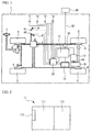
FIG. 1 , anelectric drive vehicle 1 is equipped with apower generating unit 11, abattery 12, and anelectric motor 13. Thepower generating unit 11 is detachably installed in theelectric drive vehicle 1. Theelectric drive vehicle 1 with thepower generating unit 11 being detachably installed can operate even in a state in which thepower generating unit 11 is not installed and an electric connection with thepower generating unit 11 is not made. Thepower generating unit 11 may charge thebattery 12 even when thepower generating unit 11 is not installed in theelectric drive vehicle 1 as long as thepower generating unit 11 is electrically connected to theelectric drive vehicle 1. - The
power generating unit 11 is an engine driven type of power generating unit. As illustrated inFIG. 2 , thepower generating unit 11 is equipped with anengine 111. agenerator 112, and a power generating unit side ECU (Electronic Control Unit) 113. Theengine 111 drives thegenerator 112, which generates alternating current. The alternating current thus generated is converted to direct current by a not-illustrated rectifier circuit before being stored in thebattery 12. The ECU 113 on the power generating unit side is provided for primarily controlling theengine 111. - The
battery 12 is a DC battery and is electrically and detachably connected to thepower generating unit 11 via a high-voltage-system wiring, which is a power wiring. Power generated by thepower generating unit 11 is charged in thebattery 12 via the high-voltage-system wiring. Thebattery 12 may be configured to have multiple batteries having a rated voltage of 12 V connected in series. Theelectric motor 13 is a driving source and is a DC motor. Theelectric motor 13 is supplied with power from thebattery 12 and rotates anoutput shaft 14. The rotary output is transmitted, via atransmission 15, to a pair of right and leftrear wheels 2, which are driving wheels, so that therear wheels 2 can be driven. As described above, theelectric drive vehicle 1 is a series hybrid type of electric drive vehicle. - The
electric drive vehicle 1 is equipped, in addition to the pair of right and leftrear wheels 2 of the driving wheels, with a pair of right and leftfront wheels 3 that are steering wheels, ahandle 4 for manually steering thefront wheels 3, anacceleration pedal 5 for changing the number of revolutions of theelectric motor 13, abrake pedal 6 and abrake unit 7 for braking the vehicle, anddrum brakes 8 coupled with thebrake pedal 6 by wires, joined to thebrake unit 7 and provided to thefront wheels 2 and therear wheels 3. Theacceleration pedal 5 is provided with an acceleration position sensor 61 that the degree of depression of theacceleration pedal 5, and thebrake pedal 6 is provided with abrake switch 62 that senses whether thebrake pedal 6 is depressed or not. - Further, the
electric derive vehicle 1 is equipped with anexternal charging unit 20. Theexternal charging unit 20 is a device for charging thebattery 12 from anexternal power supply 40. Theexternal charging unit 20 is configured to enable communications by a power line communication (PLC) and has a function of determining whether theexternal power supply 40 has been connected to theexternal charging unit 20 or not. Theexternal charging unit 20 is connected to theexternal power supply 40 via acharging cable 30. More specifically, theexternal power supply 40 may, for example, be a 100V power supply, a 200V power supply or fast charging equipment. - Further, the
electric drive vehicle 1 is equipped with akey switch 71. a parallelcharging request switch 72, a fastcharging request switch 73, and anoperation panel 74. Thekey switch 71 is an operation means capable of selecting whether to operate theelectric motor 13. The parallelcharging request switch 72 is an operation means capable of selecting whether parallel charging of thebattery 12 by both theexternal power supply 40 and thepower generating unit 11 should be done and an operation means for making a parallel charging request. The fastcharging request switch 73 is an operation means capable of selecting whether to generate power so that priority is given to the charge capacity of the power generatingunit 11 during parallel charging and is an operation means for making a fast charging request. Theoperation panel 74 is an operation means capable of specifying various settings regarding charging thebattery 12. Theseswitches operation panel 74 are provided on a not-illustrated instrument panel. - The
electric drive vehicle 1 is further provided with a vehicle-side ECU 50, which is a first control device. The vehicle-side ECU 50 is equipped with a microcomputer including a CPU, a ROM, and a RAM, and an input/output circuit, which are not illustrated. The ECU 113 on the power generating side, which is a second control device, is configured similarly. The power generating unit 11 (more particularly, the ECU 113 on the power generating unit side) is electrically and detachably connected to the vehicle-side ECU 50. In this regard, more specifically, the vehicle-side ECU 50 and thepower generating unit 11 are connected together via a low-voltage-system wiring, which is a control-system wiring. Various objects to be controlled such as theelectric motor 13 are electrically connected to the vehicle-side ECU 50, and various sensors and switches such as the acceleration position sensor 61, thebrake switch 62, thekey switch 71, the parallelcharging request switch 73, and theoperation panel 74. - The
external charging unit 20 is connected to the vehicle-side ECU 50 in order to detect whether theexternal power supply 40 has been connected, and thebattery 12 is also connected thereto in order to detect the quantity of charge stored therein. Further, an ammeter and a voltmeter, which are not illustrated, are connected to the vehicle-side ECU 50 in order to detect power supplied from theexternal power supply 40. The vehicle-side ECU 50 detects power supplied from theexternal power supply 40 on the basis of detected values af the ammeter and the voltmeter. Alternatively, the vehicle-side ECU 50 may be notified of the current that can be supplied by theexternal power supply 40, the voltage of theexternal power supply 40 and the power that can be supplied by theexternal power supply 40 by, for example, theexternal power supply 40 by using the power line communication. Further, other means may be employed in order to implement the detection and notification. - The ROM is configured to store a program in which various processes executed by the CPU are described and to store map data. The CPU executes the processes on the basis of the program stored in the ROM while using a temporary memory area ensured in the RAM as necessary, so that various control means, determination means, detection means and calculation means can be functionally realized in the
ECU 50 on the vehicle side and theECU 113 on the power generating unit side. - For example, the vehicle-
side ECU 50 functionally realizes a control means that permits thebattery 12 to be charged by thepower generating unit 11 in a case where power supplied from theexternal power supply 40 is smaller than a predetermined threshold value α, which is defined with regard to an acceptable power W of thebattery 12. - The predetermined threshold value α is a value used to determine whether the parallel charging is permitted or not on the basis of the power capacity of the
external power supply 40. In the present embodiment, the predetermined threshold value α is larger than power that can be supplied from a 100V power supply and is smaller than powers respectively supplied from a 200V power supply and the fast charging equipment. - The control means is realized so as to permit the
battery 12 to be charged by thepower generating unit 11 in a case where power supplied from theexternal powder supply 40 is smaller than the predetermined threshold value α and the parallelcharging request switch 72 is operated so as to execute the parallel charging (in a case where the parallel charging request has been issued). - The vehicle-
side ECU 50 functionally realizes a management means that manages power supplied to thebattery 12 in charging of thepattern 12. - In this regard, the management means is realized so as to manage power supplied from at least the
power generating unit 11 among power supplied from theexternal power supply 40 and power supplied from thepower generating unit 11. - In the management of power supplied from the
power generating unit 11, the management means is realized to execute a control for operating theengine 111 at a fast charging operating point at which theengine 111 can operate at the maximum output or at an optimal fuel economy operating point at which theengine 111 can operate with an optimal fuel economy on the basis of the capacities of thepower generating unit 11 and theexternal power supply 40 and the presence or absence of the fast charging request, or is realized to execute another control for operating theengine 111 so as to make up power corresponding to the difference between the acceptable power W of thebattery 12 and the power that can be supplied by the external power supply 40 (hereinafter, the later control is referred to as a power make-up control). - In execution of the above controls, more particularly, the management means is realized to determine whether the sum of the power supplied from the
external powder supply 40 and the power supplied from thepower generating unit 11 in the state where theengine 111 is operated at the fast charging operating point is smaller than the acceptable power W of the battery 12 (hereinafter, the above sum is referred to as first sum). - When the first sum is smaller than the acceptable power W of the
battery 12 and the fast charging request has been issued, the management means is realized to execute the control that operates theengine 111 at the fast charging operating point. - When the first sum is smaller than the acceptable power W of the
battery 12 and the fast charging request has not been issued, the management means is realized to execute the control that operates theengine 111 at the optimal fuel economy operating point. - When the first sum is equal to or larger than the acceptable power W of the
battery 12, the management means determines whether the sum of the power supplied from theexternal power supply 40 and the power supplied from thepower generating unit 11 in a case where theengine 111 is operated at the optimal fuel economy operating point is smaller than the acceptable power W of the battery (hereinafter, the above sum is referred to as second sum). - When the second sum is smaller than the acceptable power W of the
battery 12 and the fast charging request has not been issued, the management means is realized to execute the control that operates theengine 111 at the optimal fuel economy operating point. - When the second sum is smaller than the acceptable power W of the
battery 12 and the fast charging request has been issued, the management means is realized to execute the power make-up control. - When the second sum is equal to or larger than the acceptable power W of the
battery 12, the management means is realized to execute the power make-up control regardless of whether the fast charging request has been issued. - The management means may be configured to execute the control to operate the
engine 111 in an operating condition arranged to give priority to the charge capacity when the fast charging request, for example, is issued as the power make-up control and to execute the control to operate theengine 111 in another operating condition arranged to give priority to the fuel economy when the fast charging request is not issued. - In the management of power supplied from the
power generating unit 11, the management means is realized to execute management that depends on the progress of charging. For example, the management means is realized to stop the operation of theengine 111 in a case where the state of charge of thebattery 12 becomes larger than a predetermined value β (for example, 80%). For example, the management means is realized to stop theengine 111 in a state in which charging of thebattery 12 can be completed by power supplied from theexternal power supply 40 within a requested charging time γ necessary to complete charging of the battery 12 (hereinafter, such a state is referred to as parallel charging unneeded state). In a case where the predetermined value β or the requested charge time γ is not set, the management means is realized to stop theengine 111 when charging of thebattery 12 is complete. The predetermined value β and the requested charge time γ may be set on theoperation panel 74. - Now, a description is given, with reference to flowcharts of
FIGS. 3 and4 , of an operation of the vehicle-side ECU 50. As illustrated inFIG. 3 , the vehicle-side ECU 50 determines whether theexternal power supply 40 has been connected (step S1). When a negative decision is made at step S1, no process is needed and the present flow is ended. In contrast, when an affirmative decision is made at step S1, the vehicle-side ECU 50 determines whether power supplied from the external power supply 40 (the capacity of the external power supply) is smaller than the predetermined threshold value α (step S2). When a negative decision is made a step S2, the vehicle-side ECU 50 stops the engine 111 (step S11). At that time, theengine 111 may already be stopped. In this case, thebattery 12 is charged by theexternal powder supply 40 only. - In contrast, when an affirmative decision is made at step S2, the vehicle-
side ECU 50 determines whether the parallel charging request is issued (step S3). When a negative decision is made at step S3, the process proceeds to step S11. In contrast, when an affirmative decision is made at step S3, the vehicle-side ECU 50 determines whether the first sum is smaller than the acceptable power W of the battery 12 (step S4). When an affirmative decision is made, the vehicle-side ECU 50 determines whether the fast charging request is issued (step S5). When an affirmative decision is made, the vehicle-side ECU 50 operates theengine 111 at the fast charging operating point (step S8). In contrast, when a negative decision is made at step S5, the vehicle-side ECU 50 operates theengine 111 at the optimal fuel economy operating point (step S9). - In contrast, when a negative decision is made at step S4, the vehicle-
side ECU 50 determines whether the second sum is smaller than the acceptable power W of the battery 12 (step S6). When an affirmative decision is made, the vehicle-side ECU 50 determines whether no fast charging request is issued (step S7). When it is determined that no fast charging request is issued, the vehicle-side ECU 50 operates theengine 111 at the optimal fuel economy operating point (step S9). In contrast, when it is determined that the fast charging request is issued, the vehicle-side ECU 50 executes the power make-up control (step S10). In theelectric drive vehicle 1, the parallel charging is executed as described above when the process proceeds to step S8, S9 or S10. - When the parallel charging is carried out, as illustrated in
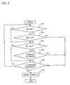
FIG. 4 , the vehicle-side ECU 50 further determines whether the predetermined value β has been set (step 21). When an affirmative decision is made, the vehicle-side ECU 50 determines whether the state of charge (SOC) is larger than the predetermined value β (step S22). When an affirmative decision is made, the vehicle-side ECU 50 stops the engine 111 (step S26). In contrast, when a negative decision is made at step S21 or S22, the vehicle-side ECU 50 determines whether the requested charge time γ has been set (step S23). When an affirmative decision is made, the vehicle-side ECU 50 determines whether the vehicle falls in the parallel charging unneeded state (step S24). A decision as to whether the vehicle falls in the parallel charging unneeded state may be made on the basis of, for example, the acceptable power W of thebattery 12, powers respectively supplied from thepower generating unit 11 and theexternal power supply 40, the current charged battery capacity, the requested charging time γ and the remaining time for charging. - When an affirmative decision is made at step S24, the vehicle-
side ECU 50 stops the engine 111 (step S26). On the contrary, when a negative decision is made at step S23 or S24, the vehicle-side ECU 50 determines whether charging thebattery 12 is completed (step S25). When a negative decision is made, the process returns to step S21. When an affirmative decision is made at step S25, the vehicle-side ECU 50 stops the engine 111 (step S26). - A description is given of functions and effects of the
electric drive vehicle 1. In a case where power supplied from theexternal power supply 40 is smaller than the predetermined threshold value α, the electric drive vehicle I is configured to permit thebattery 12 to be charged by thepower generating unit 11. Thus, in theelectric drive vehicle 1, it is possible to charge thebattery 12 by the multiple power supplies including thepower generating unit 11 and theexternal power supply 40. Thus, theelectric drive vehicle 1 is capable of more quickly charging thebattery 12 even in an exemplary case where an external power supply having a small power supply capacity is utilized as theexternal power supply 40. - In the
electric drive vehicle 1, charging of thebattery 12 by thepower generating unit 11 is permitted when the parallel charging request is issued. Thus, the electric drive vehicle I is configured to prevent uneconomical charging of thebattery 12 against the user's will due to parallel charging of thebattery 12 by thepower generating unit 11. - The
electric drive vehicle 1 is configured to operate theengine 111 at the fast charging operating point or the optimal fuel economy operating point on the basis of the power supply capacities of thepower generating unit 11 and theexternal power supply 40 and the presence/absence of the fast charging request when the parallel charging is carried out. Thus, in theelectric drive vehicle 1, faster charging is realized by operating theengine 111 at the fast charging operating point when the user issues the fast charging request, and economical charging is realized by operating theengine 111 at the optimal fuel economy operating point when the fast charging request is not issued. - Further, the
electric drive vehicle 1 is configured to quickly charge thebattery 12 by the parallel charging implemented by the power make-up control even when the power supply capacities of thepower generating unit 11 and theexternal power supply 40 are not enough to operate theengine 111 at the fast charging operating point or the optimal fuel economy operating point. - The
electric drive vehicle 1 is configured to stop theengine 111 when the state of charge of the battery exceeds the predetermined value β in parallel charging. Thus, in theelectric drive vehicle 1, the battery can be quickly charged up to a minimum state of charge of the battery by parallel charging, and thereafter, can be charged more economically by charging by only theexternal power supply 40 to gain a further state of charge over the minimum state of charge. - The
electric drive vehicle 1 is configured to stop theengine 111 when the vehicle falls in the parallel charging unneeded state in parallel charging. In theelectric drive vehicle 1, it is possible to prevent thepower generating unit 11 from generating more power than is needed in order to complete charging of thebattery 12 and realize more economical charging. - The above-described embodiment is an exemplary preferable embodiment. The present invention is not limited to the embodiment but various embodiments and variations for carrying out the invention may be made.
- For example, the above-described embodiment is the
electric drive vehicle 1 that is a series hybrid type of electric drive vehicle. However, the present invention is not limited to the above but may be a parallel hybrid type of electric drive vehicle in which both the engine and the electric motor can drive the driving wheels concurrently. - In the above-described embodiment, the
power generating unit 11, which is detachably installed in theelectric drive vehicle 1, is an electric generator. However, the present invention is not limited to the above but the power generating unit capable of charging the battery may be a power generating unit other than the power generating unit detachably installed in the electric drive vehicle. - The above-described embodiment is directed to the case where the predetermined threshold value α is larger than the power that can be supplied from the 100 V power supply and is smaller than the power that can be supplied by the 200V power supply and the fast charging equipment.
- However, the present invention is not limited to the above, but the threshold value may be larger than the power that can be supplied by the 200V power supply and is smaller than the power that can be supplied by the fast charging equipment.
- In this regard, the acceptable power of the battery may be equal to or greater than the power that can be supplied by the fast charging equipment. In this case, the predetermined threshold value may be equal to or larger than the power that can be supplied by the fast charging equipment and may be equal to or smaller than the acceptable power of the battery.
- In the above-described embodiment, the management means is realized so as to manage the power supplied from the
power generating unit 11. However, the present invention is not limited to the above, but the management means may further manage power supplied from theexternal power supply 40. In this regard, for example, the management means may be realized to the distribution of power supplied from the external power supply and power supplied from the power generating unit. - More particularly, in an exemplary case where the rates of power supplied from the external power supply are different in different time zones, based on time zone information about the power rates, the ratio of power from the external power supply is increased in a time zone in which the power rates are comparatively low rather than another time zone in which the power rates are comparatively high, while the power supplied from the power generating unit is decreased and may be decreased to zero so that the engine is stopped.
- In this case, based on the residual quantity of fuel used for the engine of the power generating unit, it is possible to increase the ratio of power supplied from the external power supply when the residual quantity of fuel becomes a predetermined value, while the power supplied from the power generating unit is decreased and may be decreased to zero so that the engine is stopped.
- In a case where the ratio of power supplied from the power generating unit is decreased, it is possible to cause the engine that is operating at the fast charging operating point to operate at the optimal fuel economy operating point, or to stop the engine that is operating at the optimal fuel economy operating point.
- The various means functionally realized by the vehicle-
side ECU 50 employed in the above-described embodiment may be realized by, for example, other electronic control devices, hardware such as dedicated electronic circuits or combination thereof. -
- 1
- Electric drive engine
- 11
- Power generating unit
- 111
- Engine
- 12
- Battery
- 13
- Electric motor
- 20
- External charging unit
- 30
- Charging cable
- 40
- External power supply
- 50
- Vehicle side ECU
- 71
- Key switch
- 72
- Parallel charging request switch
- 73
- Fast charging request switch
- 74
- Operation panel
Claims (3)
- An electric drive vehicle equipped with a battery usable for traveling and chargeable by an external power supply, comprising
control means for permitting the battery to be charged by a power generating unit capable of charging the battery in a case where power supplied from the external power supply is smaller than a predetermined threshold value that is defined with regard to an acceptable power of the battery. - The electric drive vehicle according to claim 1, further comprising operation means capable of selecting whether parallel charging of the battery by both the external power supply and the power generating unit should be done,
wherein the control means permits the battery to be charged by the power generating unit in a case where the power supplied from the external power supply is smaller than the predetermined threshold value and the parallel charging is selected via the operation means. - The electric drive vehicle according to claim 1 or 2, further comprising management means for managing power supplied from at least the power generating unit among the power supplied from the external power supply and the power supplied from the power generating unit.
Applications Claiming Priority (1)
| Application Number | Priority Date | Filing Date | Title |
|---|---|---|---|
| PCT/JP2009/069262 WO2011058630A1 (en) | 2009-11-12 | 2009-11-12 | Electrically driven vehicle |
Publications (3)
| Publication Number | Publication Date |
|---|---|
| EP2402204A1 true EP2402204A1 (en) | 2012-01-04 |
| EP2402204A4 EP2402204A4 (en) | 2014-03-05 |
| EP2402204B1 EP2402204B1 (en) | 2016-01-06 |
Family
ID=43991309
Family Applications (1)
| Application Number | Title | Priority Date | Filing Date |
|---|---|---|---|
| EP09848581.6A Not-in-force EP2402204B1 (en) | 2009-11-12 | 2009-11-12 | Electrically driven vehicle |
Country Status (5)
| Country | Link |
|---|---|
| US (1) | US8872470B2 (en) |
| EP (1) | EP2402204B1 (en) |
| JP (1) | JP4775522B2 (en) |
| CN (1) | CN102438853B (en) |
| WO (1) | WO2011058630A1 (en) |
Cited By (1)
| Publication number | Priority date | Publication date | Assignee | Title |
|---|---|---|---|---|
| WO2014177332A2 (en) * | 2013-05-02 | 2014-11-06 | Robert Bosch Gmbh | Device and method for operating an energy storage arrangement of a motor vehicle |
Families Citing this family (7)
| Publication number | Priority date | Publication date | Assignee | Title |
|---|---|---|---|---|
| JP5246383B2 (en) * | 2010-08-24 | 2013-07-24 | ソニー株式会社 | Transmitting apparatus, receiving apparatus, and communication system |
| US8810053B2 (en) * | 2012-02-29 | 2014-08-19 | Ini Power Systems, Inc. | Method and apparatus for efficient fuel consumption |
| JP5839697B2 (en) | 2012-04-26 | 2016-01-06 | 日立建機株式会社 | Operation management system |
| USD827572S1 (en) | 2015-03-31 | 2018-09-04 | Ini Power Systems, Inc. | Flexible fuel generator |
| US10030609B2 (en) | 2015-11-05 | 2018-07-24 | Ini Power Systems, Inc. | Thermal choke, autostart generator system, and method of use thereof |
| JP2018033314A (en) * | 2016-04-05 | 2018-03-01 | 三菱重工業株式会社 | Electric car and charger |
| US10279695B2 (en) * | 2016-08-08 | 2019-05-07 | Hyundai Motor Company | Electric vehicle parallel charging method and apparatus |
Citations (3)
| Publication number | Priority date | Publication date | Assignee | Title |
|---|---|---|---|---|
| US20080238355A1 (en) * | 2007-03-26 | 2008-10-02 | Yamaha Hatsudoki Kabushiki Kaisha | Fuel cell system and operation method therefor |
| WO2009051185A1 (en) * | 2007-10-19 | 2009-04-23 | Toyota Jidosha Kabushiki Kaisha | External charging electric/hybrid vehicle |
| US20090250277A1 (en) * | 2007-01-12 | 2009-10-08 | Grand Kerry E | Battery Equalization Using a Plug-In Charger in a Hybrid Electric Vehicle |
Family Cites Families (16)
| Publication number | Priority date | Publication date | Assignee | Title |
|---|---|---|---|---|
| JPS557045B2 (en) * | 1974-02-05 | 1980-02-21 | ||
| JPS557764B2 (en) * | 1974-02-23 | 1980-02-28 | ||
| JPH10155205A (en) | 1996-11-22 | 1998-06-09 | Yamaha Motor Co Ltd | Electrically driven vehicle |
| JPH10290533A (en) * | 1997-04-14 | 1998-10-27 | Honda Motor Co Ltd | Battery charging system |
| JPH11178109A (en) * | 1997-12-04 | 1999-07-02 | Toyota Motor Corp | Hybrid driver |
| US6321707B1 (en) * | 1998-11-12 | 2001-11-27 | James Dunn | Multifunction auxiliary vehicle power and starter system |
| JP4132382B2 (en) * | 1999-04-09 | 2008-08-13 | 富士重工業株式会社 | Battery charger for electric vehicles |
| US7348760B2 (en) * | 2000-09-21 | 2008-03-25 | O2Micro International Limited | Power management topologies |
| RU2294851C2 (en) * | 2001-04-05 | 2007-03-10 | Электровайа Инк. | Device for storing and supply of variable power consumers |
| JP2003004822A (en) * | 2001-06-15 | 2003-01-08 | Matsushita Electric Ind Co Ltd | Battery power source device |
| JP2003176748A (en) * | 2001-12-11 | 2003-06-27 | Araco Corp | Hybrid vehicle |
| JP2004088979A (en) * | 2002-08-29 | 2004-03-18 | Aichi Corp | Charge operation controller for vehicle |
| JP3896973B2 (en) * | 2003-02-25 | 2007-03-22 | 株式会社デンソー | Management method of electric system for vehicle |
| US7240653B2 (en) * | 2005-10-31 | 2007-07-10 | Caterpillar Inc | System for assisting a main engine start-up |
| CN101150259B (en) * | 2006-09-18 | 2010-05-12 | 比亚迪股份有限公司 | Electric car charging system |
| JP4816650B2 (en) | 2008-01-10 | 2011-11-16 | 株式会社デンソー | Power supply control device and program for power supply control device |
-
2009
- 2009-11-12 WO PCT/JP2009/069262 patent/WO2011058630A1/en active Application Filing
- 2009-11-12 EP EP09848581.6A patent/EP2402204B1/en not_active Not-in-force
- 2009-11-12 CN CN200980133179.5A patent/CN102438853B/en not_active Expired - Fee Related
- 2009-11-12 US US13/057,088 patent/US8872470B2/en not_active Expired - Fee Related
- 2009-11-12 JP JP2011504272A patent/JP4775522B2/en not_active Expired - Fee Related
Patent Citations (3)
| Publication number | Priority date | Publication date | Assignee | Title |
|---|---|---|---|---|
| US20090250277A1 (en) * | 2007-01-12 | 2009-10-08 | Grand Kerry E | Battery Equalization Using a Plug-In Charger in a Hybrid Electric Vehicle |
| US20080238355A1 (en) * | 2007-03-26 | 2008-10-02 | Yamaha Hatsudoki Kabushiki Kaisha | Fuel cell system and operation method therefor |
| WO2009051185A1 (en) * | 2007-10-19 | 2009-04-23 | Toyota Jidosha Kabushiki Kaisha | External charging electric/hybrid vehicle |
Non-Patent Citations (1)
| Title |
|---|
| See also references of WO2011058630A1 * |
Cited By (2)
| Publication number | Priority date | Publication date | Assignee | Title |
|---|---|---|---|---|
| WO2014177332A2 (en) * | 2013-05-02 | 2014-11-06 | Robert Bosch Gmbh | Device and method for operating an energy storage arrangement of a motor vehicle |
| WO2014177332A3 (en) * | 2013-05-02 | 2015-04-09 | Robert Bosch Gmbh | Device and method for operating an energy storage arrangement of a motor vehicle |
Also Published As
| Publication number | Publication date |
|---|---|
| CN102438853B (en) | 2014-12-17 |
| WO2011058630A1 (en) | 2011-05-19 |
| US20120091790A1 (en) | 2012-04-19 |
| US8872470B2 (en) | 2014-10-28 |
| CN102438853A (en) | 2012-05-02 |
| EP2402204B1 (en) | 2016-01-06 |
| JP4775522B2 (en) | 2011-09-21 |
| JPWO2011058630A1 (en) | 2013-03-28 |
| EP2402204A4 (en) | 2014-03-05 |
Similar Documents
| Publication | Publication Date | Title |
|---|---|---|
| EP2402204B1 (en) | Electrically driven vehicle | |
| JP4434302B2 (en) | Hybrid vehicle control device and hybrid vehicle | |
| JP5382238B2 (en) | Hybrid vehicle and control method thereof | |
| JP4306746B2 (en) | Vehicle power supply | |
| CN102958775B (en) | The control setup of motor vehicle driven by mixed power and there is the motor vehicle driven by mixed power of this control setup | |
| CN110315976B (en) | Vehicle power supply system | |
| CN103879400A (en) | Traveling mode switching controller of hybrid electric vehicle | |
| CN104903171B (en) | Method for the energy of the acceleration boosting torque that reduces motor vehicle driven by mixed power | |
| CN110316019B (en) | Vehicle power supply system | |
| JPWO2012169009A1 (en) | Electric vehicle and control method of electric vehicle | |
| CN102883934A (en) | Hybrid vehicle control device and hybrid vehicle provided with same | |
| JP7081958B2 (en) | Vehicle power system | |
| CN110315999B (en) | Vehicle power supply system | |
| US20140039743A1 (en) | Electric vehicle and method for controlling speed thereof | |
| KR20120012654A (en) | Electric vehicle and method for controlling the same | |
| KR20120063313A (en) | Battery management apparatus for electric automobile and method thereof | |
| US10926661B2 (en) | Transient battery power management | |
| JP2013106457A (en) | Output characteristic control method | |
| US10569656B2 (en) | Regenerative control device | |
| CN106605028B (en) | Hybrid construction machine | |
| US9434378B2 (en) | System and method for improving the vehicle feel, fuel efficiency and performance of a hybrid vehicle | |
| EP3704011A1 (en) | Electric drive vehicle | |
| JP6270010B2 (en) | Vehicle power control device | |
| KR100440117B1 (en) | Battery charge controlling method of hybrid vehicle | |
| JP7038580B2 (en) | Vehicle power system |
Legal Events
| Date | Code | Title | Description |
|---|---|---|---|
| PUAI | Public reference made under article 153(3) epc to a published international application that has entered the european phase |
Free format text: ORIGINAL CODE: 0009012 |
|
| AK | Designated contracting states |
Kind code of ref document: A1 Designated state(s): AT BE BG CH CY CZ DE DK EE ES FI FR GB GR HR HU IE IS IT LI LT LU LV MC MK MT NL NO PL PT RO SE SI SK SM TR |
|
| 17P | Request for examination filed |
Effective date: 20110301 |
|
| DAX | Request for extension of the european patent (deleted) | ||
| RAP1 | Party data changed (applicant data changed or rights of an application transferred) |
Owner name: TOYOTA JIDOSHA KABUSHIKI KAISHA |
|
| A4 | Supplementary search report drawn up and despatched |
Effective date: 20140205 |
|
| RIC1 | Information provided on ipc code assigned before grant |
Ipc: B60L 11/02 20060101ALI20140130BHEP Ipc: B60L 11/18 20060101AFI20140130BHEP Ipc: B60K 6/46 20071001ALI20140130BHEP Ipc: B60W 50/08 20120101ALI20140130BHEP Ipc: B60W 10/06 20060101ALI20140130BHEP Ipc: B60W 10/26 20060101ALI20140130BHEP Ipc: B60W 20/00 20060101ALI20140130BHEP Ipc: H02J 7/00 20060101ALI20140130BHEP Ipc: B60L 11/12 20060101ALI20140130BHEP Ipc: B60W 10/08 20060101ALI20140130BHEP |
|
| GRAP | Despatch of communication of intention to grant a patent |
Free format text: ORIGINAL CODE: EPIDOSNIGR1 |
|
| INTG | Intention to grant announced |
Effective date: 20150630 |
|
| GRAS | Grant fee paid |
Free format text: ORIGINAL CODE: EPIDOSNIGR3 |
|
| GRAA | (expected) grant |
Free format text: ORIGINAL CODE: 0009210 |
|
| AK | Designated contracting states |
Kind code of ref document: B1 Designated state(s): AT BE BG CH CY CZ DE DK EE ES FI FR GB GR HR HU IE IS IT LI LT LU LV MC MK MT NL NO PL PT RO SE SI SK SM TR |
|
| REG | Reference to a national code |
Ref country code: GB Ref legal event code: FG4D |
|
| REG | Reference to a national code |
Ref country code: CH Ref legal event code: EP |
|
| REG | Reference to a national code |
Ref country code: IE Ref legal event code: FG4D |
|
| REG | Reference to a national code |
Ref country code: AT Ref legal event code: REF Ref document number: 768560 Country of ref document: AT Kind code of ref document: T Effective date: 20160215 |
|
| REG | Reference to a national code |
Ref country code: DE Ref legal event code: R096 Ref document number: 602009035750 Country of ref document: DE |
|
| REG | Reference to a national code |
Ref country code: LT Ref legal event code: MG4D |
|
| REG | Reference to a national code |
Ref country code: NL Ref legal event code: MP Effective date: 20160106 |
|
| REG | Reference to a national code |
Ref country code: AT Ref legal event code: MK05 Ref document number: 768560 Country of ref document: AT Kind code of ref document: T Effective date: 20160106 |
|
| PG25 | Lapsed in a contracting state [announced via postgrant information from national office to epo] |
Ref country code: NL Free format text: LAPSE BECAUSE OF FAILURE TO SUBMIT A TRANSLATION OF THE DESCRIPTION OR TO PAY THE FEE WITHIN THE PRESCRIBED TIME-LIMIT Effective date: 20160106 |
|
| PG25 | Lapsed in a contracting state [announced via postgrant information from national office to epo] |
Ref country code: HR Free format text: LAPSE BECAUSE OF FAILURE TO SUBMIT A TRANSLATION OF THE DESCRIPTION OR TO PAY THE FEE WITHIN THE PRESCRIBED TIME-LIMIT Effective date: 20160106 Ref country code: FI Free format text: LAPSE BECAUSE OF FAILURE TO SUBMIT A TRANSLATION OF THE DESCRIPTION OR TO PAY THE FEE WITHIN THE PRESCRIBED TIME-LIMIT Effective date: 20160106 Ref country code: GR Free format text: LAPSE BECAUSE OF FAILURE TO SUBMIT A TRANSLATION OF THE DESCRIPTION OR TO PAY THE FEE WITHIN THE PRESCRIBED TIME-LIMIT Effective date: 20160407 Ref country code: IT Free format text: LAPSE BECAUSE OF FAILURE TO SUBMIT A TRANSLATION OF THE DESCRIPTION OR TO PAY THE FEE WITHIN THE PRESCRIBED TIME-LIMIT Effective date: 20160106 Ref country code: ES Free format text: LAPSE BECAUSE OF FAILURE TO SUBMIT A TRANSLATION OF THE DESCRIPTION OR TO PAY THE FEE WITHIN THE PRESCRIBED TIME-LIMIT Effective date: 20160106 Ref country code: NO Free format text: LAPSE BECAUSE OF FAILURE TO SUBMIT A TRANSLATION OF THE DESCRIPTION OR TO PAY THE FEE WITHIN THE PRESCRIBED TIME-LIMIT Effective date: 20160406 |
|
| PG25 | Lapsed in a contracting state [announced via postgrant information from national office to epo] |
Ref country code: PT Free format text: LAPSE BECAUSE OF FAILURE TO SUBMIT A TRANSLATION OF THE DESCRIPTION OR TO PAY THE FEE WITHIN THE PRESCRIBED TIME-LIMIT Effective date: 20160506 Ref country code: AT Free format text: LAPSE BECAUSE OF FAILURE TO SUBMIT A TRANSLATION OF THE DESCRIPTION OR TO PAY THE FEE WITHIN THE PRESCRIBED TIME-LIMIT Effective date: 20160106 Ref country code: LT Free format text: LAPSE BECAUSE OF FAILURE TO SUBMIT A TRANSLATION OF THE DESCRIPTION OR TO PAY THE FEE WITHIN THE PRESCRIBED TIME-LIMIT Effective date: 20160106 Ref country code: SE Free format text: LAPSE BECAUSE OF FAILURE TO SUBMIT A TRANSLATION OF THE DESCRIPTION OR TO PAY THE FEE WITHIN THE PRESCRIBED TIME-LIMIT Effective date: 20160106 Ref country code: PL Free format text: LAPSE BECAUSE OF FAILURE TO SUBMIT A TRANSLATION OF THE DESCRIPTION OR TO PAY THE FEE WITHIN THE PRESCRIBED TIME-LIMIT Effective date: 20160106 Ref country code: IS Free format text: LAPSE BECAUSE OF FAILURE TO SUBMIT A TRANSLATION OF THE DESCRIPTION OR TO PAY THE FEE WITHIN THE PRESCRIBED TIME-LIMIT Effective date: 20160506 Ref country code: LV Free format text: LAPSE BECAUSE OF FAILURE TO SUBMIT A TRANSLATION OF THE DESCRIPTION OR TO PAY THE FEE WITHIN THE PRESCRIBED TIME-LIMIT Effective date: 20160106 |
|
| REG | Reference to a national code |
Ref country code: DE Ref legal event code: R084 Ref document number: 602009035750 Country of ref document: DE |
|
| REG | Reference to a national code |
Ref country code: GB Ref legal event code: 746 Effective date: 20160905 |
|
| REG | Reference to a national code |
Ref country code: DE Ref legal event code: R097 Ref document number: 602009035750 Country of ref document: DE |
|
| REG | Reference to a national code |
Ref country code: FR Ref legal event code: PLFP Year of fee payment: 8 |
|
| PG25 | Lapsed in a contracting state [announced via postgrant information from national office to epo] |
Ref country code: DK Free format text: LAPSE BECAUSE OF FAILURE TO SUBMIT A TRANSLATION OF THE DESCRIPTION OR TO PAY THE FEE WITHIN THE PRESCRIBED TIME-LIMIT Effective date: 20160106 Ref country code: EE Free format text: LAPSE BECAUSE OF FAILURE TO SUBMIT A TRANSLATION OF THE DESCRIPTION OR TO PAY THE FEE WITHIN THE PRESCRIBED TIME-LIMIT Effective date: 20160106 |
|
| PLBE | No opposition filed within time limit |
Free format text: ORIGINAL CODE: 0009261 |
|
| STAA | Information on the status of an ep patent application or granted ep patent |
Free format text: STATUS: NO OPPOSITION FILED WITHIN TIME LIMIT |
|
| PG25 | Lapsed in a contracting state [announced via postgrant information from national office to epo] |
Ref country code: CZ Free format text: LAPSE BECAUSE OF FAILURE TO SUBMIT A TRANSLATION OF THE DESCRIPTION OR TO PAY THE FEE WITHIN THE PRESCRIBED TIME-LIMIT Effective date: 20160106 Ref country code: RO Free format text: LAPSE BECAUSE OF FAILURE TO SUBMIT A TRANSLATION OF THE DESCRIPTION OR TO PAY THE FEE WITHIN THE PRESCRIBED TIME-LIMIT Effective date: 20160106 Ref country code: SK Free format text: LAPSE BECAUSE OF FAILURE TO SUBMIT A TRANSLATION OF THE DESCRIPTION OR TO PAY THE FEE WITHIN THE PRESCRIBED TIME-LIMIT Effective date: 20160106 Ref country code: SM Free format text: LAPSE BECAUSE OF FAILURE TO SUBMIT A TRANSLATION OF THE DESCRIPTION OR TO PAY THE FEE WITHIN THE PRESCRIBED TIME-LIMIT Effective date: 20160106 |
|
| 26N | No opposition filed |
Effective date: 20161007 |
|
| PG25 | Lapsed in a contracting state [announced via postgrant information from national office to epo] |
Ref country code: BE Free format text: LAPSE BECAUSE OF FAILURE TO SUBMIT A TRANSLATION OF THE DESCRIPTION OR TO PAY THE FEE WITHIN THE PRESCRIBED TIME-LIMIT Effective date: 20160106 |
|
| PG25 | Lapsed in a contracting state [announced via postgrant information from national office to epo] |
Ref country code: SI Free format text: LAPSE BECAUSE OF FAILURE TO SUBMIT A TRANSLATION OF THE DESCRIPTION OR TO PAY THE FEE WITHIN THE PRESCRIBED TIME-LIMIT Effective date: 20160106 Ref country code: BG Free format text: LAPSE BECAUSE OF FAILURE TO SUBMIT A TRANSLATION OF THE DESCRIPTION OR TO PAY THE FEE WITHIN THE PRESCRIBED TIME-LIMIT Effective date: 20160406 |
|
| REG | Reference to a national code |
Ref country code: CH Ref legal event code: PL |
|
| PG25 | Lapsed in a contracting state [announced via postgrant information from national office to epo] |
Ref country code: LI Free format text: LAPSE BECAUSE OF NON-PAYMENT OF DUE FEES Effective date: 20161130 Ref country code: CH Free format text: LAPSE BECAUSE OF NON-PAYMENT OF DUE FEES Effective date: 20161130 |
|
| REG | Reference to a national code |
Ref country code: IE Ref legal event code: MM4A |
|
| PG25 | Lapsed in a contracting state [announced via postgrant information from national office to epo] |
Ref country code: LU Free format text: LAPSE BECAUSE OF NON-PAYMENT OF DUE FEES Effective date: 20161130 |
|
| REG | Reference to a national code |
Ref country code: FR Ref legal event code: PLFP Year of fee payment: 9 |
|
| PG25 | Lapsed in a contracting state [announced via postgrant information from national office to epo] |
Ref country code: IE Free format text: LAPSE BECAUSE OF NON-PAYMENT OF DUE FEES Effective date: 20161112 |
|
| PG25 | Lapsed in a contracting state [announced via postgrant information from national office to epo] |
Ref country code: HU Free format text: LAPSE BECAUSE OF FAILURE TO SUBMIT A TRANSLATION OF THE DESCRIPTION OR TO PAY THE FEE WITHIN THE PRESCRIBED TIME-LIMIT; INVALID AB INITIO Effective date: 20091112 Ref country code: CY Free format text: LAPSE BECAUSE OF FAILURE TO SUBMIT A TRANSLATION OF THE DESCRIPTION OR TO PAY THE FEE WITHIN THE PRESCRIBED TIME-LIMIT Effective date: 20160106 |
|
| PG25 | Lapsed in a contracting state [announced via postgrant information from national office to epo] |
Ref country code: MC Free format text: LAPSE BECAUSE OF FAILURE TO SUBMIT A TRANSLATION OF THE DESCRIPTION OR TO PAY THE FEE WITHIN THE PRESCRIBED TIME-LIMIT Effective date: 20160106 Ref country code: MK Free format text: LAPSE BECAUSE OF FAILURE TO SUBMIT A TRANSLATION OF THE DESCRIPTION OR TO PAY THE FEE WITHIN THE PRESCRIBED TIME-LIMIT Effective date: 20160106 Ref country code: TR Free format text: LAPSE BECAUSE OF FAILURE TO SUBMIT A TRANSLATION OF THE DESCRIPTION OR TO PAY THE FEE WITHIN THE PRESCRIBED TIME-LIMIT Effective date: 20160106 |
|
| PG25 | Lapsed in a contracting state [announced via postgrant information from national office to epo] |
Ref country code: MT Free format text: LAPSE BECAUSE OF NON-PAYMENT OF DUE FEES Effective date: 20161112 |
|
| REG | Reference to a national code |
Ref country code: FR Ref legal event code: PLFP Year of fee payment: 10 |
|
| REG | Reference to a national code |
Ref country code: DE Ref legal event code: R079 Ref document number: 602009035750 Country of ref document: DE Free format text: PREVIOUS MAIN CLASS: B60L0011180000 Ipc: B60L0050500000 |
|
| PGFP | Annual fee paid to national office [announced via postgrant information from national office to epo] |
Ref country code: DE Payment date: 20181030 Year of fee payment: 10 |
|
| RIC2 | Information provided on ipc code assigned after grant |
Ipc: B60L 11/02 20060101ALI20140130BHEP Ipc: B60W 10/08 20060101ALI20140130BHEP Ipc: B60W 20/00 20160101ALI20140130BHEP Ipc: B60L 11/18 20060101AFI20140130BHEP Ipc: B60W 10/06 20060101ALI20140130BHEP Ipc: B60W 50/08 20120101ALI20140130BHEP Ipc: H02J 7/00 20060101ALI20140130BHEP Ipc: B60K 6/46 20071001ALI20140130BHEP Ipc: B60L 11/12 20060101ALI20140130BHEP Ipc: B60W 10/26 20060101ALI20140130BHEP |
|
| PGFP | Annual fee paid to national office [announced via postgrant information from national office to epo] |
Ref country code: GB Payment date: 20181107 Year of fee payment: 10 Ref country code: FR Payment date: 20181011 Year of fee payment: 10 |
|
| REG | Reference to a national code |
Ref country code: DE Ref legal event code: R119 Ref document number: 602009035750 Country of ref document: DE |
|
| GBPC | Gb: european patent ceased through non-payment of renewal fee |
Effective date: 20191112 |
|
| PG25 | Lapsed in a contracting state [announced via postgrant information from national office to epo] |
Ref country code: GB Free format text: LAPSE BECAUSE OF NON-PAYMENT OF DUE FEES Effective date: 20191112 Ref country code: FR Free format text: LAPSE BECAUSE OF NON-PAYMENT OF DUE FEES Effective date: 20191130 Ref country code: DE Free format text: LAPSE BECAUSE OF NON-PAYMENT OF DUE FEES Effective date: 20200603 |