EP2402135A1 - Mold and method for producing plastic lens - Google Patents
Mold and method for producing plastic lens Download PDFInfo
- Publication number
- EP2402135A1 EP2402135A1 EP10746345A EP10746345A EP2402135A1 EP 2402135 A1 EP2402135 A1 EP 2402135A1 EP 10746345 A EP10746345 A EP 10746345A EP 10746345 A EP10746345 A EP 10746345A EP 2402135 A1 EP2402135 A1 EP 2402135A1
- Authority
- EP
- European Patent Office
- Prior art keywords
- mold
- opening
- injection
- plastic lens
- cavity
- Prior art date
- Legal status (The legal status is an assumption and is not a legal conclusion. Google has not performed a legal analysis and makes no representation as to the accuracy of the status listed.)
- Withdrawn
Links
Images



Classifications
-
- B—PERFORMING OPERATIONS; TRANSPORTING
- B29—WORKING OF PLASTICS; WORKING OF SUBSTANCES IN A PLASTIC STATE IN GENERAL
- B29C—SHAPING OR JOINING OF PLASTICS; SHAPING OF MATERIAL IN A PLASTIC STATE, NOT OTHERWISE PROVIDED FOR; AFTER-TREATMENT OF THE SHAPED PRODUCTS, e.g. REPAIRING
- B29C39/00—Shaping by casting, i.e. introducing the moulding material into a mould or between confining surfaces without significant moulding pressure; Apparatus therefor
- B29C39/22—Component parts, details or accessories; Auxiliary operations
- B29C39/24—Feeding the material into the mould
-
- B—PERFORMING OPERATIONS; TRANSPORTING
- B29—WORKING OF PLASTICS; WORKING OF SUBSTANCES IN A PLASTIC STATE IN GENERAL
- B29D—PRODUCING PARTICULAR ARTICLES FROM PLASTICS OR FROM SUBSTANCES IN A PLASTIC STATE
- B29D11/00—Producing optical elements, e.g. lenses or prisms
- B29D11/00009—Production of simple or compound lenses
- B29D11/00413—Production of simple or compound lenses made by moulding between two mould parts which are not in direct contact with one another, e.g. comprising a seal between or on the edges
-
- B—PERFORMING OPERATIONS; TRANSPORTING
- B29—WORKING OF PLASTICS; WORKING OF SUBSTANCES IN A PLASTIC STATE IN GENERAL
- B29D—PRODUCING PARTICULAR ARTICLES FROM PLASTICS OR FROM SUBSTANCES IN A PLASTIC STATE
- B29D11/00—Producing optical elements, e.g. lenses or prisms
- B29D11/00009—Production of simple or compound lenses
- B29D11/0048—Moulds for lenses
- B29D11/00538—Feeding arrangements
-
- B—PERFORMING OPERATIONS; TRANSPORTING
- B29—WORKING OF PLASTICS; WORKING OF SUBSTANCES IN A PLASTIC STATE IN GENERAL
- B29C—SHAPING OR JOINING OF PLASTICS; SHAPING OF MATERIAL IN A PLASTIC STATE, NOT OTHERWISE PROVIDED FOR; AFTER-TREATMENT OF THE SHAPED PRODUCTS, e.g. REPAIRING
- B29C33/00—Moulds or cores; Details thereof or accessories therefor
- B29C33/0077—Moulds or cores; Details thereof or accessories therefor characterised by the configuration of the mould filling gate ; accessories for connecting the mould filling gate with the filling spout
-
- B—PERFORMING OPERATIONS; TRANSPORTING
- B29—WORKING OF PLASTICS; WORKING OF SUBSTANCES IN A PLASTIC STATE IN GENERAL
- B29C—SHAPING OR JOINING OF PLASTICS; SHAPING OF MATERIAL IN A PLASTIC STATE, NOT OTHERWISE PROVIDED FOR; AFTER-TREATMENT OF THE SHAPED PRODUCTS, e.g. REPAIRING
- B29C39/00—Shaping by casting, i.e. introducing the moulding material into a mould or between confining surfaces without significant moulding pressure; Apparatus therefor
- B29C39/003—Shaping by casting, i.e. introducing the moulding material into a mould or between confining surfaces without significant moulding pressure; Apparatus therefor characterised by the choice of material
- B29C39/006—Monomers or prepolymers
-
- B—PERFORMING OPERATIONS; TRANSPORTING
- B29—WORKING OF PLASTICS; WORKING OF SUBSTANCES IN A PLASTIC STATE IN GENERAL
- B29L—INDEXING SCHEME ASSOCIATED WITH SUBCLASS B29C, RELATING TO PARTICULAR ARTICLES
- B29L2011/00—Optical elements, e.g. lenses, prisms
- B29L2011/0016—Lenses
Definitions
- the present invention relates to a mold for molding a plastic lens by cast polymerization, and a method for producing a plastic lens using the mold.
- Plastic lenses have advantages that they are lighter and are less easily broken than glass lenses. For that reason, the plastic lenses have been used as various lenses including spectacle lenses.
- the plastic lenses for spectacles are generally formed by cast polymerization.
- the cast polymerization is a method in which a liquid curable plastic raw material is injected into a mold and is cured by heat or energy such as ultraviolet rays to thereby obtain a molded article.
- a mold used in the cast polymerization is formed, for example, by causing a pair of molds to face each other at a certain spaced interval, and winding an adhesive tape around the entire peripheries of these molds.
- Patent Document 1 describes a liquid plastic raw material injection apparatus for forming a plastic lens .
- the liquid plastic raw material injection apparatus disclosed in Patent Document 1 includes an injection pipe for injecting liquid plastic raw material into a mold, and a suction pipe provided next to this injection pipe.
- the liquid plastic raw material infection apparatus detects the change of the negative pressure in the suction pipe, it stops the injection of the liquid plastic raw material. Then, the adhesive tape is applied again, and a space (cavity) in the mold is sealed.
- Patent Document 2 discloses a technique concerning a production method of a cured plastic product.
- an injection hole is provided in an adhesive tape wound around the entire periphery of a mold, and a liquid plastic raw material is injected through the injection hole. After the liquid plastic raw material is filled in the mold, an ultraviolet curable resin is applied to the injection hole to seal a space in the mold.
- the liquid plastic raw material may be slowly injected, in other words, the flow rate of the liquid plastic raw material to be injected may be decreased.
- the decrease in the flow rate of the liquid plastic raw material may result in the decrease in the productivity.
- the injection hole provided in the adhesive tape is required to be set to be larger than the nozzle, because it also serves as an exhaust port for air in the mold.
- the larger the cross-sectional area of the nozzle hole is the greater the flow rate of the liquid plastic raw material can be, and the liquid plastic raw material can be filled faster.
- a large period of time is required for sealing the injection hole.
- the liquid plastic raw material may sometimes overflow from the injection hole. It may cause concern that the overflowed liquid plastic raw material may adversely affect instruments or workers involved in an infection operation or a polymerization step.
- the present invention has been made in view of the above-discussed problem, and aims to eliminate the need for precisely controlling the liquid level of the liquid plastic raw material (plastic material), and improve the productivity by increasing the flow rate of the liquid plastic raw material.
- the mold according to the present invention includes a mold assembly and an injection aid member which is attached to the mold assembly.
- the mold assembly includes a first mold and a second mold which are opposed to each other, a tape member which connects the outer peripheries of the first mold and the second mold, a cavity to which a plastic lens material is injected, and a through hole which opens a portion of the cavity.
- the injection aid member includes a first opening which is opposed to the through hole of the mold assembly, a second opening which is connected to the first opening, and an attachment provided around the first opening and firmly attached to the mold assembly.
- the method for producing a plastic lens according to the present invention includes a mold assembly step, an aid member attachment step, a through hole forming step, an injection step, a sealing step, and a polymerization step.
- a first mold and a second mold are caused to face each other, and outer peripheries of the first mold and the second mold are connected by a tape member to assemble a mold assembly having a cavity.
- an attachment provided around a first opening of an injection aid member having the first opening and a second opening connected to the first opening is firmly attached to the mold assembly, and the first opening is caused to face the tape member forming an outer periphery of the cavity.
- a through hole is provided in a portion of the tape member opposed to the first opening.
- a nozzle is inserted through the second opening of the injection aid member into the cavity, and a plastic lens material is injected thereto.
- the sealing step the second opening of the injection aid member is sealed with a sealing member.
- the plastic lens material injected to the cavity is polymerized.
- the nozzle is inserted into the injection aid member, and the plastic lens material is injected into the cavity.
- the plastic lens material which has filled the cavity and has overflowed from the through hole can be stored in the injection aid member.
- the leakage of the plastic lens material to the outside can be prevented.
- the second opening of the injection aid member is sealed with the sealing member to thereby hermetically seal the cavity.
- the cavity can easily be hermetically sealed by sealing the injection aid member.
- the precise control of the liquid level of the plastic lens material is not required, and the productivity can be improved by increasing the flow rate of the plastic lens material.
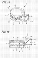
- FIG. 1A is a perspective view showing the mold according to the first embodiment
- Fig. 1B is a cross-sectional view showing the mold in Fig. 1A by cutting it along a line indicated by "A-A'”.
- a mold 1 includes a mold assembly 2, an injection aid member 3, and a sealing member 4 (see Fig. 4 ).
- the mold assembly 2 includes a first mold 21 and a second mold 22 which are opposed to each other at a certain spaced interval, and a tape member 23 which connects the outer peripheries of the two molds 21 and 22.
- the first mold 21 is formed so as to have a surface surrounded with a continuous curve such as a circle or ellipse, or surrounded with continuous curves and continuous straight lines, and has a concavely curved lens forming surface 21a.
- the second mold 22 is formed into a shape which is approximately the same as that of the first mold 21.
- the second mold 22 has a convexly curved lens forming surface 22a.
- the lens forming surface 22a of the second mold 22 is opposed to the lens forming surface 21a of the first mold 21.
- the first and second molds 21 and 22 are formed by, for example, pouring molten glass into a metal mold. It should be noted that, in this embodiment, the first and second molds according to the present invention may be formed from a resin or a metal, although the first and second molds 21 and 22 are formed from glass. Furthermore, the first mold and the second mold may be formed by using a different material from each other.
- the tape member 23 is a so-called adhesive tape, and is wound around the outer peripheries of the first and second molds 21 and 22 one or more times.
- the width of the tape member 23 is set to a width such that the tape member projects from outer peripheries of the first and second molds 21 and 22. Accordingly, the tape member 23 covers the entire outer peripheries of the first and second molds 21 and 22. It should be noted that the width of the tape member used in the present invention is sufficient, so long as a space between the first mold 21 and the second mold 22 is hermetically sealed.
- the tape member 23 includes a substrate and an adhesive layer formed on one surface (an adhesive surface) of the substrate.
- the substrate of the tape member 23 may include polyester.
- the adhesive layer for example, adhesives which do not dissolve in a plastic lens material 51 (see Fig. 4 ) or do not inhibit polymerisation are preferable, and examples thereof may include silicone adhesives, and the like.
- a cavity 24 which is surrounded by the lens forming surfaces 21a and 22a of the first and second molds 21 and 22, and the tape member 23 is formed.
- the plastic lens material 51 (see Fig. 4 ) is injected into the cavity 24.
- the tape member 23 forming the outer periphery of the cavity 24 is provided with a through hole 25.
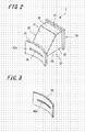
- FIG. 2 is a perspective view showing the injection aid member 3.
- the injection aid member 3 is formed by, for example, injection-molding a thermoplastic resin that can easily be processed, such as polypropylene or polyethylene.
- the injection aid member 3 includes an aid member body 31 which is formed into an approximately quadrangular-tubular shape, and an attachment 32 that is continuous with one end of the aid member body 31.
- the aid member body 31 includes a first opening 33 and a second opening 34 which is opposed to the first opening 33.
- the first opening 33 is formed into a long and narrow, approximately rectangular shape
- the second opening 34 is formed into an approximately quadrangular shape (see Fig. 2 .
- the opening area of the first opening 33 is set to be smaller than that of the second opening 34.
- the aid member body 31 includes a guide plate 35, a plane plate 36 which is opposed to the guide plate 35, a inclined plate 37 that is continuous with the plane plate 36, and two side plates 38 and 39.
- the guide plate 35 forms one side of the first opening 33 and one side of the second opening 34, and has a flat surface which is in parallel with a direction in which both of the openings 33 and 34 open.
- the flat surface of the guide plate 35 is a guide surface that guides a nozzle 101 (see Fig. 4 ).
- the plane plate 36 forms one side of the second opening 34, and has a flat surface which is in parallel with the flat surface of the guide plate 35.
- the inclined plate 37 forms one side of the first opening 33, and is inclined to a direction in which the first opening 33 and the second opening 34 open. This makes an interior space 31a in the aid member body 31 narrower as the interior space 31a approaches the first opening 33 (see Fig. 2 ) .
- Each of the two side plates 38 and 39 is continuous with the guide plate 35, the plane plate 36 and the inclined plate 37, and form two sides of the first opening 33 and two sides of the second opening 34.
- a fixing portion 41 is provided on the periphery of the second opening 34 .
- the fixing portion 41 is continuous with the guide plate 35, the plane plate 36 and the two side plates 38 and 39, and is formed into a quadrangular frame shape (see Fig. 1 ).
- the sealing member 4 is firmly attached and fixed to the fixing portion 41.
- the attachment 32 is provided on the periphery of the first opening 33, and is formed into an approximately rectangular frame shape.
- the attachment 32 is curved in a circular arc shape, and has a curved surface 32a corresponding to the outer periphery surface of the mold assembly 2. That is, the radius of curvature of the curved surface 32a of the attachment 32 is set to be approximately the same as the radius of curvature of the outer periphery surface of the mold assembly 2.
- the injection aid member 3 is attached to the mold assembly 2 by fixing the curved surface 32a of the attachment 32 to the outer periphery surface of the mold assembly 2.
- Fig. 2 is a perspective view showing the adhesive member 45.
- the adhesive member 45 is a double-sided adhesive tape used for fixing the curved surface 32a of the attachment 32 to the outer periphery surface of the mold assembly 2.
- the adhesive member 45 is formed into a rectangular sheet shape having approximately the same size as that of the attachment 32, and has a through hole 45a.
- the through hole 45a in the adhesive member 45 is opposed to the first opening 33 of the injection aid member 3.
- the adhesive member 45 has a polyethylene substrate and an adhesive layer composed of an acrylic adhesive agent. Polyesters or fabrics may be used as the substrate of the adhesive member 45. Furthermore, as the adhesive layer, adhesives which do not dissolve in the plastic lens material 51 (see Fig. 4 ) or do not inhibit polymerization are preferably used, and rubber adhesives may be used in addition to the silicone adhesives.
- the double-sided adhesive tape has been used as the adhesive member.
- cold-setting adhesives, thermosetting adhesives, ultraviolet cure adhesive, or hot-melt adhesives may be used so long as the adhesives do not dissolve in the plastic lens material 51(see Fig. 4 ) and adhesiveness is not impaired.
- the sealing member 4 (see Fig. 4 ) is formed into a sheet shape having a size covering the second opening 34 of the aid member body 31 and the fixing portion 41.
- the sealing member 4 is firmly attached and fixed to the fixing portion 41 by using a heat-sealing method or an adhesive, and the like.
- FIG. 4 Figs. 4A-4E are explanatory views illustrating the method for producing a plastic lens according to the present invention.
- a mold assembly step In the method for producing a plastic lens by using the mold 1, a mold assembly step, an aid member attachment step, a through hole forming step, an injection step, a sealing step, and a polymerization step are taken.
- the mold assembly step will be explained referring to Fig. 4A .
- the first mold 21 and the second mold 22 are caused to face each other at a certain spaced interval, and the outer peripheries thereof are connected by the tape member 23, whereby the mold assembly 2 is assembled.
- the cavity 24, which is hermetically sealed by the lens forming surfaces 21a and 22a of the first and second molds 21 and 22, and the tape member 23 is formed.
- the aid member attachment step will be explained referring to Fig. 4B .
- the injection aid member 3 is attached to the mold assembly 2. That is, the curved surface 32a of the attachment 32 provided on the injection aid member 3 is firmly attached and fixed to the outer periphery surface of the mold assembly 2 through the adhesive member 45.
- the curved surface 32a of the attachment 32 is set so as to have a radius of curvature corresponding to (approximately the same as) that of the outer periphery surface of the mold assembly 2. Accordingly, the curved surface 32a of the attachment 32 can be securely attached to the outer periphery surface of the mold assembly 2.
- the first opening 33 of the injection aid member 3 is caused to face the outer periphery of the cavity 24 formed in the mold assembly 2 through the tape member 23. Furthermore, the first opening 33 is located on the side of the lens forming surface 22a of the second mold 22. That is, when the injection aid member 3 is attached to the mold assembly 2, the first opening 33 is caused to face the outer periphery of the cavity 24, and an extended line of the first opening 33 intersects with the lens forming surface 22a of the second mold 22.
- the through hole forming step will be explained referring to Fig. 4C .
- the through hole 25 is provided in a portion of the tape member 23 opposed to the first opening 33, whereby the interior space 31a in the injection aid member 3 and the cavity 24 are connected to each other through the through hole 25 and the first opening 33.
- the through hole 25 is provided by inserting a tool from the second opening 34 of the injection aid member 3, and making a cut in the tape member 23 along the first opening 33.
- the tape member 23 may be processed by a method using laser to provide the through hole 25.
- the through hole 25 may be provided after the mold assembly step has been taken, and before the injection aid member 3 is attached.
- the injection step will be explained referring to Fig. 4D .
- the nozzle 101 is inserted from the second opening 34 of the injection aid member 3, and the plastic lens material 51 is injected into the cavity 24.
- thermosetting resin composition polymerization-curable by heat is used as the plastic lens material 51.
- the plastic lens material 51 bisisocyanatomethylbicycloheptane, 1-mercapto-2,3-bis(mercaptoethylthio)propane, and pentaerythritol-tetrakismercaptopropionate are mixed, and, as a polymerization catalyst, a monomer using dibutyltindichloride is used.
- a photocurable resin composition which is polymerization-curable by light such as ultraviolet rays can be used as the plastic lens material 51 in the present Invention, in addition to the thermosetting resin compositions described above.
- the photocurable resin composition contains photocurable monomers, and a photopolymerization initiator.
- the nozzle 101 which has been inserted from the second opening 34 is guided along the guide plate 35 of the injection aid member 3.
- the tip part 101a passes through the through hole 25, and is inserted into the cavity 24.
- the plastic lens material 51 is discharged from the nozzle 101.
- the plastic lens material 51 discharged from the nozzle 101 first moves on the lens forming surface 22a of the second mold 22, and is filled in the cavity 24. As a result, a formation of bubbles in plastic lens material 51 filled in the cavity 24 can be inhibited.
- the cavity 24 is filled with the plastic lens material 51, and the material overflows into the interior space 31a of the injection aid member 3 through the through hole 25.
- the injection of the plastic lens material 51 is continued until an appropriate amount of the plastic lens material 51 is stored in the interior space 31a of the injection aid member 3 (see Fig. 4E ).
- the nozzle 101 is pulled out from the injection aid member 3.
- the sealing step will be explained referring to Fig. 4E .
- the sealing step the second opening 34 of the injection aid member 3 is sealed with the sealing member 4.
- the sealing member 4 is firmly attached and fixed to the fixing portion 41 by using a heat-sealing method, whereby the cavity 24 and the interior space 31a in the injection aid member 3 connected to the cavity 24 are hermetically sealed.
- the sealing member 4 because the sealing member 4 is not brought into contact with the plastic lens material 51, the second opening 34 can be securely sealed without being affected by the plastic lens material 51.
- the injection of the plastic lens material 51 is stopped when an appropriate amount of the plastic lens material 51 is stored in the interior space 31a of the injection aid member 3 . Accordingly, the interior space 31a in the injection aid member 3 is not filled with the plastic lens material 51. Thus, the second opening 34 can easily be sealed with the sealing member 4, thereby improving the workability of the sealing operation.
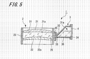
- Fig. 5 is an explanatory view showing the mold 1 in a state in which the sealing step has been taken. As shown in Fig. 5 , the mold 1 on which the sealing operation has been performed can be placed such that the guide plate 35 of the injection aid member 3 is directed downwardly.
- the appropriate amount of the plastic lens material 51 is an amount which is decided depending on the position of the mold in the polymerization step described below and in which the trough hole 25 is completely filled with the plastic lens material 51.
- the polymerization step the plastic lens material 51, which has been injected in the cavity 24, is polymerized.
- the polymerization is performed by placing the mold 1 that has been filled with the plastic lens material 51 in a heating furnace (not shown), whereby the plastic lens material 51 is cured to thereby form a plastic lens (not shown).
- the temperature inside the heating furnace was raised to 120°C in about 20 hours, however the sealing property of the interior space 31a of the injection aid member 3 and the cavity 24, sealed with the sealing member 4, was not impaired.
- the polymerization is performed by irradiating the material with light such as ultraviolet rays or visible rays using a light irradiation apparatus.
- the cured plastic lens material 51 is released from the mold and the plastic lens is taken out from the mold.
- the plastic lens taken out is, for example, a finished lens or semi-finished lens.
- Both optical surfaces of the finished lens are completely processed at the time the lens was molded.
- the semi-finished lens one optical surface is completely processed at the time the lens was molded, and the other surface is processed to have a dioptric power which is required by customers.
- the semi-finished lens can be employed as a special lens such as a progressive-power lens or a prism prescription lens.
- the plastic lens material 51 with which the cavity 24 is filled and which overflows from the through hole 25 can be stored in the interior space 31a of the injection aid member 3. Accordingly, it is not necessary to precisely control the liquid level of the plastic lens material to be injected to the cavity. Moreover, in the injection step of the plastic lens material 51, the leakage of the plastic lens material 51 outside the mold 1 is prevented. This solves problems such as the plastic lens material 51 adheres to instruments or workers involved in the injection step or the polymerization step.
- the second opening 34 of the injection aid member 3 is sealed with the sealing member 4.
- the plastic lens material 51 discharged from the nozzle 101 moves on the lens forming surface 22a of the second mold 22, and filled in the cavity 24. This can inhibit a formation of bubbles in the plastic lens material 51 filled in the cavity 24.
- the curved surface 32a of the attachment 32 provided on the injection aid member 3 is arranged to have a radius of curvature approximately the same as that of the outer periphery surface of the mold assembly 2.
- the curved surface 32a of the attachment 32 can firmly be attached to the outer periphery surface of the mold assembly 2.
- the interior space 31a in the injection aid member 3 and the cavity 24 are securely hermetically sealed.
- the second opening 34 is larder than the first opening 33. Therefore, the nozzle 101 can be easily inserted into the injection aid member 3. Furthermore, because the first opening 33 is formed into a long and arrow, approximately rectangular shape, even if a plastic lens having a thin outer periphery is formed, the first opening 33 can be caused to face the outer periphery of the cavity. Moreover, because the second opening 34 can be formed larder with respect to the nozzle 101, it is not necessary to control the positions of the nozzle 101 and the mold 1 with very high precision when inserting the nozzle 101. Thus, the nozzle 101 can be easily inserted into the injection aid member 3.
- the interior space 31a in the injection aid member 3 becomes narrower as the interior space 31a approaches the first opening 33.
- the guide plate 35 forms one side of the first opening 33 and one side of the second opening 34, and has a flat surface which is in parallel with a direction in which both openings 33 and 34 open.
- the inclined plate 37 forms one side of the first opening 33 and is inclined to a direction in which the first opening 33 and the second opening 34 open.
- the gas (air) in the interior space 31a does not enter the cavity 24.
- the tip part 101a of the nozzle 101 can easily be inserted into the cavity 24 by inserting the nozzle 101 along the flat surface of the guide plate 35.
- the radius of curvature of the curved surface 32a of the attachment 32 is set to be approximately the same as the radius of curvature of the outer periphery surface of the mold assembly 2.
- the attachment used in the present invention maybe configured to be elastically deformable in a direction in which the radius of curvature of the curved surface is changed.
- on mold may be prepared for multiple mold assemblies having a radius of curvature of the outer periphery surface different from each another, thereby fostering the versatility of the mold.
- the second opening 34 of the injection aid member 3 is sealed with the sealing member 4.
- the second opening of the injection aid member in the present invention may be sealed by welding the injection aid member itself using ultrasonic waves, or the like. In such a case, the injection aid member also serves as the sealing member.
- the second opening is arranged to have two independent tubular holes. Of the two tubular holes, one hole is used for inserting the nozzle, and the other hole is used for exhausting the air in the interior space 31a. This can make the opening area of the second opening smaller, and the welding can easily be performed.
- Fig. 6A is a perspective view showing a mold of the second embodiment
- Fig. 6B is the cross-sectional view showing the mold in Fig. 6A by cutting it along a line indicated by "B-B'".
- a mold 61 according to the second embodiment has the same structure as that of the mold 1 of the first embodiment (see Fig. 1 ), except for a mold assembly 62. Accordingly, with respect to the mold 61, the mold assembly 62 alone will be explained and the same reference numerals are used to designate members identical to those of the mold 1, and a description of the identical members will be omitted.
- the mold assembly 62 includes the first mold 21 and the second mold 22 which are opposed to each other at a certain spaced interval, and a tape member 63 which connects outer peripheries of the two molds 21 and 22. Since the two molds 21 and 22 have the same shape and material as in the mold 1 (see Fig. 1 ), the description thereof is omitted.
- the tape member 63 is an adhesive tape which is the same as the tape member 23, and is wound around the outer peripheries of the first and second molds 21 and 22.
- the length (in a longitudinal direction) of the tape member 63 is arranged to be shorter than that of the outer peripheries of the first mold 21 and the second mold 22.
- a cavity 64 and an opening for injection 65 which opens the cavity 64 are formed in the mold assembly 62.
- the opening for injection 65 of the mold assembly 62 is arranged to be smaller than the curved surface 32a of the attachment 32 provided on the injection aid member 3.
- the injection aid member 3 is attached to the periphery of the opening for injection 65 formed on the mold assembly 62. Then, the attachment 32 of the injection aid member 3 is fixed to the outer periphery surfaces of the first and second molds 21 and 22 with the adhesive member 45. When the injection aid member 3 is attached to the mold assembly 62, the opening for injection 65 is covered by the attachment 32 of the injection aid ember 3. Then, the cavity 64 in the mold assembly 62 and the interior space 31a in the injection aid member 3 are connected to each other through the first opening 33.
- a method for producing a plastic lens using the mold 61 will be explained.
- a mold assembly step, an aid member attachment step, an injection step, a sealing step, and a polymerization step are taken.
- the through hole forming step taken in the method for producing a plastic lens using the mold 1 is omitted.
- the first mold 21 and the second mold 22 are caused to face each other at a certain spaced interval, and the outer peripheries thereof are connected by the tape member 63, whereby the mold assembly 62 having the cavity 64 provided with the opening for injection 65 is assembled.
- the opening for injection may be provided after the cavity is hermetically sealed with a tape member longer than the outer periphery of the first mold 21 or second mold 22, and then a cut is made in the tape member. Furthermore, the first mold 21 and the second molds 22 may be connected to each other by using a tape member in which the opening for injection has previously been provided.
- the injection aid member 3 is attached to the mold assembly 62.
- the opening for injection 65 is covered with the attachment 32, and the cavity 64 and the interior space 31a in the injection aid member 3 are connected to each other.
- the same effects as those obtained by employing the method for producing a plastic lens and the mold 1 according to the first embodiment can also be obtained.
- the through hole forming step can be omitted, the work efficiency can be improved.
- the opening for injection 65 is formed on the mold assembly 62 by making the length of the tape member 63 shorter than that of the outer periphery of the first mold 21 or second mold 22.
- an opening for injection in the present invention may be previously formed in the tape member. In such a case, the length of the tape member is set to be longer than that of the outer periphery of the first mold 21 or the second mold 22.
- Fig. 7 is the cross-sectional view showing the injection aid member of the mold according to the third embodiment.
- the mold according to the third embodiment has the same structure as that of the mold 1 of the first embodiment (see Fig. 1 ), except for an injection aid member 73.
- an injection aid member 73 alone will be described.
- the injection aid member 73 is formed by injection-molding a thermoplastic resin like the injection aid member 3 of the first embodiment, and includes an aid member body 81 which is formed into an approximately quadrangular-tubular shape and the attachment 32 which is continuous with one end of the aid member body 81.
- the attachment 32 is identical to the attachment 32 of the injection aid member 3 in the first embodiment.
- the aid member body 81 includes a first opening 83 which is formed into a long and narrow, approximately rectangular shape, and a second opening 84 which is formed into an approximately quadrangular shape.
- the opening area of the first opening 83 is set to be smaller than the opening area of the second opening 84.
- the aid member body 81 has a guide plate 85, a plane plate 86 opposed to the guide plate 85, an inclined plate 87 that is continuous with the plane plate 86, and two side plates 88.
- the guide plate 85 forms one side of the first opening 83 and one side of the second opening 84.
- the inner surface of the guide plate 85 has a taper guide surface 85a on the side of the first opening 83, an inclined surface 85b on the side of the second opening 84, and a flat surface 85c formed between the taper guide, surface 85a and the inclined surface 85b.
- the taper guide surface 85a is a curved surface which makes an interior space 81a of the aid member body 81 continuously smaller as the taper guide surface 85a approaches a first opening 83, and has an approximately arc-shaped cross-section.
- the taper guide surface 85a is a guide surface guiding the nozzle 101 (see Fig. 4 ) to the first opening 83.
- the inclined surface 85b is inclined to a direction separating from the plane plate 86, and makes the interior space 81a of the aid member body 81 continuously larger as the inclined surface 85b approaches a second opening 84.
- the flat surface 85c is in parallel with a direction in which both openings 83 and 84 open.
- the plane plate 86 forms one side of the second opening 84 and has an inner surface in parallel with the flat surface 85c of the guide plate 85.
- the inclined plate 87 forms on side of the first opening 83, and is inclined to a direction in which both of the openings 83 and 84 open. With this structure, the interior space 81a in the aid member body 81 becomes narrower as the interior space 81a approaches the first opening 83.
- the inclined plate 87 has a taper guide surface 87a which makes the interior space 81a in the aid member body 81 continuously smaller as the inclined plate 87 approaches the first opening 83.
- the taper guide surface 87a serves as a guide surface guiding the nozzle 101 to the first opening 83.
- Each of the two side plates 88 is continuous with the guide plate 85, the plane plate 86 and the inclined plate 87, and forms two sides of the first opening 83 and two sides of the second opening 84. Furthermore the fixing portion 41 is provided on the periphery of the second opening 84. The fixing portion 41 is formed into a quadrangular frame shape that is continuous with the guide plate 85, the plane pate 86 and the two side plates 88. The sealing member 4 is firmly attached and fixed to the fixing portion 41 (see Fig. 5 ).
- the interior space 81a of the injection aid member 73 has an asymmetrical shape in a direction in which the guide plate 85 and the plane plate 86 are opposed to each other along an axis of the first opening 83, and thus the same effects as those obtained with the mold 1 in the first embodiment can be obtained. Furthermore, since the taper guide surface 85a and the inclined surface 85b are provided on the aid member body 81, even if the nozzle 101 has a shape in which its root portion is wide and a tip portion becomes gradually narrower like a tip portion of a cylinder is crushed in order to secure, for example, the rigidity of the nozzle 101, the nozzle 101 can perpendicularly be inserted. As a result, the detachment of the aid member body 81 from the mold assembly 2, which is caused by a pressure applied to the first opening 83 and the attachment 32 when the nozzle is obliquely inserted into the first opening 83 can be prevented.
- the present invention is not limited to the embodiments which have been described and shown in drawings, and various modifications can be made within the scope of the applended claims.
- the lens forming surface 21a of the first mold 21 is arranged to have a concave surface
- the lens forming surface 22a of the second mold 22 is arranged to have a convex surface.
- the type of the surface of the lens forming surface according to the present invention can suitably be decided depending on the shape of a plastic lens to be formed.
Landscapes
- Engineering & Computer Science (AREA)
- Health & Medical Sciences (AREA)
- Manufacturing & Machinery (AREA)
- Ophthalmology & Optometry (AREA)
- Mechanical Engineering (AREA)
- Casting Or Compression Moulding Of Plastics Or The Like (AREA)
- Moulds For Moulding Plastics Or The Like (AREA)
Abstract

Description
- The present invention relates to a mold for molding a plastic lens by cast polymerization, and a method for producing a plastic lens using the mold.
- Plastic lenses have advantages that they are lighter and are less easily broken than glass lenses. For that reason, the plastic lenses have been used as various lenses including spectacle lenses. The plastic lenses for spectacles are generally formed by cast polymerization.
- The cast polymerization is a method in which a liquid curable plastic raw material is injected into a mold and is cured by heat or energy such as ultraviolet rays to thereby obtain a molded article. A mold used in the cast polymerization is formed, for example, by causing a pair of molds to face each other at a certain spaced interval, and winding an adhesive tape around the entire peripheries of these molds.
- A technique for producing a plastic lens using such a mold is disclosed, for example, in Patent Document 1. Patent Document 1 describes a liquid plastic raw material injection apparatus for forming a plastic lens . The liquid plastic raw material injection apparatus disclosed in Patent Document 1 includes an injection pipe for injecting liquid plastic raw material into a mold, and a suction pipe provided next to this injection pipe.
- When the liquid plastic raw material is infected into the mold, a portion of an adhesive tape bonding the pair of molds is peeled off to make an opening, and the injection pipe is inserted into the mold. Under this condition, the tip of the suction pipe is located at the same level as that of the liquid when the mold is filled with the liquid plastic raw material. When the liquid plastic raw material is injected into the mold, the liquid surface reaches the tip of the suction pipe and blocks a suction port, thereby changing a negative pressure in the suction pipe.
- When the liquid plastic raw material infection apparatus detects the change of the negative pressure in the suction pipe, it stops the injection of the liquid plastic raw material. Then, the adhesive tape is applied again, and a space (cavity) in the mold is sealed.
- Furthermore,
Patent Document 2 discloses a technique concerning a production method of a cured plastic product. According to the production method of a cured plastic product disclosed inPatent Document 2, an injection hole is provided in an adhesive tape wound around the entire periphery of a mold, and a liquid plastic raw material is injected through the injection hole. After the liquid plastic raw material is filled in the mold, an ultraviolet curable resin is applied to the injection hole to seal a space in the mold. -
- [Patent Document 1] Japanese Patent Laid-Open Publication No.
2-169208 - [Patent Document 2] Japanese Patnet Laid-Open Publication No.
6-155481 - It has been difficult to precisely control the liquid level of the liquid plastic raw material with the liquid plastic raw material injection apparatus disclosed in Patent Document 1. For example, the volumetric capacity of the mold and thickness of the outer periphery wall of the mold vary depending on the shape of a plastic lens to be produced. Therefore, if the time from when the change of the negative pressure in the suction pipe is detected to when the injection of the liquid plastic raw-material is stopped is always the same, the liquid plastic raw material may not be filled sufficiently, or the liquid plastic raw material may overflow from the mold.
- When the liquid plastic raw material is not filled sufficiently, a bubble defect in which air in the mold penetrates into a plastic lens as bubbles during polymerization may be produced. On the other hand, when the liquid plastic raw material overflows from the mold, the liquid plastic raw material adheres to a part around an opening, and thus the defective adhesion of the adhesive tape may easily occur when the adhesive tape is wound again. If the defective adhesion occurs, air penetrates from the outside during the polymerization, which may result in the production of the bubble defect in the plastic lens.
- Meanwhile, in order to precisely control the liquid level of the liquid plastic raw material, the liquid plastic raw material may be slowly injected, in other words, the flow rate of the liquid plastic raw material to be injected may be decreased. The decrease in the flow rate of the liquid plastic raw material, however, may result in the decrease in the productivity.
- Furthermore, in the production method of the cured plastic product disclosed in
Patent Document 2, the productivity has not easily been increased. The injection hole provided in the adhesive tape is required to be set to be larger than the nozzle, because it also serves as an exhaust port for air in the mold. The larger the cross-sectional area of the nozzle hole is , the greater the flow rate of the liquid plastic raw material can be, and the liquid plastic raw material can be filled faster. When the cross-sectional area of the nozzle hole and the injection hole are made large, however, a large period of time is required for sealing the injection hole. - In addition, according to the production method of the cured plastic product disclosed in
Patent Document 2, the liquid plastic raw material may sometimes overflow from the injection hole. It may cause concern that the overflowed liquid plastic raw material may adversely affect instruments or workers involved in an infection operation or a polymerization step. - The present invention has been made in view of the above-discussed problem, and aims to eliminate the need for precisely controlling the liquid level of the liquid plastic raw material (plastic material), and improve the productivity by increasing the flow rate of the liquid plastic raw material.
- In order to solve the problems described above, and achieve objectives of the present invention, the mold according to the present invention includes a mold assembly and an injection aid member which is attached to the mold assembly. The mold assembly includes a first mold and a second mold which are opposed to each other, a tape member which connects the outer peripheries of the first mold and the second mold, a cavity to which a plastic lens material is injected, and a through hole which opens a portion of the cavity. The injection aid member includes a first opening which is opposed to the through hole of the mold assembly, a second opening which is connected to the first opening, and an attachment provided around the first opening and firmly attached to the mold assembly.
- The method for producing a plastic lens according to the present invention includes a mold assembly step, an aid member attachment step, a through hole forming step, an injection step, a sealing step, and a polymerization step. In the mold assembly step, a first mold and a second mold are caused to face each other, and outer peripheries of the first mold and the second mold are connected by a tape member to assemble a mold assembly having a cavity. In the aid member attachment step, an attachment provided around a first opening of an injection aid member having the first opening and a second opening connected to the first opening is firmly attached to the mold assembly, and the first opening is caused to face the tape member forming an outer periphery of the cavity.
- In the through hole forming step, a through hole is provided in a portion of the tape member opposed to the first opening. In the injection step, a nozzle is inserted through the second opening of the injection aid member into the cavity, and a plastic lens material is injected thereto. In the sealing step, the second opening of the injection aid member is sealed with a sealing member. In the polymerization step, the plastic lens material injected to the cavity is polymerized.
- According to the present invention, the nozzle is inserted into the injection aid member, and the plastic lens material is injected into the cavity. Thus, the plastic lens material which has filled the cavity and has overflowed from the through hole can be stored in the injection aid member. Hence, the leakage of the plastic lens material to the outside can be prevented. This solves problems such as the plastic lens material adheres to instruments or workers involved in the injection step or in the polymerization step.
- Furthermore, according to the present invention, the second opening of the injection aid member is sealed with the sealing member to thereby hermetically seal the cavity. This eliminates the need for precisely controlling the liquid level of the plastic lens material to be injected to the cavity. Furthermore, even if the crass-sectional area of the nozzle and the through hole are made large, the cavity can easily be hermetically sealed by sealing the injection aid member.
- According to the present invention, the precise control of the liquid level of the plastic lens material is not required, and the productivity can be improved by increasing the flow rate of the plastic lens material.
-
-
Fig. 1A is a perspective view showing a mold according to a first embodiment of the present invention, andFig. 1B is a cross-sectional view showing the mold inFig. 1A by cutting it along with a line indicated by "A-A'". -
Fig. 2 is a perspective view showing an injection aid member to be used with the mold according to the first embodiment of the present invention. -
Fig. 3 is a perspective view showing an adhesive member to be used with the mold according to the first embodiment of the present invention. -
Figs. 4A-4E are explanatory views illustrating a method for producing a plastic lens of the present invention. -
Fig. 5 is an explanatory view illustrating a state in which a plastic lens material is injected into the mold of the invention, and a through hole is horizontally directed. -
Fig. 6A is a perspective view showing a mold according to a second embodiment of the present invention, andFig. 6B is a cross-sectional view showing the mold inFig. 6A by cutting it along with a line indicated by "B-B'". -
Fig. 7 is a cross-sectional view showing an injection aid member to be used with a mold according to a third embodiment of the present invention. - Embodiments for carrying out a method for producing a plastic lens and mold according to the present invention will be explained below, referring to
Fig. 1 to Fig. 7 . In each drawing, the same reference numerals are used to designate identical members. - First, a mold according to the first embodiment of the mold of the present invention will be explained referring to
Fig. 1 . -
Fig. 1A is a perspective view showing the mold according to the first embodiment, andFig. 1B is a cross-sectional view showing the mold inFig. 1A by cutting it along a line indicated by "A-A'".
A mold 1 includes amold assembly 2, aninjection aid member 3, and a sealing member 4 (seeFig. 4 ). - The
mold assembly 2 includes afirst mold 21 and asecond mold 22 which are opposed to each other at a certain spaced interval, and atape member 23 which connects the outer peripheries of the twomolds - The
first mold 21 is formed so as to have a surface surrounded with a continuous curve such as a circle or ellipse, or surrounded with continuous curves and continuous straight lines, and has a concavely curvedlens forming surface 21a. Thesecond mold 22 is formed into a shape which is approximately the same as that of thefirst mold 21. Thesecond mold 22 has a convexly curvedlens forming surface 22a. Thelens forming surface 22a of thesecond mold 22 is opposed to thelens forming surface 21a of thefirst mold 21. - The first and
second molds second molds - The
tape member 23 is a so-called adhesive tape, and is wound around the outer peripheries of the first andsecond molds tape member 23 is set to a width such that the tape member projects from outer peripheries of the first andsecond molds tape member 23 covers the entire outer peripheries of the first andsecond molds first mold 21 and thesecond mold 22 is hermetically sealed. - The
tape member 23 includes a substrate and an adhesive layer formed on one surface (an adhesive surface) of the substrate. Examples of the substrate of thetape member 23 may include polyester. On the other hand, as the adhesive layer, for example, adhesives which do not dissolve in a plastic lens material 51 (seeFig. 4 ) or do not inhibit polymerisation are preferable, and examples thereof may include silicone adhesives, and the like. - In the
mold assembly 2, acavity 24 which is surrounded by thelens forming surfaces second molds tape member 23 is formed. The plastic lens material 51 (seeFig. 4 ) is injected into thecavity 24. It should be noted that thetape member 23 forming the outer periphery of thecavity 24 is provided with a throughhole 25. - Next, the
infection aid member 3 will be explained referring toFig. 2 .
Fig. 2 is a perspective view showing theinjection aid member 3. - The
injection aid member 3 is formed by, for example, injection-molding a thermoplastic resin that can easily be processed, such as polypropylene or polyethylene. Theinjection aid member 3 includes anaid member body 31 which is formed into an approximately quadrangular-tubular shape, and anattachment 32 that is continuous with one end of theaid member body 31. - The
aid member body 31 includes afirst opening 33 and asecond opening 34 which is opposed to thefirst opening 33. Thefirst opening 33 is formed into a long and narrow, approximately rectangular shape, and thesecond opening 34 is formed into an approximately quadrangular shape (seeFig. 2 . The opening area of thefirst opening 33 is set to be smaller than that of thesecond opening 34. - The
aid member body 31 includes aguide plate 35, aplane plate 36 which is opposed to theguide plate 35, ainclined plate 37 that is continuous with theplane plate 36, and twoside plates guide plate 35 forms one side of thefirst opening 33 and one side of thesecond opening 34, and has a flat surface which is in parallel with a direction in which both of theopenings guide plate 35 is a guide surface that guides a nozzle 101 (seeFig. 4 ). - The
plane plate 36 forms one side of thesecond opening 34, and has a flat surface which is in parallel with the flat surface of theguide plate 35. Theinclined plate 37 forms one side of thefirst opening 33, and is inclined to a direction in which thefirst opening 33 and thesecond opening 34 open. This makes aninterior space 31a in theaid member body 31 narrower as theinterior space 31a approaches the first opening 33 (seeFig. 2 ) . Each of the twoside plates guide plate 35, theplane plate 36 and theinclined plate 37, and form two sides of thefirst opening 33 and two sides of thesecond opening 34. - A fixing
portion 41 is provided on the periphery of thesecond opening 34 . The fixingportion 41 is continuous with theguide plate 35, theplane plate 36 and the twoside plates Fig. 1 ). The sealingmember 4 is firmly attached and fixed to the fixingportion 41. - The
attachment 32 is provided on the periphery of thefirst opening 33, and is formed into an approximately rectangular frame shape. Theattachment 32 is curved in a circular arc shape, and has acurved surface 32a corresponding to the outer periphery surface of themold assembly 2. That is, the radius of curvature of thecurved surface 32a of theattachment 32 is set to be approximately the same as the radius of curvature of the outer periphery surface of themold assembly 2. Theinjection aid member 3 is attached to themold assembly 2 by fixing thecurved surface 32a of theattachment 32 to the outer periphery surface of themold assembly 2. - Next, an
adhesive member 45 will be explained referring toFig. 2 .
Fig. 2 is a perspective view showing theadhesive member 45. - The
adhesive member 45 is a double-sided adhesive tape used for fixing thecurved surface 32a of theattachment 32 to the outer periphery surface of themold assembly 2. Theadhesive member 45 is formed into a rectangular sheet shape having approximately the same size as that of theattachment 32, and has a throughhole 45a. The throughhole 45a in theadhesive member 45 is opposed to thefirst opening 33 of theinjection aid member 3. - The
adhesive member 45 has a polyethylene substrate and an adhesive layer composed of an acrylic adhesive agent. Polyesters or fabrics may be used as the substrate of theadhesive member 45. Furthermore, as the adhesive layer, adhesives which do not dissolve in the plastic lens material 51 (seeFig. 4 ) or do not inhibit polymerization are preferably used, and rubber adhesives may be used in addition to the silicone adhesives. - In this embodiment, the double-sided adhesive tape has been used as the adhesive member. However, cold-setting adhesives, thermosetting adhesives, ultraviolet cure adhesive, or hot-melt adhesives may be used so long as the adhesives do not dissolve in the plastic lens material 51(see
Fig. 4 ) and adhesiveness is not impaired. - Next, the sealing
member 4 will be explained.
The sealing member 4 (seeFig. 4 ) is formed into a sheet shape having a size covering thesecond opening 34 of theaid member body 31 and the fixingportion 41. The sealingmember 4 is firmly attached and fixed to the fixingportion 41 by using a heat-sealing method or an adhesive, and the like. - Next, a method for producing a plastic lens using the mold 1 according to the present invention is explained referring to
Fig. 4 ,
Figs. 4A-4E are explanatory views illustrating the method for producing a plastic lens according to the present invention. - In the method for producing a plastic lens by using the mold 1, a mold assembly step, an aid member attachment step, a through hole forming step, an injection step, a sealing step, and a polymerization step are taken.
- First, the mold assembly step will be explained referring to
Fig. 4A .
In the mold assembly step, thefirst mold 21 and thesecond mold 22 are caused to face each other at a certain spaced interval, and the outer peripheries thereof are connected by thetape member 23, whereby themold assembly 2 is assembled. In themold assembly 2, thecavity 24, which is hermetically sealed by thelens forming surfaces second molds tape member 23 is formed. - Next, the aid member attachment step will be explained referring to
Fig. 4B .
In the aid member attachment step, theinjection aid member 3 is attached to themold assembly 2. That is, thecurved surface 32a of theattachment 32 provided on theinjection aid member 3 is firmly attached and fixed to the outer periphery surface of themold assembly 2 through theadhesive member 45. - The
curved surface 32a of theattachment 32 is set so as to have a radius of curvature corresponding to (approximately the same as) that of the outer periphery surface of themold assembly 2. Accordingly, thecurved surface 32a of theattachment 32 can be securely attached to the outer periphery surface of themold assembly 2. - When the
injection aid member 3 is attached to themold assembly 2, thefirst opening 33 of theinjection aid member 3 is caused to face the outer periphery of thecavity 24 formed in themold assembly 2 through thetape member 23. Furthermore, thefirst opening 33 is located on the side of thelens forming surface 22a of thesecond mold 22. That is, when theinjection aid member 3 is attached to themold assembly 2, thefirst opening 33 is caused to face the outer periphery of thecavity 24, and an extended line of thefirst opening 33 intersects with thelens forming surface 22a of thesecond mold 22. - Next, the through hole forming step will be explained referring to
Fig. 4C .
In the through hole forming step, the throughhole 25 is provided in a portion of thetape member 23 opposed to thefirst opening 33, whereby theinterior space 31a in theinjection aid member 3 and thecavity 24 are connected to each other through the throughhole 25 and thefirst opening 33. - In this embodiment, the through
hole 25 is provided by inserting a tool from thesecond opening 34 of theinjection aid member 3, and making a cut in thetape member 23 along thefirst opening 33. It should be noted that, in the through hole forming step in the present invention, thetape member 23 may be processed by a method using laser to provide the throughhole 25. Furthermore, there is no restriction as to the order of the through hole forming step, and the throughhole 25 may be provided after the mold assembly step has been taken, and before theinjection aid member 3 is attached. - Next, the injection step will be explained referring to
Fig. 4D .
In the injection step, thenozzle 101 is inserted from thesecond opening 34 of theinjection aid member 3, and theplastic lens material 51 is injected into thecavity 24. - Here, the
plastic lens material 51 will be explained. In this embodiment, a thermosetting resin composition polymerization-curable by heat is used as theplastic lens material 51. Specifically, as theplastic lens material 51, bisisocyanatomethylbicycloheptane, 1-mercapto-2,3-bis(mercaptoethylthio)propane, and pentaerythritol-tetrakismercaptopropionate are mixed, and, as a polymerization catalyst, a monomer using dibutyltindichloride is used. - A photocurable resin composition which is polymerization-curable by light such as ultraviolet rays can be used as the
plastic lens material 51 in the present Invention, in addition to the thermosetting resin compositions described above. The photocurable resin composition contains photocurable monomers, and a photopolymerization initiator. - The
nozzle 101 which has been inserted from thesecond opening 34 is guided along theguide plate 35 of theinjection aid member 3. Thetip part 101a passes through the throughhole 25, and is inserted into thecavity 24. Then, theplastic lens material 51 is discharged from thenozzle 101. Theplastic lens material 51 discharged from thenozzle 101 first moves on thelens forming surface 22a of thesecond mold 22, and is filled in thecavity 24. As a result, a formation of bubbles inplastic lens material 51 filled in thecavity 24 can be inhibited. - When the injection of the
plastic lens material 51 is continuously performed, thecavity 24 is filled with theplastic lens material 51, and the material overflows into theinterior space 31a of theinjection aid member 3 through the throughhole 25. The injection of theplastic lens material 51 is continued until an appropriate amount of theplastic lens material 51 is stored in theinterior space 31a of the injection aid member 3 (seeFig. 4E ). When the injection of theplastic lens material 51 is completed, thenozzle 101 is pulled out from theinjection aid member 3. - Next, the sealing step will be explained referring to
Fig. 4E .
In the sealing step, thesecond opening 34 of theinjection aid member 3 is sealed with the sealingmember 4. - In this embodiment, the sealing
member 4 is firmly attached and fixed to the fixingportion 41 by using a heat-sealing method, whereby thecavity 24 and theinterior space 31a in theinjection aid member 3 connected to thecavity 24 are hermetically sealed. In this sealing step, because the sealingmember 4 is not brought into contact with theplastic lens material 51, thesecond opening 34 can be securely sealed without being affected by theplastic lens material 51. - As described abode, the injection of the
plastic lens material 51 is stopped when an appropriate amount of theplastic lens material 51 is stored in theinterior space 31a of theinjection aid member 3 . Accordingly, theinterior space 31a in theinjection aid member 3 is not filled with theplastic lens material 51. Thus, thesecond opening 34 can easily be sealed with the sealingmember 4, thereby improving the workability of the sealing operation. -
Fig. 5 is an explanatory view showing the mold 1 in a state in which the sealing step has been taken.
As shown inFig. 5 , the mold 1 on which the sealing operation has been performed can be placed such that theguide plate 35 of theinjection aid member 3 is directed downwardly. - Hence, if the
plastic lens material 51 is injected into theinterior space 31a of theinjection aid member 3 to such an extent that the throughhole 25 is completely filled with the material, gas (air) in theinterior space 3 lea does not enter thecavity 24. That is, the appropriate amount of theplastic lens material 51, as described above, is an amount which is decided depending on the position of the mold in the polymerization step described below and in which thetrough hole 25 is completely filled with theplastic lens material 51. - Next, the polymerization step will be explained.
In the polymerization step, theplastic lens material 51, which has been injected in thecavity 24, is polymerized. - In this embodiment, the polymerization is performed by placing the mold 1 that has been filled with the
plastic lens material 51 in a heating furnace (not shown), whereby theplastic lens material 51 is cured to thereby form a plastic lens (not shown). In this embodiment, the temperature inside the heating furnace was raised to 120°C in about 20 hours, however the sealing property of theinterior space 31a of theinjection aid member 3 and thecavity 24, sealed with the sealingmember 4, was not impaired. - When a photocurable resin composition is used as the plastic lens material, the polymerization is performed by irradiating the material with light such as ultraviolet rays or visible rays using a light irradiation apparatus.
- After the polymerization step is taken, the cured
plastic lens material 51 is released from the mold and the plastic lens is taken out from the mold. The plastic lens taken out is, for example, a finished lens or semi-finished lens. - Both optical surfaces of the finished lens are completely processed at the time the lens was molded. On the other hand, as to the semi-finished lens, one optical surface is completely processed at the time the lens was molded, and the other surface is processed to have a dioptric power which is required by customers. The semi-finished lens can be employed as a special lens such as a progressive-power lens or a prism prescription lens.
- According to the method for producing a plastic lens and the mold 1 in this embodiment, the
plastic lens material 51 with which thecavity 24 is filled and which overflows from the throughhole 25 can be stored in theinterior space 31a of theinjection aid member 3. Accordingly, it is not necessary to precisely control the liquid level of the plastic lens material to be injected to the cavity. Moreover, in the injection step of theplastic lens material 51, the leakage of theplastic lens material 51 outside the mold 1 is prevented. This solves problems such as theplastic lens material 51 adheres to instruments or workers involved in the injection step or the polymerization step. - According to the method for producing a plastic lens and the mold 1 in this embodiment, the
second opening 34 of theinjection aid member 3 is sealed with the sealingmember 4. Thus, even if the cross-sectional area of the hole of thenozzle 101 and the throughhole 25 are made large, the operation for sealing theinjection aid member 3 does not become complicated, and thecavity 24 can easily be hermetically sealed. Hence, the flow rate of the plastic material can be increased to thereby improve the productivity. - According to the method for producing a plastic lens and the mold 1 in this embodiment, the
plastic lens material 51 discharged from thenozzle 101 moves on thelens forming surface 22a of thesecond mold 22, and filled in thecavity 24. This can inhibit a formation of bubbles in theplastic lens material 51 filled in thecavity 24. - According to the mold 1 in this embodiment, the
curved surface 32a of theattachment 32 provided on theinjection aid member 3 is arranged to have a radius of curvature approximately the same as that of the outer periphery surface of themold assembly 2. With this arrangement, thecurved surface 32a of theattachment 32 can firmly be attached to the outer periphery surface of themold assembly 2. As a result, theinterior space 31a in theinjection aid member 3 and thecavity 24 are securely hermetically sealed. - According to the mold 1 in this embodiment, the
second opening 34 is larder than thefirst opening 33. Therefore, thenozzle 101 can be easily inserted into theinjection aid member 3. Furthermore, because thefirst opening 33 is formed into a long and arrow, approximately rectangular shape, even if a plastic lens having a thin outer periphery is formed, thefirst opening 33 can be caused to face the outer periphery of the cavity. Moreover, because thesecond opening 34 can be formed larder with respect to thenozzle 101, it is not necessary to control the positions of thenozzle 101 and the mold 1 with very high precision when inserting thenozzle 101. Thus, thenozzle 101 can be easily inserted into theinjection aid member 3. - According to the mold 1 in this embodiment, the
interior space 31a in theinjection aid member 3 becomes narrower as theinterior space 31a approaches thefirst opening 33. In addiction, theguide plate 35 forms one side of thefirst opening 33 and one side of thesecond opening 34, and has a flat surface which is in parallel with a direction in which bothopenings inclined plate 37 forms one side of thefirst opening 33 and is inclined to a direction in which thefirst opening 33 and thesecond opening 34 open. - Thus, even when the
guide plate 35 of theinjection aid member 3 is placed downwardly, the gas (air) in theinterior space 31a does not enter thecavity 24. Moreover, thetip part 101a of thenozzle 101 can easily be inserted into thecavity 24 by inserting thenozzle 101 along the flat surface of theguide plate 35. - In the mold 1 in this embodiment, the radius of curvature of the
curved surface 32a of theattachment 32 is set to be approximately the same as the radius of curvature of the outer periphery surface of themold assembly 2. The attachment used in the present invention, however, maybe configured to be elastically deformable in a direction in which the radius of curvature of the curved surface is changed. When the attachment is made in this manner, on mold may be prepared for multiple mold assemblies having a radius of curvature of the outer periphery surface different from each another, thereby fostering the versatility of the mold. - Furthermore, according to the mold 1 in this embodiment, the
second opening 34 of theinjection aid member 3 is sealed with the sealingmember 4. The second opening of the injection aid member in the present invention, however, may be sealed by welding the injection aid member itself using ultrasonic waves, or the like. In such a case, the injection aid member also serves as the sealing member. - When the injection aid member itself is welded using ultrasonic waves to seal the second opining, it is preferable that the second opening is arranged to have two independent tubular holes. Of the two tubular holes, one hole is used for inserting the nozzle, and the other hole is used for exhausting the air in the
interior space 31a. This can make the opening area of the second opening smaller, and the welding can easily be performed. - Next, a mold according to the second embodiment of the present invention will be explained referring to
Figs. 6A-6B .
Fig. 6A is a perspective view showing a mold of the second embodiment, andFig. 6B is the cross-sectional view showing the mold inFig. 6A by cutting it along a line indicated by "B-B'". - A
mold 61 according to the second embodiment has the same structure as that of the mold 1 of the first embodiment (seeFig. 1 ), except for amold assembly 62. Accordingly, with respect to themold 61, themold assembly 62 alone will be explained and the same reference numerals are used to designate members identical to those of the mold 1, and a description of the identical members will be omitted. - The
mold assembly 62 includes thefirst mold 21 and thesecond mold 22 which are opposed to each other at a certain spaced interval, and atape member 63 which connects outer peripheries of the twomolds molds Fig. 1 ), the description thereof is omitted. - The
tape member 63 is an adhesive tape which is the same as thetape member 23, and is wound around the outer peripheries of the first andsecond molds tape member 63 is arranged to be shorter than that of the outer peripheries of thefirst mold 21 and thesecond mold 22. Thus, in themold assembly 62, acavity 64 and an opening forinjection 65 which opens thecavity 64 are formed. The opening forinjection 65 of themold assembly 62 is arranged to be smaller than thecurved surface 32a of theattachment 32 provided on theinjection aid member 3. - The
injection aid member 3 is attached to the periphery of the opening forinjection 65 formed on themold assembly 62. Then, theattachment 32 of theinjection aid member 3 is fixed to the outer periphery surfaces of the first andsecond molds adhesive member 45. When theinjection aid member 3 is attached to themold assembly 62, the opening forinjection 65 is covered by theattachment 32 of theinjection aid ember 3. Then, thecavity 64 in themold assembly 62 and theinterior space 31a in theinjection aid member 3 are connected to each other through thefirst opening 33. - Next, a method for producing a plastic lens using the
mold 61 will be explained.
Under a production method according to this embodiment, a mold assembly step, an aid member attachment step, an injection step, a sealing step, and a polymerization step are taken. In other words, under the production method in this embodiment, the through hole forming step taken in the method for producing a plastic lens using the mold 1 is omitted. - In the mold assembly step, the
first mold 21 and thesecond mold 22 are caused to face each other at a certain spaced interval, and the outer peripheries thereof are connected by thetape member 63, whereby themold assembly 62 having thecavity 64 provided with the opening forinjection 65 is assembled. - In the mold assembly step according to the present invention, the opening for injection may be provided after the cavity is hermetically sealed with a tape member longer than the outer periphery of the
first mold 21 orsecond mold 22, and then a cut is made in the tape member. Furthermore, thefirst mold 21 and thesecond molds 22 may be connected to each other by using a tape member in which the opening for injection has previously been provided. - In the aid member attachment step, the
injection aid member 3 is attached to themold assembly 62. When theinjection aid member 3 is attached to themold assembly 62, the opening forinjection 65 is covered with theattachment 32, and thecavity 64 and theinterior space 31a in theinjection aid member 3 are connected to each other. - Since the procedures taken in the injection step, the sealing step and the polymerization step are the same as those in the method for producing a plastic lens performed by using the mold 1, the descriptions thereof are omitted.
- With the method for producing a plastic lens and the
mold 61 according to this embodiment, the same effects as those obtained by employing the method for producing a plastic lens and the mold 1 according to the first embodiment can also be obtained. Moreover, because the through hole forming step can be omitted, the work efficiency can be improved. - Meanwhile, in this embodiment, the opening for
injection 65 is formed on themold assembly 62 by making the length of thetape member 63 shorter than that of the outer periphery of thefirst mold 21 orsecond mold 22. However, an opening for injection in the present invention may be previously formed in the tape member. In such a case, the length of the tape member is set to be longer than that of the outer periphery of thefirst mold 21 or thesecond mold 22. - Next, a mold according to a third embodiment of the present invention will be explained referring to
Fig. 7 .
Fig. 7 is the cross-sectional view showing the injection aid member of the mold according to the third embodiment. - The mold according to the third embodiment has the same structure as that of the mold 1 of the first embodiment (see
Fig. 1 ), except for aninjection aid member 73. Thus, with respect to the mold of the third embodiment, theinjection aid member 73 alone will be described. - The
injection aid member 73 is formed by injection-molding a thermoplastic resin like theinjection aid member 3 of the first embodiment, and includes anaid member body 81 which is formed into an approximately quadrangular-tubular shape and theattachment 32 which is continuous with one end of theaid member body 81. Theattachment 32 is identical to theattachment 32 of theinjection aid member 3 in the first embodiment. - The
aid member body 81 includes afirst opening 83 which is formed into a long and narrow, approximately rectangular shape, and asecond opening 84 which is formed into an approximately quadrangular shape. The opening area of thefirst opening 83 is set to be smaller than the opening area of thesecond opening 84. Theaid member body 81 has aguide plate 85, aplane plate 86 opposed to theguide plate 85, aninclined plate 87 that is continuous with theplane plate 86, and twoside plates 88. - The
guide plate 85 forms one side of thefirst opening 83 and one side of thesecond opening 84. The inner surface of theguide plate 85 has ataper guide surface 85a on the side of thefirst opening 83, aninclined surface 85b on the side of thesecond opening 84, and aflat surface 85c formed between the taper guide,surface 85a and theinclined surface 85b. - The
taper guide surface 85a is a curved surface which makes aninterior space 81a of theaid member body 81 continuously smaller as thetaper guide surface 85a approaches afirst opening 83, and has an approximately arc-shaped cross-section. Thetaper guide surface 85a is a guide surface guiding the nozzle 101 (seeFig. 4 ) to thefirst opening 83. Theinclined surface 85b is inclined to a direction separating from theplane plate 86, and makes theinterior space 81a of theaid member body 81 continuously larger as theinclined surface 85b approaches asecond opening 84. Furthermore, theflat surface 85c is in parallel with a direction in which bothopenings - The
plane plate 86 forms one side of thesecond opening 84 and has an inner surface in parallel with theflat surface 85c of theguide plate 85. Theinclined plate 87 forms on side of thefirst opening 83, and is inclined to a direction in which both of theopenings interior space 81a in theaid member body 81 becomes narrower as theinterior space 81a approaches thefirst opening 83. Theinclined plate 87 has ataper guide surface 87a which makes theinterior space 81a in theaid member body 81 continuously smaller as theinclined plate 87 approaches thefirst opening 83. Thetaper guide surface 87a serves as a guide surface guiding thenozzle 101 to thefirst opening 83. - Each of the two
side plates 88 is continuous with theguide plate 85, theplane plate 86 and theinclined plate 87, and forms two sides of thefirst opening 83 and two sides of thesecond opening 84. Furthermore the fixingportion 41 is provided on the periphery of thesecond opening 84. The fixingportion 41 is formed into a quadrangular frame shape that is continuous with theguide plate 85, theplane pate 86 and the twoside plates 88. The sealingmember 4 is firmly attached and fixed to the fixing portion 41 (seeFig. 5 ). - In the mold of this embodiment, the
interior space 81a of theinjection aid member 73 has an asymmetrical shape in a direction in which theguide plate 85 and theplane plate 86 are opposed to each other along an axis of thefirst opening 83, and thus the same effects as those obtained with the mold 1 in the first embodiment can be obtained. Furthermore, since thetaper guide surface 85a and theinclined surface 85b are provided on theaid member body 81, even if thenozzle 101 has a shape in which its root portion is wide and a tip portion becomes gradually narrower like a tip portion of a cylinder is crushed in order to secure, for example, the rigidity of thenozzle 101, thenozzle 101 can perpendicularly be inserted. As a result, the detachment of theaid member body 81 from themold assembly 2, which is caused by a pressure applied to thefirst opening 83 and theattachment 32 when the nozzle is obliquely inserted into thefirst opening 83 can be prevented. - The present invention is not limited to the embodiments which have been described and shown in drawings, and various modifications can be made within the scope of the applended claims. For example, in the embodiments described abode, the
lens forming surface 21a of thefirst mold 21 is arranged to have a concave surface, and thelens forming surface 22a of thesecond mold 22 is arranged to have a convex surface. However, the type of the surface of the lens forming surface according to the present invention can suitably be decided depending on the shape of a plastic lens to be formed. - 1, 61 ··· mold, 2, 62 ··· mold assembly, 3, 73 ··· injection aid member, 4 ··· sealing member, 21 ··· first mold, 22 ··· second mold, 23, 63 ··· tape member, 24,64 ··· cavity, 25 ··· through hole, 31, 81 ··· aid member body, 31a, 81a ··· interior space, 32 ··· attachment, 32a ··· curved surface, 33, 83 ··· first opening, 34, 84 ··· second opening, 35, 85 ··· guide plate, 36, 86 ··· plane plate, 37, 87 ··· inclined plate, 41 ··· fixing portion, 45 ··· adhesive member, 51 ··· plastic lens material, 65 ··· opening for injection, 85a, 87a ··· taper guide surface, 85b ··· inclined surface
Claims (4)
- A mold comprising:a mold assembly including a first mold and a second mold which are opposed to each other, a tape member connecting outer peripheries of the first mold and the second mold, a cavity to which a plastic lens material is injected, and a through hole opening a portion of the cavity; andan injection aid member to be attached to the mold assembly,wherein the injection aid member includes a first opening which is opposed to the through hole of the mold assembly, a second opening which is connected to the first opining, and an attachment which is provided around the first opening and firmly attached to the mold assembly.
- The mold according to claim 1, wherein the attachment is formed to be deflectable and deformable along an attachment surface of the mold assembly.
- A method of producing a plastic lens comprising:a mold assembly step in which a first mold and a second mold are caused to face each other, and outer peripheries of the first mold and the second mold are connected by a tape member to assemble a mold assembly having a cavity;an aid member attachment step in which an attachment provided around a first opening of an injection aid member having the first opening and a second opening connected to the first opening is firmly attached to the mold assembly, and the first opening is caused to face the tape member forming an outer periphery of the cavity;a through hole forming step in which a through hole is provided in a portion of the tape member opposed to the first opening;an infection step in which a nozzle is inserted through the second opening of the injection aid member into the cavity, and a plastic lens material is injected thereto;a sealing step in which the second opening of the injection aid member is sealed with a sealing member; anda polymerization step in which the plastic lens material injected to the cavity is polymerized.
- A method of producing a plastic lens comprising:a mold assembly step in which a first mold and a second mold are caused to face each other, and outer peripheries of the first mold and the second mold are connected by a tape member to assemble a mold assembly having a cavity provided with an opening for injection;an aid member attachment step in which an attachment provided around a first opening of an injection aid member having the first opening and a second opening connected to the first opening is firmly attached to the mold assembly and the first opening is caused to face the opening for injection;an injection, step in which a nozzle is inserted through the second opening of the injection aid member into the cavity, and a plastic lens material is injected thereto;a sealing step in which the second opening of the injection aid member is sealed with a sealing member; anda polymerization step in which the plastic lens material injected to the cavity is polymerized.
Applications Claiming Priority (2)
| Application Number | Priority Date | Filing Date | Title |
|---|---|---|---|
| JP2009046889 | 2009-02-27 | ||
| PCT/JP2010/053159 WO2010098466A1 (en) | 2009-02-27 | 2010-02-26 | Mold and method for producing plastic lens |
Publications (2)
| Publication Number | Publication Date |
|---|---|
| EP2402135A1 true EP2402135A1 (en) | 2012-01-04 |
| EP2402135A4 EP2402135A4 (en) | 2014-09-10 |
Family
ID=42665670
Family Applications (1)
| Application Number | Title | Priority Date | Filing Date |
|---|---|---|---|
| EP10746345.7A Withdrawn EP2402135A4 (en) | 2009-02-27 | 2010-02-26 | Mold and method for producing plastic lens |
Country Status (5)
| Country | Link |
|---|---|
| US (1) | US9067344B2 (en) |
| EP (1) | EP2402135A4 (en) |
| JP (2) | JPWO2010098466A1 (en) |
| CN (1) | CN102333628A (en) |
| WO (1) | WO2010098466A1 (en) |
Families Citing this family (5)
| Publication number | Priority date | Publication date | Assignee | Title |
|---|---|---|---|---|
| ES2529648T3 (en) | 2007-08-31 | 2015-02-24 | Eisai R&D Management Co., Ltd. | Polycyclic compound |
| JP5732237B2 (en) * | 2010-11-29 | 2015-06-10 | Hoya株式会社 | Mold and plastic lens manufacturing method |
| US20150141090A1 (en) * | 2013-11-19 | 2015-05-21 | Great Performance Industries Co., Ltd. | Mobilephone casing |
| KR102166475B1 (en) | 2017-12-14 | 2020-10-16 | 주식회사 엘지화학 | Manufacturing Method of Battery modules |
| CN111531770B (en) * | 2020-03-31 | 2021-11-19 | 厦门晶华视康医疗器械有限公司 | Lens forming die |
Family Cites Families (16)
| Publication number | Priority date | Publication date | Assignee | Title |
|---|---|---|---|---|
| IT1191569B (en) * | 1986-02-28 | 1988-03-23 | Nuova Sil Spa | MOLD FOR THE PRODUCTION THROUGH CASTING OF ORGANIC LENSES |
| JPH02169208A (en) | 1988-12-23 | 1990-06-29 | Kureha Chem Ind Co Ltd | Plastic raw material liquid injection device for molding plastic lens |
| JP2772041B2 (en) | 1989-06-23 | 1998-07-02 | 昭和電工株式会社 | Method and apparatus for producing multilayer molded article |
| JPH0639951Y2 (en) * | 1989-07-27 | 1994-10-19 | ホーヤ株式会社 | Plastic lens casting gasket |
| JPH0564816A (en) * | 1991-09-10 | 1993-03-19 | Seiko Epson Corp | Fixing method of plastic lens forming mold |
| JP3345925B2 (en) | 1992-11-20 | 2002-11-18 | セイコーエプソン株式会社 | Manufacturing method of cured plastic |
| JP3800711B2 (en) * | 1996-07-25 | 2006-07-26 | セイコーエプソン株式会社 | Manufacturing method of plastic lens |
| US6416689B1 (en) * | 2001-03-21 | 2002-07-09 | Essilor International Compagnie General D'optique | Method for molding plastic lenses |
| CN101031401B (en) * | 2004-06-08 | 2010-05-26 | Hoya株式会社 | Method and apparatus for manufacturing plastic lens |
| JP2006056246A (en) * | 2004-07-20 | 2006-03-02 | Hoya Corp | Plastic lens molding mold gasket and gasket design method |
| JP2006240042A (en) * | 2005-03-03 | 2006-09-14 | Seiko Epson Corp | Method and apparatus for manufacturing plastic lens |
| JP2006281617A (en) * | 2005-03-31 | 2006-10-19 | Hoya Corp | Method and device for injecting plastic raw material, injection nozzle of plastic raw material and plastic lens |
| JP4996229B2 (en) * | 2006-06-30 | 2012-08-08 | Hoya株式会社 | Manufacturing method of plastic lens |
| JP2008062412A (en) * | 2006-09-05 | 2008-03-21 | Seiko Epson Corp | Manufacturing method of plastic lens |
| JP4925846B2 (en) * | 2007-01-31 | 2012-05-09 | Hoya株式会社 | Plastic lens molding gasket for spectacles and molding die, and plastic lens for spectacles and gasket manufacturing method using the mold |
| JP5197136B2 (en) * | 2008-04-28 | 2013-05-15 | Hoya株式会社 | Method for producing dyed plastic lens |
-
2010
- 2010-02-26 JP JP2011501680A patent/JPWO2010098466A1/en active Pending
- 2010-02-26 US US13/203,619 patent/US9067344B2/en not_active Expired - Fee Related
- 2010-02-26 EP EP10746345.7A patent/EP2402135A4/en not_active Withdrawn
- 2010-02-26 WO PCT/JP2010/053159 patent/WO2010098466A1/en not_active Ceased
- 2010-02-26 CN CN2010800093754A patent/CN102333628A/en active Pending
-
2015
- 2015-04-15 JP JP2015083095A patent/JP2015180542A/en active Pending
Also Published As
| Publication number | Publication date |
|---|---|
| US9067344B2 (en) | 2015-06-30 |
| EP2402135A4 (en) | 2014-09-10 |
| US20120007261A1 (en) | 2012-01-12 |
| JPWO2010098466A1 (en) | 2012-09-06 |
| JP2015180542A (en) | 2015-10-15 |
| WO2010098466A1 (en) | 2010-09-02 |
| CN102333628A (en) | 2012-01-25 |
Similar Documents
| Publication | Publication Date | Title |
|---|---|---|
| US9067344B2 (en) | Mold and method for producing plastic lens | |
| CN101258022B (en) | Injection molding method of thin lens and method of manufacturing layered photochromic lens | |
| KR100854188B1 (en) | Molding method of molding mold, molding apparatus thereof, manufacturing method of plastic lens and manufacturing apparatus thereof | |
| JP2008536707A (en) | How to make high quality optical components by casting | |
| JP2019536087A (en) | Method for manufacturing a lens with embedded foil | |
| CN102947081B (en) | Method, Apparatus and system for injection-molded contact lens | |
| US7718097B2 (en) | Process for producing a plastic lens | |
| US20200353658A1 (en) | Injection molded article | |
| JP2574360B2 (en) | Plastic lens molding method and apparatus | |
| CN102209618B (en) | Injection mold design, method for in-mold coating of lenses, and coated lenses | |
| JP5732237B2 (en) | Mold and plastic lens manufacturing method | |
| KR101051291B1 (en) | Light guide for backlight unit and manufacturing method thereof | |
| JP5430334B2 (en) | Mold and plastic lens manufacturing method | |
| JP2004299289A (en) | Plastic lens molding mold | |
| JP2003231135A (en) | Casting polymerization method for plastic lenses for spectacles | |
| JP5795186B2 (en) | Plastic lens for spectacles and method for manufacturing the same | |
| JP5349919B2 (en) | Manufacturing method of plastic lens | |
| JP5015130B2 (en) | Optical waveguide manufacturing method and optical waveguide forming mold | |
| KR101265520B1 (en) | Apparatus of manufacturing lgp and method of manufacturing lgp using the same | |
| JP5856732B2 (en) | Manufacturing method of plastic lens | |
| ES2729311T3 (en) | Molding device | |
| KR101006839B1 (en) | Manufacturing method of light guide for backlight unit | |
| KR101546496B1 (en) | unit for large distributor and manufacturing method at the same | |
| JP2013028078A (en) | Method of manufacturing plastic lens | |
| JP2002127194A (en) | Manufacturing method for light guiding plate, and light guiding plate |
Legal Events
| Date | Code | Title | Description |
|---|---|---|---|
| PUAI | Public reference made under article 153(3) epc to a published international application that has entered the european phase |
Free format text: ORIGINAL CODE: 0009012 |
|
| 17P | Request for examination filed |
Effective date: 20110927 |
|
| AK | Designated contracting states |
Kind code of ref document: A1 Designated state(s): AT BE BG CH CY CZ DE DK EE ES FI FR GB GR HR HU IE IS IT LI LT LU LV MC MK MT NL NO PL PT RO SE SI SK SM TR |
|
| DAX | Request for extension of the european patent (deleted) | ||
| A4 | Supplementary search report drawn up and despatched |
Effective date: 20140813 |
|
| RIC1 | Information provided on ipc code assigned before grant |
Ipc: B29L 11/00 20060101ALN20140807BHEP Ipc: B29C 39/26 20060101ALI20140807BHEP Ipc: B29C 39/24 20060101ALI20140807BHEP Ipc: B29C 33/00 20060101ALI20140807BHEP Ipc: B29D 11/00 20060101AFI20140807BHEP Ipc: B29C 39/02 20060101ALI20140807BHEP Ipc: B29C 39/00 20060101ALN20140807BHEP |
|
| 17Q | First examination report despatched |
Effective date: 20150716 |
|
| STAA | Information on the status of an ep patent application or granted ep patent |
Free format text: STATUS: THE APPLICATION IS DEEMED TO BE WITHDRAWN |
|
| 18D | Application deemed to be withdrawn |
Effective date: 20160924 |