EP2401642B1 - Fibre optic connector assembly and access tool kit - Google Patents
Fibre optic connector assembly and access tool kit Download PDFInfo
- Publication number
- EP2401642B1 EP2401642B1 EP10706319.0A EP10706319A EP2401642B1 EP 2401642 B1 EP2401642 B1 EP 2401642B1 EP 10706319 A EP10706319 A EP 10706319A EP 2401642 B1 EP2401642 B1 EP 2401642B1
- Authority
- EP
- European Patent Office
- Prior art keywords
- connector
- resilient leg
- fibre optic
- resilient
- bridge
- Prior art date
- Legal status (The legal status is an assumption and is not a legal conclusion. Google has not performed a legal analysis and makes no representation as to the accuracy of the status listed.)
- Active
Links
Images








Classifications
-
- G—PHYSICS
- G02—OPTICS
- G02B—OPTICAL ELEMENTS, SYSTEMS OR APPARATUS
- G02B6/00—Light guides; Structural details of arrangements comprising light guides and other optical elements, e.g. couplings
- G02B6/24—Coupling light guides
- G02B6/36—Mechanical coupling means
- G02B6/38—Mechanical coupling means having fibre to fibre mating means
- G02B6/3807—Dismountable connectors, i.e. comprising plugs
- G02B6/389—Dismountable connectors, i.e. comprising plugs characterised by the method of fastening connecting plugs and sockets, e.g. screw- or nut-lock, snap-in, bayonet type
-
- G—PHYSICS
- G02—OPTICS
- G02B—OPTICAL ELEMENTS, SYSTEMS OR APPARATUS
- G02B6/00—Light guides; Structural details of arrangements comprising light guides and other optical elements, e.g. couplings
- G02B6/24—Coupling light guides
- G02B6/36—Mechanical coupling means
- G02B6/38—Mechanical coupling means having fibre to fibre mating means
- G02B6/3807—Dismountable connectors, i.e. comprising plugs
- G02B6/3873—Connectors using guide surfaces for aligning ferrule ends, e.g. tubes, sleeves, V-grooves, rods, pins, balls
- G02B6/3874—Connectors using guide surfaces for aligning ferrule ends, e.g. tubes, sleeves, V-grooves, rods, pins, balls using tubes, sleeves to align ferrules
- G02B6/3878—Connectors using guide surfaces for aligning ferrule ends, e.g. tubes, sleeves, V-grooves, rods, pins, balls using tubes, sleeves to align ferrules comprising a plurality of ferrules, branching and break-out means
- G02B6/3879—Linking of individual connector plugs to an overconnector, e.g. using clamps, clips, common housings comprising several individual connector plugs
-
- G—PHYSICS
- G02—OPTICS
- G02B—OPTICAL ELEMENTS, SYSTEMS OR APPARATUS
- G02B6/00—Light guides; Structural details of arrangements comprising light guides and other optical elements, e.g. couplings
- G02B6/24—Coupling light guides
- G02B6/36—Mechanical coupling means
- G02B6/38—Mechanical coupling means having fibre to fibre mating means
- G02B6/3807—Dismountable connectors, i.e. comprising plugs
- G02B6/389—Dismountable connectors, i.e. comprising plugs characterised by the method of fastening connecting plugs and sockets, e.g. screw- or nut-lock, snap-in, bayonet type
- G02B6/3893—Push-pull type, e.g. snap-in, push-on
-
- G—PHYSICS
- G02—OPTICS
- G02B—OPTICAL ELEMENTS, SYSTEMS OR APPARATUS
- G02B6/00—Light guides; Structural details of arrangements comprising light guides and other optical elements, e.g. couplings
- G02B6/24—Coupling light guides
- G02B6/36—Mechanical coupling means
- G02B6/38—Mechanical coupling means having fibre to fibre mating means
- G02B6/3807—Dismountable connectors, i.e. comprising plugs
- G02B6/3898—Tools, e.g. handheld; Tuning wrenches; Jigs used with connectors, e.g. for extracting, removing or inserting in a panel, for engaging or coupling connectors, for assembling or disassembling components within the connector, for applying clips to hold two connectors together or for crimping
-
- H—ELECTRICITY
- H01—ELECTRIC ELEMENTS
- H01R—ELECTRICALLY-CONDUCTIVE CONNECTIONS; STRUCTURAL ASSOCIATIONS OF A PLURALITY OF MUTUALLY-INSULATED ELECTRICAL CONNECTING ELEMENTS; COUPLING DEVICES; CURRENT COLLECTORS
- H01R13/00—Details of coupling devices of the kinds covered by groups H01R12/70 or H01R24/00 - H01R33/00
- H01R13/02—Contact members
- H01R13/10—Sockets for co-operation with pins or blades
- H01R13/11—Resilient sockets
- H01R13/112—Resilient sockets forked sockets having two legs
-
- H—ELECTRICITY
- H01—ELECTRIC ELEMENTS
- H01R—ELECTRICALLY-CONDUCTIVE CONNECTIONS; STRUCTURAL ASSOCIATIONS OF A PLURALITY OF MUTUALLY-INSULATED ELECTRICAL CONNECTING ELEMENTS; COUPLING DEVICES; CURRENT COLLECTORS
- H01R13/00—Details of coupling devices of the kinds covered by groups H01R12/70 or H01R24/00 - H01R33/00
- H01R13/62—Means for facilitating engagement or disengagement of coupling parts or for holding them in engagement
- H01R13/639—Additional means for holding or locking coupling parts together, after engagement, e.g. separate keylock, retainer strap
-
- H—ELECTRICITY
- H01—ELECTRIC ELEMENTS
- H01R—ELECTRICALLY-CONDUCTIVE CONNECTIONS; STRUCTURAL ASSOCIATIONS OF A PLURALITY OF MUTUALLY-INSULATED ELECTRICAL CONNECTING ELEMENTS; COUPLING DEVICES; CURRENT COLLECTORS
- H01R13/00—Details of coupling devices of the kinds covered by groups H01R12/70 or H01R24/00 - H01R33/00
- H01R13/648—Protective earth or shield arrangements on coupling devices, e.g. anti-static shielding
- H01R13/658—High frequency shielding arrangements, e.g. against EMI [Electro-Magnetic Interference] or EMP [Electro-Magnetic Pulse]
-
- H—ELECTRICITY
- H01—ELECTRIC ELEMENTS
- H01R—ELECTRICALLY-CONDUCTIVE CONNECTIONS; STRUCTURAL ASSOCIATIONS OF A PLURALITY OF MUTUALLY-INSULATED ELECTRICAL CONNECTING ELEMENTS; COUPLING DEVICES; CURRENT COLLECTORS
- H01R24/00—Two-part coupling devices, or either of their cooperating parts, characterised by their overall structure
- H01R24/58—Contacts spaced along longitudinal axis of engagement
-
- H—ELECTRICITY
- H01—ELECTRIC ELEMENTS
- H01R—ELECTRICALLY-CONDUCTIVE CONNECTIONS; STRUCTURAL ASSOCIATIONS OF A PLURALITY OF MUTUALLY-INSULATED ELECTRICAL CONNECTING ELEMENTS; COUPLING DEVICES; CURRENT COLLECTORS
- H01R43/00—Apparatus or processes specially adapted for manufacturing, assembling, maintaining, or repairing of line connectors or current collectors or for joining electric conductors
- H01R43/26—Apparatus or processes specially adapted for manufacturing, assembling, maintaining, or repairing of line connectors or current collectors or for joining electric conductors for engaging or disengaging the two parts of a coupling device
-
- G—PHYSICS
- G02—OPTICS
- G02B—OPTICAL ELEMENTS, SYSTEMS OR APPARATUS
- G02B6/00—Light guides; Structural details of arrangements comprising light guides and other optical elements, e.g. couplings
- G02B6/24—Coupling light guides
- G02B6/36—Mechanical coupling means
- G02B6/38—Mechanical coupling means having fibre to fibre mating means
- G02B6/3807—Dismountable connectors, i.e. comprising plugs
- G02B6/381—Dismountable connectors, i.e. comprising plugs of the ferrule type, e.g. fibre ends embedded in ferrules, connecting a pair of fibres
- G02B6/3825—Dismountable connectors, i.e. comprising plugs of the ferrule type, e.g. fibre ends embedded in ferrules, connecting a pair of fibres with an intermediate part, e.g. adapter, receptacle, linking two plugs
-
- G—PHYSICS
- G02—OPTICS
- G02B—OPTICAL ELEMENTS, SYSTEMS OR APPARATUS
- G02B6/00—Light guides; Structural details of arrangements comprising light guides and other optical elements, e.g. couplings
- G02B6/24—Coupling light guides
- G02B6/36—Mechanical coupling means
- G02B6/38—Mechanical coupling means having fibre to fibre mating means
- G02B6/3807—Dismountable connectors, i.e. comprising plugs
- G02B6/3833—Details of mounting fibres in ferrules; Assembly methods; Manufacture
- G02B6/3847—Details of mounting fibres in ferrules; Assembly methods; Manufacture with means preventing fibre end damage, e.g. recessed fibre surfaces
- G02B6/3849—Details of mounting fibres in ferrules; Assembly methods; Manufacture with means preventing fibre end damage, e.g. recessed fibre surfaces using mechanical protective elements, e.g. caps, hoods, sealing membranes
-
- G—PHYSICS
- G02—OPTICS
- G02B—OPTICAL ELEMENTS, SYSTEMS OR APPARATUS
- G02B6/00—Light guides; Structural details of arrangements comprising light guides and other optical elements, e.g. couplings
- G02B6/24—Coupling light guides
- G02B6/36—Mechanical coupling means
- G02B6/38—Mechanical coupling means having fibre to fibre mating means
- G02B6/3807—Dismountable connectors, i.e. comprising plugs
- G02B6/3869—Mounting ferrules to connector body, i.e. plugs
- G02B6/387—Connector plugs comprising two complementary members, e.g. shells, caps, covers, locked together
Definitions
- An optical fibre connector is used to terminate the end of an optical fibre for connection into a socket.
- the optical fibre in the connector meets with an optical fibre in the socket providing a direct interface between the two optical fibres.
- the means of connection to the socket is a snap fit.
- a latch mechanism is commonly employed such that when the latch is depressed the optical fibre connector is released from the push-fit connection with the socket. Applying pressure to the latch is quick and simple.
- FIG. 1a shows a simplex LC connector while Figure 1b shows a duplex LC connector.
- Such a snap fit connector arrangement allows for simple reconfiguration of optical fibre paths, for example when wishing to redirect an optical fibre from one location to another.
- the fibre optic connector comprises: a first connector plug, which may be inserted into an associated socket in a first longitudinal direction; a first resilient leg, depending at a first end thereof from the first connector plug, and having a depressible part, distal therefrom, depressible towards the first connector plug, the first resilient leg having one or more lugs formed thereupon for engagement with a flange of a fibre optic socket; and a guard cover, configured to prevent access to the depressible part of the first resilient leg in its direction of depression, but to permit access to the first resilient leg in the first longitudinal direction through an access aperture, the access aperture being aligned with the depressible part of the first resilient leg on an axis parallel with the first longitudinal direction, to allow depression of the first resilient leg through the access aperture directly.
- the access aperture By aligning the access aperture with the depressible part of the resilient leg, it becomes possible to use a tool to depress the resilient directly. No intermediate pieces are therefore needed release the guard cover or to depress the resilient leg.
- This allows for easy manufacture of the connector and integral formation of the guard cover with the connector plug.
- the resilient leg is also integrally formed with the connector plug.
- the arrangement advantageously allows direct depression of the resilient leg using an associated tool, which provides secure protection to prevent depression of the resilient leg that is more robust to component failure, since a minimum number of moving parts are needed.
- Ancillary to the invention is a fibre optic connector comprising: a first connector plug; a first resilient leg depending from the first connector plug and having one or more lugs formed thereupon for engagement with a flange of a fibre optic socket; and a guard cover positioned over the first resilient leg to inhibit depression thereof.
- the guard cover is positioned over the first resilient leg to inhibit manual depression thereof.
- the fibre optic connector of the present invention thus inhibits manual removal of the connector from a push-fit socket into which it has been received. Hence it increases security by inhibiting removal by unauthorised parties. This, in turn, provides increased data security.
- the connector of the present invention is compatible with standard pre-existing push-fit sockets.
- the fibre optic connector further comprises: a second connector plug, which may be inserted into an associated socket in a first longitudinal direction; a second resilient leg, depending at a first end thereof from the second connector plug, and having a depressible part, distal therefrom, depressible towards the second connector plug, the second resilient leg having one or more lugs formed thereupon for engagement with a flange of a fibre optic socket; and a guard cover, configured to prevent access to the depressible parts of the first resilient leg and the second resilient leg in their directions of depression, but to permit access to the first resilient leg and the second resilient leg in the first longitudinal direction through at least one access aperture, the at least one access aperture being aligned with the depressible part of the first resilient leg on an axis parallel with the first longitudinal direction and being aligned with the depressible part of the second resilient leg on an axis parallel with the first longitudinal direction, to allow depression of the first resilient leg and second resilient leg through the at least one access aperture directly.
- the present invention may be found in a fibre optic connector comprising: a first connector plug, a first resilient leg, depending at a first end thereof from the first connector plug, and having a depressible part, distal therefrom, depressible towards the first connector plug, the first resilient leg having one or more lugs formed thereupon for engagement with a flange of a fibre optic socket; and a guard cover, positioned over the first resilient leg to inhibit depression thereof and formed integrally with the first connector plug.
- the guard cover is configured to prevent access to the depressible part of the first resilient leg in its direction of depression, but to permit access to the first resilient leg in the first longitudinal direction through an access aperture, the access aperture being aligned with the depressible part of the first resilient leg on an axis parallel with the first longitudinal direction, to allow depression of the first resilient leg through the access aperture directly.
- the fibre optic connector further comprises: a second connector plug; a second resilient leg, depending at a first end thereof from the second connector plug, and having a depressible part distal therefrom, depressible towards the second connector plug, the second resilient leg having one or more lugs formed thereupon for engagement with a flange of the fibre optic socket; and the guard cover is positioned over the first resilient leg and the second resilient leg to inhibit depression thereof and formed integrally with the first connector plug and the second connector plug.
- the guard cover is configured to prevent access to the depressible parts of the first resilient leg and the second resilient leg in their directions of depression, but to permit access to the first resilient leg and the second resilient leg in the first longitudinal direction through at least one access aperture, the at least one access aperture being aligned with the depressible part of the first resilient leg on an axis parallel with the first longitudinal direction and being aligned with the depressible part of the second resilient leg on an axis parallel with the first longitudinal direction, to allow depression of the first resilient leg and second resilient leg through the at least one access aperture directly.
- the first connector plug is elongate and the first resilient leg extends generally along the axis of elongation.
- the fibre optic connector has a second connector plug
- it may be elongate and the second resilient leg extends generally along the axis of elongation.
- first and second connector plugs extend in a direction generally parallel with each other.
- first and second connector plugs are parallel with the said axis of elongation.
- the guard cover extends in the first longitudinal direction at least to the location of a front face of the associated socket, when the first connector plug is fully inserted into the associated socket, so as to prevent access to the first resilient leg in its direction of depression. This is so as to prevent access to the first resilient leg in its direction of depression. In particular, this mitigates the possibility of accessing the first resilient leg at a location close to the front face of the associated socket.
- the guard cover may also prevent access to the second resilient leg in its direction of depression.
- the guard cover comprises a bridge over the first resilient leg, the bridge having supports surrounding the first resilient leg and a span joining the supports and spaced from the first resilient leg.
- a region bounded by the bridge span, the bridge supports and the first connector plug defines an aperture.
- the bridge further comprises at least one projection extending in the first longitudinal direction towards the first end of the first resilient leg to prevent access to the first resilient leg in its direction of depression. This prevents access to the first resilient leg at a location close to the front face of the associated socket.
- one end of the projection is pivoted to the bridge.
- the bridge may optionally further comprise a notch arranged such that a force in the longitudinal direction against the projection causes it to be pushed into the notch in the bridge.
- the projection is configured such that at least a portion of the projection extends in the first longitudinal direction towards the first end of the first and second resilient legs to prevent access to the first and second resilient legs in their direction of depression when the projection is pushed into the notch. This may be achieved by shaping the end of the projection that is not pivoted to the bridge accordingly.
- the non-pivoted end of the projection may comprise a surface that is substantially horizontal when the projection is pushed into the notch.
- the guard cover comprises a bridge over the first resilient leg, the bridge having supports surrounding the first resilient leg and a span joining the supports and spaced from the first resilient leg.
- a region bounded by the bridge span, the bridge supports and the first connector plug defines the access aperture.
- a region bounded by the bridge span, the bridge supports, the first connector plug and the second connector plug defines the access aperture.
- the access aperture is further bounded by a barrier adjacent to the bridge.
- the barrier is shaped to act as a guide towards the access aperture.
- the barrier comprises at least one ramp.
- the fibre optic connector further comprises a Radio Frequency Identification (RFID) tag.
- RFID Radio Frequency Identification
- the present invention also provides for a kit comprising the connector as described herein and a tool, the tool comprising: a tool body; a resilient arm depending from the tool body; and a tongue formed upon or adjacent a distal end of the resilient arm and adapted to pass through the guard cover of the connector to engage directly and depress the one or more resilient legs of the connector.
- the tongue of the tool is adapted to pass inside the guard cover and urge against the one or more resilient legs of the connector.
- the tongue of the tool is formed as a key comprising one or more notches and/or one or more protrusions.
- a further aspect of the present invention provides for a kit comprising: the fibre optic connector described herein; and a cap for removal of the tool from the guard cover of the fibre optic connector.
- kits of the present invention may further comprise a cap for removal of the tool from the guard cover of the fibre optic connector.
- a tool for releasing a fibre optic connector from an associated socket comprising: a tool body defining an inner volume for receiving a portion of the fibre optic connector; a resilient arm depending from the tool body; and a tongue formed upon or adjacent a distal end of the resilient arm.
- the tongue comprises at least one of: one or more notches; and one or more protrusions.
- a cap for a fibre optic connector the cap being generally elongate and comprising: a cap body that defines an inner volume for receiving a front portion of the fibre optic connector, having a plurality of electrical contacts; and an arm projecting from the cap body along the direction of elongation.
- the arm is ramp-shaped at its distal end.
- the cap further comprises a flange for abutting a lug on the fibre optic connector.
- the cap further comprises a resilient clip depending from the cap body, and the flange is formed on the resilient clip.
- a method of inhibiting removal of a fibre optic connector from a fibre optic socket comprising the steps of: providing a fibre optic connector having: a connector plug, which may be inserted into the fibre optic socket in a longitudinal direction; and a resilient leg depending, at a first end from the connector plug and having a depressible part, distal therefrom, depressible towards the first connector plug, the resilient leg having one or more lugs formed thereupon for engagement with a flange of a fibre optic socket; and providing a guard cover upon the fibre optic connector, configured to prevent access to the depressible part of the first resilient leg in its direction of depression, but to permit access to the first resilient leg in the first longitudinal direction through an access aperture, the access aperture being aligned with the depressible part of the first resilient leg on an axis parallel with the first longitudinal direction, to allow depression of the first resilient leg through the access aperture directly.
- a method of actuating a resilient leg of a fibre optic connector comprising: a connector plug, which may be inserted into an associated socket in a first longitudinal direction; a resilient leg depending at a first end thereof from the connector plug, and having a depressible part, distal therefrom, depressible towards the first connector plug, the first resilient leg having one or more lugs formed thereupon for engagement with a flange of a fibre optic socket and arranged such that its depressible part may be depressed towards the connector plug; and a guard cover, configured to prevent access to the depressible part of the first resilient leg in its direction of depression, but to permit access to the first resilient leg in the first longitudinal direction for its depression.
- the method comprises: passing a tool in the longitudinal direction of the connector plug, beneath the guard cover of the connector; and applying the tool directly to the depressible part of the resilient leg.
- kits comprising a fibre optic connector and an associated tool configured to carry this the method.
- a method of extracting a fibre optic connector comprising a guard cover from a fibre optic socket, using a tool having a resilient leg and a tongue formed upon or adjacent a distal end of the resilient leg.
- the method comprises: passing the tongue through the guard cover of the connector; and directly engaging with and depressing the resilient leg of the connector.
- the method comprises: inserting an extraction tool into the fibre optic connector such that the extraction tool depresses the resilient leg directly and thereby disengages the resilient leg from the socket; and extracting the fibre optic connector from the socket.
- the resilient leg has a depressible part distal from its proximal end
- the fibre optic connector further comprises a guard cover, configured to prevent access to the depressible part of the resilient leg in its direction of depression, but to permit access to the resilient leg through an access aperture in a longitudinal direction, in which the connector plug can be inserted into a socket, the access aperture being aligned with the depressible part of the resilient leg on an axis parallel with the longitudinal direction, to allow depression of the resilient leg through the access aperture directly
- the step of inserting the extraction tool comprises accessing the resilient leg along that longitudinal direction.
- the access aperture is defined by the resilient leg and the guard cover.
- the fibre optic connector further comprises a barrier element located adjacent the depressible part of the resilient leg, and the access aperture is defined by the resilient leg, the guard cover and the barrier element.
- the barrier is shaped to act as a guide towards the access aperture.
- the barrier comprises at least one ramp.
- the extraction tool comprises a tongue.
- the method may further comprises: aligning one or both of: projections; and notches on the tongue with corresponding one or both of: notches; and projections on the guard arrangement.
- the step of inserting the extraction tool into the fibre optic connector comprises engaging the extraction tool with the fibre optic connector, said engagement preventing removal of the extraction tool from the fibre optic connector.
- the method may further comprise: disengaging the extraction tool from the fibre optic connector by inserting the fibre optic connector into one of: a socket; and a cap; and removing the extraction tool from the fibre optic connector.
- a fibre optic loopback connector comprising: a first connector plug, which may be inserted into an associated socket in a first longitudinal direction; a first resilient leg, depending at a first end thereof from the first connector plug, and having a depressible part, distal therefrom, depressible towards the first connector plug, the first resilient leg having one or more lugs formed thereupon for engagement with a flange of a fibre optic socket; a second connector plug, which may be inserted into an associated socket in the first longitudinal direction; a second resilient leg, depending at a first end thereof from the second connector plug, and having a depressible part, distal therefrom, depressible towards the second connector plug, the second resilient leg having one or more lugs formed thereupon for engagement with a flange of a fibre optic socket; a guard cover, configured to prevent access to the depressible parts of the first resilient leg and the second resilient leg in their directions of depression, but to permit access to the first resilient leg and the second resilient leg in the first longitudinal direction through at least one
- a fibre optic loopback connector comprising: a first connector plug; a first resilient leg, depending at a first end thereof from the first connector plug, and having a second end, distal therefrom, depressible towards the first connector plug, the first resilient leg having one or more lugs formed thereupon for engagement with a flange of a fibre optic socket; a second connector plug; a second resilient leg, depending at a first end thereof from the second connector plug, and having a depressible part, distal therefrom, depressible towards the second connector plug, the second resilient leg having one or more lugs formed thereupon for engagement with a flange of a fibre optic socket; a guard cover, positioned over the first resilient leg to inhibit depression thereof and formed integrally with the first connector plug; and an optical fibre having a first end and a second end. The first end is exposed at an end of the first connector plug and the second end is exposed at an end of the second connector plug such that the optical fibre provides a loop between the first plug and the
- the optical fibre attenuates a signal which passes therethrough.
- the fibre optic loopback connector further comprises an insignia associated with a particular coefficient of attenuation provided by the optical fibre.
- the guard cover comprises a bridge over the first and second resilient legs, the bridge having supports surrounding the first and second resilient legs and a span joining the supports and spaced from the first and second resilient legs.
- a region bounded by the bridge span, the bridge supports, the first connector plug and the second connector plug defines the access aperture.
- the access aperture is further bounded by a barrier adjacent to the bridge.
- the barrier is shaped to act as a guide towards the access aperture; optionally, the barrier comprises at least one ramp.
- the fibre optic loopback connector further comprises a Radio Frequency Identification (RFID) tag.
- RFID Radio Frequency Identification
- the optical fibre is 900 ⁇ m optical fibre.
- the optical fibre is 250 ⁇ m optical fibre.
- a blanking plug for a fibre optic socket comprising: a first connector plug, which may be inserted into an associated socket in a first longitudinal direction; a first resilient leg, depending at a first end thereof from the first connector plug, and having a depressible part, distal therefrom, depressible towards the first connector plug, the first resilient leg having one or more lugs formed thereupon for engagement with a flange of a fibre optic socket; and a guard cover, configured to prevent access to the depressible part of the first resilient leg in its direction of depression, but to permit access to the first resilient leg in the first longitudinal direction through an access aperture, the access aperture being aligned with the depressible part of the first resilient leg on an axis parallel with the first longitudinal direction, to allow depression of the first resilient leg through the access aperture directly.
- a blanking plug for a fibre optic socket comprising: a first connector plug; a first resilient leg, depending at a first end thereof from the first connector plug, and having a depressible part, distal therefrom, depressible towards the first connector plug, the first resilient leg having one or more lugs formed thereupon for engagement with a flange of a fibre optic socket; and a guard cover, positioned over the first resilient leg to inhibit depression thereof and formed integrally with the first connector plug.
- the first connector plug comprises a stopper for engagement with a fibre optic socket.
- the guard cover comprises a bridge over the first resilient leg, the bridge having supports surrounding the first resilient leg and a span joining the supports and spaced from the first resilient leg.
- a region bounded by the bridge span, the bridge supports and the first connector plug defines the access aperture.
- the access aperture is further bounded by a barrier adjacent to the bridge.
- the barrier is shaped to act as a guide towards the access aperture.
- the barrier comprises at least one ramp.
- the underside of the bridge span has formed therein one or more notches and/or one or more protrusions.
- the blanking plug further comprises: a second connector plug; and a second resilient, depending at a first end thereof from the second connector plug, and having a depressible part, distal therefrom, depressible towards the second connector plug, the second resilient leg having one or more lugs formed thereupon for engagement with a flange of a fibre optic socket.
- the guard cover is positioned over the first and second resilient legs.
- the second connector plug comprises a stopper for engagement with a fibre optic socket.
- the blanking plug further comprises a Radio Frequency Identification (RFID) tag.
- RFID Radio Frequency Identification
- a blanking plate comprising: a plate; at least one blanking plug as described herein, fitted on the plate such that the plate covers a plurality of fibre optic sockets when the at least one blanking plug is fitted into an associated socket.
- the blanking plate further comprises a blanking plug mount for fixing the blanking plug to the plate, the blanking plug mount being arranged to allow adjustment of the position of the blanking plug on the plate.
- the blanking plug mount may comprise runners mounted on a hole in the plate and a sliding mechanism adapted to allow the blanking plug to slide within the hole of the plate.
- a patch panel comprising a plurality of fibre optic sockets, wherein at least one of the fibre optic sockets is occupied either by a fibre optic loopback connector or by a blanking plug.
- every one of the sockets is occupied by: a fibre optic loopback connector; a blanking plug; or a fibre optic connector.
- At least one of the sockets is occupied by a blanking plug, wherein the blanking plug is as described herein. Additionally or alternatively, at least one of the sockets is occupied by a fibre optic loopback connector, wherein the fibre optic loopback connector is as described herein. Additionally or alternatively, at least one of the sockets is occupied by a fibre optic connector, wherein the fibre optic connector is as described herein.
- the patch panel may be provided to the customer fully populated so that the customer can be confident that only those with a corresponding removal tool can have removed the blanking plugs in order to accesses the sockets in the patch panel.
- a fibre optic connector embodying the present invention is shown in Figure 2 (and, in exploded form, in Figure 9 ).
- the fibre optic connector 1 has a housing 50 and two connector plugs 10.
- the housing 50 comprises a lower part 51 and an upper part 52.
- the housing 50 encapsulates the proximal ends of the connector plugs 10 between the lower part 51 and the upper part 52.
- the lower part 51 and upper part 52 snap fit together.
- the upper part 52 of the housing 50 includes an integrally moulded guard cover 30
- Each connector plug 10 is elongate and comprises a resilient leg 20 which depends at one end of the leg 20 from an end of the connector plug 10 opposite to the housing 50.
- Each resilient leg 20 extends generally along the axis of elongation of the connector plug 10.
- a lug 25 is formed on each side of each resilient leg 20 so as to protrude from the leg 20 in an direction perpendicular to the axis of elongation.
- the guard cover 30 is positioned over the ends 23 of the resilient legs away from the ends 22 at which each resilient leg 20 depends from the connector plug 10.
- the guard cover 30 comprises a bridge with a span 31 and two supports 32.
- the span 31 covers both resilient legs.
- the supports 32 are located at the ends of the span 31.
- the guard cover 30 further comprises two ramps 38 on the side of the guard cover 30 opposite the resilient legs 20 of the connector plugs 10.
- a region bounded by the bridge span 31, the bridge supports 32 and the two connector plugs defines an aperture.
- Two optical fibres 60 pass through the housing 50 before each is received into one of the two connector plugs 10.
- the optical fibre connector 1 is received into a fibre optic socket (not shown).
- the ends 23 of the resilient legs 20 are forced downwards towards the connector plugs by the perimeter of the socket.
- the resilient legs 20 spring back so that the lugs 25 are restrained by a flange in the socket which inhibits removal of the connector 1 from the socket.
- Figure 3 shows the tool 100 of the present invention alongside the fibre optic connector 1 of Figure 2 .
- the tool 100 comprises a tool body 110, a resilient arm 120 depending from the tool body and a tongue 130 formed at the distal end of the resilient arm.
- the tool body 110 includes a recess adapted so that, when in use, it will at least partly surround an optical fibre 60 connected to the fibre optic connector 1.
- the resilient arm 120 is typically more resilient than the resilient leg 10 of the connector 1.
- the shape of the tongue 130 is adapted to fit through (match) the aperture under the bridge span. In particular, where the bridge span 31 or supports 32 include one or more protrusions and/or one or more notches 35, the shape of the tongue is adapted to cooperate with the one or more protrusions and/or one or more notches 35.
- the tool 100 is positioned parallel to the elongate direction of the connector plugs on the side of the guard cover 30 away from the resilient legs 20.
- the tool is aligned by ensuring that the optical fibre is at least partly enclosed by the recess of the tool 100.
- the tool 100 is then moved in a forward direction generally parallel to the direction of elongation, towards the guard cover 30.
- the resilient arm 120 of the tool 100 makes contact with the two ramps 38 of the connector. Further movement in that forward direction causes the resilient arm of the tool 100 to slide up the ramps 38.
- the key 130 is adapted to fit through the aperture beneath the bridge span 31. Continued movement of the tool 100 will cause the tongue 130 to pass through the aperture beneath the bridge span 31. Once the tongue 130 has passed through the aperture, the tongue 130 makes contact with the resilient legs 20 of the connector 1. Since the resilience of the resilient arm 120 of the tool 100 is typically greater that the resilience of the resilient legs 20 of the connector 1, the resilient arm 120 forces the resilient legs 20 downwards towards the connector plugs 10. Hence, the connector 1 is then removable from the socket through downward movement of the lugs 25 in the manner described above.
- the tool 100 remains attached to the connector 1 because the tongue 130 of the tool 100 remains on the leg side of the guard cover 30. Since the resilient arm of the tool 100 is more resilient than the resilient legs 20 of the connector 1, the tool cannot easily be removed from the connector 1.
- the cap 1000 comprises a cap ramp 1010 mounted at one end of the cap 1000 and two apertures 1020 adapted to receive the two connector plugs 10 of the connector 1.
- the cap further comprises a resilient clip 1030.
- the cap 1000 is moved towards the connector plugs 10 in a direction so as to receive the connector plugs 10 into the apertures 1020 of the cap 1000.
- the cap ramp 1010 slides underneath the tongue 130 at the distal end of the resilient arm 120 of the extraction tool 100.
- the tongue 130 is forced up by the ramp 1010 which, in turn, forces the resilient arm 120 of the tool 100 up towards the aperture beneath the bridge span 31.
- the resilient legs 10 of the connector 1 are received beneath the resilient clip 1030 of the cap 1000 which holds the cap 1000 in place on the end of the connector 1.
- the cap will, by default, remain in place on the end of the fibre optic connector when the connector is not connected to a socket.
- the connector, tool and cap may be made from a thermosetting plastic.
- corresponding connector and tool include some means of identification in order for the user easily to identify the correspondence between connector and tool.
- corresponding connectors and tools may be formed in the same colour.
- the cap may also be formed in the same colour.
- the housing 50 of the fibre optic connector 1 may comprise any number of components.
- the connector plugs 10 may be formed from the housing 50.
- the housing 50 may include a recess 53 for receiving a Radio Frequency Identification (RFID) tag.
- RFID Radio Frequency Identification
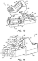
- FIG 10 shows a duplex fibre optic loopback connector 1'.
- the duplex fibre optic loopback connector 1' is similar to the duplex fibre optic connector 1, except that instead of having two optical fibres pass out of the connector (one for each connector plug, perhaps in a single insulated sheath as shown in Figure 9 ), a single optical fibre 65 passes directly from the first connector plug 10 to the second connector plug 10.
- the optical fibre is 900 ⁇ m optical fibre.
- the loop of optical fibre 65 may be arranged so as to attenuate the signal which passes therethrough. This may be achieved, for example, by tightly coiling the loop of optical fibre so as to cause a proportion of the light passing therethrough to be transmitted out of the optical fibre rather than undergoing total internal reflection within the optical fibre.
- the ends of the optical fibre may be roughened so that, when received by a socket, only a portion of the ends of the optical fibre make contact with an optical fibre in the corresponding socket.
- any alternative means for attenuating the signal may be employed.
- a fibre optic loopback connector may be provided with a specific level of attenuation such as 5 dB or 10 dB.
- An insignia 99 may be provided to identify the level of attenuation (if any) provided by the fibre optic loopback connector 1'.
- the insignia is provided in the form of a coloured push-fit plug which is received into a socket in an end of the loopback fibre optic connector 1' opposite the connector plugs.
- the insignia may, of course, be anything appropriate to identify the level of attenuation.
- the insignia may be an engraved marking, a portion of text, or an adhesive label.
- FIG 11 shows a duplex blanking plug 101 according to an embodiment of the invention.
- the duplex blanking plug 101 of the specific example shown in Figure 11 is similar to the fibre optic loopback connector 1' except that the optical fibre which runs down the axis of each connector plug is replaced by a similarly dimensioned cylindrical stopper 15.
- the blanking plug may be used to plug a socket when the socket is not being used to carry a signal.
- the stopper prevents the ingress of dirt and contaminants which may, if allowed to enter, degrade signal quality when the socket is again used with a fibre optic connector once the blanking plug has been removed. By avoiding the use of optical fibre for the blanking plug, the cost of the plug may be reduced.
- the stopper may be made from material with appropriate physical properties, such as plastic, rubber or metal.
- the blanking plug it is of course possible for the blanking plug to comprise optical fibre and/or spring means and/or a ceramic ferrule so long as the configuration of the blanking plug is not such as to provide an optical path.
- the blanking plug is provided with a guard which inhibits manual release of the blanking plug from a socket into which it is received, the blanking plug may only be removed using the corresponding tool.
- this prevents an unauthorised party from removing the blanking plug.
- This prevents an unauthorised party from inserting an unauthorised fibre optic connector into the fibre optic socket.
- the customer may be supplied with a patch board of sockets all of which are populated with a blanking plug.
- the guard of each blanking plug would render each blanking plug incapable of removal from its socket without the corresponding tool. This, in turn, prevents an unauthorised party from inserting an unauthorised fibre optic connector into any of the fibre optic sockets in the patch board.
- the preferred embodiment of the fibre optic connector comprises two connector plugs (in a duplex arrangement) each with a resilient leg and one guard cover over both legs
- the invention also encompasses a fibre optic connector comprising any number of connector plugs with any number of resilient legs and any number of guard covers.
- an embodiment of the invention may comprise a simplex connector comprising only one connector plug with only one resilient leg and one guard cover over that leg.
- a blanking plug 101 of the invention may be provided with any number of connector plugs 10 each provided with a stopper 15; the blanking plug 101 is not limited to a duplex arrangement.
- fibre optic loopback connector 1' of the invention must comprise at least two connector plugs 10 in order to provide the loop functionality, it is not necessarily limited to a duplex arrangement.
- the connector 1 of the present invention also encompasses embodiments which comprise any number of ramps 38.
- the guard cover of the fibre optic connector may have any number of protrusions and/or notches 35 and/or other obstructions located anywhere in the aperture formed partially by the guard cover including, but not limited to, the span 31 and the supports 32 of the bridge. Whatever the nature of the aperture, the tongue 130 of the tool is adapted to pass through the aperture in order to actuate the resilient legs 20.
- the tool 100 and cap 1000 are of course preferably adapted to the particular embodiment of the connector 1.
- the numbers of connector plugs 10 and resilient legs 20 of the connector 1 are accommodated by the features of the tool 100 and the cap 1000.
- an additional security feature is provided.
- the guard cover is arranged to extend in the first longitudinal direction (in other words, the direction of elongation of the plugs 10) at least to the location of a front face of the associated socket, when the plug 10 is fully inserted into the socket. This prevents access to the resilient leg (or legs) of the connector in its direction of depression. By providing this additional feature, accessing the resilient leg or legs at a location close to the front face of the associated socket is precluded.
- This additional security feature can implemented in a number of different ways, which will now be described.
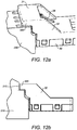
- FIG 12a there is shown a perspective view of a fibre optic connector and associated socket with a first embodiment of the additional security feature. Where the same features are indicated as in other figures, identical reference numerals have been used.
- a bar 300 is additionally provided with span 31. When the connector is engaged with an associated socket 200, the bar 300 sits above the socket 200. In this way, the bar 300 prevents access to the ends 23 of the resilient legs immediately adjacent the front face of the socket 200. The bar 300 extends along the full width of the connector.
- FIG. 12b A side view of the embodiment of Figure 12a is shown in Figure 12b .
- the connector is engaged with a keystone 210.
- a notch 215 may be provided in the keystone 210 in order to accommodate the bar 300.
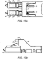
- FIG. 13a there is shown a top view of a fibre optic connector with a second embodiment of the additional security feature.
- Projections 310 are positioned adjacent to the span 31 in alignment with the ends 23 of the resilient legs in the longitudinal direction (the direction of elongation of the plugs 10). Again, the projections or protrusions 310 prevent access to the ends 23 of the resilient legs in their direction of depression.
- Figure 13b shows a side view of the embodiment of Figure 13a . Also, notches may be provided in an associated keystone to accommodate the projections 310, as with the embodiment shown in Figure 12b .
- FIG 14a there is shown a top view of a fibre optic connector with a third embodiment of the additional security feature.
- An insert 320 is provided adjacent the span 31 to prevent access to the ends 23 of the resilient legs in their direction of depression.
- the insert 320 is advantageously made from rubber. Again, it may extend across the whole width of the connector.
- Figure 14b shows a side view of the embodiment of Figure 14a . No modification is required to an associated keystone in order to accommodate the insert 320.
- FIG. 15a shows a top view of a fibre optic connector with such a fourth embodiment of the additional security feature.
- Lip 330 is provided adjacent the span 31 to prevent access to the ends 23 of the resilient legs in their direction of depression.
- Lip 330 may take the form of a flap, which may extend across the whole width of the connector.
- the lip 330 may be relatively thin.
- the lip may be integrally moulded with the guard cover. Again, no modification is required to an associated keystone in order to accommodate the lip 330.
- Figure 15b shows a side view of the embodiment of Figure 15a .
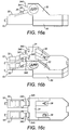
- FIG. 16a shows a side view of a fibre optic connector with such a fifth embodiment of the additional security feature. Flap 340 is provided adjacent the span 31 to prevent access to the ends 23 of the resilient legs in their direction of depression.
- FIG 16b shows a perspective view of the embodiment of Figure 16a . It can be seen that two flaps 340 are provided, one for each fibre optic connector plug 10. One end of each flap 340 is pivoted against the bridge span 31. The flaps 340 can therefore move with respect to the bridge span 31.
- the bridge span 31 extends closer to the front part of the connector plug 10 in the longitudinal direction than other embodiments.
- the bridge span 31 is further adapted with associated notches 345.
- the notches 345 are positioned such that the flaps 340 are pushed into the respective notches 345 when the fibre optic connector is inserted into a socket.
- the flaps 340 are shaped such that, when they are pushed into the notches 345, a portion of the flaps 340 extends in the longitudinal direction at least to the location of a front face of the associated socket.
- an end 341 of the flaps 340 is angled and shaped such that, when the flaps 340 are pushed into the notches 345, they extend in the longitudinal direction further forward than the bridge span 31.
- at least a part of each flap 340 is horizontal, that is parallel with the span 31.
- Figure 16c shows a top view of the embodiment of Figures 16a and 16b .
- the flaps 340 may be integrally moulded with the guard cover. Again, no modification is required to an associated keystone in order to accommodate the flaps 340, since they are pushed into the notches 345 when the connector is inserted into a socket.
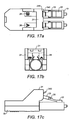
- FIG 17a shows a second embodiment of a blanking plug according to the invention in plan view.
- the blanking plug is similar to that shown in Figure 11 , but additionally incorporates the new features shown in Figures 16a to 16c .
- flaps 340 are provided, one for each fibre optic connector plug 10. One end of each flap 340 is pivoted against the bridge span 31.
- the bridge span 31 again extends closer to the front part of the connector plug 10 in the longitudinal direction than in the embodiment shown in Figure 11 .
- the bridge span 31 is further adapted with associated notches 345, positioned to allow the flaps 340 to be pushed into the respective notches 345 when the fibre optic connector is inserted into a socket.
- Figure 17b shows a rear end view of the embodiment of Figure 17a.
- Figure 17c shows a side view of the embodiment of Figure 17a .
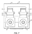
- Figure 17d shows a front end view of the embodiment of Figure 17a .
- Figure 17e shows a perspective view of the embodiment of Figure 17a .
- FIG 18 shows a blanking plate according to an embodiment of the present invention.
- Blanking plate 400 comprises: a first fibre optic connector 410; a second fibre optic connector 420; and a plate 430.
- the configuration of the blanking plate 400 means that when fibre optic connector 410 and fibre optic connector 420 are inserted into associated sockets, the plate 430 prevents any fibre optic connectors being inserted into the blocked sockets.
- the plate 330 is metal, but may alternatively be plastic or another material.
- the blanking plate may only be removed using a corresponding tool or tools to allow release of the first fibre optic connector 410 and the second fibre optic connector 420 from the respective sockets.
- the first fibre optic connector 410 and the second fibre optic connector 420 may be replaced by corresponding blanking plugs as appropriate.
- first fibre optic connector 410 and the second fibre optic connector 420 are also provided.
- first fibre optic connector 410 may be slid on runners to allow its position to be altered. This allows the blanking plate 400 to block different numbers of sockets or to block sockets where the spacing between them is not fixed or standard.
- Figure 19a shows a plan view of a tool for removing a fibre optic connector from an associated socket according to a second, preferred embodiment of the present invention.
- the tool is similar to that shown in Figure 3 and where the same features have been included, identical reference numerals have been used.
- Tool 100 further comprises a raised portion 140 of resilient arm 120.
- the raised portion 140 is coupled to the tool body 110 using a resilient bias 145 (for example, a spring).
- Figure 19b shows a rear end view of the tool of Figure 19a.
- Figure 19c shows a side view of the tool of Figure 19a .
- Figure 19d shows a front end view of the tool of Figure 19a .
- Figure 19e shows a perspective view of the tool of Figure 19a .
Landscapes
- Physics & Mathematics (AREA)
- General Physics & Mathematics (AREA)
- Optics & Photonics (AREA)
- Engineering & Computer Science (AREA)
- Manufacturing & Machinery (AREA)
- Mechanical Coupling Of Light Guides (AREA)
- Details Of Connecting Devices For Male And Female Coupling (AREA)
- Connector Housings Or Holding Contact Members (AREA)
Description
- An optical fibre connector is used to terminate the end of an optical fibre for connection into a socket. When the connector is received into a socket, the optical fibre in the connector meets with an optical fibre in the socket providing a direct interface between the two optical fibres.
- In many optical fibre connectors the means of connection to the socket is a snap fit. A latch mechanism is commonly employed such that when the latch is depressed the optical fibre connector is released from the push-fit connection with the socket. Applying pressure to the latch is quick and simple.
- Documents
US2009/047818 ,WO2007/016794 ,EP1450189 andUS2004/247252 provide optical connectors with latching mechanisms. - An example of a snap fit optical fibre connector is the Lucent Connector, commonly known as the LC connector.
Figure 1a shows a simplex LC connector whileFigure 1b shows a duplex LC connector. - Such a snap fit connector arrangement allows for simple reconfiguration of optical fibre paths, for example when wishing to redirect an optical fibre from one location to another.
- Against this background, the present invention provides a fibre optic connector according to the appended claims. The fibre optic connector comprises: a first connector plug, which may be inserted into an associated socket in a first longitudinal direction; a first resilient leg, depending at a first end thereof from the first connector plug, and having a depressible part, distal therefrom, depressible towards the first connector plug, the first resilient leg having one or more lugs formed thereupon for engagement with a flange of a fibre optic socket; and a guard cover, configured to prevent access to the depressible part of the first resilient leg in its direction of depression, but to permit access to the first resilient leg in the first longitudinal direction through an access aperture, the access aperture being aligned with the depressible part of the first resilient leg on an axis parallel with the first longitudinal direction, to allow depression of the first resilient leg through the access aperture directly.
- By aligning the access aperture with the depressible part of the resilient leg, it becomes possible to use a tool to depress the resilient directly. No intermediate pieces are therefore needed release the guard cover or to depress the resilient leg. This allows for easy manufacture of the connector and integral formation of the guard cover with the connector plug. Optionally, the resilient leg is also integrally formed with the connector plug. Moreover, the arrangement advantageously allows direct depression of the resilient leg using an associated tool, which provides secure protection to prevent depression of the resilient leg that is more robust to component failure, since a minimum number of moving parts are needed.
- Ancillary to the invention is a fibre optic connector comprising: a first connector plug; a first resilient leg depending from the first connector plug and having one or more lugs formed thereupon for engagement with a flange of a fibre optic socket; and a guard cover positioned over the first resilient leg to inhibit depression thereof.
- Preferably, the guard cover is positioned over the first resilient leg to inhibit manual depression thereof.
- The fibre optic connector of the present invention thus inhibits manual removal of the connector from a push-fit socket into which it has been received. Hence it increases security by inhibiting removal by unauthorised parties. This, in turn, provides increased data security.
- Advantageously, the connector of the present invention is compatible with standard pre-existing push-fit sockets.
- In one embodiment, the fibre optic connector further comprises: a second connector plug, which may be inserted into an associated socket in a first longitudinal direction; a second resilient leg, depending at a first end thereof from the second connector plug, and having a depressible part, distal therefrom, depressible towards the second connector plug, the second resilient leg having one or more lugs formed thereupon for engagement with a flange of a fibre optic socket; and a guard cover, configured to prevent access to the depressible parts of the first resilient leg and the second resilient leg in their directions of depression, but to permit access to the first resilient leg and the second resilient leg in the first longitudinal direction through at least one access aperture, the at least one access aperture being aligned with the depressible part of the first resilient leg on an axis parallel with the first longitudinal direction and being aligned with the depressible part of the second resilient leg on an axis parallel with the first longitudinal direction, to allow depression of the first resilient leg and second resilient leg through the at least one access aperture directly.
- In a second aspect, the present invention may be found in a fibre optic connector comprising: a first connector plug, a first resilient leg, depending at a first end thereof from the first connector plug, and having a depressible part, distal therefrom, depressible towards the first connector plug, the first resilient leg having one or more lugs formed thereupon for engagement with a flange of a fibre optic socket; and a guard cover, positioned over the first resilient leg to inhibit depression thereof and formed integrally with the first connector plug.
- Optionally, the guard cover is configured to prevent access to the depressible part of the first resilient leg in its direction of depression, but to permit access to the first resilient leg in the first longitudinal direction through an access aperture, the access aperture being aligned with the depressible part of the first resilient leg on an axis parallel with the first longitudinal direction, to allow depression of the first resilient leg through the access aperture directly.
- In one embodiment the fibre optic connector, further comprises: a second connector plug; a second resilient leg, depending at a first end thereof from the second connector plug, and having a depressible part distal therefrom, depressible towards the second connector plug, the second resilient leg having one or more lugs formed thereupon for engagement with a flange of the fibre optic socket; and the guard cover is positioned over the first resilient leg and the second resilient leg to inhibit depression thereof and formed integrally with the first connector plug and the second connector plug.
- Optionally, the guard cover is configured to prevent access to the depressible parts of the first resilient leg and the second resilient leg in their directions of depression, but to permit access to the first resilient leg and the second resilient leg in the first longitudinal direction through at least one access aperture, the at least one access aperture being aligned with the depressible part of the first resilient leg on an axis parallel with the first longitudinal direction and being aligned with the depressible part of the second resilient leg on an axis parallel with the first longitudinal direction, to allow depression of the first resilient leg and second resilient leg through the at least one access aperture directly.
- A number of features may be applicable to both first and second aspects of the present invention.
- Preferably, the first connector plug is elongate and the first resilient leg extends generally along the axis of elongation.
- Where the fibre optic connector has a second connector plug, it may be elongate and the second resilient leg extends generally along the axis of elongation.
- More preferably, the first and second connector plugs extend in a direction generally parallel with each other. Optionally, the first and second connector plugs are parallel with the said axis of elongation.
- Beneficially, the guard cover extends in the first longitudinal direction at least to the location of a front face of the associated socket, when the first connector plug is fully inserted into the associated socket, so as to prevent access to the first resilient leg in its direction of depression. This is so as to prevent access to the first resilient leg in its direction of depression. In particular, this mitigates the possibility of accessing the first resilient leg at a location close to the front face of the associated socket. Where a second connector plug is additionally used, the guard cover may also prevent access to the second resilient leg in its direction of depression.
- In some embodiments, the guard cover comprises a bridge over the first resilient leg, the bridge having supports surrounding the first resilient leg and a span joining the supports and spaced from the first resilient leg. Optionally, a region bounded by the bridge span, the bridge supports and the first connector plug defines an aperture. Preferably, the bridge further comprises at least one projection extending in the first longitudinal direction towards the first end of the first resilient leg to prevent access to the first resilient leg in its direction of depression. This prevents access to the first resilient leg at a location close to the front face of the associated socket.
- In the preferred embodiment, one end of the projection is pivoted to the bridge. Then, the bridge may optionally further comprise a notch arranged such that a force in the longitudinal direction against the projection causes it to be pushed into the notch in the bridge. Advantageously, the projection is configured such that at least a portion of the projection extends in the first longitudinal direction towards the first end of the first and second resilient legs to prevent access to the first and second resilient legs in their direction of depression when the projection is pushed into the notch. This may be achieved by shaping the end of the projection that is not pivoted to the bridge accordingly. For example, the non-pivoted end of the projection may comprise a surface that is substantially horizontal when the projection is pushed into the notch.
- Advantageously, the guard cover comprises a bridge over the first resilient leg, the bridge having supports surrounding the first resilient leg and a span joining the supports and spaced from the first resilient leg. Optionally, a region bounded by the bridge span, the bridge supports and the first connector plug defines the access aperture.
- Beneficially, a region bounded by the bridge span, the bridge supports, the first connector plug and the second connector plug defines the access aperture. Optionally, the access aperture is further bounded by a barrier adjacent to the bridge. Advantageously, the barrier is shaped to act as a guide towards the access aperture. Preferably, the barrier comprises at least one ramp.
- Preferably, the fibre optic connector further comprises a Radio Frequency Identification (RFID) tag.
- The present invention also provides for a kit comprising the connector as described herein and a tool, the tool comprising: a tool body; a resilient arm depending from the tool body; and a tongue formed upon or adjacent a distal end of the resilient arm and adapted to pass through the guard cover of the connector to engage directly and depress the one or more resilient legs of the connector.
- Preferably, in use, the tongue of the tool is adapted to pass inside the guard cover and urge against the one or more resilient legs of the connector. Optionally, the tongue of the tool is formed as a key comprising one or more notches and/or one or more protrusions.
- A further aspect of the present invention provides for a kit comprising: the fibre optic connector described herein; and a cap for removal of the tool from the guard cover of the fibre optic connector.
- More preferably, one or more of the kits of the present invention may further comprise a cap for removal of the tool from the guard cover of the fibre optic connector.
- In another aspect, there is provided a tool for releasing a fibre optic connector from an associated socket, comprising: a tool body defining an inner volume for receiving a portion of the fibre optic connector; a resilient arm depending from the tool body; and a tongue formed upon or adjacent a distal end of the resilient arm.
- Preferably, the tongue comprises at least one of: one or more notches; and one or more protrusions.
- In a further aspect, there is provided a cap for a fibre optic connector, the cap being generally elongate and comprising: a cap body that defines an inner volume for receiving a front portion of the fibre optic connector, having a plurality of electrical contacts; and an arm projecting from the cap body along the direction of elongation.
- Advantageously, the arm is ramp-shaped at its distal end. Preferably, the cap further comprises a flange for abutting a lug on the fibre optic connector. Optionally, the cap, further comprises a resilient clip depending from the cap body, and the flange is formed on the resilient clip.
- There is also provided a method of inhibiting removal of a fibre optic connector from a fibre optic socket, the method comprising the steps of: providing a fibre optic connector having: a connector plug, which may be inserted into the fibre optic socket in a longitudinal direction; and a resilient leg depending, at a first end from the connector plug and having a depressible part, distal therefrom, depressible towards the first connector plug, the resilient leg having one or more lugs formed thereupon for engagement with a flange of a fibre optic socket; and providing a guard cover upon the fibre optic connector, configured to prevent access to the depressible part of the first resilient leg in its direction of depression, but to permit access to the first resilient leg in the first longitudinal direction through an access aperture, the access aperture being aligned with the depressible part of the first resilient leg on an axis parallel with the first longitudinal direction, to allow depression of the first resilient leg through the access aperture directly.
- There is further provided a method of actuating a resilient leg of a fibre optic connector, the connector comprising: a connector plug, which may be inserted into an associated socket in a first longitudinal direction; a resilient leg depending at a first end thereof from the connector plug, and having a depressible part, distal therefrom, depressible towards the first connector plug, the first resilient leg having one or more lugs formed thereupon for engagement with a flange of a fibre optic socket and arranged such that its depressible part may be depressed towards the connector plug; and a guard cover, configured to prevent access to the depressible part of the first resilient leg in its direction of depression, but to permit access to the first resilient leg in the first longitudinal direction for its depression. The method comprises: passing a tool in the longitudinal direction of the connector plug, beneath the guard cover of the connector; and applying the tool directly to the depressible part of the resilient leg.
- Also, there is provided a kit comprising a fibre optic connector and an associated tool configured to carry this the method.
- In another aspect there is provided a method of extracting a fibre optic connector comprising a guard cover from a fibre optic socket, using a tool having a resilient leg and a tongue formed upon or adjacent a distal end of the resilient leg. The method comprises: passing the tongue through the guard cover of the connector; and directly engaging with and depressing the resilient leg of the connector.
- There is also provided a method of extracting a fibre optic connector from a socket, the fibre optic connector having a connector plug and a resilient leg depending from the connector plug, a proximal end of the resilient leg being engaged with the socket so as to prevent removal of the fibre optic connector from the socket. The method comprises: inserting an extraction tool into the fibre optic connector such that the extraction tool depresses the resilient leg directly and thereby disengages the resilient leg from the socket; and extracting the fibre optic connector from the socket.
- Preferably, the resilient leg has a depressible part distal from its proximal end, the fibre optic connector further comprises a guard cover, configured to prevent access to the depressible part of the resilient leg in its direction of depression, but to permit access to the resilient leg through an access aperture in a longitudinal direction, in which the connector plug can be inserted into a socket, the access aperture being aligned with the depressible part of the resilient leg on an axis parallel with the longitudinal direction, to allow depression of the resilient leg through the access aperture directly, and the step of inserting the extraction tool comprises accessing the resilient leg along that longitudinal direction.
- More preferably, the access aperture is defined by the resilient leg and the guard cover.
- In the preferred embodiment, the fibre optic connector further comprises a barrier element located adjacent the depressible part of the resilient leg, and the access aperture is defined by the resilient leg, the guard cover and the barrier element. Beneficially, the barrier is shaped to act as a guide towards the access aperture. Optionally, the barrier comprises at least one ramp.
- Advantageously, the extraction tool comprises a tongue. Then, the method may further comprises: aligning one or both of: projections; and notches on the tongue with corresponding one or both of: notches; and projections on the guard arrangement.
- Optionally, the step of inserting the extraction tool into the fibre optic connector comprises engaging the extraction tool with the fibre optic connector, said engagement preventing removal of the extraction tool from the fibre optic connector.
- Beneficially, the method may further comprise: disengaging the extraction tool from the fibre optic connector by inserting the fibre optic connector into one of: a socket; and a cap; and removing the extraction tool from the fibre optic connector.
- There is also disclosed a fibre optic loopback connector comprising: a first connector plug, which may be inserted into an associated socket in a first longitudinal direction; a first resilient leg, depending at a first end thereof from the first connector plug, and having a depressible part, distal therefrom, depressible towards the first connector plug, the first resilient leg having one or more lugs formed thereupon for engagement with a flange of a fibre optic socket; a second connector plug, which may be inserted into an associated socket in the first longitudinal direction; a second resilient leg, depending at a first end thereof from the second connector plug, and having a depressible part, distal therefrom, depressible towards the second connector plug, the second resilient leg having one or more lugs formed thereupon for engagement with a flange of a fibre optic socket; a guard cover, configured to prevent access to the depressible parts of the first resilient leg and the second resilient leg in their directions of depression, but to permit access to the first resilient leg and the second resilient leg in the first longitudinal direction through at least one access aperture, the at least one access aperture being aligned with the depressible part of the first resilient leg on an axis parallel with the first longitudinal direction and being aligned with the depressible part of the second resilient leg on an axis parallel with the first longitudinal direction, to allow depression of the first resilient leg and second resilient leg through the at least one access aperture directly; and an optical fibre having a first end and a second end. The first end is exposed at an end of the first connector plug and the second end is exposed at an end of the second connector plug such that the optical fibre provides a loop between the first plug and the second plug.
- In further aspect, there is also disclosed a fibre optic loopback connector comprising: a first connector plug; a first resilient leg, depending at a first end thereof from the first connector plug, and having a second end, distal therefrom, depressible towards the first connector plug, the first resilient leg having one or more lugs formed thereupon for engagement with a flange of a fibre optic socket; a second connector plug; a second resilient leg, depending at a first end thereof from the second connector plug, and having a depressible part, distal therefrom, depressible towards the second connector plug, the second resilient leg having one or more lugs formed thereupon for engagement with a flange of a fibre optic socket; a guard cover, positioned over the first resilient leg to inhibit depression thereof and formed integrally with the first connector plug; and an optical fibre having a first end and a second end. The first end is exposed at an end of the first connector plug and the second end is exposed at an end of the second connector plug such that the optical fibre provides a loop between the first plug and the second plug.
- In one embodiment, the optical fibre attenuates a signal which passes therethrough. Optionally, the fibre optic loopback connector further comprises an insignia associated with a particular coefficient of attenuation provided by the optical fibre.
- Optionally, the guard cover comprises a bridge over the first and second resilient legs, the bridge having supports surrounding the first and second resilient legs and a span joining the supports and spaced from the first and second resilient legs. Preferably, a region bounded by the bridge span, the bridge supports, the first connector plug and the second connector plug defines the access aperture. Optionally, the access aperture is further bounded by a barrier adjacent to the bridge. Advantageously, the barrier is shaped to act as a guide towards the access aperture; optionally, the barrier comprises at least one ramp.
- Preferably, the fibre optic loopback connector further comprises a Radio Frequency Identification (RFID) tag.
- Advantageously, the optical fibre is 900 µm optical fibre. Optionally, the optical fibre is 250 µm optical fibre.
- In a yet further aspect, there is disclosed a blanking plug for a fibre optic socket, the plug comprising: a first connector plug, which may be inserted into an associated socket in a first longitudinal direction; a first resilient leg, depending at a first end thereof from the first connector plug, and having a depressible part, distal therefrom, depressible towards the first connector plug, the first resilient leg having one or more lugs formed thereupon for engagement with a flange of a fibre optic socket; and a guard cover, configured to prevent access to the depressible part of the first resilient leg in its direction of depression, but to permit access to the first resilient leg in the first longitudinal direction through an access aperture, the access aperture being aligned with the depressible part of the first resilient leg on an axis parallel with the first longitudinal direction, to allow depression of the first resilient leg through the access aperture directly.
- There is also provided a blanking plug for a fibre optic socket, the plug comprising: a first connector plug; a first resilient leg, depending at a first end thereof from the first connector plug, and having a depressible part, distal therefrom, depressible towards the first connector plug, the first resilient leg having one or more lugs formed thereupon for engagement with a flange of a fibre optic socket; and a guard cover, positioned over the first resilient leg to inhibit depression thereof and formed integrally with the first connector plug.
- Preferably, the first connector plug comprises a stopper for engagement with a fibre optic socket.
- More preferably, the guard cover comprises a bridge over the first resilient leg, the bridge having supports surrounding the first resilient leg and a span joining the supports and spaced from the first resilient leg. Optionally, a region bounded by the bridge span, the bridge supports and the first connector plug defines the access aperture. Preferably, the access aperture is further bounded by a barrier adjacent to the bridge. Advantageously, the barrier is shaped to act as a guide towards the access aperture. Optionally, the barrier comprises at least one ramp. In the preferred embodiment, the underside of the bridge span has formed therein one or more notches and/or one or more protrusions.
- In the preferred embodiment, the blanking plug further comprises: a second connector plug; and a second resilient, depending at a first end thereof from the second connector plug, and having a depressible part, distal therefrom, depressible towards the second connector plug, the second resilient leg having one or more lugs formed thereupon for engagement with a flange of a fibre optic socket. The guard cover is positioned over the first and second resilient legs.
- Optionally, the second connector plug comprises a stopper for engagement with a fibre optic socket.
- In some embodiments, the blanking plug further comprises a Radio Frequency Identification (RFID) tag.
- In an alternative aspect, there may be provided a blanking plate comprising: a plate; at least one blanking plug as described herein, fitted on the plate such that the plate covers a plurality of fibre optic sockets when the at least one blanking plug is fitted into an associated socket.
- Optionally, the blanking plate further comprises a blanking plug mount for fixing the blanking plug to the plate, the blanking plug mount being arranged to allow adjustment of the position of the blanking plug on the plate. Beneficially, the blanking plug mount may comprise runners mounted on a hole in the plate and a sliding mechanism adapted to allow the blanking plug to slide within the hole of the plate.
- Also provided is a patch panel comprising a plurality of fibre optic sockets, wherein at least one of the fibre optic sockets is occupied either by a fibre optic loopback connector or by a blanking plug.
- In some embodiments, every one of the sockets is occupied by: a fibre optic loopback connector; a blanking plug; or a fibre optic connector.
- Optionally, at least one of the sockets is occupied by a blanking plug, wherein the blanking plug is as described herein. Additionally or alternatively, at least one of the sockets is occupied by a fibre optic loopback connector, wherein the fibre optic loopback connector is as described herein. Additionally or alternatively, at least one of the sockets is occupied by a fibre optic connector, wherein the fibre optic connector is as described herein.
- Advantageously, therefore, the patch panel may be provided to the customer fully populated so that the customer can be confident that only those with a corresponding removal tool can have removed the blanking plugs in order to accesses the sockets in the patch panel.
- Embodiments of the present invention will now be described, by way of example only, with reference to the accompanying drawings, in which:
-
Figure 1a shows a perspective view of a prior art simplex LC connector; -
Figure 1b shows a perspective view of a prior art duplex LC connector; -
Figure 2 shows a perspective view of an embodiment of the fibre optic connector of the present invention; -
Figure 3 shows a perspective view of a tool embodying the present invention shown adjacent to the fibre optic connector ofFigure 2 ; -
Figure 4 shows the fibre optic connector ofFigure 2 together with an embodiment of a cap of the present invention; -
Figure 5 shows a plan view of the fibre optic connector ofFigure 2 ; -
Figure 6 shows a side view of the fibre optic connector ofFigure 2 ; -
Figure 7 shows an end view of the fibre optic connector ofFigure 2 ; -
Figure 8 shows a plan view (from the opposite direction to that ofFigure 5 ) of the fibre optic connector ofFigure 2 ; -
Figure 9 shows an exploded perspective view of the connector ofFigure 2 ; -
Figure 10 shows an exploded perspective view of a fibre optic loopback connector according to an embodiment of the invention; -
Figure 11 shows a perspective view blanking plug according to an embodiment of the invention; -
Figure 12a shows a perspective view of a fibre optic connector and associated socket with a first additional security feature according to an embodiment of the invention; -
Figure 12b shows a side view of the fibre optical connector embodiment ofFigure 12a when engaged with a keystone; -
Figure 13a shows a top view of a fibre optic connector with a second additional security feature according to an embodiment of the invention; -
Figure 13b shows a side view of the embodiment ofFigure 13a ; -
Figure 14a shows a top view of a fibre optic connector with a third additional security feature according to an embodiment of the invention; -
Figure 14b shows a side view of the embodiment ofFigure 14a ; -
Figure 15a shows a top view of a fibre optic connector with a fourth additional security feature according to an embodiment of the invention; -
Figure 15b shows a side view of the embodiment ofFigure 15a ; -
Figure 16a shows a side view of a fibre optic connector with a fifth additional security feature according to an embodiment of the invention; -
Figure 16b shows a perspective view of the embodiment ofFigure 16a ; -
Figure 16c shows a top view of the embodiment ofFigure 16a ; -
Figure 17a shows a plan view of a second embodiment of a blanking plug in accordance with the present invention; -
Figure 17b shows a rear end view of the blanking plug ofFigure 17a ; -
Figure 17c shows a side view of the blanking plug ofFigure 17a . -
Figure 17d shows a front end view of the blanking plug ofFigure 17a ; -
Figure 17e shows a perspective view of the blanking plug ofFigure 17a ; -
Figure 18 shows a blanking plate in accordance with the present invention; -
Figure 19a shows a plan view of a second embodiment of a tool for removing a fibre optic connector in accordance with the present invention; -
Figure 19b shows a rear end view of the embodiment ofFigure 19a ; -
Figure 19c shows a side view of the embodiment ofFigure 19a ; -
Figure 19d shows a front end view of the embodiment ofFigure 19a ; and -
Figure 19e shows a perspective view of the embodiment ofFigure 19a . - A fibre optic connector embodying the present invention is shown in
Figure 2 (and, in exploded form, inFigure 9 ). The fibre optic connector 1 has ahousing 50 and two connector plugs 10. - The
housing 50 comprises alower part 51 and anupper part 52. Thehousing 50 encapsulates the proximal ends of the connector plugs 10 between thelower part 51 and theupper part 52. Thelower part 51 andupper part 52 snap fit together. Theupper part 52 of thehousing 50 includes an integrally mouldedguard cover 30 - Each
connector plug 10 is elongate and comprises aresilient leg 20 which depends at one end of theleg 20 from an end of theconnector plug 10 opposite to thehousing 50. Eachresilient leg 20 extends generally along the axis of elongation of theconnector plug 10. Alug 25 is formed on each side of eachresilient leg 20 so as to protrude from theleg 20 in an direction perpendicular to the axis of elongation. - The
guard cover 30 is positioned over theends 23 of the resilient legs away from theends 22 at which eachresilient leg 20 depends from theconnector plug 10. - The
guard cover 30 comprises a bridge with aspan 31 and twosupports 32. Thespan 31 covers both resilient legs. The supports 32 are located at the ends of thespan 31. On the underside of thespan 31 there is formed one or more protrusions and/or one or more notches 35. - The
guard cover 30 further comprises tworamps 38 on the side of theguard cover 30 opposite theresilient legs 20 of the connector plugs 10. - A region bounded by the
bridge span 31, the bridge supports 32 and the two connector plugs defines an aperture. - Two
optical fibres 60 pass through thehousing 50 before each is received into one of the two connector plugs 10. - In use, the optical fibre connector 1 is received into a fibre optic socket (not shown). On entry into the socket, the ends 23 of the
resilient legs 20 are forced downwards towards the connector plugs by the perimeter of the socket. Once thelugs 25 formed on theresilient legs 20 have moved downwards sufficiently to allow entry of the connector plugs into the socket, theresilient legs 20 spring back so that thelugs 25 are restrained by a flange in the socket which inhibits removal of the connector 1 from the socket. - Subsequent removal of the connector 1 from the socket is achieved by depressing the ends 23 of the
resilient legs 20 such that thelugs 25 pass below the restraining flange of the socket. Since the ends 23 of theresilient legs 20 are located under the guard cover, however, it is not possible to depress theresilient legs 20 manually. Instead, in order to remove the connector 1 from the socket, it is necessary to use a corresponding removal tool. -
Figure 3 shows thetool 100 of the present invention alongside the fibre optic connector 1 ofFigure 2 . - The
tool 100 comprises atool body 110, aresilient arm 120 depending from the tool body and atongue 130 formed at the distal end of the resilient arm. Thetool body 110 includes a recess adapted so that, when in use, it will at least partly surround anoptical fibre 60 connected to the fibre optic connector 1. Theresilient arm 120 is typically more resilient than theresilient leg 10 of the connector 1. The shape of thetongue 130 is adapted to fit through (match) the aperture under the bridge span. In particular, where thebridge span 31 or supports 32 include one or more protrusions and/or one or more notches 35, the shape of the tongue is adapted to cooperate with the one or more protrusions and/or one or more notches 35. - In use, the
tool 100 is positioned parallel to the elongate direction of the connector plugs on the side of theguard cover 30 away from theresilient legs 20. The tool is aligned by ensuring that the optical fibre is at least partly enclosed by the recess of thetool 100. - The
tool 100 is then moved in a forward direction generally parallel to the direction of elongation, towards theguard cover 30. Theresilient arm 120 of thetool 100 makes contact with the tworamps 38 of the connector. Further movement in that forward direction causes the resilient arm of thetool 100 to slide up theramps 38. As stated above, the key 130 is adapted to fit through the aperture beneath thebridge span 31. Continued movement of thetool 100 will cause thetongue 130 to pass through the aperture beneath thebridge span 31. Once thetongue 130 has passed through the aperture, thetongue 130 makes contact with theresilient legs 20 of the connector 1. Since the resilience of theresilient arm 120 of thetool 100 is typically greater that the resilience of theresilient legs 20 of the connector 1, theresilient arm 120 forces theresilient legs 20 downwards towards the connector plugs 10. Hence, the connector 1 is then removable from the socket through downward movement of thelugs 25 in the manner described above. - Once the connector 1 has been removed from the socket, the
tool 100 remains attached to the connector 1 because thetongue 130 of thetool 100 remains on the leg side of theguard cover 30. Since the resilient arm of thetool 100 is more resilient than theresilient legs 20 of the connector 1, the tool cannot easily be removed from the connector 1. - There is also preferably provided, therefore, a
cap 1000 as illustrated inFigure 4 . Thecap 1000 comprises acap ramp 1010 mounted at one end of thecap 1000 and twoapertures 1020 adapted to receive the two connector plugs 10 of the connector 1. The cap further comprises aresilient clip 1030. - In use, the
cap 1000 is moved towards the connector plugs 10 in a direction so as to receive the connector plugs 10 into theapertures 1020 of thecap 1000. In consequence of this movement, thecap ramp 1010 slides underneath thetongue 130 at the distal end of theresilient arm 120 of theextraction tool 100. With continued movement in the same direction thetongue 130 is forced up by theramp 1010 which, in turn, forces theresilient arm 120 of thetool 100 up towards the aperture beneath thebridge span 31. Once theresilient arm 120 of thetool 100 is in line with the aperture beneath thebridge span 31 thetool 100 can be removed simply by moving thetool 100 in the direction of theoptical fibre 60 away from the connector 1. - Also in consequence of the movement of the cap, the
resilient legs 10 of the connector 1 are received beneath theresilient clip 1030 of thecap 1000 which holds thecap 1000 in place on the end of the connector 1. Thus, the cap will, by default, remain in place on the end of the fibre optic connector when the connector is not connected to a socket. - The connector, tool and cap may be made from a thermosetting plastic.
- Since a very large number of arrangements of connector guard cover apertures is contemplated by the invention and each such arrangement has at least one corresponding tool, it may be that the corresponding connector and tool include some means of identification in order for the user easily to identify the correspondence between connector and tool. For example, corresponding connectors and tools may be formed in the same colour. The cap may also be formed in the same colour.
- The
housing 50 of the fibre optic connector 1 may comprise any number of components. The connector plugs 10 may be formed from thehousing 50. Thehousing 50 may include a recess 53 for receiving a Radio Frequency Identification (RFID) tag. -
Figure 10 shows a duplex fibre optic loopback connector 1'. The duplex fibre optic loopback connector 1' is similar to the duplex fibre optic connector 1, except that instead of having two optical fibres pass out of the connector (one for each connector plug, perhaps in a single insulated sheath as shown inFigure 9 ), a singleoptical fibre 65 passes directly from thefirst connector plug 10 to thesecond connector plug 10. In use, therefore, when the duplex loopback connector 1' is received by a duplex socket, the signal from a first socket of the duplex socket will pass via the loop to a second socket of the duplex socket. In the specific example, the optical fibre is 900 µm optical fibre. - The loop of
optical fibre 65 may be arranged so as to attenuate the signal which passes therethrough. This may be achieved, for example, by tightly coiling the loop of optical fibre so as to cause a proportion of the light passing therethrough to be transmitted out of the optical fibre rather than undergoing total internal reflection within the optical fibre. Alternatively, the ends of the optical fibre may be roughened so that, when received by a socket, only a portion of the ends of the optical fibre make contact with an optical fibre in the corresponding socket. Of course, any alternative means for attenuating the signal may be employed. - A fibre optic loopback connector may be provided with a specific level of attenuation such as 5 dB or 10 dB.
- An
insignia 99 may be provided to identify the level of attenuation (if any) provided by the fibre optic loopback connector 1'. In the embodiment illustrated inFigure 10 , the insignia is provided in the form of a coloured push-fit plug which is received into a socket in an end of the loopback fibre optic connector 1' opposite the connector plugs. The insignia may, of course, be anything appropriate to identify the level of attenuation. For example, the insignia may be an engraved marking, a portion of text, or an adhesive label. -
Figure 11 shows aduplex blanking plug 101 according to an embodiment of the invention. Theduplex blanking plug 101 of the specific example shown inFigure 11 is similar to the fibre optic loopback connector 1' except that the optical fibre which runs down the axis of each connector plug is replaced by a similarly dimensionedcylindrical stopper 15. The blanking plug may be used to plug a socket when the socket is not being used to carry a signal. When the blanking plug is in use with a socket, the stopper prevents the ingress of dirt and contaminants which may, if allowed to enter, degrade signal quality when the socket is again used with a fibre optic connector once the blanking plug has been removed. By avoiding the use of optical fibre for the blanking plug, the cost of the plug may be reduced. It is also possible to avoid the need for spring means which are commonly used in LC connectors in order to ensure intimate contact of the fibre optic in the plug with the fibre optic in the socket. It is also not necessary to provide a ceramic ferrule which is commonly used in LC connectors to terminate the optical fibre. These provide further cost savings. The stopper may be made from material with appropriate physical properties, such as plastic, rubber or metal. However, it is of course possible for the blanking plug to comprise optical fibre and/or spring means and/or a ceramic ferrule so long as the configuration of the blanking plug is not such as to provide an optical path. - Where the blanking plug is provided with a guard which inhibits manual release of the blanking plug from a socket into which it is received, the blanking plug may only be removed using the corresponding tool. Advantageously, therefore, this prevents an unauthorised party from removing the blanking plug. This, in turn, prevents an unauthorised party from inserting an unauthorised fibre optic connector into the fibre optic socket.
- Furthermore, the customer may be supplied with a patch board of sockets all of which are populated with a blanking plug. The guard of each blanking plug would render each blanking plug incapable of removal from its socket without the corresponding tool. This, in turn, prevents an unauthorised party from inserting an unauthorised fibre optic connector into any of the fibre optic sockets in the patch board.
- While it will be noted that the preferred embodiment of the fibre optic connector comprises two connector plugs (in a duplex arrangement) each with a resilient leg and one guard cover over both legs, the invention, of course, also encompasses a fibre optic connector comprising any number of connector plugs with any number of resilient legs and any number of guard covers. In particular, an embodiment of the invention may comprise a simplex connector comprising only one connector plug with only one resilient leg and one guard cover over that leg.
- Similarly, a blanking
plug 101 of the invention may be provided with any number of connector plugs 10 each provided with astopper 15; the blankingplug 101 is not limited to a duplex arrangement. - While a fibre optic loopback connector 1' of the invention must comprise at least two connector plugs 10 in order to provide the loop functionality, it is not necessarily limited to a duplex arrangement.
- The connector 1 of the present invention also encompasses embodiments which comprise any number of
ramps 38. - The guard cover of the fibre optic connector may have any number of protrusions and/or notches 35 and/or other obstructions located anywhere in the aperture formed partially by the guard cover including, but not limited to, the
span 31 and thesupports 32 of the bridge. Whatever the nature of the aperture, thetongue 130 of the tool is adapted to pass through the aperture in order to actuate theresilient legs 20. - The
tool 100 andcap 1000 are of course preferably adapted to the particular embodiment of the connector 1. For example, it is necessary that the numbers of connector plugs 10 andresilient legs 20 of the connector 1 are accommodated by the features of thetool 100 and thecap 1000. - In the case where there is more than one connector plug and more than one resilient leg, there may be an additional component which joins two or more of the resilient legs.
- In preferred embodiments, an additional security feature is provided. Specifically, the guard cover is arranged to extend in the first longitudinal direction (in other words, the direction of elongation of the plugs 10) at least to the location of a front face of the associated socket, when the
plug 10 is fully inserted into the socket. This prevents access to the resilient leg (or legs) of the connector in its direction of depression. By providing this additional feature, accessing the resilient leg or legs at a location close to the front face of the associated socket is precluded. This additional security feature can implemented in a number of different ways, which will now be described. - In
Figure 12a , there is shown a perspective view of a fibre optic connector and associated socket with a first embodiment of the additional security feature. Where the same features are indicated as in other figures, identical reference numerals have been used. Abar 300 is additionally provided withspan 31. When the connector is engaged with an associatedsocket 200, thebar 300 sits above thesocket 200. In this way, thebar 300 prevents access to theends 23 of the resilient legs immediately adjacent the front face of thesocket 200. Thebar 300 extends along the full width of the connector. - A side view of the embodiment of
Figure 12a is shown inFigure 12b . In this view, the connector is engaged with akeystone 210. Anotch 215 may be provided in thekeystone 210 in order to accommodate thebar 300. - Rather than providing a
bar 300, other kinds of projections may be alternatively employed. InFigure 13a , there is shown a top view of a fibre optic connector with a second embodiment of the additional security feature.Projections 310 are positioned adjacent to thespan 31 in alignment with theends 23 of the resilient legs in the longitudinal direction (the direction of elongation of the plugs 10). Again, the projections orprotrusions 310 prevent access to theends 23 of the resilient legs in their direction of depression.Figure 13b shows a side view of the embodiment ofFigure 13a . Also, notches may be provided in an associated keystone to accommodate theprojections 310, as with the embodiment shown inFigure 12b . - In
Figure 14a , there is shown a top view of a fibre optic connector with a third embodiment of the additional security feature. Aninsert 320 is provided adjacent thespan 31 to prevent access to theends 23 of the resilient legs in their direction of depression. Theinsert 320 is advantageously made from rubber. Again, it may extend across the whole width of the connector.Figure 14b shows a side view of the embodiment ofFigure 14a . No modification is required to an associated keystone in order to accommodate theinsert 320. - In a fourth alternative embodiment of the additional security feature a lip is provided.
Figure 15a shows a top view of a fibre optic connector with such a fourth embodiment of the additional security feature.Lip 330 is provided adjacent thespan 31 to prevent access to theends 23 of the resilient legs in their direction of depression.Lip 330 may take the form of a flap, which may extend across the whole width of the connector. Advantageously, thelip 330 may be relatively thin. Also, the lip may be integrally moulded with the guard cover. Again, no modification is required to an associated keystone in order to accommodate thelip 330.Figure 15b shows a side view of the embodiment ofFigure 15a . - In a fifth alternative embodiment of the additional security feature at least one flap is provided.
Figure 16a shows a side view of a fibre optic connector with such a fifth embodiment of the additional security feature.Flap 340 is provided adjacent thespan 31 to prevent access to theends 23 of the resilient legs in their direction of depression. -
Figure 16b shows a perspective view of the embodiment ofFigure 16a . It can be seen that twoflaps 340 are provided, one for each fibreoptic connector plug 10. One end of eachflap 340 is pivoted against thebridge span 31. Theflaps 340 can therefore move with respect to thebridge span 31. - Also, the
bridge span 31 extends closer to the front part of theconnector plug 10 in the longitudinal direction than other embodiments. Thebridge span 31 is further adapted with associatednotches 345. Thenotches 345 are positioned such that theflaps 340 are pushed into therespective notches 345 when the fibre optic connector is inserted into a socket. - The
flaps 340 are shaped such that, when they are pushed into thenotches 345, a portion of theflaps 340 extends in the longitudinal direction at least to the location of a front face of the associated socket. In particular, anend 341 of theflaps 340 is angled and shaped such that, when theflaps 340 are pushed into thenotches 345, they extend in the longitudinal direction further forward than thebridge span 31. Also, at least a part of eachflap 340 is horizontal, that is parallel with thespan 31. These features prevent access to the resilient legs at a location close to the front face of the associated socket. -
Figure 16c shows a top view of the embodiment ofFigures 16a and 16b . Advantageously, theflaps 340 may be integrally moulded with the guard cover. Again, no modification is required to an associated keystone in order to accommodate theflaps 340, since they are pushed into thenotches 345 when the connector is inserted into a socket. -
Figure 17a shows a second embodiment of a blanking plug according to the invention in plan view. The blanking plug is similar to that shown inFigure 11 , but additionally incorporates the new features shown inFigures 16a to 16c . Specifically, flaps 340 are provided, one for each fibreoptic connector plug 10. One end of eachflap 340 is pivoted against thebridge span 31. - The
bridge span 31 again extends closer to the front part of theconnector plug 10 in the longitudinal direction than in the embodiment shown inFigure 11 . Thebridge span 31 is further adapted with associatednotches 345, positioned to allow theflaps 340 to be pushed into therespective notches 345 when the fibre optic connector is inserted into a socket. -
Figure 17b shows a rear end view of the embodiment ofFigure 17a. Figure 17c shows a side view of the embodiment ofFigure 17a .Figure 17d shows a front end view of the embodiment ofFigure 17a .Figure 17e shows a perspective view of the embodiment ofFigure 17a . -
Figure 18 shows a blanking plate according to an embodiment of the present invention.Blanking plate 400 comprises: a firstfibre optic connector 410; a secondfibre optic connector 420; and aplate 430. The configuration of theblanking plate 400 means that whenfibre optic connector 410 andfibre optic connector 420 are inserted into associated sockets, theplate 430 prevents any fibre optic connectors being inserted into the blocked sockets. Also shown inFigure 18 are associated socket panel 350 and further fibre optic connectors 1. Theplate 330 is metal, but may alternatively be plastic or another material. - Where the first
fibre optic connector 410 and the secondfibre optic connector 420 are provided with a guard cover which inhibits manual release of the fibre optic connectors from the sockets, the blanking plate may only be removed using a corresponding tool or tools to allow release of the firstfibre optic connector 410 and the secondfibre optic connector 420 from the respective sockets. Advantageously, therefore, this prevents an unauthorised party from removing theblanking plate 400. The firstfibre optic connector 410 and the secondfibre optic connector 420 may be replaced by corresponding blanking plugs as appropriate. - Means for adjusting the positioning of first
fibre optic connector 410 and the secondfibre optic connector 420 with respect to the plate are also provided. For example, the firstfibre optic connector 410 may be slid on runners to allow its position to be altered. This allows theblanking plate 400 to block different numbers of sockets or to block sockets where the spacing between them is not fixed or standard. -
Figure 19a shows a plan view of a tool for removing a fibre optic connector from an associated socket according to a second, preferred embodiment of the present invention. The tool is similar to that shown inFigure 3 and where the same features have been included, identical reference numerals have been used. -
Tool 100 further comprises a raisedportion 140 ofresilient arm 120. The raisedportion 140 is coupled to thetool body 110 using a resilient bias 145 (for example, a spring).Figure 19b shows a rear end view of the tool ofFigure 19a. Figure 19c shows a side view of the tool ofFigure 19a .Figure 19d shows a front end view of the tool ofFigure 19a .Figure 19e shows a perspective view of the tool ofFigure 19a .
Claims (26)
- A fibre optic connector (1) comprising:a first connector plug (10), having an insertion end for insertion into an associated socket in a first longitudinal direction, and a rear end opposite the insertion end;a first resilient leg (20), depending at a first end (22) thereof from the insertion end of the first connector plug, and having a depressible part (23), distal therefrom, depressible towards the first connector plug, the first resilient leg having one or more lugs (25) formed thereupon for engagement with a flange of a fibre optic socket; anda guard cover (30), configured to prevent access to the depressible part of the first resilient leg in its direction of depression, but to permit access to the depressible part of the first resilient leg in the first longitudinal direction through an access aperture accessible from the rear end of the first connector plug, the access aperture being aligned with the depressible part of the first resilient leg on an axis parallel with the first longitudinal direction, to allow depression of the first resilient leg through the access aperture directly;wherein the guard cover comprises a bridge over the first resilient leg, wherein a region bounded by the bridge and the first connector plug defines the access aperture, and wherein the access aperture is further bounded by at least one ramp (38) adjacent to the bridge.
- The fibre optic connector of claim 1, further comprising:a second connector plug (10), having an insertion end for insertion into an associated socket in a first longitudinal direction, and a rear end opposite the insertion end;a second resilient leg (20), depending at a first end (22) thereof from the insertion end of the second connector plug, and having a depressible part (23), distal therefrom, depressible towards the second connector plug, the second resilient leg having one or more lugs (25) formed thereupon for engagement with a flange of a fibre optic socket; andthe guard cover (30), being configured to prevent access to the depressible parts of the first resilient leg and the second resilient leg in their directions of depression, but to permit access to the depressible part of the first resilient leg and the second resilient leg in the first longitudinal direction through at least one access aperture accessible from the rear end of the first connector plug, the at least one access aperture being aligned with the depressible part of the first resilient leg on an axis parallel with the first longitudinal direction and being aligned with the depressible part of the second resilient leg on an axis parallel with the first longitudinal direction, to allow depression of the first resilient leg and second resilient leg through the at least one access aperture directly;wherein the guard cover comprises a bridge over the first and second resilient legs, wherein the region bounded by the bridge, the first connector plug and the second connector plug defines the access aperture, wherein the access aperture is further bounded by the at least one ramp adjacent to the bridge.
- A fibre optic connector (1) comprising:a first connector plug (10), having an insertion end for insertion into an associated socket in a first longitudinal direction,a first resilient leg (20), depending at a first end (22) thereof from the insertion end of the first connector plug, and having a depressible part (23), distal therefrom, depressible towards the first connector plug, the first resilient leg having one or more lugs (25) formed thereupon for engagement with a flange of a fibre optic socket; anda guard cover (30), positioned over the first resilient leg to inhibit depression thereof and formed integrally with the first connector plug, wherein the guard cover comprises a bridge over the first resilient leg, wherein a region bounded by the bridge and the first connector plug defines an access aperture to allow depression of the first resilient leg through the access aperture directly, wherein the access aperture is further bounded by at least one ramp (38) adjacent to the bridge.
- The fibre optic connector of claim 3, wherein the guard cover is configured to prevent access to the depressible part of the first resilient leg in its direction of depression, but to permit access to the depressible part of the first resilient leg in the first longitudinal direction through an access aperture, the access aperture being aligned with the depressible part of the first resilient leg on an axis parallel with the first longitudinal direction, to allow depression of the first resilient leg through the access aperture directly.
- The fibre optic connector of claim 3 or claim 4, further comprising:a second connector plug (10), having an insertion end for insertion into an associated socket in a first longitudinal direction;a second resilient leg (20), depending at a first end (22) thereof from the insertion end of the second connector plug, and having a depressible part (23) distal therefrom, depressible towards the second connector plug, the second resilient leg having one or more lugs (25) formed thereupon for engagement with a flange of the fibre optic socket; andwherein the guard cover is positioned over the first resilient leg and the second resilient leg to inhibit depression thereof and formed integrally with the first connector plug and the second connector plug, wherein the guard cover comprises the bridge over the first and second resilient legs, wherein a region bounded by the bridge, the first connector plug and the second connector plug defines at least one access aperture to allow depression of the first resilient leg through the access aperture directly, wherein the at least one access aperture is further bounded by the at least one ramp adjacent to the bridge.
- The fibre optic connector of claim 5, wherein the guard cover is configured to prevent access to the depressible parts of the first resilient leg and the second resilient leg in their directions of depression, but to permit access to the depressible part of the first resilient leg and the second resilient leg in the first longitudinal direction through the least one access aperture, the at least one access aperture being aligned with the depressible part of the first resilient leg on an axis parallel with the first longitudinal direction and being aligned with the depressible part of the second resilient leg on an axis parallel with the first longitudinal direction, to allow depression of the first resilient leg and second resilient leg through the at least one access aperture directly.
- The fibre optic connector of any preceding claim wherein the first connector plug is elongate and the first resilient leg extends generally along the axis of elongation.
- The fibre optic connector of any one of claims 2, 5 or 6 wherein the second connector plug is elongate and the second resilient leg extends generally along the axis of elongation.
- The fibre optic connector of any of claims 2, 5, 6 or 8 wherein the first and second connector plugs extend in a direction generally parallel with each other.
- The fibre optic connector of claim 9 wherein the first and second connector plugs are parallel with the said axis of elongation.
- The fibre optic connector of any preceding claim, wherein the guard cover extends in the first longitudinal direction at least to a location of a front face of the associated socket, when the first connector plug is fully inserted into the associated socket, so as to prevent access to the first resilient leg in its direction of depression.
- The fibre optic connector of any preceding claim wherein the bridge comprising supports (32) surrounding the first resilient leg and a span (31) joining the supports and spaced from the first resilient leg.
- The fibre optic connector of claim 12, when dependent upon claim 11, wherein the bridge further comprises at least one projection (310,320,330,340) extending in the first longitudinal direction towards the first end of the first resilient leg to prevent access to the first resilient leg in its direction of depression.
- The fibre optic connector of claim 12 or claim 13 wherein the access aperture is defined by the region bounded by the bridge span, the bridge supports and the first connector plug.
- The fibre optic connector of any of claims 2, 5, 6 or 8 to 10 wherein the bridge comprises supports (32) surrounding the first and second resilient legs and a span joining the supports and spaced from the first and second resilient legs.
- The fibre optic connector of claim 15, when dependent upon claim 11, wherein the bridge further comprises at least one projection (310,320,330,340) extending in the first longitudinal direction towards the first end of the first and second resilient legs to prevent access to the first and second resilient legs in their direction of depression.
- The fibre optic connector of claim 16, wherein one end of the projection (340) is pivoted to the bridge, the bridge further comprising a notch (345) arranged such that a force in the longitudinal direction against the projection causes it to be pushed into the notch in the bridge.
- The fibre optic connector of claim 17, wherein the projection is configured such that at least a portion of the projection extends in the first longitudinal direction towards the first end of the first and second resilient legs to prevent access to the first and second resilient legs in their direction of depression when the projection is pushed into the notch.
- The fibre optic connector of any one of claims 15 to 18 wherein the access aperture is bounded by the bridge span, the bridge supports, the first connector plug and the second connector plug.
- The fibre optic connector of any of claims 12 to 19 wherein the underside of the bridge span has formed therein one or more notches and/or one or more protrusions (35).
- The fibre optic connector of any preceding claim further comprising a Radio Frequency Identification (RFID) tag.
- A kit comprising the connector of any preceding claim and a tool (100), the tool comprising:a tool body (110);a resilient arm (120) depending from the tool body; anda tongue (130) formed upon or adjacent a distal end of the resilient arm and adapted to pass through the guard cover of the connector to engage directly and depress the one or more resilient legs of the connector.
- The kit of claim 22 wherein, in use, the tongue of the tool is adapted to pass inside the guard cover and urge against the one or more resilient legs of the connector.
- The kit of claim 22 or claim 23 wherein the tongue of the tool is formed as a key comprising one or more notches and/or one or more protrusions.
- The kit of any of claims 22 to 24 kit comprising:the fibre optic connector of any of claims 1 to 21; anda cap (1000) for removal of the tool from the guard cover of the fibre optic connector.
- The kit of any of claims 22 to 24 further comprising a cap (1000) for removal of the tool from the guard cover of the fibre optic connector.
Priority Applications (1)
| Application Number | Priority Date | Filing Date | Title |
|---|---|---|---|
| PL10706319T PL2401642T3 (en) | 2009-02-26 | 2010-02-26 | Fibre optic connector assembly and access tool kit |
Applications Claiming Priority (4)
| Application Number | Priority Date | Filing Date | Title |
|---|---|---|---|
| GB0903326A GB2463332B (en) | 2009-02-26 | 2009-02-26 | Fibre optic connector assembly |
| GBGB0915728.0A GB0915728D0 (en) | 2009-02-26 | 2009-09-08 | Fibre optic connector assembly and ancillary devices |
| GBGB0917235.4A GB0917235D0 (en) | 2009-02-26 | 2009-10-01 | Modular connector |
| PCT/GB2010/000356 WO2010097602A1 (en) | 2009-02-26 | 2010-02-26 | Fibre optic connector assembly and access tool kit |
Publications (2)
| Publication Number | Publication Date |
|---|---|
| EP2401642A1 EP2401642A1 (en) | 2012-01-04 |
| EP2401642B1 true EP2401642B1 (en) | 2019-02-13 |
Family
ID=40565801
Family Applications (3)
| Application Number | Title | Priority Date | Filing Date |
|---|---|---|---|
| EP10706721.7A Active EP2401791B1 (en) | 2009-02-26 | 2010-02-26 | Modular connector |
| EP16181332.4A Active EP3148007B1 (en) | 2009-02-26 | 2010-02-26 | Modular connector |
| EP10706319.0A Active EP2401642B1 (en) | 2009-02-26 | 2010-02-26 | Fibre optic connector assembly and access tool kit |
Family Applications Before (2)
| Application Number | Title | Priority Date | Filing Date |
|---|---|---|---|
| EP10706721.7A Active EP2401791B1 (en) | 2009-02-26 | 2010-02-26 | Modular connector |
| EP16181332.4A Active EP3148007B1 (en) | 2009-02-26 | 2010-02-26 | Modular connector |
Country Status (12)
| Country | Link |
|---|---|
| US (3) | US8783968B2 (en) |
| EP (3) | EP2401791B1 (en) |
| KR (2) | KR101723990B1 (en) |
| CN (4) | CN102414933B (en) |
| AU (4) | AU2010217370B2 (en) |
| BR (2) | BRPI1008313B1 (en) |
| CA (2) | CA2753659C (en) |
| ES (3) | ES2837097T3 (en) |
| GB (4) | GB2468188B (en) |
| MX (2) | MX2011008996A (en) |
| PL (2) | PL2401642T3 (en) |
| WO (2) | WO2010097602A1 (en) |
Families Citing this family (43)
| Publication number | Priority date | Publication date | Assignee | Title |
|---|---|---|---|---|
| US9331426B2 (en) | 2009-02-26 | 2016-05-03 | Optical Fiber Packaging Corporation | Socket panel for receiving connector plugs with latch guards comprising a security cover plate |
| GB2468188B (en) * | 2009-02-26 | 2011-05-11 | Advanced Fiber Products Ltd | Fibre optic connector assembly |
| US8025514B1 (en) | 2010-04-23 | 2011-09-27 | Leviton Manufacturing Co., Inc. | Shroud to prevent manipulation of a release mechanism of a plug |
| US8038456B1 (en) | 2010-04-23 | 2011-10-18 | Leviton Manufacturing Co., Inc | Tamper prevention system having a shroud to partially cover a release mechanism |
| CN102544903A (en) * | 2010-12-28 | 2012-07-04 | 鸿富锦精密工业(深圳)有限公司 | Auxiliary device for pulling out crystal head and crystal head combination |
| JP2012206577A (en) * | 2011-03-29 | 2012-10-25 | Tokai Rika Co Ltd | Power plug locking device |
| US8408932B2 (en) * | 2011-05-17 | 2013-04-02 | Apple Inc. | Connector with locking mechanisms |
| US8782869B2 (en) | 2011-05-17 | 2014-07-22 | Apple Inc. | Unlocking tool for male connector |
| CN103036104A (en) * | 2011-09-30 | 2013-04-10 | 鸿富锦精密工业(深圳)有限公司 | Connector plug auxiliary device and connector assembly |
| MX347713B (en) * | 2011-10-05 | 2017-05-10 | Senko Advanced Components Inc | Latching connector with remote release. |
| CN102565963B (en) * | 2012-02-27 | 2017-04-26 | 深圳日海通讯技术股份有限公司 | High-density optical fiber connector and assembly method thereof |
| US9411113B2 (en) * | 2012-11-16 | 2016-08-09 | Biolitec Pharma Marketing Ltd | Fiber optic connector for laser sources |
| EP2738959B1 (en) * | 2012-11-30 | 2017-08-09 | Alcatel Lucent | System and method for providing underwater communication data |
| CN103033891B (en) * | 2013-01-08 | 2015-06-24 | 深圳市科信通信技术股份有限公司 | Radio frequency label device of FC optical fiber connector |
| US8998504B2 (en) * | 2013-02-21 | 2015-04-07 | Avago Technologies General Ip (Singapore) Pte. Ltd. | User-configurable optical fiber link |
| US20140357106A1 (en) * | 2013-05-30 | 2014-12-04 | Mellanox Technologies Ltd. | Connector extraction tool |
| CN103901553B (en) * | 2014-03-12 | 2015-10-28 | 中航光电科技股份有限公司 | A kind of Intelligent optical fiber flexible jumper |
| US9704373B2 (en) | 2014-05-29 | 2017-07-11 | Thomas & Betts International Llc | Smart lug system |
| US9401577B2 (en) * | 2014-08-01 | 2016-07-26 | Echostar Technologies L.L.C. | RJ-45 insertion and extraction tool |
| US9709755B2 (en) | 2015-01-26 | 2017-07-18 | Westek Electronics, Inc. | Multi-tool for fiber optic applications |
| CN105353473B (en) * | 2015-09-29 | 2017-09-29 | 烽火通信科技股份有限公司 | A kind of electric connector for being installed on horizontal duplex LC type fiber adapter |
| JP6809804B2 (en) * | 2016-04-05 | 2021-01-06 | 日本ルメンタム株式会社 | Dustproof cap for optical transmission / reception module and optical transmission / reception module equipped with it |
| EP3469410B1 (en) | 2016-06-13 | 2021-10-27 | Corning Optical Communications LLC | Connector with trigger locking feature, and cable assemblies and methods including the same |
| DE202016103178U1 (en) * | 2016-06-16 | 2016-07-07 | Reichle & De-Massari Ag | Connectors |
| GB2559947A (en) * | 2016-11-07 | 2018-08-29 | Harwin Plc | Electrical connector |
| USD884706S1 (en) * | 2017-03-27 | 2020-05-19 | Koninklijke Philps N.V. | Connector housing for medical optical fibers |
| US10038269B1 (en) * | 2017-06-29 | 2018-07-31 | Cisco Technology, Inc. | Self-locking electrical cable retainer |
| US11047688B2 (en) * | 2017-10-13 | 2021-06-29 | Northrop Grumman Systems Corporation | Flange-bonded loopback for fiber-optic gyroscope (FOG) |
| DE102018130509A1 (en) * | 2018-11-30 | 2020-06-04 | Harting Electric Gmbh & Co. Kg | Measuring device for operating status |
| KR102067747B1 (en) * | 2019-01-28 | 2020-01-17 | (주)컴엑스아이 | A locking apparatus for lan cable |
| US11079230B2 (en) | 2019-05-10 | 2021-08-03 | Northrop Grumman Systems Corporation | Fiber-optic gyroscope (FOG) assembly |
| CN110421512B (en) * | 2019-08-27 | 2024-02-27 | 南京蓝宙科技有限公司 | Modular electric screwdriver toy |
| JP6812037B1 (en) * | 2020-03-05 | 2021-01-13 | 株式会社精工技研 | Jig for connector plug, connector plug, cable with connector plug |
| CN112051644B (en) * | 2020-08-31 | 2022-12-30 | 华为技术有限公司 | Optical fiber adapter, optical fiber connector plug, connector assembly and communication equipment |
| US11934017B2 (en) | 2021-03-02 | 2024-03-19 | Corning Research & Development Corporation | Polarity changeable optical connector |
| CN113488809A (en) * | 2021-04-14 | 2021-10-08 | 宁波思普多利通讯科技有限公司 | Crystal head with lock structure |
| TWI771260B (en) * | 2022-01-13 | 2022-07-11 | 新橋實業股份有限公司 | Protection components for fiber optic sockets |
| US12560765B2 (en) | 2022-03-02 | 2026-02-24 | Corning Research & Development Corporation | Polarity changeable optical connector |
| EP4581412A1 (en) | 2022-08-29 | 2025-07-09 | Corning Research & Development Corporation | Optical connector with rotatable boot and related methods |
| US12308566B2 (en) * | 2022-11-26 | 2025-05-20 | Dinkle Enterprise Co., Ltd. | Plug connector |
| US12308565B2 (en) * | 2022-11-26 | 2025-05-20 | Dinkle Enterprise Co., Ltd. | Plug connector |
| US12455418B2 (en) | 2023-04-20 | 2025-10-28 | Corning Research & Development Corporation | Duplex fiber optic assembly with repositionable latch housing for polarity reversal, and related methods |
| WO2025141318A1 (en) * | 2023-12-29 | 2025-07-03 | Belden Canada Ulc | Duplex fiber optic connector structurally configured to mount a cable identifier holder to enhance fiber identification and cable management |
Family Cites Families (53)
| Publication number | Priority date | Publication date | Assignee | Title |
|---|---|---|---|---|
| US4311883A (en) | 1980-03-10 | 1982-01-19 | Kidney Susan L | Modular telephone jack lock |
| US4376565A (en) | 1981-02-17 | 1983-03-15 | Amp Incorporated | Electrical connector keying means |
| US4781626A (en) | 1982-09-24 | 1988-11-01 | Amp Incorporated | Keying system for connector families |
| US4615575A (en) | 1985-04-29 | 1986-10-07 | Kossor Michael G | Modular connector for securing telephone line |
| US4647726A (en) | 1985-07-05 | 1987-03-03 | Blum Richard S | Telephone security clamp |
| US4740168A (en) | 1987-06-01 | 1988-04-26 | Porta Systems Corp. | Locking device for telephone subscriber plugs |
| US4911646A (en) | 1988-02-11 | 1990-03-27 | Michigan Bell Telephone Company | Jack security device |
| US4846708A (en) | 1988-02-11 | 1989-07-11 | Michigan Bell Telephone Company | Jack security device |
| US5340324A (en) | 1993-03-23 | 1994-08-23 | Fields James H | Phone jack lock |
| US5334044A (en) | 1993-05-27 | 1994-08-02 | Aldo Falossi | Radio jack strain relief and identification holder |
| US5370556A (en) | 1993-09-20 | 1994-12-06 | The Whitaker Corporation | Keying system for electrical connectors |
| US5429522A (en) | 1994-01-21 | 1995-07-04 | Burndy Corporation | Protected communications socket |
| US5591038A (en) | 1994-02-17 | 1997-01-07 | Panduit Corp. | Plug lockout |
| US5538438A (en) | 1994-07-26 | 1996-07-23 | Ortronics, Inc. | RJ connector and cover therefor |
| US5605467A (en) * | 1995-01-19 | 1997-02-25 | Eaton Corporation | Cover for battery compartment and communications port |
| US5556295A (en) | 1995-02-17 | 1996-09-17 | Dynametric, Inc. | Modular plug locking system |
| EP0729048B1 (en) * | 1995-02-21 | 1998-04-15 | Diamond S.A. | Connector assembly consisting of at least two optical connectors |
| US5637002A (en) * | 1995-09-15 | 1997-06-10 | Buck; Charles T. | Self locking and ejecting RJ-11 plug |
| US6290527B1 (en) * | 1998-07-03 | 2001-09-18 | Nippon Telegraph And Telephone Corp. | Nippon telegraph and telephone corporation |
| US6080001A (en) | 1999-03-09 | 2000-06-27 | @Pos.Com, Inc. | Positive retention sleeve for modular connector |
| US6250817B1 (en) * | 1999-10-19 | 2001-06-26 | Lucent Technologies Inc. | Device that attaches to the boot of an optical fiber simplex connector to provide the connector with anti-snagging and/or polarity identification features |
| US6960025B2 (en) | 2000-07-17 | 2005-11-01 | Tyco Electronics Corporation | Connector and receptacle containing a physical security feature |
| US7325976B2 (en) | 2000-07-17 | 2008-02-05 | Tyco Electronics Corporation | Connector and receptacle containing a physical security feature |
| US7118286B2 (en) | 2001-07-17 | 2006-10-10 | Tyco Electronics Corporation | Connector and receptacle containing a physical security feature |
| US7651277B2 (en) | 2000-07-17 | 2010-01-26 | Tyco Electronics Corporation | Connector and receptacle containing a physical security feature |
| US20030063862A1 (en) * | 2001-10-01 | 2003-04-03 | Woodhead Industries, Inc. | Holder for optical loopback assembly with release mechanism |
| WO2003091517A2 (en) * | 2002-04-26 | 2003-11-06 | The Siemon Company | Axial latch actuator |
| US7037129B2 (en) * | 2002-04-26 | 2006-05-02 | The Siemon Company | Axial latch actuator with locking wedge |
| US6821159B2 (en) | 2002-11-12 | 2004-11-23 | Raytheon Company | Customizable connector keying system |
| US6752538B1 (en) * | 2003-02-24 | 2004-06-22 | Itt Manufacturing Enterprises, Inc. | Optic fiber connector secondary latch |
| US20040247252A1 (en) * | 2003-02-28 | 2004-12-09 | John Ehrenreich | Retractable fiber optic connector housing |
| US7500790B2 (en) * | 2003-03-06 | 2009-03-10 | Tyco Electronics Corporation | Connector assembly clip |
| JP2005084357A (en) * | 2003-09-09 | 2005-03-31 | Yazaki Corp | Multi-fiber connection type optical connector and manufacturing method thereof |
| US6918782B2 (en) * | 2003-10-08 | 2005-07-19 | The Siemon Company | Modular plug with locking member |
| JP3874193B2 (en) * | 2004-03-17 | 2007-01-31 | 矢崎総業株式会社 | Optical connector insertion / extraction jig |
| US7257888B2 (en) * | 2004-04-19 | 2007-08-21 | Adc Telecommunications, Inc. | Connector removal tool |
| DE102004019757A1 (en) * | 2004-04-23 | 2005-12-01 | Kostal Kontakt Systeme Gmbh | Electrical pluggable connector for motor vehicle, has pluggable connector part designed as sealed latch with locking device |
| ATE477522T1 (en) | 2004-05-24 | 2010-08-15 | Panduit Corp | AUTOMATIC TOOL WITH DATA INTERFACE |
| CN100433469C (en) * | 2004-08-19 | 2008-11-12 | 泛达公司 | Protective cover and removal tool |
| US20060040564A1 (en) * | 2004-08-19 | 2006-02-23 | Morrison David S | Block-out cover and removal tool |
| WO2006063023A1 (en) * | 2004-12-06 | 2006-06-15 | Commscope Solutions Properties, Llc | Telecommunications patching system that utilizes rfid tags to detect and identify patch cord interconnections |
| ATE417387T1 (en) * | 2005-08-08 | 2008-12-15 | Reichle & De Massari Fa | SAFETY DEVICE FOR A PLUG (PATCH GUARD) |
| EP1762871B1 (en) * | 2005-09-12 | 2009-01-07 | Reichle & De-Massari AG | Secured connector system |
| US7354291B2 (en) * | 2006-03-01 | 2008-04-08 | Panduit Corp. | Plug locking assembly |
| US7530824B2 (en) | 2006-09-05 | 2009-05-12 | Padjack, Inc. | Locking seal for data ports and associated methods |
| US7318754B1 (en) | 2006-09-08 | 2008-01-15 | Superior Modular Products Incorporated | Keyed modular connection system and associated adapter cable |
| US7513698B2 (en) * | 2006-11-09 | 2009-04-07 | Zarlink Semiconductor Ab | Releasable optical connector |
| US7806706B2 (en) * | 2007-07-03 | 2010-10-05 | Panduit Corp. | Plug locking assembly and system |
| DE102007036620B4 (en) * | 2007-07-31 | 2022-05-19 | Alen Salaj | Device for preventing unauthorized disconnection of a connector |
| US7632125B2 (en) | 2007-08-17 | 2009-12-15 | Panduit Corp. | Plug locking assembly |
| GB2468188B (en) * | 2009-02-26 | 2011-05-11 | Advanced Fiber Products Ltd | Fibre optic connector assembly |
| US8025514B1 (en) * | 2010-04-23 | 2011-09-27 | Leviton Manufacturing Co., Inc. | Shroud to prevent manipulation of a release mechanism of a plug |
| US8038456B1 (en) * | 2010-04-23 | 2011-10-18 | Leviton Manufacturing Co., Inc | Tamper prevention system having a shroud to partially cover a release mechanism |
-
2009
- 2009-02-26 GB GB1001423A patent/GB2468188B/en active Active
- 2009-02-26 GB GB0903326A patent/GB2463332B/en active Active
- 2009-09-08 GB GBGB0915728.0A patent/GB0915728D0/en not_active Ceased
- 2009-10-01 GB GBGB0917235.4A patent/GB0917235D0/en not_active Ceased
-
2010
- 2010-02-26 ES ES16181332T patent/ES2837097T3/en active Active
- 2010-02-26 EP EP10706721.7A patent/EP2401791B1/en active Active
- 2010-02-26 CA CA2753659A patent/CA2753659C/en active Active
- 2010-02-26 PL PL10706319T patent/PL2401642T3/en unknown
- 2010-02-26 BR BRPI1008313-8A patent/BRPI1008313B1/en not_active IP Right Cessation
- 2010-02-26 PL PL16181332T patent/PL3148007T3/en unknown
- 2010-02-26 CA CA2753661A patent/CA2753661C/en active Active
- 2010-02-26 AU AU2010217370A patent/AU2010217370B2/en not_active Ceased
- 2010-02-26 CN CN201080018455.6A patent/CN102414933B/en active Active
- 2010-02-26 MX MX2011008996A patent/MX2011008996A/en active IP Right Grant
- 2010-02-26 WO PCT/GB2010/000356 patent/WO2010097602A1/en not_active Ceased
- 2010-02-26 CN CN201610320195.7A patent/CN106443892A/en active Pending
- 2010-02-26 BR BRPI1010529-8A patent/BRPI1010529B1/en not_active IP Right Cessation
- 2010-02-26 ES ES10706721.7T patent/ES2604341T3/en active Active
- 2010-02-26 ES ES10706319T patent/ES2719549T3/en active Active
- 2010-02-26 WO PCT/GB2010/000358 patent/WO2010097603A1/en not_active Ceased
- 2010-02-26 AU AU2010217369A patent/AU2010217369B2/en not_active Ceased
- 2010-02-26 KR KR1020117022560A patent/KR101723990B1/en active Active
- 2010-02-26 CN CN201080018418.5A patent/CN102414594B/en active Active
- 2010-02-26 MX MX2011008998A patent/MX2011008998A/en active IP Right Grant
- 2010-02-26 CN CN201410736945.XA patent/CN104730648B/en active Active
- 2010-02-26 EP EP16181332.4A patent/EP3148007B1/en active Active
- 2010-02-26 KR KR1020117022547A patent/KR101802884B1/en active Active
- 2010-02-26 EP EP10706319.0A patent/EP2401642B1/en active Active
-
2011
- 2011-08-26 US US13/218,902 patent/US8783968B2/en active Active
- 2011-08-26 US US13/218,949 patent/US8308498B2/en active Active - Reinstated
-
2012
- 2012-10-05 US US13/646,516 patent/US20130045616A1/en not_active Abandoned
-
2015
- 2015-10-15 AU AU2015243044A patent/AU2015243044B2/en not_active Ceased
-
2016
- 2016-08-25 AU AU2016219658A patent/AU2016219658B2/en not_active Ceased
Non-Patent Citations (1)
| Title |
|---|
| None * |
Also Published As
Similar Documents
| Publication | Publication Date | Title |
|---|---|---|
| CA2753659C (en) | Fibre optic connector assembly and access tool kit | |
| US7708474B2 (en) | Optical transceiver module and duplex fiber optic connector | |
| US20120033922A1 (en) | Optical connector, removal tool, and optical connector-removing structure | |
| KR20040030986A (en) | Universal adapter | |
| US9331426B2 (en) | Socket panel for receiving connector plugs with latch guards comprising a security cover plate | |
| GB2472159A (en) | Fibre Optic Connector Assembly with resilient leg, guard cover and notches and/or protrusions | |
| JP3470320B1 (en) | Optical connector device | |
| GB2476594A (en) | Extracting a fibre optic connector with a tool having a tongue |
Legal Events
| Date | Code | Title | Description |
|---|---|---|---|
| PUAI | Public reference made under article 153(3) epc to a published international application that has entered the european phase |
Free format text: ORIGINAL CODE: 0009012 |
|
| 17P | Request for examination filed |
Effective date: 20110921 |
|
| AK | Designated contracting states |
Kind code of ref document: A1 Designated state(s): AT BE BG CH CY CZ DE DK EE ES FI FR GB GR HR HU IE IS IT LI LT LU LV MC MK MT NL NO PL PT RO SE SI SK SM TR |
|
| DAX | Request for extension of the european patent (deleted) | ||
| 17Q | First examination report despatched |
Effective date: 20130515 |
|
| STAA | Information on the status of an ep patent application or granted ep patent |
Free format text: STATUS: EXAMINATION IS IN PROGRESS |
|
| GRAP | Despatch of communication of intention to grant a patent |
Free format text: ORIGINAL CODE: EPIDOSNIGR1 |
|
| STAA | Information on the status of an ep patent application or granted ep patent |
Free format text: STATUS: GRANT OF PATENT IS INTENDED |
|
| INTG | Intention to grant announced |
Effective date: 20180813 |
|
| RAP1 | Party data changed (applicant data changed or rights of an application transferred) |
Owner name: OPTICAL FIBER PACKAGING LIMITED |
|
| GRAS | Grant fee paid |
Free format text: ORIGINAL CODE: EPIDOSNIGR3 |
|
| GRAA | (expected) grant |
Free format text: ORIGINAL CODE: 0009210 |
|
| STAA | Information on the status of an ep patent application or granted ep patent |
Free format text: STATUS: THE PATENT HAS BEEN GRANTED |
|
| RBV | Designated contracting states (corrected) |
Designated state(s): AT BE BG CH CY CZ DE DK EE ES FI FR GR HR HU IE IS IT LI LT LU LV MC MK MT NL NO PL PT RO SE SI SK SM TR |
|
| AK | Designated contracting states |
Kind code of ref document: B1 Designated state(s): AT BE BG CH CY CZ DE DK EE ES FI FR GR HR HU IE IS IT LI LT LU LV MC MK MT NL NO PL PT RO SE SI SK SM TR |
|
| REG | Reference to a national code |
Ref country code: CH Ref legal event code: EP Ref country code: AT Ref legal event code: REF Ref document number: 1096555 Country of ref document: AT Kind code of ref document: T Effective date: 20190215 |
|
| REG | Reference to a national code |
Ref country code: IE Ref legal event code: FG4D |
|
| REG | Reference to a national code |
Ref country code: DE Ref legal event code: R096 Ref document number: 602010056949 Country of ref document: DE |
|
| REG | Reference to a national code |
Ref country code: CH Ref legal event code: NV Representative=s name: KIRKER AND CIE S.A., CH |
|
| REG | Reference to a national code |
Ref country code: NL Ref legal event code: FP |
|
| REG | Reference to a national code |
Ref country code: LT Ref legal event code: MG4D |
|
| REG | Reference to a national code |
Ref country code: ES Ref legal event code: FG2A Ref document number: 2719549 Country of ref document: ES Kind code of ref document: T3 Effective date: 20190711 |
|
| PG25 | Lapsed in a contracting state [announced via postgrant information from national office to epo] |
Ref country code: SE Free format text: LAPSE BECAUSE OF FAILURE TO SUBMIT A TRANSLATION OF THE DESCRIPTION OR TO PAY THE FEE WITHIN THE PRESCRIBED TIME-LIMIT Effective date: 20190213 Ref country code: PT Free format text: LAPSE BECAUSE OF FAILURE TO SUBMIT A TRANSLATION OF THE DESCRIPTION OR TO PAY THE FEE WITHIN THE PRESCRIBED TIME-LIMIT Effective date: 20190613 Ref country code: FI Free format text: LAPSE BECAUSE OF FAILURE TO SUBMIT A TRANSLATION OF THE DESCRIPTION OR TO PAY THE FEE WITHIN THE PRESCRIBED TIME-LIMIT Effective date: 20190213 Ref country code: NO Free format text: LAPSE BECAUSE OF FAILURE TO SUBMIT A TRANSLATION OF THE DESCRIPTION OR TO PAY THE FEE WITHIN THE PRESCRIBED TIME-LIMIT Effective date: 20190513 Ref country code: LT Free format text: LAPSE BECAUSE OF FAILURE TO SUBMIT A TRANSLATION OF THE DESCRIPTION OR TO PAY THE FEE WITHIN THE PRESCRIBED TIME-LIMIT Effective date: 20190213 |
|
| PG25 | Lapsed in a contracting state [announced via postgrant information from national office to epo] |
Ref country code: IS Free format text: LAPSE BECAUSE OF FAILURE TO SUBMIT A TRANSLATION OF THE DESCRIPTION OR TO PAY THE FEE WITHIN THE PRESCRIBED TIME-LIMIT Effective date: 20190613 Ref country code: GR Free format text: LAPSE BECAUSE OF FAILURE TO SUBMIT A TRANSLATION OF THE DESCRIPTION OR TO PAY THE FEE WITHIN THE PRESCRIBED TIME-LIMIT Effective date: 20190514 Ref country code: HR Free format text: LAPSE BECAUSE OF FAILURE TO SUBMIT A TRANSLATION OF THE DESCRIPTION OR TO PAY THE FEE WITHIN THE PRESCRIBED TIME-LIMIT Effective date: 20190213 Ref country code: LV Free format text: LAPSE BECAUSE OF FAILURE TO SUBMIT A TRANSLATION OF THE DESCRIPTION OR TO PAY THE FEE WITHIN THE PRESCRIBED TIME-LIMIT Effective date: 20190213 Ref country code: BG Free format text: LAPSE BECAUSE OF FAILURE TO SUBMIT A TRANSLATION OF THE DESCRIPTION OR TO PAY THE FEE WITHIN THE PRESCRIBED TIME-LIMIT Effective date: 20190513 |
|
| REG | Reference to a national code |
Ref country code: AT Ref legal event code: MK05 Ref document number: 1096555 Country of ref document: AT Kind code of ref document: T Effective date: 20190213 |
|
| PG25 | Lapsed in a contracting state [announced via postgrant information from national office to epo] |
Ref country code: CZ Free format text: LAPSE BECAUSE OF FAILURE TO SUBMIT A TRANSLATION OF THE DESCRIPTION OR TO PAY THE FEE WITHIN THE PRESCRIBED TIME-LIMIT Effective date: 20190213 Ref country code: RO Free format text: LAPSE BECAUSE OF FAILURE TO SUBMIT A TRANSLATION OF THE DESCRIPTION OR TO PAY THE FEE WITHIN THE PRESCRIBED TIME-LIMIT Effective date: 20190213 Ref country code: LU Free format text: LAPSE BECAUSE OF NON-PAYMENT OF DUE FEES Effective date: 20190226 Ref country code: EE Free format text: LAPSE BECAUSE OF FAILURE TO SUBMIT A TRANSLATION OF THE DESCRIPTION OR TO PAY THE FEE WITHIN THE PRESCRIBED TIME-LIMIT Effective date: 20190213 Ref country code: DK Free format text: LAPSE BECAUSE OF FAILURE TO SUBMIT A TRANSLATION OF THE DESCRIPTION OR TO PAY THE FEE WITHIN THE PRESCRIBED TIME-LIMIT Effective date: 20190213 Ref country code: SK Free format text: LAPSE BECAUSE OF FAILURE TO SUBMIT A TRANSLATION OF THE DESCRIPTION OR TO PAY THE FEE WITHIN THE PRESCRIBED TIME-LIMIT Effective date: 20190213 |
|
| REG | Reference to a national code |
Ref country code: DE Ref legal event code: R097 Ref document number: 602010056949 Country of ref document: DE |
|
| REG | Reference to a national code |
Ref country code: BE Ref legal event code: MM Effective date: 20190228 |
|
| PG25 | Lapsed in a contracting state [announced via postgrant information from national office to epo] |
Ref country code: SM Free format text: LAPSE BECAUSE OF FAILURE TO SUBMIT A TRANSLATION OF THE DESCRIPTION OR TO PAY THE FEE WITHIN THE PRESCRIBED TIME-LIMIT Effective date: 20190213 |
|
| PLBE | No opposition filed within time limit |
Free format text: ORIGINAL CODE: 0009261 |
|
| STAA | Information on the status of an ep patent application or granted ep patent |
Free format text: STATUS: NO OPPOSITION FILED WITHIN TIME LIMIT |
|
| PG25 | Lapsed in a contracting state [announced via postgrant information from national office to epo] |
Ref country code: AT Free format text: LAPSE BECAUSE OF FAILURE TO SUBMIT A TRANSLATION OF THE DESCRIPTION OR TO PAY THE FEE WITHIN THE PRESCRIBED TIME-LIMIT Effective date: 20190213 Ref country code: MC Free format text: LAPSE BECAUSE OF FAILURE TO SUBMIT A TRANSLATION OF THE DESCRIPTION OR TO PAY THE FEE WITHIN THE PRESCRIBED TIME-LIMIT Effective date: 20190213 |
|
| 26N | No opposition filed |
Effective date: 20191114 |
|
| PG25 | Lapsed in a contracting state [announced via postgrant information from national office to epo] |
Ref country code: SI Free format text: LAPSE BECAUSE OF FAILURE TO SUBMIT A TRANSLATION OF THE DESCRIPTION OR TO PAY THE FEE WITHIN THE PRESCRIBED TIME-LIMIT Effective date: 20190213 Ref country code: BE Free format text: LAPSE BECAUSE OF NON-PAYMENT OF DUE FEES Effective date: 20190228 |
|
| PG25 | Lapsed in a contracting state [announced via postgrant information from national office to epo] |
Ref country code: TR Free format text: LAPSE BECAUSE OF FAILURE TO SUBMIT A TRANSLATION OF THE DESCRIPTION OR TO PAY THE FEE WITHIN THE PRESCRIBED TIME-LIMIT Effective date: 20190213 |
|
| PGFP | Annual fee paid to national office [announced via postgrant information from national office to epo] |
Ref country code: IE Payment date: 20200214 Year of fee payment: 11 |
|
| PG25 | Lapsed in a contracting state [announced via postgrant information from national office to epo] |
Ref country code: MT Free format text: LAPSE BECAUSE OF NON-PAYMENT OF DUE FEES Effective date: 20190226 |
|
| PGFP | Annual fee paid to national office [announced via postgrant information from national office to epo] |
Ref country code: NL Payment date: 20210217 Year of fee payment: 12 Ref country code: IT Payment date: 20210217 Year of fee payment: 12 |
|
| PG25 | Lapsed in a contracting state [announced via postgrant information from national office to epo] |
Ref country code: CY Free format text: LAPSE BECAUSE OF FAILURE TO SUBMIT A TRANSLATION OF THE DESCRIPTION OR TO PAY THE FEE WITHIN THE PRESCRIBED TIME-LIMIT Effective date: 20190213 |
|
| PGFP | Annual fee paid to national office [announced via postgrant information from national office to epo] |
Ref country code: ES Payment date: 20210301 Year of fee payment: 12 |
|
| PG25 | Lapsed in a contracting state [announced via postgrant information from national office to epo] |
Ref country code: HU Free format text: LAPSE BECAUSE OF FAILURE TO SUBMIT A TRANSLATION OF THE DESCRIPTION OR TO PAY THE FEE WITHIN THE PRESCRIBED TIME-LIMIT; INVALID AB INITIO Effective date: 20100226 |
|
| PG25 | Lapsed in a contracting state [announced via postgrant information from national office to epo] |
Ref country code: IE Free format text: LAPSE BECAUSE OF NON-PAYMENT OF DUE FEES Effective date: 20210226 |
|
| PG25 | Lapsed in a contracting state [announced via postgrant information from national office to epo] |
Ref country code: MK Free format text: LAPSE BECAUSE OF FAILURE TO SUBMIT A TRANSLATION OF THE DESCRIPTION OR TO PAY THE FEE WITHIN THE PRESCRIBED TIME-LIMIT Effective date: 20190213 |
|
| REG | Reference to a national code |
Ref country code: NL Ref legal event code: MM Effective date: 20220301 |
|
| PG25 | Lapsed in a contracting state [announced via postgrant information from national office to epo] |
Ref country code: NL Free format text: LAPSE BECAUSE OF NON-PAYMENT OF DUE FEES Effective date: 20220301 |
|
| REG | Reference to a national code |
Ref country code: ES Ref legal event code: FD2A Effective date: 20230509 |
|
| PG25 | Lapsed in a contracting state [announced via postgrant information from national office to epo] |
Ref country code: IT Free format text: LAPSE BECAUSE OF NON-PAYMENT OF DUE FEES Effective date: 20220226 |
|
| PG25 | Lapsed in a contracting state [announced via postgrant information from national office to epo] |
Ref country code: ES Free format text: LAPSE BECAUSE OF NON-PAYMENT OF DUE FEES Effective date: 20220227 |
|
| PGFP | Annual fee paid to national office [announced via postgrant information from national office to epo] |
Ref country code: PL Payment date: 20240126 Year of fee payment: 15 |
|
| REG | Reference to a national code |
Ref country code: CH Ref legal event code: U11 Free format text: ST27 STATUS EVENT CODE: U-0-0-U10-U11 (AS PROVIDED BY THE NATIONAL OFFICE) Effective date: 20260301 |
|
| PGFP | Annual fee paid to national office [announced via postgrant information from national office to epo] |
Ref country code: DE Payment date: 20260217 Year of fee payment: 17 |
|
| PGFP | Annual fee paid to national office [announced via postgrant information from national office to epo] |
Ref country code: FR Payment date: 20260217 Year of fee payment: 17 |
|
| PGFP | Annual fee paid to national office [announced via postgrant information from national office to epo] |
Ref country code: CH Payment date: 20260301 Year of fee payment: 17 |