EP2401568B1 - Selectable presentation of dual-bin system - Google Patents
Selectable presentation of dual-bin system Download PDFInfo
- Publication number
- EP2401568B1 EP2401568B1 EP10705720.0A EP10705720A EP2401568B1 EP 2401568 B1 EP2401568 B1 EP 2401568B1 EP 10705720 A EP10705720 A EP 10705720A EP 2401568 B1 EP2401568 B1 EP 2401568B1
- Authority
- EP
- European Patent Office
- Prior art keywords
- container
- door
- compartment
- open position
- refrigerator
- Prior art date
- Legal status (The legal status is an assumption and is not a legal conclusion. Google has not performed a legal analysis and makes no representation as to the accuracy of the status listed.)
- Active
Links
- 238000000034 method Methods 0.000 claims description 23
- 230000033001 locomotion Effects 0.000 claims description 17
- 230000000284 resting effect Effects 0.000 claims description 16
- 230000004913 activation Effects 0.000 claims description 7
- 230000004075 alteration Effects 0.000 description 2
- 238000012986 modification Methods 0.000 description 2
- 230000004048 modification Effects 0.000 description 2
- 230000026058 directional locomotion Effects 0.000 description 1
- 239000007787 solid Substances 0.000 description 1
Images




Classifications
-
- F—MECHANICAL ENGINEERING; LIGHTING; HEATING; WEAPONS; BLASTING
- F25—REFRIGERATION OR COOLING; COMBINED HEATING AND REFRIGERATION SYSTEMS; HEAT PUMP SYSTEMS; MANUFACTURE OR STORAGE OF ICE; LIQUEFACTION SOLIDIFICATION OF GASES
- F25D—REFRIGERATORS; COLD ROOMS; ICE-BOXES; COOLING OR FREEZING APPARATUS NOT OTHERWISE PROVIDED FOR
- F25D25/00—Charging, supporting, and discharging the articles to be cooled
- F25D25/02—Charging, supporting, and discharging the articles to be cooled by shelves
- F25D25/024—Slidable shelves
- F25D25/025—Drawers
-
- A—HUMAN NECESSITIES
- A47—FURNITURE; DOMESTIC ARTICLES OR APPLIANCES; COFFEE MILLS; SPICE MILLS; SUCTION CLEANERS IN GENERAL
- A47B—TABLES; DESKS; OFFICE FURNITURE; CABINETS; DRAWERS; GENERAL DETAILS OF FURNITURE
- A47B67/00—Chests; Dressing-tables; Medicine cabinets or the like; Cabinets characterised by the arrangement of drawers
- A47B67/04—Chests of drawers; Cabinets characterised by the arrangement of drawers
-
- A—HUMAN NECESSITIES
- A47—FURNITURE; DOMESTIC ARTICLES OR APPLIANCES; COFFEE MILLS; SPICE MILLS; SUCTION CLEANERS IN GENERAL
- A47B—TABLES; DESKS; OFFICE FURNITURE; CABINETS; DRAWERS; GENERAL DETAILS OF FURNITURE
- A47B88/00—Drawers for tables, cabinets or like furniture; Guides for drawers
- A47B88/70—Coupled drawers
-
- F—MECHANICAL ENGINEERING; LIGHTING; HEATING; WEAPONS; BLASTING
- F25—REFRIGERATION OR COOLING; COMBINED HEATING AND REFRIGERATION SYSTEMS; HEAT PUMP SYSTEMS; MANUFACTURE OR STORAGE OF ICE; LIQUEFACTION SOLIDIFICATION OF GASES
- F25D—REFRIGERATORS; COLD ROOMS; ICE-BOXES; COOLING OR FREEZING APPARATUS NOT OTHERWISE PROVIDED FOR
- F25D23/00—General constructional features
- F25D23/02—Doors; Covers
- F25D23/021—Sliding doors
-
- F—MECHANICAL ENGINEERING; LIGHTING; HEATING; WEAPONS; BLASTING
- F25—REFRIGERATION OR COOLING; COMBINED HEATING AND REFRIGERATION SYSTEMS; HEAT PUMP SYSTEMS; MANUFACTURE OR STORAGE OF ICE; LIQUEFACTION SOLIDIFICATION OF GASES
- F25D—REFRIGERATORS; COLD ROOMS; ICE-BOXES; COOLING OR FREEZING APPARATUS NOT OTHERWISE PROVIDED FOR
- F25D25/00—Charging, supporting, and discharging the articles to be cooled
- F25D25/04—Charging, supporting, and discharging the articles to be cooled by conveyors
Definitions
- the present invention relates generally to storage compartments, and more particularly, to a storage system for an appliance that includes multiple containers where any container can be selected for presentation.
- Appliances such as refrigerators, typically include storage compartments.
- a freezer located in a bottom compartment can include two containers, such as a first container and a second container.
- the first container can be an upper container and the second container can be a lower container.
- Current automated door opening designs exist, but only for providing the presentation of the lower container.
- a method and apparatus for selectable presentation of either container is desired.
- a method and apparatus that can be used with many different appliances and different storage compartments is also desired.
- a refrigerator in accordance with the present invention, includes a compartment, a first container, a second container, a door, a selection device, and at least one engagement member.
- the first container is located in the compartment and configured to be movable in a first direction.
- the second container is located in the compartment and configured to be movable in the first direction and a second direction.
- the door is operably connected to the second container and configured to provide access to at least one of the first container and the second container of the compartment when the door is moved to an open position.
- the door is also configured to inhibit access to the compartment when the door is moved to a closed position.
- the selection device is located on the refrigerator and is configured to input a selection of either the first container or the second container.
- the selected container is presented in an accessible position when the door is moved from the closed position to the open position.
- the at least one engagement member is located on the second container. The at least one engagement member is configured for selectively engaging the first container to pull the first container out of the compartment to move the first container into the accessible position.
- a refrigerator in accordance with a preferred embodiment of the present invention, includes a compartment, a first container, a second container, a door, and a selection device.
- the first container is located in the compartment and configured to be movable in a first direction.
- the second container is located in the compartment and configured to be movable in the first direction.
- the door is operably connected to the second container and configured to provide access to at least one of the first container and the second container of the compartment when the door is moved to an open position.
- the door is also configured to inhibit access to the compartment when the door is moved to a closed position.
- the selection device is located on the refrigerator and is configured to input a selection of either the first container or the second container. The selected container is presented in an accessible position when the door is moved to the open position.
- the door is movable in the first direction when moving from the closed position to the open position.
- the second container is movable with the door upon moving the door into the open position.
- the selection device includes a latch located on the first container and the latch is configured to be selectively activated to engage the door. Activation of the latch causes the first container to also be movable with the door when the door moves from the closed position into the open position.
- a method for selecting one container in a compartment of a refrigerator and automatically moving the selected container to an accessible position comprising.
- the method includes the step of providing a selection device to input a selection of either a first container or a second container.
- the method also includes the step of moving a door to the compartment from a closed position to an open position wherein the selected container is in the accessible position when the door reaches the open position.
- the refrigerator-freezer 10 in this example includes an upper compartment 12 and a lower compartment 18.
- the upper compartment 12, which in one example can be a refrigerator compartment includes an upper compartment door 14 and an upper compartment door handle 16.
- the lower compartment 18, which in one example can be a freezer compartment includes a lower compartment door 20 and a lower compartment door handle 22.
- the lower compartment door handle 22 is shaped for a user of the appliance to pull the door 20 away from the refrigerator-freezer 10. Other shapes can be used for the lower compartment door handle 22, as well as the upper compartment door handle 16.
- the upper compartment door 14 and the lower compartment door 20 can be doors that are attached by hinges in other examples.
- the refrigerator-freezer 10 can also include a selection device 60. In the example of FIG. 1 , the selection device 60 is located on the upper compartment door 14.
- FIGS. 2-13 the lower compartment 18 of FIG. 1 is shown.
- a first embodiment is shown in FIGS. 2-9 and a second preferred embodiment is shown in FIGS. 10-13 .
- the storage compartment apparatus of either example can be used in any compartment located in a refrigerator.
- either example can be used in the upper compartment 12 or the lower compartment 18 of the refrigerator-freezer.
- any of the examples can be used in appliances with side-by-side compartments, or other configurations.
- the lower compartment 18 in FIG. 2 includes a first container 24 and a second container 28 located within the compartment.
- the first container 24 is an upper container and the second container 28 is a lower container, meaning that the second container 28 is located below the first container 24.
- the second container 28 is in an original resting position.
- the first container 24 is configured to be movable in a first direction.
- the first direction is a horizontal direction.
- the second container 28 is configured to be moveable in the first direction and configured to be moveable in a second direction.
- the first direction that the first container 24 and the second container 28 are moveable in is horizontal, as seen when comparing FIG. 2 and FIG. 5 as the first container 24 and the second container 28 are moved horizontally out of the lower compartment 18.
- the second direction that the second container 28 can be moveable in is vertical, as seen when comparing FIG. 2 and FIG. 3 when the second container 28 moves vertically into engagement with the first container 24.
- the first container 24 can be operably connected to a first set of rails 26, such as a set of slide rails.
- the first container 24 in this example is movable in the first direction along the first set of rails 26.
- the first set of rails 26 are connected to the sidewalls of the lower compartment 18.
- the second container 28 is movable in the first direction along a second set of rails 30, such as a set of slide rails.
- the second set of rails 30 can also be connected to the sidewalls of the lower compartment 18.
- the first set of rails 26 and the second set of rails 30 allow horizontal movement of the first container 24 and the second container 28.
- the lower compartment door 20 seen in FIG. 2 , is configured to provide access to at least one of the first container 24 and the second container 28 of the lower compartment 18 when the lower compartment door 20 is in an open position ( FIGS. 4, 5 , 7-9 ).
- the lower compartment door 20 is also configured to inhibit access to the first container 24, the second container 28, and the lower compartment 18 when the lower compartment door 20 is in a closed position ( FIGS. 2-3 ).
- FIGS. 2-3 When the lower compartment door 20 is in the closed position, this inhibits access to the containers and the compartment as the containers and the compartment cannot be physically accessed by a user.
- the lower compartment door 20 can be movable in the first direction when moving from the closed position to the open position.
- the first direction of movement for the compartment door 20 is a horizontal direction.
- the second container 28 can be integrally formed with the lower compartment door 20.
- one of the walls of the second container 28 can be the inner surface of the lower compartment door 20.
- the second container 28 can be operably connected to the door 20 for the second container 28 to move in the first direction along with the door 20.
- the second container 28 can be operably connected to the door by the use of at least one attachment member.
- a first attachment member 32 is visible.
- a second attachment member 34 is visible and can also be provided, while the first attachment member 32 is still present but is located behind the second set of rails 30 in this view.
- the first attachment member 32 and the second attachment member 34 are used to connect the second container 28 to the door 20.
- the second container 28 is operably connected to the door 20 for the second container 28 to move in the first direction, such as horizontally, along with the door 20.
- a selection of either the first container 24 or the second container 28 while the door 20 is in the closed position can be made where the selected container is presented in an accessible position.
- the accessible position of a container is a position where the user can physically move or remove items from the container, as the container is at least partially moved outwards from its compartment, and the door is in an open position.
- One example of an accessible position for the first container 24 is shown in FIG. 4 and FIG. 5 .
- One example of an accessible position for the second container 28 is shown in FIG. 8 and FIG. 9 .
- the selection of either container can be made while the door 20 is in the closed position.
- the selection device 60 is configured for inputting a selection of either the first container 24 or the second container 28 to present the selected container in an accessible position.
- the selection device 60 is located on the lower compartment door 20. In other examples, the selection device 60 can be in other locations and additional containers can also be provided in other examples.
- the selection device 60 can be located on any portion of the appliance.
- the selection device 60 can be located on the upper compartment door 14, as seen in FIG. 1 , or the lower compartment door 20, as seen in FIGS. 2-13 .
- the selection device 60 can include a control panel that can be located on any portion of the refrigerator-freezer 10.
- the selection device 60 can be placed upon an exterior portion of a refrigerator to provide improved accessibility of the selection device 60.
- the selection device 60 can also be a button, a lever, a mechanical switch, or other structure that can be selectively activated. The selection of a container can be inputted to the refrigerator-freezer 10 through the button, the lever, or the mechanical switch being placed into a position corresponding to a specific container being presented in an accessible position.
- the selection device 60 can trigger an automatic movement of the lower compartment door 20 to an open position in one example through the control of a motor to open and close the lower compartment door 20.
- a selected container e.g. first container 24 or second container 28
- the lower compartment door 20 is pulled outwards with the selected container in an accessible position.
- a door may open in other manners, such as a door connected on a hinge, where the selected container can be automatically moved out of the lower compartment 18 of the appliance automatically upon the door being opened.
- the second container 28 is configured to be moved with the lower compartment door 20. If the first container 24 is the selection in this example, the second container 28 can move in a second raised direction into engagement with the first container 24, as shown in FIG. 3 . In the example of FIG. 3 , the second container 28 is movable from the original resting position of FIG. 2 , to a raised position of FIG. 3 . The second container 28 is placed in engagement with the first container 24 when the second container 28 reaches the raised position of FIG. 3 . In the example of FIG. 2 and FIG. 3 , at least one engagement member 36 is provided, located on the second container. The second container 28 is placed in engagement with the first container 24 while the door 20 is in the closed position.
- the engagement member 36 selectively engages the first container 24 to pull the first container 24 out of the lower compartment 18 to place the first container 24 in an accessible position upon the lower compartment door 20 being placed in the open position.
- the engagement member 36 of the second container 28 engages the first container 24 when the first container 24 is the selection.
- the second container 28 automatically engage the engagement member 36 with the first container 24 upon the selection of the first container 24 at the selection device 60.
- the distance that the second container 28 travels in the second direction can be controlled by a variety of methods such as by providing a limit switch, timing the movement, or providing motor encoder feedback.
- the second container 28 can be moved in the second direction, between FIG. 2 and FIG. 3 through the use of a lifting device 40 which can be automatically activated upon the selection of a container at the selection device 60.
- a lifting device 40 which can be automatically activated upon the selection of a container at the selection device 60.
- the door 20 can move automatically to the open position and the lifting device 40 can then move the second container 28 along a second direction which in this example is a vertical direction.
- the lifting device 40 can also move the second container 28 in a second direction.
- the lifting device 40 can include a track to move each attachment member 32, 34 along the inner surface of the door 20.
- the lifting device 40 can include a motor configured to move at least one attachment member 32, 34 or other structure operably connecting the second container 28 to the door 20.
- lifting device 40 can be used in any of the figures, but it is shown in FIGS. 3-5 for example purposes.
- the lifting device 40 in FIG. 3 shows one range of motion for the second container 28, though it is appreciated that the lifting device 40 can also be capable of moving the second container 28 along the entire length of the lower compartment door 20.
- the door 20 is movable in the first direction from the closed position of FIG. 3 to the open position of FIG. 4 .
- the first direction is a direction of horizontal travel, though in other examples, the door 20 can be operated in various directions.
- the second container 28 is movable outside of the lower compartment 18 due to the second container 28 being operably connected to the door.
- the engagement members 36 of the second container 28 engage the first container 24 to cause the first container 24 to move outside of the lower compartment 18 along with the second container 28 that is operably connected to the door 20.
- the first container 24 and the second container 28 are movable with the door 20 upon moving the door 20 into the open position.
- the second container 28 can be movable in the second direction from the raised position of FIG. 4 to return to the original resting position upon the door 20 reaching the open position, as seen in FIG. 5 .
- the second container 28 is lowered and moved out of engagement from the first container 24.
- the movement of the second container 28 allows a user to manually move the first container 24, as desired, in the first direction when the door 20 is in the open position.
- FIG. 8 shows an example of when the first container 24 is moved back into the lower compartment. Movement along a reverse first direction allows the first container 24 to return to its original position inside the lower compartment 18.
- the second container 28 can be movable in the second direction automatically upon the door 20 reaching the open position.
- the engagement member 36 is a curved locking nub, though other shapes and configurations can be provided.
- each engagement member 36 engages a slot 38 in the first container 24, as seen in FIGS. 6-7 .
- a top view of the first container 24 with the engagement member 36 of the second container 28 engaging the first container 24 is shown in FIG. 6 .
- This top view shows an example of when the engagement member 36 engages the at least one slot 38 in the first container 24.
- the at least one slot 38 is configured to mate with each corresponding engagement member 36.
- the slot 38 can have a size that is relatively larger than the engagement member 36.
- the ends of the slot 38 provide a point of contact between the engagement member 36 and the first container 24.
- the point of contact allows movement of the second container 28, such as by the door, to be translated to the first container 24.
- the engagement member 36 can pull or move the first container 24.
- the slot and the engagement members can have various shapes.
- the slot 38 provides an opening in the bottom floor of the first container 24. It is appreciated that in other examples, the slot is only accessible from one side such that the first container 24 has a continuously solid bottom floor. In examples where the first container 24 and the second container 28 are located side-by-side or in other orientations, the engagement member and/or the slot can be located on any sidewall of the container.
- FIG. 7 A side view of the engagement member 36 of the second container 28 engaging the first container 24 is shown in FIG. 7 .
- This view is similar to FIG. 4 , except that it is a sectional view showing the engagement member 36 engaging the slots 38 of the first container 24.
- This view shows an example arrangement of the engagement member 36 and how it engages the slots 38 of the first container 24.
- the slots 38 can provide additional space for varying sized engagement members 36.
- the engagement members 36 are in contact with the edge of the slots 38 so as to translate movement of the second container 28 to the first container 24.
- the second container 28 is the selected container when the door 20 is in the closed position of FIG. 2 , only the second container 28 is moved outwards from the lower compartment 18 of the refrigerator-freezer 10, as seen in FIG. 8 .
- the user can still have the second container 28 placed in a raised position once the second container 28 moves out of the compartment, as shown in FIG. 9 .
- This can provide improved accessibility for the second container 28.
- the second container 28 can automatically be placed in the raised position of FIG. 9 upon the second container 28 being the selected container.
- the second container 28 can be moved partially in the second direction while the door 20 is in the closed position so that the second container 28 is in the raised position of FIG. 9 as soon as the door 20 is placed in the open position.
- a partial movement in the second direction for the second container 28 can improve the accessibility of the second container 28 as a user does not have to bend down as far to reach the second container 28.
- the door 20 can be opened automatically or manually.
- the second container 28 can automatically be placed in the raised position of FIG. 9 upon the first container 24 being moved or manually moved inside the lower compartment 18.
- FIGS. 10-13 show a second preferred embodiment of the subject invention.
- the lower compartment 18 of FIG. 1 in FIG. 10 is shown.
- the lower compartment 18 includes a first container 24 and a second container 28 located within the compartment.
- the first container 24 is an upper container and the second container 28 is a lower container, meaning that the second container 28 is located below the first container 24.
- the second container 28 is in an original resting position.
- the first container 24 is configured to be movable in a first direction.
- the first direction is a horizontal direction.
- the second container 28 is configured to be moveable in the first direction but is also configured to be moveable in a second direction.
- the first direction that the first container 24 and the second container 28 are moveable in is horizontal, as seen when comparing FIG. 10 and FIG. 12 as the first container 24 and the second container 28 are moved horizontally out of the lower compartment 18.
- the second direction that the second container 28 can be moveable in is vertical, which would be similar to the first example of FIGS. 2-5 .
- the first container 24 can be operably connected to a first set of rails 26, such as a set of slide rails.
- the first container 24 in this example is movable in the first direction along the first set of rails 26.
- the first set of rails 26 are connected to the sidewalls of the lower compartment 18.
- the second container 28 is movable in the first direction along a second set of rails 30, such as a set of slide rails.
- the second set of rails 30 can also be connected to the sidewalls of the lower compartment 18.
- the first set of rails 26 and the second set of rails 30 allow horizontal movement of the first container 24 and the second container 28.
- the first set of rails 26 and the second set of rails 30 can be oriented in varying directions to allow varying directional movements.
- the lower compartment door 20 of the lower compartment 18, seen in FIG. 10 is configured to provide access to at least one of the first container 24 and the second container 28 when the lower compartment door 20 is in an open position ( FIGS. 12-13 ).
- the lower compartment door 20 is also configured to inhibit access to the first container 24, the second container 28 and the lower compartment 18 in a closed position ( FIGS. 10-11 ). When the lower compartment door 20 is in the closed position, this inhibits access to the containers and the compartment as the containers and the compartment cannot be physically accessed by a user.
- the lower compartment door 20 can be movable in the first direction when moving from the closed position to the open position.
- the first direction of movement for the compartment door 20 is a horizontal direction.
- the second container 28 can be integrally formed with the lower compartment door 20.
- one of the walls of the second container 28 can be the inner surface of the lower compartment door 20.
- the second container 28 can be operably connected to the door 20 for the second container 28 to move in the first direction along with the door 20.
- the second container 28 can be operably connected to the door by the use of at least one attachment member.
- a first attachment member 32 is visible.
- the first attachment member 32 is used to connect the second container 28 to the door 20. It is appreciated that additional attachment members can also be provided.
- the second container 28 is connected to the door 20 for the second container 28 to move in the first direction, such as horizontally, along with the door 20.
- a selection of either the first container 24 or the second container 28 while the door 20 is in the closed position can be made where the selected container is presented in an accessible position.
- the accessible position of a container is a position where the user can physically move or remove items from the container, as the container is at least partially moved outwards from its compartment, and the door is in an open position.
- One example of an accessible position for the first container 24 is shown in FIG. 12 .
- One example of an accessible position for the second container 28 is shown in FIG. 13 .
- the selection of either container can be made while the door 20 is in the closed position.
- the selection device 60 is configured for inputting a selection of either the first container 24 or the second container 28 to present the selected container in an accessible position. For example, while the door 20 is in the closed position, a user can input a selection to the refrigerator-freezer 10 as to whether the first container 24 or the second container 28 will be selected for presentation.
- the selection device 60 can be located on any portion of the refrigerator-freezer and can be formed of various structures, as already described.
- the selection device 60 is configured for inputting a selection of either first container 24 or the second container 28 to present the selected container in an accessible position. It is appreciated that in the example shown, the selected container is either the first container 24 or the second container 28, but in other examples, additional containers can be used.
- the selection device 60 can trigger an automatic movement of the lower compartment door 20 to an open position in one example through the control of a motor to open and close the lower compartment door 20.
- a selected container e.g. first container 24 or second container 28
- the lower compartment door 20 is pulled outwards with the selected container in an accessible position.
- a door may open in other manners, such as a door connected on a hinge, where the selected container can be automatically moved out of the lower compartment 18 of the appliance automatically upon the door being placed in an open position.
- the selection device 60 can include a latch 50 located on the first container 24. If the first container 24 is selected for presentation in the example of FIG. 10 , the latch 50 can be activated by the selection device 60 to cause the first container 24 to be movable with the door 20.
- the selection device 60 can further include a selectively activated latch portion 52 that is located on the lower compartment door 20. Activation of the selectively activated latch portion 52 causes the selectively activated latch portion 52 to engage the latch 50 and secures the first container 24 to the door 20. Activation of the selectively activated latch portion 52 also causes the first container 24 to be movable with the door 20 when the door 20 moves from the closed position to the open position.
- the selectively activated latch portion 52 includes a corresponding magnet located within the door 20. Activation of the magnet causes the latch 50 to be connected to the selectively activated latch portion 52.
- the latch 50 is a mechanical latch where activation of the latch 50 results in a mechanical interlocking between the latch 50 and the selectively activated latch portion 52. It is appreciated that the locations of the latch 50 and the selectively activated latch portion 52 can be varied while still enabling a selective presentation of the first container 24 or the second container 28.
- the latch 50 can include a solenoid actuated structure.
- the first container 24 is in an example unlatched position in FIG. 10 . It is appreciated that other positions of the first container 24 are also appreciated.
- Activation of the selectively activated latch portion 52 causes the first container to move into a latched position, seen in FIG. 11 and FIG. 12 .
- FIG. 11 shows the example of FIG. 10 with the selectively activated latch portion 52 activated.
- FIG. 12 shows the example of FIG. 11 with the door 20 moved into an open position while the selectively activated latch portion 52 is still activated to pull the first container 24 out of the lower compartment 18.
- FIG. 13 shows the example of FIG. 10 when the latch 50 is not selected to be activated by the user.
- a plurality of bins or containers can be provided and a user can provide input to the appliance on the selection device 60, such as a control panel, to selectively determine exactly which containers will be presented in an accessible position to the user through the use of a plurality of latches.
- the user can still have the second container 28 move in a second direction and placed in a raised position in FIG. 13 through the addition of a lifting device 40, as seen in the first example in FIGS. 3-5 .
- the lifting device 40 moves the second container 28 along a second direction, which in this example is a vertical direction. This can provide improved accessibility to the second container 28 when the second container 28 is selected for presentation.
- the second container 28 can automatically be placed in the raised position once the door 20 is opened.
- the door 20 can be opened automatically or manually.
- the second container 28 can be moved partially in the second direction while the door 20 is in the closed position so that the second container 28 is in the raised position as soon as the door 20 is placed in the open position.
- the second container 28 can automatically be placed in the raised position of FIG. 9 upon the first container 24 being moved or manually moved inside the lower compartment 18.
- the subject invention also includes examples of a method of selecting one container in a compartment of an appliance, such as a refrigerator-freezer 10, and automatically moving the selected container to an accessible position, such as a refrigerator-freezer 10.
- the method includes the step of providing a selection device to input a selection of either a first container 24 or a second container 28 while a door 20 is in a closed position, as seen in FIG. 2 or FIG. 10 .
- Another step in the example method is to move the door 20 from the closed position to an open position where the selected container is in the accessible position when the door reaches the open position.
- the door 20 can be opened automatically or manually.
- the method can further include the step of moving the first container 24 and the second container 28 together along with the door 20 in a first direction from the closed position of the door 20 (see example of FIG. 2 or FIG. 10 ) to an open position of the door 20 (see example of FIG. 4 or FIG. 5 or FIG. 12 ) when the first container 24 is selected for presentation.
- This example method can further include the step of manually moving the first container 24 in the first direction into the lower compartment 18 when the door 20 is moved to the open position (see example of FIG. 5 and FIG. 8 or example of FIG. 12 and FIG. 13 ).
- the method further includes the step of moving the second container 28 in a second direction, such as a vertical direction, from an original resting position to a raised position, as seen in FIG. 3 .
- This movement can occur while the door is in the closed position.
- an additional step can be included. Upon the door reaching the open position when the first container 24 is selected for presentation, the second container 28 can still be moved from the raised position to the original resting position, as seen in FIG. 5 .
- an additional step can include moving the second container 28 from the original resting position to the raised position while the door is in the open position, as seen in FIG. 9 . This step can improve accessibility of the second container 28.
- Each of the example methods of selecting one container to be moved to an accessible position from a compartment of an appliance can involve the appliance automatically performing the method upon a selection of either a first container or a second container. For example, if a user selects the first container while the door is in the closed position, the appliance can automatically move the second container in a second direction to engage the two containers before the door is moved into an open position.
- a latch is automatically activated to pull a first container along with the door.
- the method can involve the containers moving automatically and/or various latches being activated to present the selected container in an accessible position.
Landscapes
- Engineering & Computer Science (AREA)
- Chemical & Material Sciences (AREA)
- Combustion & Propulsion (AREA)
- Physics & Mathematics (AREA)
- Mechanical Engineering (AREA)
- Thermal Sciences (AREA)
- General Engineering & Computer Science (AREA)
- Refrigerator Housings (AREA)
- Devices That Are Associated With Refrigeration Equipment (AREA)
Description
- The present invention relates generally to storage compartments, and more particularly, to a storage system for an appliance that includes multiple containers where any container can be selected for presentation.
- Appliances, such as refrigerators, typically include storage compartments. In a bottom mount style refrigerator, a freezer located in a bottom compartment can include two containers, such as a first container and a second container. The first container can be an upper container and the second container can be a lower container. Current automated door opening designs exist, but only for providing the presentation of the lower container.
- A method and apparatus for selectable presentation of either container is desired. A method and apparatus that can be used with many different appliances and different storage compartments is also desired.
- The following presents a simplified summary of the invention in order to provide a basic understanding of some example aspects of the invention. This summary is not an extensive overview of the invention. Moreover, this summary is not intended to identify critical elements of the invention nor delineate the scope of the invention. The sole purpose of the summary is to present some concepts of the invention in simplified form as a prelude to the more detailed description that is presented later.
- In accordance with the present invention, a refrigerator is provided that includes a compartment, a first container, a second container, a door, a selection device, and at least one engagement member. The first container is located in the compartment and configured to be movable in a first direction. The second container is located in the compartment and configured to be movable in the first direction and a second direction. The door is operably connected to the second container and configured to provide access to at least one of the first container and the second container of the compartment when the door is moved to an open position. The door is also configured to inhibit access to the compartment when the door is moved to a closed position. The selection device is located on the refrigerator and is configured to input a selection of either the first container or the second container. The selected container is presented in an accessible position when the door is moved from the closed position to the open position. The at least one engagement member is located on the second container. The at least one engagement member is configured for selectively engaging the first container to pull the first container out of the compartment to move the first container into the accessible position.
- In accordance with a preferred embodiment of the present invention, a refrigerator is provided that includes a compartment, a first container, a second container, a door, and a selection device. The first container is located in the compartment and configured to be movable in a first direction. The second container is located in the compartment and configured to be movable in the first direction. The door is operably connected to the second container and configured to provide access to at least one of the first container and the second container of the compartment when the door is moved to an open position. The door is also configured to inhibit access to the compartment when the door is moved to a closed position. The selection device is located on the refrigerator and is configured to input a selection of either the first container or the second container. The selected container is presented in an accessible position when the door is moved to the open position. The door is movable in the first direction when moving from the closed position to the open position. The second container is movable with the door upon moving the door into the open position. The selection device includes a latch located on the first container and the latch is configured to be selectively activated to engage the door. Activation of the latch causes the first container to also be movable with the door when the door moves from the closed position into the open position.
- In accordance with another aspect of the present invention, a method is provided for selecting one container in a compartment of a refrigerator and automatically moving the selected container to an accessible position comprising. The method includes the step of providing a selection device to input a selection of either a first container or a second container. The method also includes the step of moving a door to the compartment from a closed position to an open position wherein the selected container is in the accessible position when the door reaches the open position.
- The foregoing and other aspects of the present invention will become apparent to those skilled in the art to which the present invention relates upon reading the following description with reference to the accompanying drawings, in which:
-
FIG. 1 is a side view of an example refrigerator; -
FIG. 2 is a partial view ofFIG. 1 that includes a first embodiment of the subject invention with the second container in an original resting position; -
FIG. 3 is a partial view ofFIG. 1 that includes the first embodiment with the second container in a raised position; -
FIG. 4 is a view similar toFIG. 2 with the door in an open position and the second container in a raised position; -
FIG. 5 is a view similar toFIG. 5 with the door in an open position and the second container in the resting position; -
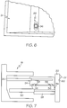
FIG. 6 is a top view of the first container ofFIGS. 2-5 with an engagement member of the second container engaging the first container; -
FIG. 7 is a sectional view ofFIG. 4 showing an engagement member engaging a slot in the first container; -
FIG. 8 is a view similar toFIG. 5 with the door in an open position and the first container in a position inside the compartment; -
FIG. 9 is a view similar toFIG. 5 with the door in an open position, the first container in a position inside the compartment, and the second container in a raised position; -
FIG. 10 is a partial view ofFIG. 1 that includes a second preferred embodiment of the subject invention with the first container in an unlatched position; -
FIG. 11 is a view similar toFIG. 10 with the first container in a latched position; -
FIG. 12 is a view similar toFIG. 11 with the door in an open position; and -
FIG. 13 is a view similar toFIG. 12 with the door in an open position and the first container located in the compartment. - Turning to the shown example of
FIG. 1 , an example storage compartment in a refrigerator-freezer 10 is provided. It is appreciated that other sizes, styles, and configurations of a refrigerator-freezer 10 are contemplated for use with the subject invention. The refrigerator-freezer 10 in this example includes anupper compartment 12 and alower compartment 18. Theupper compartment 12, which in one example can be a refrigerator compartment, includes anupper compartment door 14 and an uppercompartment door handle 16. Thelower compartment 18, which in one example can be a freezer compartment, includes alower compartment door 20 and a lowercompartment door handle 22. The lowercompartment door handle 22 is shaped for a user of the appliance to pull thedoor 20 away from the refrigerator-freezer 10. Other shapes can be used for the lowercompartment door handle 22, as well as the uppercompartment door handle 16. Theupper compartment door 14 and thelower compartment door 20 can be doors that are attached by hinges in other examples. The refrigerator-freezer 10 can also include aselection device 60. In the example ofFIG. 1 , theselection device 60 is located on theupper compartment door 14. - In the examples of
FIGS. 2-13 , thelower compartment 18 ofFIG. 1 is shown. A first embodiment is shown inFIGS. 2-9 and a second preferred embodiment is shown inFIGS. 10-13 . It is appreciated that the storage compartment apparatus of either example can be used in any compartment located in a refrigerator. Thus, for example, either example can be used in theupper compartment 12 or thelower compartment 18 of the refrigerator-freezer. Furthermore, any of the examples can be used in appliances with side-by-side compartments, or other configurations. - In the first example, the
lower compartment 18 inFIG. 2 includes afirst container 24 and asecond container 28 located within the compartment. Thefirst container 24 is an upper container and thesecond container 28 is a lower container, meaning that thesecond container 28 is located below thefirst container 24. InFIG. 2 , thesecond container 28 is in an original resting position. - The
first container 24 is configured to be movable in a first direction. The first direction is a horizontal direction. Thesecond container 28 is configured to be moveable in the first direction and configured to be moveable in a second direction. In the example ofFIG. 2 , the first direction that thefirst container 24 and thesecond container 28 are moveable in is horizontal, as seen when comparingFIG. 2 andFIG. 5 as thefirst container 24 and thesecond container 28 are moved horizontally out of thelower compartment 18. The second direction that thesecond container 28 can be moveable in is vertical, as seen when comparingFIG. 2 and FIG. 3 when thesecond container 28 moves vertically into engagement with thefirst container 24. - As seen in
FIG. 2 , thefirst container 24 can be operably connected to a first set ofrails 26, such as a set of slide rails. Thefirst container 24 in this example is movable in the first direction along the first set ofrails 26. The first set ofrails 26 are connected to the sidewalls of thelower compartment 18. Thesecond container 28 is movable in the first direction along a second set ofrails 30, such as a set of slide rails. The second set ofrails 30 can also be connected to the sidewalls of thelower compartment 18. In the example ofFIG. 2 , the first set ofrails 26 and the second set ofrails 30 allow horizontal movement of thefirst container 24 and thesecond container 28. - The
lower compartment door 20, seen inFIG. 2 , is configured to provide access to at least one of thefirst container 24 and thesecond container 28 of thelower compartment 18 when thelower compartment door 20 is in an open position (FIGS. 4, 5 ,7-9 ). Thelower compartment door 20 is also configured to inhibit access to thefirst container 24, thesecond container 28, and thelower compartment 18 when thelower compartment door 20 is in a closed position (FIGS. 2-3 ). When thelower compartment door 20 is in the closed position, this inhibits access to the containers and the compartment as the containers and the compartment cannot be physically accessed by a user. Thelower compartment door 20 can be movable in the first direction when moving from the closed position to the open position. The first direction of movement for thecompartment door 20 is a horizontal direction. Thesecond container 28 can be integrally formed with thelower compartment door 20. For example, one of the walls of thesecond container 28 can be the inner surface of thelower compartment door 20. Alternatively, thesecond container 28 can be operably connected to thedoor 20 for thesecond container 28 to move in the first direction along with thedoor 20. Thesecond container 28 can be operably connected to the door by the use of at least one attachment member. In the example ofFIG. 2 , afirst attachment member 32 is visible. InFIG. 4 , asecond attachment member 34 is visible and can also be provided, while thefirst attachment member 32 is still present but is located behind the second set ofrails 30 in this view. Thefirst attachment member 32 and thesecond attachment member 34 are used to connect thesecond container 28 to thedoor 20. Thesecond container 28 is operably connected to thedoor 20 for thesecond container 28 to move in the first direction, such as horizontally, along with thedoor 20. - In the example of
FIG. 2 , a selection of either thefirst container 24 or thesecond container 28 while thedoor 20 is in the closed position can be made where the selected container is presented in an accessible position. The accessible position of a container is a position where the user can physically move or remove items from the container, as the container is at least partially moved outwards from its compartment, and the door is in an open position. One example of an accessible position for thefirst container 24 is shown inFIG. 4 and FIG. 5 . One example of an accessible position for thesecond container 28 is shown inFIG. 8 and FIG. 9 . The selection of either container can be made while thedoor 20 is in the closed position. Theselection device 60 is configured for inputting a selection of either thefirst container 24 or thesecond container 28 to present the selected container in an accessible position. In the example ofFIGS. 2-13 , theselection device 60 is located on thelower compartment door 20. In other examples, theselection device 60 can be in other locations and additional containers can also be provided in other examples. - The
selection device 60 can be located on any portion of the appliance. Theselection device 60 can be located on theupper compartment door 14, as seen inFIG. 1 , or thelower compartment door 20, as seen inFIGS. 2-13 . Theselection device 60 can include a control panel that can be located on any portion of the refrigerator-freezer 10. In one example, theselection device 60 can be placed upon an exterior portion of a refrigerator to provide improved accessibility of theselection device 60. Theselection device 60 can also be a button, a lever, a mechanical switch, or other structure that can be selectively activated. The selection of a container can be inputted to the refrigerator-freezer 10 through the button, the lever, or the mechanical switch being placed into a position corresponding to a specific container being presented in an accessible position. - Once the selection of a container is inputted to the refrigerator through the
selection device 60, theselection device 60 can trigger an automatic movement of thelower compartment door 20 to an open position in one example through the control of a motor to open and close thelower compartment door 20. Upon the door reaching the open position, either by automatic or manual opening of the door, a selected container (e.g.first container 24 or second container 28) will be presented automatically to the user in an accessible position. In the examples shown, thelower compartment door 20 is pulled outwards with the selected container in an accessible position. In other examples, a door may open in other manners, such as a door connected on a hinge, where the selected container can be automatically moved out of thelower compartment 18 of the appliance automatically upon the door being opened. - In the example of
FIG. 2 , thesecond container 28 is configured to be moved with thelower compartment door 20. If thefirst container 24 is the selection in this example, thesecond container 28 can move in a second raised direction into engagement with thefirst container 24, as shown inFIG. 3 . In the example ofFIG. 3 , thesecond container 28 is movable from the original resting position ofFIG. 2 , to a raised position ofFIG. 3 . Thesecond container 28 is placed in engagement with thefirst container 24 when thesecond container 28 reaches the raised position ofFIG. 3 . In the example ofFIG. 2 and FIG. 3 , at least oneengagement member 36 is provided, located on the second container. Thesecond container 28 is placed in engagement with thefirst container 24 while thedoor 20 is in the closed position. Theengagement member 36 selectively engages thefirst container 24 to pull thefirst container 24 out of thelower compartment 18 to place thefirst container 24 in an accessible position upon thelower compartment door 20 being placed in the open position. Theengagement member 36 of thesecond container 28 engages thefirst container 24 when thefirst container 24 is the selection. Thesecond container 28 automatically engage theengagement member 36 with thefirst container 24 upon the selection of thefirst container 24 at theselection device 60. The distance that thesecond container 28 travels in the second direction can be controlled by a variety of methods such as by providing a limit switch, timing the movement, or providing motor encoder feedback. - The
second container 28 can be moved in the second direction, betweenFIG. 2 and FIG. 3 through the use of alifting device 40 which can be automatically activated upon the selection of a container at theselection device 60. In this example, when thesecond container 28 is selected, thedoor 20 can move automatically to the open position and thelifting device 40 can then move thesecond container 28 along a second direction which in this example is a vertical direction. The liftingdevice 40 can also move thesecond container 28 in a second direction. The liftingdevice 40 can include a track to move eachattachment member door 20. The liftingdevice 40 can include a motor configured to move at least oneattachment member second container 28 to thedoor 20. It is appreciated that thesame lifting device 40 can be used in any of the figures, but it is shown inFIGS. 3-5 for example purposes. The liftingdevice 40 inFIG. 3 shows one range of motion for thesecond container 28, though it is appreciated that thelifting device 40 can also be capable of moving thesecond container 28 along the entire length of thelower compartment door 20. - The
door 20 is movable in the first direction from the closed position ofFIG. 3 to the open position ofFIG. 4 . In this example, the first direction is a direction of horizontal travel, though in other examples, thedoor 20 can be operated in various directions. Thesecond container 28 is movable outside of thelower compartment 18 due to thesecond container 28 being operably connected to the door. In this example, theengagement members 36 of thesecond container 28 engage thefirst container 24 to cause thefirst container 24 to move outside of thelower compartment 18 along with thesecond container 28 that is operably connected to thedoor 20. Thus, thefirst container 24 and thesecond container 28 are movable with thedoor 20 upon moving thedoor 20 into the open position. - In a non-claimed embodiment, the
second container 28 can be movable in the second direction from the raised position ofFIG. 4 to return to the original resting position upon thedoor 20 reaching the open position, as seen inFIG. 5 . InFIG. 5 , thesecond container 28 is lowered and moved out of engagement from thefirst container 24. The movement of thesecond container 28 allows a user to manually move thefirst container 24, as desired, in the first direction when thedoor 20 is in the open position.FIG. 8 shows an example of when thefirst container 24 is moved back into the lower compartment. Movement along a reverse first direction allows thefirst container 24 to return to its original position inside thelower compartment 18. Thesecond container 28 can be movable in the second direction automatically upon thedoor 20 reaching the open position. - In the example shown, the
engagement member 36 is a curved locking nub, though other shapes and configurations can be provided. In this example, eachengagement member 36 engages aslot 38 in thefirst container 24, as seen inFIGS. 6-7 . A top view of thefirst container 24 with theengagement member 36 of thesecond container 28 engaging thefirst container 24 is shown inFIG. 6 . This top view shows an example of when theengagement member 36 engages the at least oneslot 38 in thefirst container 24. The at least oneslot 38 is configured to mate with eachcorresponding engagement member 36. This example shows that theengagement member 36 protrudes through theslot 38. Theslot 38 can have a size that is relatively larger than theengagement member 36. As thesecond container 28 begins to move, the ends of theslot 38 provide a point of contact between theengagement member 36 and thefirst container 24. The point of contact allows movement of thesecond container 28, such as by the door, to be translated to thefirst container 24. Thus, theengagement member 36 can pull or move thefirst container 24. Only oneengagement member 36 needs to be provided, or alternatively,multiple engagement members 36 can be used with multiplecorresponding slots 38. In further examples, the slot and the engagement members can have various shapes. In the example ofFIG. 6 , theslot 38 provides an opening in the bottom floor of thefirst container 24. It is appreciated that in other examples, the slot is only accessible from one side such that thefirst container 24 has a continuously solid bottom floor. In examples where thefirst container 24 and thesecond container 28 are located side-by-side or in other orientations, the engagement member and/or the slot can be located on any sidewall of the container. - A side view of the
engagement member 36 of thesecond container 28 engaging thefirst container 24 is shown inFIG. 7 . This view is similar toFIG. 4 , except that it is a sectional view showing theengagement member 36 engaging theslots 38 of thefirst container 24. This view shows an example arrangement of theengagement member 36 and how it engages theslots 38 of thefirst container 24. As in this example, theslots 38 can provide additional space for varyingsized engagement members 36. Theengagement members 36 are in contact with the edge of theslots 38 so as to translate movement of thesecond container 28 to thefirst container 24. - If the
second container 28 is the selected container when thedoor 20 is in the closed position ofFIG. 2 , only thesecond container 28 is moved outwards from thelower compartment 18 of the refrigerator-freezer 10, as seen inFIG. 8 . As one alternative, the user can still have thesecond container 28 placed in a raised position once thesecond container 28 moves out of the compartment, as shown inFIG. 9 . This can provide improved accessibility for thesecond container 28. In other examples, thesecond container 28 can automatically be placed in the raised position ofFIG. 9 upon thesecond container 28 being the selected container. In other examples, thesecond container 28 can be moved partially in the second direction while thedoor 20 is in the closed position so that thesecond container 28 is in the raised position ofFIG. 9 as soon as thedoor 20 is placed in the open position. A partial movement in the second direction for thesecond container 28 can improve the accessibility of thesecond container 28 as a user does not have to bend down as far to reach thesecond container 28. Thedoor 20 can be opened automatically or manually. In another example, thesecond container 28 can automatically be placed in the raised position ofFIG. 9 upon thefirst container 24 being moved or manually moved inside thelower compartment 18. -
FIGS. 10-13 show a second preferred embodiment of the subject invention. In the second embodiment, thelower compartment 18 ofFIG. 1 inFIG. 10 is shown. Thelower compartment 18 includes afirst container 24 and asecond container 28 located within the compartment. Thefirst container 24 is an upper container and thesecond container 28 is a lower container, meaning that thesecond container 28 is located below thefirst container 24. InFIG. 10 , thesecond container 28 is in an original resting position. - The
first container 24 is configured to be movable in a first direction. The first direction is a horizontal direction. Thesecond container 28 is configured to be moveable in the first direction but is also configured to be moveable in a second direction. In the example ofFIG. 10 , the first direction that thefirst container 24 and thesecond container 28 are moveable in is horizontal, as seen when comparingFIG. 10 andFIG. 12 as thefirst container 24 and thesecond container 28 are moved horizontally out of thelower compartment 18. The second direction that thesecond container 28 can be moveable in is vertical, which would be similar to the first example ofFIGS. 2-5 . - As seen in
FIG. 10 , thefirst container 24 can be operably connected to a first set ofrails 26, such as a set of slide rails. Thefirst container 24 in this example is movable in the first direction along the first set ofrails 26. The first set ofrails 26 are connected to the sidewalls of thelower compartment 18. Thesecond container 28 is movable in the first direction along a second set ofrails 30, such as a set of slide rails. The second set ofrails 30 can also be connected to the sidewalls of thelower compartment 18. In the example ofFIG. 10 , the first set ofrails 26 and the second set ofrails 30 allow horizontal movement of thefirst container 24 and thesecond container 28. In other examples, the first set ofrails 26 and the second set ofrails 30 can be oriented in varying directions to allow varying directional movements. - The
lower compartment door 20 of thelower compartment 18, seen inFIG. 10 , is configured to provide access to at least one of thefirst container 24 and thesecond container 28 when thelower compartment door 20 is in an open position (FIGS. 12-13 ). Thelower compartment door 20 is also configured to inhibit access to thefirst container 24, thesecond container 28 and thelower compartment 18 in a closed position (FIGS. 10-11 ). When thelower compartment door 20 is in the closed position, this inhibits access to the containers and the compartment as the containers and the compartment cannot be physically accessed by a user. Thelower compartment door 20 can be movable in the first direction when moving from the closed position to the open position. The first direction of movement for thecompartment door 20 is a horizontal direction. Thesecond container 28 can be integrally formed with thelower compartment door 20. For example, one of the walls of thesecond container 28 can be the inner surface of thelower compartment door 20. Alternatively, thesecond container 28 can be operably connected to thedoor 20 for thesecond container 28 to move in the first direction along with thedoor 20. Thesecond container 28 can be operably connected to the door by the use of at least one attachment member. In the example ofFIG. 10 , afirst attachment member 32 is visible. Thefirst attachment member 32 is used to connect thesecond container 28 to thedoor 20. It is appreciated that additional attachment members can also be provided. Thesecond container 28 is connected to thedoor 20 for thesecond container 28 to move in the first direction, such as horizontally, along with thedoor 20. - In the example of
FIG. 10 , a selection of either thefirst container 24 or thesecond container 28 while thedoor 20 is in the closed position can be made where the selected container is presented in an accessible position. The accessible position of a container is a position where the user can physically move or remove items from the container, as the container is at least partially moved outwards from its compartment, and the door is in an open position. One example of an accessible position for thefirst container 24 is shown inFIG. 12 . One example of an accessible position for thesecond container 28 is shown inFIG. 13 . The selection of either container can be made while thedoor 20 is in the closed position. Theselection device 60 is configured for inputting a selection of either thefirst container 24 or thesecond container 28 to present the selected container in an accessible position. For example, while thedoor 20 is in the closed position, a user can input a selection to the refrigerator-freezer 10 as to whether thefirst container 24 or thesecond container 28 will be selected for presentation. - The
selection device 60 can be located on any portion of the refrigerator-freezer and can be formed of various structures, as already described. Theselection device 60 is configured for inputting a selection of eitherfirst container 24 or thesecond container 28 to present the selected container in an accessible position. It is appreciated that in the example shown, the selected container is either thefirst container 24 or thesecond container 28, but in other examples, additional containers can be used. - Once the selection of a container is inputted to the refrigerator through the
selection device 60, theselection device 60 can trigger an automatic movement of thelower compartment door 20 to an open position in one example through the control of a motor to open and close thelower compartment door 20. Upon the door reaching the open position, either by automatic or manual opening of the door, a selected container (e.g.first container 24 or second container 28) will be presented automatically to the user in an accessible position. In the examples shown, thelower compartment door 20 is pulled outwards with the selected container in an accessible position. In other examples, a door may open in other manners, such as a door connected on a hinge, where the selected container can be automatically moved out of thelower compartment 18 of the appliance automatically upon the door being placed in an open position. - According to a preferred embodiment, the
selection device 60 can include alatch 50 located on thefirst container 24. If thefirst container 24 is selected for presentation in the example ofFIG. 10 , thelatch 50 can be activated by theselection device 60 to cause thefirst container 24 to be movable with thedoor 20. Theselection device 60 can further include a selectively activatedlatch portion 52 that is located on thelower compartment door 20. Activation of the selectively activatedlatch portion 52 causes the selectively activatedlatch portion 52 to engage thelatch 50 and secures thefirst container 24 to thedoor 20. Activation of the selectively activatedlatch portion 52 also causes thefirst container 24 to be movable with thedoor 20 when thedoor 20 moves from the closed position to the open position. In one example, the selectively activatedlatch portion 52 includes a corresponding magnet located within thedoor 20. Activation of the magnet causes thelatch 50 to be connected to the selectively activatedlatch portion 52. In other examples of thelatch 50, thelatch 50 is a mechanical latch where activation of thelatch 50 results in a mechanical interlocking between thelatch 50 and the selectively activatedlatch portion 52. It is appreciated that the locations of thelatch 50 and the selectively activatedlatch portion 52 can be varied while still enabling a selective presentation of thefirst container 24 or thesecond container 28. In another example of thelatch 50, thelatch 50 can include a solenoid actuated structure. - The
first container 24 is in an example unlatched position inFIG. 10 . It is appreciated that other positions of thefirst container 24 are also appreciated. Activation of the selectively activatedlatch portion 52 causes the first container to move into a latched position, seen inFIG. 11 andFIG. 12 .FIG. 11 shows the example ofFIG. 10 with the selectively activatedlatch portion 52 activated.FIG. 12 shows the example ofFIG. 11 with thedoor 20 moved into an open position while the selectively activatedlatch portion 52 is still activated to pull thefirst container 24 out of thelower compartment 18. - If the
second container 28 is selected for presentation, only thesecond container 28 is moved outwards from thelower compartment 18 of the refrigerator-freezer 10, as seen inFIG. 13. FIG. 13 shows the example ofFIG. 10 when thelatch 50 is not selected to be activated by the user. In other examples, a plurality of bins or containers can be provided and a user can provide input to the appliance on theselection device 60, such as a control panel, to selectively determine exactly which containers will be presented in an accessible position to the user through the use of a plurality of latches. - According to a preferred embodiment, the user can still have the
second container 28 move in a second direction and placed in a raised position inFIG. 13 through the addition of alifting device 40, as seen in the first example inFIGS. 3-5 . In this example, the liftingdevice 40 moves thesecond container 28 along a second direction, which in this example is a vertical direction. This can provide improved accessibility to thesecond container 28 when thesecond container 28 is selected for presentation. As another example, if thesecond container 28 is the selected container, thesecond container 28 can automatically be placed in the raised position once thedoor 20 is opened. Thedoor 20 can be opened automatically or manually. In other examples, thesecond container 28 can be moved partially in the second direction while thedoor 20 is in the closed position so that thesecond container 28 is in the raised position as soon as thedoor 20 is placed in the open position. In another example, thesecond container 28 can automatically be placed in the raised position ofFIG. 9 upon thefirst container 24 being moved or manually moved inside thelower compartment 18. - The subject invention also includes examples of a method of selecting one container in a compartment of an appliance, such as a refrigerator-
freezer 10, and automatically moving the selected container to an accessible position, such as a refrigerator-freezer 10. The method includes the step of providing a selection device to input a selection of either afirst container 24 or asecond container 28 while adoor 20 is in a closed position, as seen inFIG. 2 orFIG. 10 . Another step in the example method is to move thedoor 20 from the closed position to an open position where the selected container is in the accessible position when the door reaches the open position. Thedoor 20 can be opened automatically or manually. - If the
first container 24 is selected for presentation, the method can further include the step of moving thefirst container 24 and thesecond container 28 together along with thedoor 20 in a first direction from the closed position of the door 20 (see example ofFIG. 2 orFIG. 10 ) to an open position of the door 20 (see example ofFIG. 4 or FIG. 5 orFIG. 12 ) when thefirst container 24 is selected for presentation. This example method can further include the step of manually moving thefirst container 24 in the first direction into thelower compartment 18 when thedoor 20 is moved to the open position (see example ofFIG. 5 andFIG. 8 or example ofFIG. 12 and FIG. 13 ). The method further includes the step of moving thesecond container 28 in a second direction, such as a vertical direction, from an original resting position to a raised position, as seen inFIG. 3 . This movement can occur while the door is in the closed position. In another example method, an additional step can be included. Upon the door reaching the open position when thefirst container 24 is selected for presentation, thesecond container 28 can still be moved from the raised position to the original resting position, as seen inFIG. 5 . - If the
second container 28 is selected, one example includes only thesecond container 28 moving outwards from thelower compartment 18 of the refrigerator-freezer 10, as seen in the example ofFIG. 8 orFIG. 13 . In another example method, if thesecond container 28 is selected for presentation, an additional step can include moving thesecond container 28 from the original resting position to the raised position while the door is in the open position, as seen inFIG. 9 . This step can improve accessibility of thesecond container 28. - Each of the example methods of selecting one container to be moved to an accessible position from a compartment of an appliance can involve the appliance automatically performing the method upon a selection of either a first container or a second container. For example, if a user selects the first container while the door is in the closed position, the appliance can automatically move the second container in a second direction to engage the two containers before the door is moved into an open position. In another example, a latch is automatically activated to pull a first container along with the door. Thus, not only can the door move automatically from a closed position to an open position, but the method can involve the containers moving automatically and/or various latches being activated to present the selected container in an accessible position.
- The invention has been described with reference to the examples described above. Modifications and alterations will occur to others upon a reading and understanding of this specification. Examples incorporating one or more aspects of the invention are intended to include all such modifications and alterations insofar as they come within the scope of the appended claims.
Claims (16)
- A refrigerator (10) comprising:a compartment (18);a first container (24) located in the compartment (18) and configured to be movable in a first direction;a second container (28) located in the compartment (18) and configured to be movable in the first direction;a door (20) operably connected to the second container (28) and configured to provide access to at least one of the first container (24) and the second container (28) of the compartment (18) when the door (20) is moved to an open position; wherein the door (20) is configured to inhibit access to the compartment (18) when the door (20) is moved to a closed position; anda selection device (60) located on the refrigerator (10) wherein the selection device (60) is configured to input a selection of either the first container (24) or the second container (28);wherein the selected container is presented in an accessible position when the door (20) is moved to the open position, the accessible position defined as the selected container extended outward from the compartment (18),
characterized in thatthe second container (28) is configured to be movable in the first direction and a second direction from an original resting position to a raised position, wherein when the first container (24) is the selected container, the selection device (60) is configured to trigger an automatic movement of the second container (28) to the raised position and in engagement with the first container (24) such that the first container (24) is in the accessible position when the door (20) is moved to the open position. - The refrigerator (10) according to claim 1, further comprising:
at least one engagement member (36) located on the second container (28) that is configured for selectively engaging the first container (24) to pull the first container (24) out of the compartment to move the first container (24) into the accessible position. - The refrigerator (10) according to claim 1 or 2, wherein:the door (20) is movable in the first direction when moving from the closed position to the open position; andwherein the first container (24) is operably connected to a first set of rails (26) in the compartment (18) for movement in the first direction and the second container is operably connected to the door (20) for the second container (28) to move in the first direction along with the door (20).
- The refrigerator (10) according to claim 1 or 2, further comprising:
a lifting device (40) configured to move the second container (28) in the second direction. - The refrigerator (10) according to claim 1 or 4, wherein:the selection is the first container (24); andthe second container (28) is placed in engagement with the first container (24) while the door (20) is in the closed position.
- The refrigerator (10) according to claim 5, wherein:the door (20) is movable in the first direction when moving the door (20) from the closed position to the open position;the first container (24) and the second container (28) are movable with the door (20) upon moving the door (20) into the open position;the second container (28) is movable in the second direction from the raised position to return to the original resting position upon the door (20) reaching the open position; andthe first container (24) is manually movable in the first direction when the door (20) is moved to the open position and the second container (28) is in the original resting position.
- The refrigerator (10) according to claim 1, further comprising:a latch (50) operably connected to the first container (24);wherein the latch (50) is configured to be selectively activated by the selection device (60) to cause the first container (24) to also be movable with the door (20) when the door (20) moves from the closed position into the open position.
- The refrigerator (10) according to claim 7, wherein the latch (50) includes a corresponding magnet located on the door (20).
- The refrigerator (10) according to claim 2, further comprising:
at least one slot (38) located on the first container (24) and configured to mate with the at least one engagement member (36) of the second container (28). - The refrigerator (10) according to claim 1, wherein
the door (20) is movable in the first direction when moving from the closed position to the open position;
the second container (28) is movable with the door (20) upon moving the door (20) into the open position; and
the selection device (60) includes a latch (50) located on the first container (24) and the latch (50) is configured to be selectively activated to engage the door (20), wherein activation of the latch (50) causes the first container (24) to also be movable with the door (20) when the door (20) moves from the closed position into the open position. - A method of selecting one container in a compartment (18) of a refrigerator (10) according to claim 1 and automatically moving the selected container to an accessible position comprising the steps of:providing a first container (24) and a second container (28);providing a door (20) to the compartment (18) operably connected to the second container (28) and configured to provide access to the selected container in the accessible position, the accessible position defined as the selected container extend outward from the compartment (18);providing a selection device (60) to input a selection of either a first container (24) or a second container (28), wherein when the first container (24) is the selected container, the selection device (60) triggers an automatic movement of the second container (28) from an original resting position to a raised position and configured to be in the raised position and in engagement with the first container (24); andmoving the door (20) from a closed position to an open position wherein the selected container is in the accessible position when the door (20) reaches the open position, such that when the first container (24) is in the accessible position.
- The method of claim 11, further comprising the step of:
moving the first container (24) and the second container (28) together along with the door (20) in a first direction from the closed position of the door (20) to the open position of the door (20) when the first container (24) is the selected container. - The method of claim 12, further comprising the step of:
manually moving the first container (24) into the compartment when the door (20) is moved to the open position. - The method of claim 13, further comprising the step of:moving the second container (28) in a second direction from an original resting position to a raised position while the door (20) is in the closed position when the first container (24) is the selected container; andmoving the second container (28) in the second direction from the raised position to the original resting position upon the door (20) reaching the open position.
- The method of claim 11, further comprising the step of:
moving only the second container (28) outwards from the compartment (18) when the second container (28) is the selected container. - The method of claim 11, further comprising the step of:
moving the second container (28) from the original resting position to the raised position while the door (20) is moved to the open position when the second container (28) is the selected container.
Applications Claiming Priority (3)
| Application Number | Priority Date | Filing Date | Title |
|---|---|---|---|
| US39406209A | 2009-02-27 | 2009-02-27 | |
| US12/580,759 US8220887B2 (en) | 2009-02-27 | 2009-10-16 | Selectable presentation of dual-bin system |
| PCT/US2010/024703 WO2010099037A2 (en) | 2009-02-27 | 2010-02-19 | Selectable presentation of dual-bin system |
Publications (2)
| Publication Number | Publication Date |
|---|---|
| EP2401568A2 EP2401568A2 (en) | 2012-01-04 |
| EP2401568B1 true EP2401568B1 (en) | 2020-01-15 |
Family
ID=42666156
Family Applications (1)
| Application Number | Title | Priority Date | Filing Date |
|---|---|---|---|
| EP10705720.0A Active EP2401568B1 (en) | 2009-02-27 | 2010-02-19 | Selectable presentation of dual-bin system |
Country Status (7)
| Country | Link |
|---|---|
| US (1) | US8220887B2 (en) |
| EP (1) | EP2401568B1 (en) |
| KR (1) | KR20110128900A (en) |
| CN (1) | CN102405388B (en) |
| AU (1) | AU2010218207B2 (en) |
| BR (1) | BRPI1007822B1 (en) |
| WO (1) | WO2010099037A2 (en) |
Families Citing this family (34)
| Publication number | Priority date | Publication date | Assignee | Title |
|---|---|---|---|---|
| KR101644014B1 (en) * | 2008-10-13 | 2016-07-29 | 삼성전자주식회사 | Refrigerator |
| US8162422B2 (en) * | 2009-01-15 | 2012-04-24 | Lg Electronics Inc. | Refrigerator |
| KR101787095B1 (en) * | 2009-07-07 | 2017-10-18 | 엘지전자 주식회사 | Refrigerator |
| KR20110006145A (en) | 2009-07-13 | 2011-01-20 | 삼성전자주식회사 | Refrigerator |
| KR20110010405A (en) * | 2009-07-24 | 2011-02-01 | 엘지전자 주식회사 | Refrigerator |
| US8671712B2 (en) * | 2010-03-25 | 2014-03-18 | Whirlpool Corporation | Upper freezer basket guided by lower freezer basket divider |
| JP5388952B2 (en) * | 2010-05-31 | 2014-01-15 | Toto株式会社 | Drawer interlocking device |
| JP5388951B2 (en) * | 2010-05-31 | 2014-01-15 | Toto株式会社 | Drawer interlocking device |
| ES2401653B1 (en) * | 2011-03-18 | 2014-03-21 | BSH Electrodomésticos España S.A. | Cooking product holder for a cooking appliance, cooking appliance with a corresponding cooking product holder, and procedure for moving a cooking product holder in a housing |
| JP5855544B2 (en) * | 2011-08-02 | 2016-02-09 | シャープ株式会社 | refrigerator |
| US8925346B2 (en) * | 2012-02-07 | 2015-01-06 | Thermo Fisher Scientific (Asheville) Llc | High performance freezer having cylindrical cabinet |
| CN102564024B (en) * | 2012-02-21 | 2014-02-26 | 合肥美的电冰箱有限公司 | refrigerator |
| US20130328463A1 (en) * | 2012-06-07 | 2013-12-12 | Bsh Home Appliances Corporation | Rack with protrusion device for kitchen appliance |
| US9605891B2 (en) | 2014-03-11 | 2017-03-28 | Samsung Electronics Co., Ltd. | Refrigerator |
| JP6165667B2 (en) * | 2014-04-17 | 2017-07-19 | 日立アプライアンス株式会社 | refrigerator |
| JP6165669B2 (en) * | 2014-04-17 | 2017-07-19 | 日立アプライアンス株式会社 | refrigerator |
| JP6434251B2 (en) * | 2014-08-13 | 2018-12-05 | 株式会社ノーリツ | Drawer and cabinet with the drawer |
| KR101641263B1 (en) * | 2014-12-23 | 2016-07-20 | 엘지전자 주식회사 | Refrigerator |
| DE102016120584A1 (en) * | 2016-10-27 | 2018-05-03 | Paul Hettich Gmbh & Co. Kg | Furniture and method for opening a drawer and an inner drawer |
| KR102721564B1 (en) * | 2016-12-29 | 2024-10-25 | 삼성전자주식회사 | Refrigerator |
| CN107152827A (en) * | 2017-05-19 | 2017-09-12 | 合肥华凌股份有限公司 | Refrigerating chamber and refrigerator |
| US20190032993A1 (en) * | 2017-07-31 | 2019-01-31 | Haier Us Appliance Solutions, Inc. | Refrigerator appliances including a drawer assembly |
| CN107830922A (en) * | 2017-10-12 | 2018-03-23 | 灵动科技(北京)有限公司 | Call oneself weighing method for intelligent mobile luggage case |
| JP7164355B2 (en) * | 2018-08-21 | 2022-11-01 | 東芝ライフスタイル株式会社 | refrigerator |
| CN109708418B (en) * | 2018-11-20 | 2024-11-19 | 海尔智家股份有限公司 | refrigerator |
| KR102211191B1 (en) * | 2018-12-07 | 2021-02-03 | 엘지전자 주식회사 | Refrigerator and control method thereof |
| KR102663561B1 (en) | 2018-12-28 | 2024-05-08 | 엘지전자 주식회사 | Refrigerator |
| KR102579883B1 (en) | 2018-12-28 | 2023-09-18 | 엘지전자 주식회사 | Refrigerator |
| KR102583877B1 (en) * | 2018-12-28 | 2023-10-04 | 엘지전자 주식회사 | Refrigerator |
| CN112146337B (en) | 2019-06-27 | 2021-09-21 | 青岛海尔电冰箱有限公司 | Refrigerator drawer and refrigerator |
| US10820725B1 (en) * | 2019-11-12 | 2020-11-03 | Whirlpool Corporation | Shelf and drawer assemblies for storing bottles |
| CN110916810A (en) * | 2019-12-27 | 2020-03-27 | 蒋海莹 | Medical instrument storage device convenient to take and place for general medical treatment |
| CN211823449U (en) * | 2020-01-22 | 2020-10-30 | 青岛海尔电冰箱有限公司 | refrigerator |
| US11774172B2 (en) * | 2021-06-24 | 2023-10-03 | Electrolux Home Products, Inc. | Drawer in a refrigerator door |
Family Cites Families (28)
| Publication number | Priority date | Publication date | Assignee | Title |
|---|---|---|---|---|
| US2711944A (en) * | 1949-05-21 | 1955-06-28 | George W Meek | Refrigerator drawer and latch |
| US2919691A (en) * | 1955-08-22 | 1960-01-05 | Moffats Ltd | Mechanism for adjusting the height of racks in range ovens |
| US3043290A (en) * | 1961-03-01 | 1962-07-10 | Moffats Ltd | Oven rack elevating and lowering mechanism |
| US3976000A (en) * | 1975-02-27 | 1976-08-24 | The Hoover Company | Rotatable and vertically adjustable rack |
| JP2795970B2 (en) | 1990-06-12 | 1998-09-10 | 松下冷機株式会社 | refrigerator |
| US5299863A (en) * | 1991-11-14 | 1994-04-05 | Albright Jr Harold D | Refrigerator with sliding interior frame |
| US5429043A (en) * | 1994-10-24 | 1995-07-04 | Becker; Ruby | Power operated adjustable oven rack |
| JP4045382B2 (en) | 1997-09-10 | 2008-02-13 | 株式会社デンソー | Fuel supply device |
| CA2227355C (en) * | 1998-01-19 | 2004-04-06 | Samir Atalla | Basket mounting arrangement for a refrigerator |
| US6523919B1 (en) * | 1999-07-21 | 2003-02-25 | Switchboard | Filing cabinet having vertically extensible drawers |
| GB2354061B (en) * | 1999-09-13 | 2001-08-08 | Ian David Wood | Cold-storage appliance |
| AU3833900A (en) * | 2000-03-20 | 2001-10-03 | Mo-El S.R.L. | Device and method for the preservation of foods under vacuum |
| US6467285B2 (en) * | 2000-08-23 | 2002-10-22 | University Of Virginia Patent Foundation | Automated storage and retrieval apparatus for freezers and related method thereof |
| CA2349373C (en) * | 2001-05-31 | 2007-07-24 | Camco Inc. | Two part refrigerator shelf |
| ATE479974T1 (en) * | 2001-12-26 | 2010-09-15 | Hamafteach Hamistovev Ltd | PROTECTED HOUSING |
| US6971730B2 (en) * | 2002-03-15 | 2005-12-06 | Maytag Corporation | Freezer drawer support assembly |
| KR100555826B1 (en) * | 2003-10-04 | 2006-03-03 | 엘지전자 주식회사 | Refrigerator |
| KR100690645B1 (en) * | 2004-07-15 | 2007-03-09 | 엘지전자 주식회사 | Refrigerator with basket lift |
| KR100664052B1 (en) * | 2004-08-26 | 2007-01-03 | 엘지전자 주식회사 | Refrigerator with basket lift |
| KR100700776B1 (en) * | 2005-03-02 | 2007-03-27 | 엘지전자 주식회사 | Refrigerator, door control device and door control method of refrigerator |
| KR100700777B1 (en) * | 2005-03-02 | 2007-03-27 | 엘지전자 주식회사 | Refrigerator and basket drive of refrigerator |
| KR100662406B1 (en) * | 2005-04-19 | 2007-01-02 | 엘지전자 주식회사 | Refrigerator |
| US7406833B2 (en) * | 2005-05-27 | 2008-08-05 | Whirlpool Corporation | Refrigerator storage system |
| US20060290248A1 (en) * | 2005-06-27 | 2006-12-28 | Joe Chandler | Table with electric hidden storage |
| US7744173B2 (en) * | 2006-04-25 | 2010-06-29 | Whirlpool Corporation | Ice bucket retainer for refrigerator |
| US7628461B2 (en) * | 2006-07-20 | 2009-12-08 | Maytag Corporation | Bottom mount refrigerator having an elevating freezer basket |
| US8459759B2 (en) | 2007-03-14 | 2013-06-11 | Lg Electronics Inc. | Refrigerator and drawer opening/closing apparatus for the same |
| KR20080101335A (en) | 2007-05-17 | 2008-11-21 | 삼성전자주식회사 | Refrigerator |
-
2009
- 2009-10-16 US US12/580,759 patent/US8220887B2/en not_active Expired - Fee Related
-
2010
- 2010-02-19 CN CN201080017404.1A patent/CN102405388B/en not_active Expired - Fee Related
- 2010-02-19 KR KR1020117022653A patent/KR20110128900A/en not_active Ceased
- 2010-02-19 EP EP10705720.0A patent/EP2401568B1/en active Active
- 2010-02-19 AU AU2010218207A patent/AU2010218207B2/en not_active Ceased
- 2010-02-19 BR BRPI1007822-3A patent/BRPI1007822B1/en not_active IP Right Cessation
- 2010-02-19 WO PCT/US2010/024703 patent/WO2010099037A2/en not_active Ceased
Non-Patent Citations (1)
| Title |
|---|
| None * |
Also Published As
| Publication number | Publication date |
|---|---|
| KR20110128900A (en) | 2011-11-30 |
| WO2010099037A3 (en) | 2010-11-04 |
| CN102405388A (en) | 2012-04-04 |
| CN102405388B (en) | 2014-07-16 |
| AU2010218207B2 (en) | 2013-09-26 |
| BRPI1007822A2 (en) | 2017-03-01 |
| WO2010099037A2 (en) | 2010-09-02 |
| AU2010218207A1 (en) | 2011-09-22 |
| BRPI1007822B1 (en) | 2020-08-18 |
| EP2401568A2 (en) | 2012-01-04 |
| US20100219730A1 (en) | 2010-09-02 |
| US8220887B2 (en) | 2012-07-17 |
Similar Documents
| Publication | Publication Date | Title |
|---|---|---|
| US8220887B2 (en) | Selectable presentation of dual-bin system | |
| US11486634B2 (en) | Refrigerator | |
| US11346598B2 (en) | Refrigerator | |
| KR20230151968A (en) | A refrigerator | |
| US7628461B2 (en) | Bottom mount refrigerator having an elevating freezer basket | |
| US9869112B2 (en) | Refrigerator | |
| KR102580773B1 (en) | A refrigerator | |
| EP3764042A1 (en) | Refrigerator | |
| US11592233B2 (en) | Refrigerator | |
| JP2009228948A (en) | Refrigerator | |
| EP3764039B1 (en) | Refrigerator | |
| KR20220162109A (en) | Refrigerator | |
| JP6360688B2 (en) | refrigerator | |
| JP2020193755A (en) | refrigerator | |
| KR20180028776A (en) | Refrigerator | |
| US20250172331A1 (en) | Refrigerator | |
| KR101803625B1 (en) | A refrigerator | |
| KR20260000237A (en) | Refrigerator | |
| KR200463488Y1 (en) | Refrigerator | |
| KR20150017934A (en) | Refrigerator |
Legal Events
| Date | Code | Title | Description |
|---|---|---|---|
| PUAI | Public reference made under article 153(3) epc to a published international application that has entered the european phase |
Free format text: ORIGINAL CODE: 0009012 |
|
| 17P | Request for examination filed |
Effective date: 20110926 |
|
| AK | Designated contracting states |
Kind code of ref document: A2 Designated state(s): AT BE BG CH CY CZ DE DK EE ES FI FR GB GR HR HU IE IS IT LI LT LU LV MC MK MT NL NO PL PT RO SE SI SK SM TR |
|
| DAX | Request for extension of the european patent (deleted) | ||
| RAP1 | Party data changed (applicant data changed or rights of an application transferred) |
Owner name: ELECTROLUX HOME PRODUCTS, INC. |
|
| STAA | Information on the status of an ep patent application or granted ep patent |
Free format text: STATUS: EXAMINATION IS IN PROGRESS |
|
| 17Q | First examination report despatched |
Effective date: 20180122 |
|
| RIC1 | Information provided on ipc code assigned before grant |
Ipc: F25D 23/02 20060101ALN20190618BHEP Ipc: A47B 67/04 20060101ALI20190618BHEP Ipc: F25D 25/04 20060101ALN20190618BHEP Ipc: A47B 88/70 20170101ALI20190618BHEP Ipc: F25D 25/02 20060101AFI20190618BHEP |
|
| GRAP | Despatch of communication of intention to grant a patent |
Free format text: ORIGINAL CODE: EPIDOSNIGR1 |
|
| STAA | Information on the status of an ep patent application or granted ep patent |
Free format text: STATUS: GRANT OF PATENT IS INTENDED |
|
| RIC1 | Information provided on ipc code assigned before grant |
Ipc: F25D 25/04 20060101ALN20190701BHEP Ipc: F25D 25/02 20060101AFI20190701BHEP Ipc: A47B 67/04 20060101ALI20190701BHEP Ipc: F25D 23/02 20060101ALN20190701BHEP Ipc: A47B 88/70 20170101ALI20190701BHEP |
|
| INTG | Intention to grant announced |
Effective date: 20190726 |
|
| GRAS | Grant fee paid |
Free format text: ORIGINAL CODE: EPIDOSNIGR3 |
|
| GRAA | (expected) grant |
Free format text: ORIGINAL CODE: 0009210 |
|
| STAA | Information on the status of an ep patent application or granted ep patent |
Free format text: STATUS: THE PATENT HAS BEEN GRANTED |
|
| AK | Designated contracting states |
Kind code of ref document: B1 Designated state(s): AT BE BG CH CY CZ DE DK EE ES FI FR GB GR HR HU IE IS IT LI LT LU LV MC MK MT NL NO PL PT RO SE SI SK SM TR |
|
| REG | Reference to a national code |
Ref country code: CH Ref legal event code: EP Ref country code: GB Ref legal event code: FG4D |
|
| REG | Reference to a national code |
Ref country code: IE Ref legal event code: FG4D |
|
| REG | Reference to a national code |
Ref country code: DE Ref legal event code: R096 Ref document number: 602010062791 Country of ref document: DE |
|
| REG | Reference to a national code |
Ref country code: AT Ref legal event code: REF Ref document number: 1225509 Country of ref document: AT Kind code of ref document: T Effective date: 20200215 |
|
| REG | Reference to a national code |
Ref country code: NL Ref legal event code: MP Effective date: 20200115 |
|
| REG | Reference to a national code |
Ref country code: LT Ref legal event code: MG4D |
|
| PG25 | Lapsed in a contracting state [announced via postgrant information from national office to epo] |
Ref country code: NL Free format text: LAPSE BECAUSE OF FAILURE TO SUBMIT A TRANSLATION OF THE DESCRIPTION OR TO PAY THE FEE WITHIN THE PRESCRIBED TIME-LIMIT Effective date: 20200115 Ref country code: PT Free format text: LAPSE BECAUSE OF FAILURE TO SUBMIT A TRANSLATION OF THE DESCRIPTION OR TO PAY THE FEE WITHIN THE PRESCRIBED TIME-LIMIT Effective date: 20200607 Ref country code: FI Free format text: LAPSE BECAUSE OF FAILURE TO SUBMIT A TRANSLATION OF THE DESCRIPTION OR TO PAY THE FEE WITHIN THE PRESCRIBED TIME-LIMIT Effective date: 20200115 Ref country code: NO Free format text: LAPSE BECAUSE OF FAILURE TO SUBMIT A TRANSLATION OF THE DESCRIPTION OR TO PAY THE FEE WITHIN THE PRESCRIBED TIME-LIMIT Effective date: 20200415 |
|
| PG25 | Lapsed in a contracting state [announced via postgrant information from national office to epo] |
Ref country code: IS Free format text: LAPSE BECAUSE OF FAILURE TO SUBMIT A TRANSLATION OF THE DESCRIPTION OR TO PAY THE FEE WITHIN THE PRESCRIBED TIME-LIMIT Effective date: 20200515 Ref country code: BG Free format text: LAPSE BECAUSE OF FAILURE TO SUBMIT A TRANSLATION OF THE DESCRIPTION OR TO PAY THE FEE WITHIN THE PRESCRIBED TIME-LIMIT Effective date: 20200415 Ref country code: HR Free format text: LAPSE BECAUSE OF FAILURE TO SUBMIT A TRANSLATION OF THE DESCRIPTION OR TO PAY THE FEE WITHIN THE PRESCRIBED TIME-LIMIT Effective date: 20200115 Ref country code: SE Free format text: LAPSE BECAUSE OF FAILURE TO SUBMIT A TRANSLATION OF THE DESCRIPTION OR TO PAY THE FEE WITHIN THE PRESCRIBED TIME-LIMIT Effective date: 20200115 Ref country code: LV Free format text: LAPSE BECAUSE OF FAILURE TO SUBMIT A TRANSLATION OF THE DESCRIPTION OR TO PAY THE FEE WITHIN THE PRESCRIBED TIME-LIMIT Effective date: 20200115 Ref country code: GR Free format text: LAPSE BECAUSE OF FAILURE TO SUBMIT A TRANSLATION OF THE DESCRIPTION OR TO PAY THE FEE WITHIN THE PRESCRIBED TIME-LIMIT Effective date: 20200416 |
|
| REG | Reference to a national code |
Ref country code: CH Ref legal event code: PL |
|
| REG | Reference to a national code |
Ref country code: DE Ref legal event code: R097 Ref document number: 602010062791 Country of ref document: DE |
|
| REG | Reference to a national code |
Ref country code: BE Ref legal event code: MM Effective date: 20200229 |
|
| PG25 | Lapsed in a contracting state [announced via postgrant information from national office to epo] |
Ref country code: DK Free format text: LAPSE BECAUSE OF FAILURE TO SUBMIT A TRANSLATION OF THE DESCRIPTION OR TO PAY THE FEE WITHIN THE PRESCRIBED TIME-LIMIT Effective date: 20200115 Ref country code: EE Free format text: LAPSE BECAUSE OF FAILURE TO SUBMIT A TRANSLATION OF THE DESCRIPTION OR TO PAY THE FEE WITHIN THE PRESCRIBED TIME-LIMIT Effective date: 20200115 Ref country code: MC Free format text: LAPSE BECAUSE OF FAILURE TO SUBMIT A TRANSLATION OF THE DESCRIPTION OR TO PAY THE FEE WITHIN THE PRESCRIBED TIME-LIMIT Effective date: 20200115 Ref country code: SM Free format text: LAPSE BECAUSE OF FAILURE TO SUBMIT A TRANSLATION OF THE DESCRIPTION OR TO PAY THE FEE WITHIN THE PRESCRIBED TIME-LIMIT Effective date: 20200115 Ref country code: RO Free format text: LAPSE BECAUSE OF FAILURE TO SUBMIT A TRANSLATION OF THE DESCRIPTION OR TO PAY THE FEE WITHIN THE PRESCRIBED TIME-LIMIT Effective date: 20200115 Ref country code: CZ Free format text: LAPSE BECAUSE OF FAILURE TO SUBMIT A TRANSLATION OF THE DESCRIPTION OR TO PAY THE FEE WITHIN THE PRESCRIBED TIME-LIMIT Effective date: 20200115 Ref country code: SK Free format text: LAPSE BECAUSE OF FAILURE TO SUBMIT A TRANSLATION OF THE DESCRIPTION OR TO PAY THE FEE WITHIN THE PRESCRIBED TIME-LIMIT Effective date: 20200115 Ref country code: LU Free format text: LAPSE BECAUSE OF NON-PAYMENT OF DUE FEES Effective date: 20200219 Ref country code: LT Free format text: LAPSE BECAUSE OF FAILURE TO SUBMIT A TRANSLATION OF THE DESCRIPTION OR TO PAY THE FEE WITHIN THE PRESCRIBED TIME-LIMIT Effective date: 20200115 Ref country code: ES Free format text: LAPSE BECAUSE OF FAILURE TO SUBMIT A TRANSLATION OF THE DESCRIPTION OR TO PAY THE FEE WITHIN THE PRESCRIBED TIME-LIMIT Effective date: 20200115 |
|
| REG | Reference to a national code |
Ref country code: AT Ref legal event code: MK05 Ref document number: 1225509 Country of ref document: AT Kind code of ref document: T Effective date: 20200115 |
|
| PLBE | No opposition filed within time limit |
Free format text: ORIGINAL CODE: 0009261 |
|
| STAA | Information on the status of an ep patent application or granted ep patent |
Free format text: STATUS: NO OPPOSITION FILED WITHIN TIME LIMIT |
|
| PG25 | Lapsed in a contracting state [announced via postgrant information from national office to epo] |
Ref country code: CH Free format text: LAPSE BECAUSE OF NON-PAYMENT OF DUE FEES Effective date: 20200229 Ref country code: LI Free format text: LAPSE BECAUSE OF NON-PAYMENT OF DUE FEES Effective date: 20200229 |
|
| 26N | No opposition filed |
Effective date: 20201016 |
|
| PG25 | Lapsed in a contracting state [announced via postgrant information from national office to epo] |
Ref country code: IE Free format text: LAPSE BECAUSE OF NON-PAYMENT OF DUE FEES Effective date: 20200219 Ref country code: IT Free format text: LAPSE BECAUSE OF FAILURE TO SUBMIT A TRANSLATION OF THE DESCRIPTION OR TO PAY THE FEE WITHIN THE PRESCRIBED TIME-LIMIT Effective date: 20200115 Ref country code: AT Free format text: LAPSE BECAUSE OF FAILURE TO SUBMIT A TRANSLATION OF THE DESCRIPTION OR TO PAY THE FEE WITHIN THE PRESCRIBED TIME-LIMIT Effective date: 20200115 |
|
| PG25 | Lapsed in a contracting state [announced via postgrant information from national office to epo] |
Ref country code: SI Free format text: LAPSE BECAUSE OF FAILURE TO SUBMIT A TRANSLATION OF THE DESCRIPTION OR TO PAY THE FEE WITHIN THE PRESCRIBED TIME-LIMIT Effective date: 20200115 Ref country code: PL Free format text: LAPSE BECAUSE OF FAILURE TO SUBMIT A TRANSLATION OF THE DESCRIPTION OR TO PAY THE FEE WITHIN THE PRESCRIBED TIME-LIMIT Effective date: 20200115 Ref country code: BE Free format text: LAPSE BECAUSE OF NON-PAYMENT OF DUE FEES Effective date: 20200229 |
|
| PG25 | Lapsed in a contracting state [announced via postgrant information from national office to epo] |
Ref country code: TR Free format text: LAPSE BECAUSE OF FAILURE TO SUBMIT A TRANSLATION OF THE DESCRIPTION OR TO PAY THE FEE WITHIN THE PRESCRIBED TIME-LIMIT Effective date: 20200115 Ref country code: MT Free format text: LAPSE BECAUSE OF FAILURE TO SUBMIT A TRANSLATION OF THE DESCRIPTION OR TO PAY THE FEE WITHIN THE PRESCRIBED TIME-LIMIT Effective date: 20200115 Ref country code: CY Free format text: LAPSE BECAUSE OF FAILURE TO SUBMIT A TRANSLATION OF THE DESCRIPTION OR TO PAY THE FEE WITHIN THE PRESCRIBED TIME-LIMIT Effective date: 20200115 |
|
| PG25 | Lapsed in a contracting state [announced via postgrant information from national office to epo] |
Ref country code: MK Free format text: LAPSE BECAUSE OF FAILURE TO SUBMIT A TRANSLATION OF THE DESCRIPTION OR TO PAY THE FEE WITHIN THE PRESCRIBED TIME-LIMIT Effective date: 20200115 |
|
| PGFP | Annual fee paid to national office [announced via postgrant information from national office to epo] |
Ref country code: FR Payment date: 20230223 Year of fee payment: 14 |
|
| PGFP | Annual fee paid to national office [announced via postgrant information from national office to epo] |
Ref country code: GB Payment date: 20230214 Year of fee payment: 14 Ref country code: DE Payment date: 20230227 Year of fee payment: 14 |
|
| REG | Reference to a national code |
Ref country code: DE Ref legal event code: R119 Ref document number: 602010062791 Country of ref document: DE |
|
| GBPC | Gb: european patent ceased through non-payment of renewal fee |
Effective date: 20240219 |
|
| PG25 | Lapsed in a contracting state [announced via postgrant information from national office to epo] |
Ref country code: DE Free format text: LAPSE BECAUSE OF NON-PAYMENT OF DUE FEES Effective date: 20240903 |
|
| PG25 | Lapsed in a contracting state [announced via postgrant information from national office to epo] |
Ref country code: GB Free format text: LAPSE BECAUSE OF NON-PAYMENT OF DUE FEES Effective date: 20240219 |
|
| PG25 | Lapsed in a contracting state [announced via postgrant information from national office to epo] |
Ref country code: FR Free format text: LAPSE BECAUSE OF NON-PAYMENT OF DUE FEES Effective date: 20240229 |
|
| PG25 | Lapsed in a contracting state [announced via postgrant information from national office to epo] |
Ref country code: GB Free format text: LAPSE BECAUSE OF NON-PAYMENT OF DUE FEES Effective date: 20240219 Ref country code: FR Free format text: LAPSE BECAUSE OF NON-PAYMENT OF DUE FEES Effective date: 20240229 Ref country code: DE Free format text: LAPSE BECAUSE OF NON-PAYMENT OF DUE FEES Effective date: 20240903 |