EP2401113B1 - Systems and methods for profiling sheet products - Google Patents
Systems and methods for profiling sheet products Download PDFInfo
- Publication number
- EP2401113B1 EP2401113B1 EP10706457.8A EP10706457A EP2401113B1 EP 2401113 B1 EP2401113 B1 EP 2401113B1 EP 10706457 A EP10706457 A EP 10706457A EP 2401113 B1 EP2401113 B1 EP 2401113B1
- Authority
- EP
- European Patent Office
- Prior art keywords
- sheet product
- metal sheet
- vacuum bed
- vacuum
- template
- Prior art date
- Legal status (The legal status is an assumption and is not a legal conclusion. Google has not performed a legal analysis and makes no representation as to the accuracy of the status listed.)
- Active
Links
Images


Classifications
-
- B—PERFORMING OPERATIONS; TRANSPORTING
- B23—MACHINE TOOLS; METAL-WORKING NOT OTHERWISE PROVIDED FOR
- B23P—METAL-WORKING NOT OTHERWISE PROVIDED FOR; COMBINED OPERATIONS; UNIVERSAL MACHINE TOOLS
- B23P25/00—Auxiliary treatment of workpieces, before or during machining operations, to facilitate the action of the tool or the attainment of a desired final condition of the work, e.g. relief of internal stress
-
- B—PERFORMING OPERATIONS; TRANSPORTING
- B23—MACHINE TOOLS; METAL-WORKING NOT OTHERWISE PROVIDED FOR
- B23P—METAL-WORKING NOT OTHERWISE PROVIDED FOR; COMBINED OPERATIONS; UNIVERSAL MACHINE TOOLS
- B23P15/00—Making specific metal objects by operations not covered by a single other subclass or a group in this subclass
-
- B—PERFORMING OPERATIONS; TRANSPORTING
- B24—GRINDING; POLISHING
- B24B—MACHINES, DEVICES, OR PROCESSES FOR GRINDING OR POLISHING; DRESSING OR CONDITIONING OF ABRADING SURFACES; FEEDING OF GRINDING, POLISHING, OR LAPPING AGENTS
- B24B13/00—Machines or devices designed for grinding or polishing optical surfaces on lenses or surfaces of similar shape on other work; Accessories therefor
- B24B13/0043—Machines or devices designed for grinding or polishing optical surfaces on lenses or surfaces of similar shape on other work; Accessories therefor the workpieces being deformed during the grinding operation
-
- Y—GENERAL TAGGING OF NEW TECHNOLOGICAL DEVELOPMENTS; GENERAL TAGGING OF CROSS-SECTIONAL TECHNOLOGIES SPANNING OVER SEVERAL SECTIONS OF THE IPC; TECHNICAL SUBJECTS COVERED BY FORMER USPC CROSS-REFERENCE ART COLLECTIONS [XRACs] AND DIGESTS
- Y10—TECHNICAL SUBJECTS COVERED BY FORMER USPC
- Y10T—TECHNICAL SUBJECTS COVERED BY FORMER US CLASSIFICATION
- Y10T428/00—Stock material or miscellaneous articles
- Y10T428/12—All metal or with adjacent metals
- Y10T428/1241—Nonplanar uniform thickness or nonlinear uniform diameter [e.g., L-shape]
- Y10T428/12417—Intersecting corrugating or dimples not in a single line [e.g., waffle form, etc.]
Definitions
- the present invention relates generally to methods for profiling a surface of a metal (i.e. metal or a metallic alloy) sheet product.
- Thin gauge sheet product having tight tolerance can be manufactured by grinding and polishing the sheet product using a belt-grinding machine.
- the belt-grinding machine generally includes an abrasive grinding head and a vacuum bed which holds the sheet product flat in position and acts as a datum face to a grinding head.
- the grinding head itself is typically comprised of a fixed cylinder, around which a grinding belt passes.
- the vacuum bed alternatively known as a vacuum chuck, generally has an o-ring groove machined into it such that a vacuum may be applied to hold the sheet product in position on the vacuum bed during grinding.
- a conventional process to grind and polish flat thin gauge sheet product includes placing the sheet on the vacuum bed, holding the sheet product flat in position by applying a vacuum followed by passing the vacuum bed under a fixed grinding head numerous times. After each pass, the bed is raised to decrease the gap between the vacuum bed and the grinding head, thus grinding off and thinning the sheet product uniformly across the entire width of the sheet product.
- the process to grind and polish tapered thin gauge sheet product can include passing the bed under the grinding head while gradually raising or lowering the bed between two set positions during each pass to gradually change the thickness of the sheet product between the set positions. This technique creates a tapered change in thickness which is uniform across the entire width of the sheet product.
- the resultant sheet product is of substantially uniform thickness across the full width (i.e., the direction perpendicular to the grinding direction) of the sheet product, with a given surface roughness which itself depends on the grade of abrasive belt utilized and the number of passes performed.
- a sheet product with uniform thickness across the full width of the sheet can, in some instances, have an impact on its performance. For example, where increased rigidity or additional material is required in certain regions, an as-formed sheet product must have the additional thickness across its full width. This additional material increases the final component weight and can potentially hinder performance. Both of these results can create additional costs which is undesirable to users of sheet product.
- US 3,932,148 describes how to make complex aspheric optical surfaces. In the disclosed method, one surface of a relatively thick glass block is ground and polished to the desired aspheric surface, which may be tested in a system including master optics of the remaining components. This master die block may then be used to generate reverse die plates by drawing thin glass blanks against the configured surface thereof and polishing to an optical flat.
- the present invention provides techniques for manufacturing sheet product of varying surface profile and products thus manufactured.
- a method for profiling a metal sheet product having a first profile on a first surface comprises:
- the sheet product is released from conformance with the profiling template such that the sheet product has a fourth surface profile on the first surface.
- the support surface is a vacuum bed, and conforming the sheet product to the profiling template involves applying a vacuum force to the arrangement of the profiling template and the sheet product.
- the first surface may be processed by repeated passes of the grinding head. The separation between the grinding head and the arrangement of the profiling template and sheet product may also be reduced between passes of the grinding head.
- the present invention provides techniques for the manufacture of sheet product having a varying surface profile that reduces or prevents increase of the overall weight of the sheet product and is well suited for any application where varying surface profile may be required of the final product and where repeatability of tight tolerances is desired.
- the disclosed techniques enable the resulting sheet product to have varying surface profile changes both along the length and across the width of the sheet. Such changes can be varied in terms of starting and ending points of the surface profile changes, and can occur along curved or straight lines.
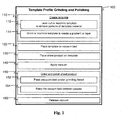
- FIG. 1 illustrates an exemplary method 100 for the manufacture of sheet product of varying surface profile in accordance with the disclosed invention.
- the process begins in step 110 with the creation of a profiling template.
- the profiling template is formed of steel.
- the profiling template should be sized such that it fits securely onto a suitable support surface, thus forming an air tight seal between the profiling template and the support surface, for example sized such that it fits inside an o-ring groove.
- the profiling template can be ground or machined as in step 114 to create a gradient or taper along any portion of the template.
- the template is laser cut or machined in step 112 to remove any number of portions of the template in any size or shape. As an example circles with 50 mm diameters may be formed.
- FIG. 2A illustrates an exemplary system for the manufacture of sheet products having a varying surface profile for use in accordance with one embodiment of the disclosed invention. While the profiling template 220 illustrated in FIG. 2A , which is made of thin steel, has been laser cut to remove circular portions 222 of the profiling template 220, the disclosed invention envisions that the portions 222 could be of any shape or size such as, for example, circles with 50 mm diameters.
- FIG. 2B illustrates an exemplary profiling template 220 for the manufacture of sheet product 200 of varying surface profile for use in accordance with the disclosed invention.
- the profiling template 220 has been ground or machined to create a gradient or taper 227 and laser cut or machined to remove an oval portion 223 and a polygonal portion 224.
- the portions illustrated in profiling template 220 in FIGS. 2A-B are shown as circular 222, oval 223, and polygonal 224, it is to be understood that the portions can take on any desired shape depending upon the final surface profile desired.
- the profiling template 220 is placed on the support surface of the grinding machine in step 120, which acts as a datum surface.
- the support surface is a vacuum bed 240 and the profiling template 220 is placed inside an o-ring groove 250.
- the sheet product 200 to be processed is then placed on top of the profiling template 220, extending outside the o-ring 250, and is conformed to the profiling template 220 in any suitable way.
- a sheet product that measures 500 mm x 1000 mm and has thickness between 0.5 mm and 2.0 mm may be used.
- a vacuum can be applied at any point in this process by the vacuum bed 240.
- This can be accomplished by the utilization of any suitable means for applying a suction to the vacuum bed 240, e.g., by use of a vacuum pump.
- the support surface can be any suitable surface for permitting and enabling the sheet product to be pressed against the profiling template. Examples include the use of adhesive methods or by use of mechanical methods, e.g., by applying pneumatic pressure.
- FIG. 3A illustrates a cross-sectional view of an exemplary profiling template 220 placed between the sheet product 200 and vacuum bed 240 .
- the vacuum bed 240 will require an evacuation channel 328 and can be of any suitable type, e.g., a custom made vacuum bed 240 with an o-ring groove 250 (not shown in FIGS. 3A-D ).
- FIG. 3B illustrates a cross-sectional side view of an exemplary sheet product 200 , profiling template 220 , and vacuum bed 240 while a vacuum is applied though evacuation channel 328 .
- the applied vacuum draws the sheet product 200 down into the cavities 222 , and away from a grinding plane 300.
- Those portions of the sheet product 200 that lie above the grinding plane 300 can be removed by grinding head 260.
- the grinding head 260 can be any suitable device for removing material from the sheet product 200 , and will vary depending on the constitution of the sheet product 200 .
- an appropriate grinding head can be either fixed or belt, with belts between 60 grit and 240 grit SiC or Al 2 O 3 grinding media.
- the grinding head 260 can be a stationary head, or it can move along one or more axes, e.g., the vertical axis relative to the sheet product, or along rotational axes.
- the vacuum bed 240 can also be stationary (in which case the grinding head 260 would move in at least one horizontal direction) or the vacuum bed 240 can have the capacity to move in one or more axes, including rotational axes.
- step 150 the vacuum bed 240 is passed under the grinding head 260 to grind and/or polish the sheet product 200.
- the vacuum bed 240 can be passed under the grinding head 260 in step 152 in multiple directions, one or more times. After each pass, the vacuum bed 240 can be raised in step 154 to decrease the gap between the vacuum bed 240 and the grinding head 260.
- the vacuum bed 240 is repeatedly passed under the grinding head 260 in step 150 until the desired surface profile of the sheet product 200 is achieved.
- FIG. 3C illustrates a cross-sectional side view of an exemplary sheet product 200, profiling template 220, and vacuum bed 240 after the vacuum bed 240 has been passed under the grinding head 260 along grinding plane 300 to reduce the overall surface profile (varying thicknesses across the surface on one or both sides) of sheet product 200.
- the vacuum can be released in step 160.
- the parts of sheet product 200 that were drawn into the cavities in the template can return to the grinding plane.
- the resulting sheet product has a new surface profile.
- the resulting sheet product 200 will also have given surface roughness depending on the type of grinding head 260 utilized and amount of processing performed.
- FIG. 3D illustrates an exemplary sheet product 200, template 220 , and vacuum bed 240 after the vacuum has been released.
- the resulting sheet product 200 has a new surface profile with reduced thickness overall, for example a thickness of 0.5 mm at the thinnest point, but can have the original, or another desired thickness, where the sheet product 200 was drawn down into the cavities created by removed portions 222 of the profiling template 220. This is indicated by the surface protrusion 230 shown in FIG. 3D .
- the sheet product 200 would have the original thickness, for example, where the portions of the sheet product 200 were drawn down into the cavities 222 at a depth below the grinding plane 300.
- FIG. 8A is a photo of an exemplary sheet product 200 profiled using the method shown in FIG. 1 , wherein the sheet product 200 has been drawn down into the cavities created by removed portions 222, and is part way through the grinding process. A number of circular- shaped surface indentations 230 are visible in FIG. 8A and it can be seen that these surface indentations 230 have retained the original surface finish.
- FIG. 8B is a photo of the exemplary profiling template 220, used to create the sheet product shown in FIG. 8A . As shown in FIG. 8B , profiling template 220 is made of 0.5 mm sheet steel, and has been laser cut to remove circular portions 222 of approximately 25 mm to 200 mm diameter.
- the vacuum bed 240 shown in FIG. 8B is an aluminum custom-made bed approximately 1.5 m x 1 m.
- FIG. 8B is also illustrated in FIG. 2A as template 220.
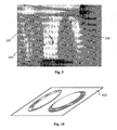
- FIG. 9 is a photo of an exemplary sheet product of Ti 6-4 alloy measuring 685 mm x 1195 mm, which has been profiled using the method shown in FIG. 1 .
- the sheet product shown in FIG. 9 has been drawn down into the cavities created by oval portion 223 and polygonal portion 224, thereby producing the oval protrusion 225, and polygonal protrusion 226, respectively, as shown in FIG. 9 .
- the profiled sheet product has also been ground to create a gradient or taper (not visible).
- the profiling template used to create the exemplary sheet product shown in FIG. 9 is illustrated as profiling template 220 in FIG. 2B .
- the resulting surface profile of the sheet product 200 varies in thickness from 0.60 to 1.40 mm.
- FIG. 4 illustrates a method 400 for the manufacture of sheet product 200 of varying surface profile (not in accordance with the present invention).
- the process begins at step 410 with the creation of the contoured support surface of the grinding machine, which acts as a datum surface.
- the contoured support surface can be formed of any suitable material, for example aluminum.
- the contoured support surface can be a contoured vacuum bed.
- the support surface can by any surface suitable to permit and enable the sheet product to be conformed thereto.
- an exemplary contoured vacuum bed may be formed by machining the material of a vacuum bed in step 410.
- the contoured vacuum bed may be machined in step 412 to remove any number of portions of the vacuum bed in any size, shape, or angle, and depth.
- the vacuum bed may be machined to remove portions up to 0.5 mm deep.
- the contoured vacuum bed may be machined as in step 414 to create high spots on the contoured vacuum bed in any size, shape, angle, or height.
- FIG. 5 illustrates an exemplary contoured vacuum bed 540, which can be machined to remove cavities 542 of any shape such as, for example, a circular shape from the contoured vacuum bed 540.
- the exemplary contoured vacuum bed 540 can be machined to create high spots 546 in the contoured vacuum bed 540.
- step 420 the sheet product is placed onto the contoured vacuum bed 540 and is conformed to the contoured vacuum bed 540 in any suitable way.
- a vacuum can be applied at any point in this process by the contoured vacuum bed 540. This can be accomplished by the utilization of any suitable means for applying a suction to the contoured vacuum bed.
- the contoured vacuum bed 540 can be machined with an o-ling groove 250.
- a plurality of evacuation channels are provided across the surface of the contoured vacuum bed 540 to ensure conformance of the sheet product 200 to its surface.
- the number of evacuation channels required generally depends on the complexity of the surface profile provided on the contoured vacuum bed 540.
- the sheet product 200 can be conformed to the support surface by any other suitable means such as, for example, by use of adhesive methods or by use of mechanical methods, e.g., by applying pneumatic pressure.
- FIG. 6 illustrates an exemplary grinding head 260 and contoured vacuum bed 540, which can be machined to remove cavities 542 of any shape, for example a circular shape.
- the grinding head 260 may be a cylinder with a 300 mm diameter and length of 850 mm.
- FIG. 7 illustrates a cross-sectional side view of an exemplary sheet product 200 that has been conformed into cavities 542 and over high spots 546 in the contoured vacuum bed 540.
- the contoured vacuum bed 540 is passed under the grinding head 260 to grind and/or polish the sheet product in step 440.
- the contoured vacuum bed 540 can be passed under the grinding head 260 in multiple directions, one or more times. After each pass, in step 444 the contoured vacuum bed 540 can be raised to decrease the gap between the contoured vacuum bed 540 and the grinding head 260.
- the contoured vacuum bed may be passed under the grinding head 260 the desired number of times as in step 442 until the desired overall surface profile of the sheet product 200 is achieved.
- the cross-sectional side view of the exemplary grinding head 260, sheet product 200, and contoured vacuum bed 540 shown in FIG. 7 also provides an illustrative grinding plane 300. After the vacuum bed has been passed under the grinding head 260 along grinding plane 300 the desired number of times, the overall surface profile (varying thickness across one or both sides) of sheet product 200 is reduced.
- the vacuum is released in step 450.
- the resulting sheet product has a new surface profile.
- the resulting sheet product 200 will have given surface roughness depending on the utilized grinding head.
- FIG. 10 is a perspective view of a resulting sheet product 200 profiled using the method shown in FIG. 4 arid the contoured vacuum bed 540 provided in FIG. 5 .
- the presence of a high spot 546 creates a surface cavity on the profiled sheet product (shown at left in Fig. 10 ) whereas a cavity 542 creates a surface protrusion on the resulting sheet product (at right in Fig. 10 ).
Landscapes
- Engineering & Computer Science (AREA)
- Mechanical Engineering (AREA)
- Grinding And Polishing Of Tertiary Curved Surfaces And Surfaces With Complex Shapes (AREA)
- Grinding Of Cylindrical And Plane Surfaces (AREA)
- Polishing Bodies And Polishing Tools (AREA)
- Moulds For Moulding Plastics Or The Like (AREA)
Description
- The present invention relates generally to methods for profiling a surface of a metal (i.e. metal or a metallic alloy) sheet product.
- Thin gauge sheet product having tight tolerance (such as, for example, ± 0.05 mm) can be manufactured by grinding and polishing the sheet product using a belt-grinding machine. The belt-grinding machine generally includes an abrasive grinding head and a vacuum bed which holds the sheet product flat in position and acts as a datum face to a grinding head. The grinding head itself is typically comprised of a fixed cylinder, around which a grinding belt passes. The vacuum bed, alternatively known as a vacuum chuck, generally has an o-ring groove machined into it such that a vacuum may be applied to hold the sheet product in position on the vacuum bed during grinding.
- A conventional process to grind and polish flat thin gauge sheet product includes placing the sheet on the vacuum bed, holding the sheet product flat in position by applying a vacuum followed by passing the vacuum bed under a fixed grinding head numerous times. After each pass, the bed is raised to decrease the gap between the vacuum bed and the grinding head, thus grinding off and thinning the sheet product uniformly across the entire width of the sheet product.
- Alternatively, the process to grind and polish tapered thin gauge sheet product can include passing the bed under the grinding head while gradually raising or lowering the bed between two set positions during each pass to gradually change the thickness of the sheet product between the set positions. This technique creates a tapered change in thickness which is uniform across the entire width of the sheet product.
- In either of the above cases, the resultant sheet product is of substantially uniform thickness across the full width (i.e., the direction perpendicular to the grinding direction) of the sheet product, with a given surface roughness which itself depends on the grade of abrasive belt utilized and the number of passes performed.
- A sheet product with uniform thickness across the full width of the sheet can, in some instances, have an impact on its performance. For example, where increased rigidity or additional material is required in certain regions, an as-formed sheet product must have the additional thickness across its full width. This additional material increases the final component weight and can potentially hinder performance. Both of these results can create additional costs which is undesirable to users of sheet product.
US 3,932,148 describes how to make complex aspheric optical surfaces. In the disclosed method, one surface of a relatively thick glass block is ground and polished to the desired aspheric surface, which may be tested in a system including master optics of the remaining components. This master die block may then be used to generate reverse die plates by drawing thin glass blanks against the configured surface thereof and polishing to an optical flat. These reverse die plates are then mounted on a base die block and deformable glass blanks are drawn against the configured surface thereof and the opposite surface polished to an optical flat. Upon removal, the glass blanks assume a curvature identical to the original aspheric surface of the master die block.US 3,881,373 describes a method of making a substantially spherical outer blade for rotary electric shavers, which is countersunk smoothly around hair inlet holes. In the disclosed method, a die having alternate and continuous convex and concave parts is used, either one of which convex and concave parts correspond to the hair inlet holes and are provided with a curved surface of desired radius of curvature at a shoulder part of each convex part. A metal lamina placed between the die and a soft plate material is pressed so as to be plastically deformed conforming to the die surface, and the deformed lamina is subjected to mechanical, chemical or electrochemical grinding to form the hair inlet holes. - Accordingly, there exists a need in the art for a cost effective technique for producing a sheet product of controlled, variable thickness, which is both sufficiently controllable and repeatable to be utilized as a commercial manufacturing process.
- In view of the above-describe problems, needs, and goals, the present invention provides techniques for manufacturing sheet product of varying surface profile and products thus manufactured.
- In one embodiment, a method for profiling a metal sheet product having a first profile on a first surface is provided. The method comprises:
- (a) creating a profiling template made of steel that has been laser cut or machined to remove portions of the template;
- (b) arranging said profiling template between said metal sheet product and a vacuum bed support surface;
- (c) applying a vacuum force to said arrangement of said profiling template and said metal sheet product to conform said metal sheet product to said profiling template such that said conformance causes said metal sheet product to have a second surface profile on said first surface; and
- (d) processing said first surface of the metal sheet product to form a third surface profile with a grinding head, wherein said metal sheet product is released from said conformance after processing has been performed such that said metal sheet product has a fourth surface profile on said first surface.
- The sheet product is released from conformance with the profiling template such that the sheet product has a fourth surface profile on the first surface. The support surface is a vacuum bed, and conforming the sheet product to the profiling template involves applying a vacuum force to the arrangement of the profiling template and the sheet product. The first surface may be processed by repeated passes of the grinding head. The separation between the grinding head and the arrangement of the profiling template and sheet product may also be reduced between passes of the grinding head.
- Additional preferred features of the present invention are set forth in the dependent claims appended hereto.
- The accompanying drawings, which are incorporated and constitute part of this disclosure, illustrate exemplary embodiments of the disclosed invention and serve to explain the principles of the disclosed invention.
-
-
FIG. 1 is a flowchart illustrating a method in accordance with an exemplary embodiment of the present invention. -
FIG. 2A is a perspective view of a sheet product, profiling template, and vacuum bed for use in accordance with an embodiment of the present invention. -
FIG. 2B is a perspective view of a profiling template and sheet product, where the profiling template has been machined to create a gradient and to remove portions thereof for use in accordance with an embodiment of the present invention. -
FIG. 3A is a cross-sectional side view of the sheet product, profiling template, and vacuum bed shown inFIG. 2A for use in accordance with an embodiment of the present invention. -
FIG. 3B is a side view of a state of the sheet product, profiling template, and vacuum bed shown inFIG. 2A , where a vacuum is applied to the sheet product and the vacuum bed is passed under a grinding head, for use in accordance with an embodiment of the present invention. -
FIG. 3C is a side view of a state of the sheet product, profiling template, and vacuum bed shown inFIG. 2A , where a vacuum is applied to the sheet product and the vacuum bed has been passed under a grinding head to reduce overall thickness of the sheet product, for use in accordance with an embodiment of the present invention. -
Fig. 3D is a side view of a state of the sheet product, profiling template, and vacuum bed shown inFIG. 2A , where the vacuum is released and the sheet product regains its original shape, for use in accordance with an embodiment of the present invention. -
FIG. 4 is a flowchart illustrating a method not in accordance with the present invention. -
FIG. 5 is a perspective view of a contoured vacuum bed not in accordance with the present invention. -
FIG. 6 is a perspective view of a grinding head and another contoured vacuum bed not in accordance with the present invention. -
FIG. 7 is a cross-sectional side view of a grinding head, sheet product, and profiling vacuum bed not in accordance with the present invention. -
FIG. 8A is a photograph of a resulting sheet product for use in accordance with an exemplary embodiment of the present invention. -
FIG. 8B is a photograph of a profiling template for use in accordance with an exemplary embodiment of the present invention. -
FIG. 9 is a photograph of a resulting sheet product formed in accordance with another exemplary embodiment of the present invention. -
FIG. 10 is a perspective view of a resulting sheet product not in accordance with the present invention. - Throughout the drawings, the same reference numerals and characters, unless otherwise stated, are used to denote like features, elements, components or portions of the illustrated embodiments. Moreover, while the disclosed invention will now be described in detail with reference to the figures, it is done so in connection with the illustrative embodiments.
- The present invention provides techniques for the manufacture of sheet product having a varying surface profile that reduces or prevents increase of the overall weight of the sheet product and is well suited for any application where varying surface profile may be required of the final product and where repeatability of tight tolerances is desired. Thus, the disclosed techniques enable the resulting sheet product to have varying surface profile changes both along the length and across the width of the sheet. Such changes can be varied in terms of starting and ending points of the surface profile changes, and can occur along curved or straight lines.
-
FIG. 1 illustrates anexemplary method 100 for the manufacture of sheet product of varying surface profile in accordance with the disclosed invention. As shown inFIG. 1 , the process begins instep 110 with the creation of a profiling template. The profiling template is formed of steel. - The profiling template should be sized such that it fits securely onto a suitable support surface, thus forming an air tight seal between the profiling template and the support surface, for example sized such that it fits inside an o-ring groove. In one embodiment, the profiling template can be ground or machined as in
step 114 to create a gradient or taper along any portion of the template. The template is laser cut or machined instep 112 to remove any number of portions of the template in any size or shape. As an example circles with 50 mm diameters may be formed. -
FIG. 2A illustrates an exemplary system for the manufacture of sheet products having a varying surface profile for use in accordance with one embodiment of the disclosed invention. While theprofiling template 220 illustrated inFIG. 2A , which is made of thin steel, has been laser cut to removecircular portions 222 of theprofiling template 220, the disclosed invention envisions that theportions 222 could be of any shape or size such as, for example, circles with 50 mm diameters. -
FIG. 2B illustrates anexemplary profiling template 220 for the manufacture ofsheet product 200 of varying surface profile for use in accordance with the disclosed invention. Theprofiling template 220 has been ground or machined to create a gradient ortaper 227 and laser cut or machined to remove anoval portion 223 and apolygonal portion 224. Although the portions illustrated inprofiling template 220 inFIGS. 2A-B are shown as circular 222, oval 223, andpolygonal 224, it is to be understood that the portions can take on any desired shape depending upon the final surface profile desired. - Returning to
FIG. 1 andFIGS. 2A-B , following the creation of the template instep 110, theprofiling template 220 is placed on the support surface of the grinding machine instep 120, which acts as a datum surface. In an exemplary embodiment, the support surface is avacuum bed 240 and theprofiling template 220 is placed inside an o-ring groove 250. Instep 130, thesheet product 200 to be processed is then placed on top of theprofiling template 220, extending outside the o-ring 250, and is conformed to theprofiling template 220 in any suitable way. The disclosed invention envisions that thesheet product 200 could be of any length, width, and thickness. A sheet product that measures 500 mm x 1000 mm and has thickness between 0.5 mm and 2.0 mm may be used. - In an exemplary embodiment, in step 140 a vacuum can be applied at any point in this process by the
vacuum bed 240. This can be accomplished by the utilization of any suitable means for applying a suction to thevacuum bed 240, e.g., by use of a vacuum pump. In the same or another embodiment, the support surface can be any suitable surface for permitting and enabling the sheet product to be pressed against the profiling template. Examples include the use of adhesive methods or by use of mechanical methods, e.g., by applying pneumatic pressure. -
FIG. 3A illustrates a cross-sectional view of anexemplary profiling template 220 placed between thesheet product 200 andvacuum bed 240. Thevacuum bed 240 will require anevacuation channel 328 and can be of any suitable type, e.g., a custom madevacuum bed 240 with an o-ring groove 250 (not shown inFIGS. 3A-D ). -
FIG. 3B illustrates a cross-sectional side view of anexemplary sheet product 200,profiling template 220, andvacuum bed 240 while a vacuum is applied thoughevacuation channel 328. Where parts of thesheet product 200 can lay above cavities created by removedportions 222 of thetemplate 220, the applied vacuum draws thesheet product 200 down into thecavities 222, and away from a grindingplane 300. Those portions of thesheet product 200 that lie above the grindingplane 300 can be removed by grindinghead 260. - The grinding
head 260 can be any suitable device for removing material from thesheet product 200, and will vary depending on the constitution of thesheet product 200. For example, if thesheet product 200 is a titanium or titanium alloy sheet, an appropriate grinding head can be either fixed or belt, with belts between 60 grit and 240 grit SiC or Al2O3 grinding media. In addition, the grindinghead 260 can be a stationary head, or it can move along one or more axes, e.g., the vertical axis relative to the sheet product, or along rotational axes. Similarly, thevacuum bed 240 can also be stationary (in which case the grindinghead 260 would move in at least one horizontal direction) or thevacuum bed 240 can have the capacity to move in one or more axes, including rotational axes. - Returning to
FIG. 1 andFIGS. 3A-B , after the vacuum is applied, instep 150 thevacuum bed 240 is passed under the grindinghead 260 to grind and/or polish thesheet product 200. Thevacuum bed 240 can be passed under the grindinghead 260 instep 152 in multiple directions, one or more times. After each pass, thevacuum bed 240 can be raised instep 154 to decrease the gap between thevacuum bed 240 and the grindinghead 260. Thevacuum bed 240 is repeatedly passed under the grindinghead 260 instep 150 until the desired surface profile of thesheet product 200 is achieved. -
FIG. 3C illustrates a cross-sectional side view of anexemplary sheet product 200,profiling template 220, andvacuum bed 240 after thevacuum bed 240 has been passed under the grindinghead 260 along grindingplane 300 to reduce the overall surface profile (varying thicknesses across the surface on one or both sides) ofsheet product 200. - Returning to
FIG. 1 , after the desired surface profile of thesheet product 200 is achieved, the vacuum can be released in step 160. By releasing the vacuum, the parts ofsheet product 200 that were drawn into the cavities in the template can return to the grinding plane. The resulting sheet product has a new surface profile. The resultingsheet product 200 will also have given surface roughness depending on the type of grindinghead 260 utilized and amount of processing performed. -
FIG. 3D illustrates anexemplary sheet product 200,template 220, andvacuum bed 240 after the vacuum has been released. The resultingsheet product 200 has a new surface profile with reduced thickness overall, for example a thickness of 0.5 mm at the thinnest point, but can have the original, or another desired thickness, where thesheet product 200 was drawn down into the cavities created by removedportions 222 of theprofiling template 220. This is indicated by thesurface protrusion 230 shown inFIG. 3D . Thesheet product 200 would have the original thickness, for example, where the portions of thesheet product 200 were drawn down into thecavities 222 at a depth below the grindingplane 300. -
FIG. 8A is a photo of anexemplary sheet product 200 profiled using the method shown inFIG. 1 , wherein thesheet product 200 has been drawn down into the cavities created by removedportions 222, and is part way through the grinding process. A number of circular- shapedsurface indentations 230 are visible inFIG. 8A and it can be seen that thesesurface indentations 230 have retained the original surface finish.FIG. 8B is a photo of theexemplary profiling template 220, used to create the sheet product shown inFIG. 8A . As shown inFIG. 8B ,profiling template 220 is made of 0.5 mm sheet steel, and has been laser cut to removecircular portions 222 of approximately 25 mm to 200 mm diameter. Thevacuum bed 240 shown inFIG. 8B is an aluminum custom-made bed approximately 1.5 m x 1 m.FIG. 8B is also illustrated inFIG. 2A astemplate 220. -
FIG. 9 is a photo of an exemplary sheet product of Ti 6-4 alloy measuring 685 mm x 1195 mm, which has been profiled using the method shown inFIG. 1 . The sheet product shown inFIG. 9 has been drawn down into the cavities created byoval portion 223 andpolygonal portion 224, thereby producing theoval protrusion 225, andpolygonal protrusion 226, respectively, as shown inFIG. 9 . The profiled sheet product has also been ground to create a gradient or taper (not visible). The profiling template used to create the exemplary sheet product shown inFIG. 9 is illustrated as profilingtemplate 220 inFIG. 2B . As illustrated by the surface markings provided on thesheet product 200 inFIG. 9 , the resulting surface profile of thesheet product 200 varies in thickness from 0.60 to 1.40 mm. -
FIG. 4 illustrates amethod 400 for the manufacture ofsheet product 200 of varying surface profile (not in accordance with the present invention). As shown inFIG. 4 , the process begins atstep 410 with the creation of the contoured support surface of the grinding machine, which acts as a datum surface. The contoured support surface can be formed of any suitable material, for example aluminum. In an example, the contoured support surface can be a contoured vacuum bed. In the same or another example, the support surface can by any surface suitable to permit and enable the sheet product to be conformed thereto. - As shown in
FIG. 4 , an exemplary contoured vacuum bed may be formed by machining the material of a vacuum bed instep 410. In one example, the contoured vacuum bed may be machined instep 412 to remove any number of portions of the vacuum bed in any size, shape, or angle, and depth. In one example, the vacuum bed may be machined to remove portions up to 0.5 mm deep. In the same or another example, the contoured vacuum bed may be machined as instep 414 to create high spots on the contoured vacuum bed in any size, shape, angle, or height. -
FIG. 5 illustrates an exemplary contouredvacuum bed 540, which can be machined to removecavities 542 of any shape such as, for example, a circular shape from the contouredvacuum bed 540. In the same or another example, the exemplary contouredvacuum bed 540 can be machined to createhigh spots 546 in the contouredvacuum bed 540. - Returning to
FIG. 4 , following the creation of the contouredvacuum bed 540, instep 420 the sheet product is placed onto the contouredvacuum bed 540 and is conformed to the contouredvacuum bed 540 in any suitable way. In an example, in step 430 a vacuum can be applied at any point in this process by the contouredvacuum bed 540. This can be accomplished by the utilization of any suitable means for applying a suction to the contoured vacuum bed. In an example, the contouredvacuum bed 540 can be machined with an o-ling groove 250. A plurality of evacuation channels (not shown) are provided across the surface of the contouredvacuum bed 540 to ensure conformance of thesheet product 200 to its surface. The number of evacuation channels required generally depends on the complexity of the surface profile provided on the contouredvacuum bed 540. In the same or another embodiment, thesheet product 200 can be conformed to the support surface by any other suitable means such as, for example, by use of adhesive methods or by use of mechanical methods, e.g., by applying pneumatic pressure. -
FIG. 6 illustrates anexemplary grinding head 260 and contouredvacuum bed 540, which can be machined to removecavities 542 of any shape, for example a circular shape. In one embodiment, the grindinghead 260 may be a cylinder with a 300 mm diameter and length of 850 mm. -
FIG. 7 illustrates a cross-sectional side view of anexemplary sheet product 200 that has been conformed intocavities 542 and overhigh spots 546 in the contouredvacuum bed 540. - Returning to
FIG. 4 , after the vacuum is applied instep 430, the contouredvacuum bed 540 is passed under the grindinghead 260 to grind and/or polish the sheet product instep 440. Instep 442, the contouredvacuum bed 540 can be passed under the grindinghead 260 in multiple directions, one or more times. After each pass, instep 444 the contouredvacuum bed 540 can be raised to decrease the gap between the contouredvacuum bed 540 and the grindinghead 260. The contoured vacuum bed may be passed under the grindinghead 260 the desired number of times as instep 442 until the desired overall surface profile of thesheet product 200 is achieved. - The cross-sectional side view of the exemplary grinding
head 260,sheet product 200, and contouredvacuum bed 540 shown inFIG. 7 also provides an illustrative grindingplane 300. After the vacuum bed has been passed under the grindinghead 260 along grindingplane 300 the desired number of times, the overall surface profile (varying thickness across one or both sides) ofsheet product 200 is reduced. - Returning to
FIG. 4 , after the desired surface profile of thesheet product 200 is achieved, the vacuum is released instep 450. The resulting sheet product has a new surface profile. The resultingsheet product 200 will have given surface roughness depending on the utilized grinding head. -
FIG. 10 is a perspective view of a resultingsheet product 200 profiled using the method shown inFIG. 4 arid the contouredvacuum bed 540 provided inFIG. 5 . The presence of ahigh spot 546 creates a surface cavity on the profiled sheet product (shown at left inFig. 10 ) whereas acavity 542 creates a surface protrusion on the resulting sheet product (at right inFig. 10 ). - It will be appreciated by persons skilled in the art that the present invention is not limited to what has been particularly shown and described in this specification. Rather, the scope of the present invention is defined by the claims which follow. It should further be understood that the above description is only representative of illustrative examples of embodiments. For the reader's convenience, the above description has focused on a representative sample of possible embodiments, a sample that teaches the principles of the present invention. Other embodiments may result from a different combination of portions of different embodiments.
- The description has not attempted to exhaustively enumerate all possible variations.
Claims (7)
- A method for profiling a metal sheet product (200) having a first profile on a first surface, comprising:(a) creating a profiling template (220) made of steel that has been laser cut or machined to remove portions (222) of the template (220);(b) arranging said profiling template (220) between said metal sheet product (200) and a vacuum bed (240) support surface;(c) applying a vacuum force to said arrangement of said profiling template (220) and said metal sheet product (200) to conform said metal sheet product (200) to said profiling template (220) such that said conformance causes said metal sheet product (200) to have a second surface profile on said first surface; and(d) processing said first surface of the metal sheet product (200) to form a third surface profile with a grinding head (260), wherein said metal sheet product (200) is released from said conformance after processing has been performed such that said metal sheet product (200) has a fourth surface profile on said first surface.
- The method of claim 1, wherein said metal sheet product (200) is made of a Ti 6-4 alloy.
- The method of claim 1, wherein said metal sheet product (200) has a thickness of between 0.5 mm and 2.0 mm.
- The method of claim 3, wherein said metal sheet product (200) measures 500 mm x 1000 mm.
- The method of claim 2, wherein said grinding head (260) comprises SiC or Al2O3 grinding media, with belts between 60 and 240 grit SiC or Al2O3 grinding media.
- The method of claim 1, wherein said first surface is processed by repeated passes of the grinding head (260).
- The method of claim 6, wherein a separation between the grinding head (260) and said arrangement of said profiling template and said metal sheet product (200) is reduced between passes.
Priority Applications (1)
| Application Number | Priority Date | Filing Date | Title |
|---|---|---|---|
| EP11194676.0A EP2433739B1 (en) | 2009-02-27 | 2010-02-26 | Systems and methods for profiling sheet products |
Applications Claiming Priority (2)
| Application Number | Priority Date | Filing Date | Title |
|---|---|---|---|
| US15635009P | 2009-02-27 | 2009-02-27 | |
| PCT/US2010/025537 WO2010099409A1 (en) | 2009-02-27 | 2010-02-26 | Systems and methods for profiling sheet products |
Related Child Applications (2)
| Application Number | Title | Priority Date | Filing Date |
|---|---|---|---|
| EP11194676.0A Division-Into EP2433739B1 (en) | 2009-02-27 | 2010-02-26 | Systems and methods for profiling sheet products |
| EP11194676.0A Division EP2433739B1 (en) | 2009-02-27 | 2010-02-26 | Systems and methods for profiling sheet products |
Publications (2)
| Publication Number | Publication Date |
|---|---|
| EP2401113A1 EP2401113A1 (en) | 2012-01-04 |
| EP2401113B1 true EP2401113B1 (en) | 2015-08-12 |
Family
ID=42101338
Family Applications (2)
| Application Number | Title | Priority Date | Filing Date |
|---|---|---|---|
| EP10706457.8A Active EP2401113B1 (en) | 2009-02-27 | 2010-02-26 | Systems and methods for profiling sheet products |
| EP11194676.0A Active EP2433739B1 (en) | 2009-02-27 | 2010-02-26 | Systems and methods for profiling sheet products |
Family Applications After (1)
| Application Number | Title | Priority Date | Filing Date |
|---|---|---|---|
| EP11194676.0A Active EP2433739B1 (en) | 2009-02-27 | 2010-02-26 | Systems and methods for profiling sheet products |
Country Status (8)
| Country | Link |
|---|---|
| US (1) | US8303379B2 (en) |
| EP (2) | EP2401113B1 (en) |
| JP (1) | JP5364175B2 (en) |
| CN (1) | CN102333618B (en) |
| BR (1) | BRPI1008773B1 (en) |
| CA (1) | CA2753880C (en) |
| RU (1) | RU2518811C2 (en) |
| WO (1) | WO2010099409A1 (en) |
Families Citing this family (2)
| Publication number | Priority date | Publication date | Assignee | Title |
|---|---|---|---|---|
| JP7020806B2 (en) * | 2017-06-21 | 2022-02-16 | トヨタ自動車株式会社 | Manufacturing method of metal parts |
| CN108296341A (en) * | 2018-04-13 | 2018-07-20 | 宁波得晴电器科技有限公司 | A kind of bolster moulding process |
Family Cites Families (25)
| Publication number | Priority date | Publication date | Assignee | Title |
|---|---|---|---|---|
| US873340A (en) * | 1904-08-19 | 1907-12-10 | Edward Bagnall | Machine for grinding, smoothing, and polishing plate-glass. |
| US2964089A (en) * | 1957-06-19 | 1960-12-13 | Kunz Walter | Sheet metal shaping machine |
| GB952358A (en) | 1959-09-08 | 1964-03-18 | John Aubrey Grainger | Improvements relating to methods of an apparatus for flow-working of metals |
| FR2097216A5 (en) * | 1970-05-27 | 1972-03-03 | Anvar | |
| JPS6055123B2 (en) * | 1972-10-26 | 1985-12-03 | 松下電工株式会社 | Electric razor outer blade manufacturing method |
| US3889431A (en) * | 1973-09-04 | 1975-06-17 | Celestron Pacific | Method for making schmidt corrector lenses |
| US3837124A (en) * | 1973-09-26 | 1974-09-24 | Celestron Pacific | Method for making replica contour block masters for producing schmidt corrector plates |
| US3881373A (en) * | 1974-03-13 | 1975-05-06 | Matsushita Electric Works Ltd | Method of making outer blade for electric shaver |
| JPS5165950A (en) * | 1974-12-02 | 1976-06-08 | Jei Jonson Toomasu | SHUMITSUTOHOSEIRENZUNO SEIZOHOHO |
| US3932148A (en) * | 1975-01-21 | 1976-01-13 | Criterion Manufacturing Company, Inc. | Method and apparatus for making complex aspheric optical surfaces |
| JPS5841869B2 (en) * | 1975-04-03 | 1983-09-14 | 松下電工株式会社 | electric razor |
| SU695742A1 (en) * | 1977-07-01 | 1979-11-05 | Borushnov Vladimir | Die for pressing with elastic medium |
| US4474095A (en) * | 1983-01-17 | 1984-10-02 | Heck Philip H | Nibbling machine |
| US4671145A (en) * | 1983-12-23 | 1987-06-09 | Basf Aktiengesellschaft | Method and apparatus for the surface machining of substrate plates for magnetic memory plates |
| JPS62128780A (en) | 1985-11-29 | 1987-06-11 | Toshiba Corp | Printing apparatus |
| JPS63293042A (en) * | 1987-05-26 | 1988-11-30 | Tsutomu Yamana | Method for forming pattern on elastic sheet |
| IT1233959B (en) | 1989-02-06 | 1992-04-22 | Elma Di Fabbri Angelo | MACHINE FOR CUTTING PLATE DISCS |
| DE19628333A1 (en) * | 1996-07-13 | 1998-01-15 | Schuler Pressen Gmbh & Co | Transfer device for sheet metal parts in a press system |
| FR2755886B1 (en) | 1996-11-18 | 1998-12-31 | Sarrion Sanchez Christian | DEVICE FOR STRAIGHTENING METAL OR PLASTIC ELEMENTS |
| JP2001044116A (en) * | 1999-01-20 | 2001-02-16 | Asm Lithography Bv | Optical correction plate and its application in lithographic projection apparatus |
| US6536250B1 (en) * | 1999-11-05 | 2003-03-25 | Dent Defyer, Inc. | Apparatus and method for vacuum dent repair |
| JP2001334444A (en) * | 2000-05-25 | 2001-12-04 | Toshiba Ceramics Co Ltd | Curved surface processing method for thin plate |
| ITBO20010180A1 (en) * | 2001-03-27 | 2002-09-27 | Jobs Spa | PROCEDURE AND EQUIPMENT FOR THE PRODUCTION OF MANUFACTURES OF A CERTAIN THICKNESS |
| DE10331390A1 (en) * | 2003-07-11 | 2005-01-27 | Carl Zeiss Smt Ag | Aspherical surface production process for optical elements, comprises placing element in mould, introducing medium, and spherically working deformed optical medium |
| JP2006068882A (en) | 2004-09-06 | 2006-03-16 | Nitta Haas Inc | Workpiece holding member |
-
2010
- 2010-02-26 CA CA2753880A patent/CA2753880C/en active Active
- 2010-02-26 CN CN201080009878.1A patent/CN102333618B/en active Active
- 2010-02-26 JP JP2011552183A patent/JP5364175B2/en active Active
- 2010-02-26 BR BRPI1008773-7A patent/BRPI1008773B1/en not_active IP Right Cessation
- 2010-02-26 RU RU2011139331/02A patent/RU2518811C2/en active
- 2010-02-26 EP EP10706457.8A patent/EP2401113B1/en active Active
- 2010-02-26 WO PCT/US2010/025537 patent/WO2010099409A1/en not_active Ceased
- 2010-02-26 EP EP11194676.0A patent/EP2433739B1/en active Active
- 2010-02-26 US US12/713,449 patent/US8303379B2/en active Active
Also Published As
| Publication number | Publication date |
|---|---|
| CA2753880C (en) | 2015-02-10 |
| CN102333618B (en) | 2014-12-03 |
| US20100221569A1 (en) | 2010-09-02 |
| RU2011139331A (en) | 2013-04-10 |
| EP2401113A1 (en) | 2012-01-04 |
| RU2518811C2 (en) | 2014-06-10 |
| BRPI1008773A2 (en) | 2016-03-08 |
| CN102333618A (en) | 2012-01-25 |
| JP2012519084A (en) | 2012-08-23 |
| JP5364175B2 (en) | 2013-12-11 |
| BRPI1008773B1 (en) | 2021-01-05 |
| WO2010099409A1 (en) | 2010-09-02 |
| US8303379B2 (en) | 2012-11-06 |
| CA2753880A1 (en) | 2010-09-02 |
| EP2433739A1 (en) | 2012-03-28 |
| EP2433739B1 (en) | 2017-04-19 |
Similar Documents
| Publication | Publication Date | Title |
|---|---|---|
| KR100558797B1 (en) | Process for machining axial blade slots in turbine disks for jet engines | |
| US9375820B2 (en) | Method and system for finishing glass sheets | |
| US20070234564A1 (en) | Method and apparatus for producing blades | |
| CN103551642B (en) | Cutting tool | |
| US20250042110A1 (en) | Method for Producing Spectacles Lenses, and a Positioning Receptacle for/having a Spectacles Lens Semifinished Product | |
| CN110682054B (en) | Machining method of thin-wall inner groove | |
| KR101925616B1 (en) | Laminated sheet polishing method and apparatus performing the same | |
| CN113414554B (en) | Machining process and tool for large-diameter thin-wall ring workpieces | |
| US5544549A (en) | Process for the production of a steel punching sheet | |
| EP2433739B1 (en) | Systems and methods for profiling sheet products | |
| WO2011115244A1 (en) | Molding method for plate-shaped workpiece, and molded article | |
| KR101805416B1 (en) | Laminated sheet polishing method and apparatus performing the same | |
| US11931793B2 (en) | Inlet lip skin manufacturing method | |
| CN106825614B (en) | A kind of aero-compressor hubcap profile surface processing method | |
| CN121104833A (en) | A method for fabricating large-aperture optical elements | |
| CN110842653B (en) | Processing method of three-dimensional texture, glass part, glass casing and electronic equipment | |
| CN109570587A (en) | A kind of processing method of curvilinear style microchannel cold plates | |
| JP7378717B2 (en) | Cutting inserts and processing methods | |
| JP2010082718A (en) | Lens grinder and grinding dish for aspheric surface | |
| KR20250108149A (en) | Precision processing system and method for semiconductor vacuum pump component lobes | |
| TWI334810B (en) | Method and instrument of conjugate polishing process | |
| CN121511145A (en) | Forming tools and methods for forming workpieces | |
| CN113878438A (en) | Processing method of lens finished product | |
| JP2002326148A (en) | Compound curved surface polishing method | |
| JPH1119342A (en) | Comb blade for combing scissors |
Legal Events
| Date | Code | Title | Description |
|---|---|---|---|
| PUAI | Public reference made under article 153(3) epc to a published international application that has entered the european phase |
Free format text: ORIGINAL CODE: 0009012 |
|
| 17P | Request for examination filed |
Effective date: 20110927 |
|
| AK | Designated contracting states |
Kind code of ref document: A1 Designated state(s): AT BE BG CH CY CZ DE DK EE ES FI FR GB GR HR HU IE IS IT LI LT LU LV MC MK MT NL NO PL PT RO SE SI SK SM TR |
|
| DAX | Request for extension of the european patent (deleted) | ||
| 17Q | First examination report despatched |
Effective date: 20121005 |
|
| RAP1 | Party data changed (applicant data changed or rights of an application transferred) |
Owner name: TITANIUM METALS CORPORATION |
|
| GRAP | Despatch of communication of intention to grant a patent |
Free format text: ORIGINAL CODE: EPIDOSNIGR1 |
|
| INTG | Intention to grant announced |
Effective date: 20150225 |
|
| GRAS | Grant fee paid |
Free format text: ORIGINAL CODE: EPIDOSNIGR3 |
|
| GRAA | (expected) grant |
Free format text: ORIGINAL CODE: 0009210 |
|
| AK | Designated contracting states |
Kind code of ref document: B1 Designated state(s): AT BE BG CH CY CZ DE DK EE ES FI FR GB GR HR HU IE IS IT LI LT LU LV MC MK MT NL NO PL PT RO SE SI SK SM TR |
|
| REG | Reference to a national code |
Ref country code: GB Ref legal event code: FG4D |
|
| REG | Reference to a national code |
Ref country code: CH Ref legal event code: EP |
|
| REG | Reference to a national code |
Ref country code: AT Ref legal event code: REF Ref document number: 741695 Country of ref document: AT Kind code of ref document: T Effective date: 20150815 |
|
| REG | Reference to a national code |
Ref country code: IE Ref legal event code: FG4D |
|
| REG | Reference to a national code |
Ref country code: DE Ref legal event code: R096 Ref document number: 602010026566 Country of ref document: DE |
|
| REG | Reference to a national code |
Ref country code: FR Ref legal event code: PLFP Year of fee payment: 7 |
|
| REG | Reference to a national code |
Ref country code: LT Ref legal event code: MG4D |
|
| REG | Reference to a national code |
Ref country code: AT Ref legal event code: MK05 Ref document number: 741695 Country of ref document: AT Kind code of ref document: T Effective date: 20150812 |
|
| REG | Reference to a national code |
Ref country code: NL Ref legal event code: MP Effective date: 20150812 |
|
| PG25 | Lapsed in a contracting state [announced via postgrant information from national office to epo] |
Ref country code: LV Free format text: LAPSE BECAUSE OF FAILURE TO SUBMIT A TRANSLATION OF THE DESCRIPTION OR TO PAY THE FEE WITHIN THE PRESCRIBED TIME-LIMIT Effective date: 20150812 Ref country code: FI Free format text: LAPSE BECAUSE OF FAILURE TO SUBMIT A TRANSLATION OF THE DESCRIPTION OR TO PAY THE FEE WITHIN THE PRESCRIBED TIME-LIMIT Effective date: 20150812 Ref country code: LT Free format text: LAPSE BECAUSE OF FAILURE TO SUBMIT A TRANSLATION OF THE DESCRIPTION OR TO PAY THE FEE WITHIN THE PRESCRIBED TIME-LIMIT Effective date: 20150812 Ref country code: NO Free format text: LAPSE BECAUSE OF FAILURE TO SUBMIT A TRANSLATION OF THE DESCRIPTION OR TO PAY THE FEE WITHIN THE PRESCRIBED TIME-LIMIT Effective date: 20151112 Ref country code: GR Free format text: LAPSE BECAUSE OF FAILURE TO SUBMIT A TRANSLATION OF THE DESCRIPTION OR TO PAY THE FEE WITHIN THE PRESCRIBED TIME-LIMIT Effective date: 20151113 |
|
| PG25 | Lapsed in a contracting state [announced via postgrant information from national office to epo] |
Ref country code: ES Free format text: LAPSE BECAUSE OF FAILURE TO SUBMIT A TRANSLATION OF THE DESCRIPTION OR TO PAY THE FEE WITHIN THE PRESCRIBED TIME-LIMIT Effective date: 20150812 Ref country code: SE Free format text: LAPSE BECAUSE OF FAILURE TO SUBMIT A TRANSLATION OF THE DESCRIPTION OR TO PAY THE FEE WITHIN THE PRESCRIBED TIME-LIMIT Effective date: 20150812 Ref country code: PL Free format text: LAPSE BECAUSE OF FAILURE TO SUBMIT A TRANSLATION OF THE DESCRIPTION OR TO PAY THE FEE WITHIN THE PRESCRIBED TIME-LIMIT Effective date: 20150812 Ref country code: AT Free format text: LAPSE BECAUSE OF FAILURE TO SUBMIT A TRANSLATION OF THE DESCRIPTION OR TO PAY THE FEE WITHIN THE PRESCRIBED TIME-LIMIT Effective date: 20150812 Ref country code: IS Free format text: LAPSE BECAUSE OF FAILURE TO SUBMIT A TRANSLATION OF THE DESCRIPTION OR TO PAY THE FEE WITHIN THE PRESCRIBED TIME-LIMIT Effective date: 20151212 Ref country code: PT Free format text: LAPSE BECAUSE OF FAILURE TO SUBMIT A TRANSLATION OF THE DESCRIPTION OR TO PAY THE FEE WITHIN THE PRESCRIBED TIME-LIMIT Effective date: 20151214 Ref country code: HR Free format text: LAPSE BECAUSE OF FAILURE TO SUBMIT A TRANSLATION OF THE DESCRIPTION OR TO PAY THE FEE WITHIN THE PRESCRIBED TIME-LIMIT Effective date: 20150812 |
|
| PG25 | Lapsed in a contracting state [announced via postgrant information from national office to epo] |
Ref country code: NL Free format text: LAPSE BECAUSE OF FAILURE TO SUBMIT A TRANSLATION OF THE DESCRIPTION OR TO PAY THE FEE WITHIN THE PRESCRIBED TIME-LIMIT Effective date: 20150812 |
|
| PG25 | Lapsed in a contracting state [announced via postgrant information from national office to epo] |
Ref country code: CZ Free format text: LAPSE BECAUSE OF FAILURE TO SUBMIT A TRANSLATION OF THE DESCRIPTION OR TO PAY THE FEE WITHIN THE PRESCRIBED TIME-LIMIT Effective date: 20150812 Ref country code: IT Free format text: LAPSE BECAUSE OF FAILURE TO SUBMIT A TRANSLATION OF THE DESCRIPTION OR TO PAY THE FEE WITHIN THE PRESCRIBED TIME-LIMIT Effective date: 20150812 Ref country code: EE Free format text: LAPSE BECAUSE OF FAILURE TO SUBMIT A TRANSLATION OF THE DESCRIPTION OR TO PAY THE FEE WITHIN THE PRESCRIBED TIME-LIMIT Effective date: 20150812 Ref country code: SK Free format text: LAPSE BECAUSE OF FAILURE TO SUBMIT A TRANSLATION OF THE DESCRIPTION OR TO PAY THE FEE WITHIN THE PRESCRIBED TIME-LIMIT Effective date: 20150812 Ref country code: DK Free format text: LAPSE BECAUSE OF FAILURE TO SUBMIT A TRANSLATION OF THE DESCRIPTION OR TO PAY THE FEE WITHIN THE PRESCRIBED TIME-LIMIT Effective date: 20150812 |
|
| REG | Reference to a national code |
Ref country code: DE Ref legal event code: R097 Ref document number: 602010026566 Country of ref document: DE |
|
| PG25 | Lapsed in a contracting state [announced via postgrant information from national office to epo] |
Ref country code: BE Free format text: LAPSE BECAUSE OF NON-PAYMENT OF DUE FEES Effective date: 20160229 Ref country code: RO Free format text: LAPSE BECAUSE OF FAILURE TO SUBMIT A TRANSLATION OF THE DESCRIPTION OR TO PAY THE FEE WITHIN THE PRESCRIBED TIME-LIMIT Effective date: 20150812 |
|
| PLBE | No opposition filed within time limit |
Free format text: ORIGINAL CODE: 0009261 |
|
| STAA | Information on the status of an ep patent application or granted ep patent |
Free format text: STATUS: NO OPPOSITION FILED WITHIN TIME LIMIT |
|
| 26N | No opposition filed |
Effective date: 20160513 |
|
| PG25 | Lapsed in a contracting state [announced via postgrant information from national office to epo] |
Ref country code: SI Free format text: LAPSE BECAUSE OF FAILURE TO SUBMIT A TRANSLATION OF THE DESCRIPTION OR TO PAY THE FEE WITHIN THE PRESCRIBED TIME-LIMIT Effective date: 20150812 |
|
| PG25 | Lapsed in a contracting state [announced via postgrant information from national office to epo] |
Ref country code: MC Free format text: LAPSE BECAUSE OF FAILURE TO SUBMIT A TRANSLATION OF THE DESCRIPTION OR TO PAY THE FEE WITHIN THE PRESCRIBED TIME-LIMIT Effective date: 20150812 Ref country code: LU Free format text: LAPSE BECAUSE OF FAILURE TO SUBMIT A TRANSLATION OF THE DESCRIPTION OR TO PAY THE FEE WITHIN THE PRESCRIBED TIME-LIMIT Effective date: 20160226 |
|
| REG | Reference to a national code |
Ref country code: CH Ref legal event code: PL |
|
| PG25 | Lapsed in a contracting state [announced via postgrant information from national office to epo] |
Ref country code: LI Free format text: LAPSE BECAUSE OF NON-PAYMENT OF DUE FEES Effective date: 20160229 Ref country code: CH Free format text: LAPSE BECAUSE OF NON-PAYMENT OF DUE FEES Effective date: 20160229 |
|
| REG | Reference to a national code |
Ref country code: IE Ref legal event code: MM4A |
|
| PG25 | Lapsed in a contracting state [announced via postgrant information from national office to epo] |
Ref country code: BE Free format text: LAPSE BECAUSE OF FAILURE TO SUBMIT A TRANSLATION OF THE DESCRIPTION OR TO PAY THE FEE WITHIN THE PRESCRIBED TIME-LIMIT Effective date: 20150812 |
|
| PG25 | Lapsed in a contracting state [announced via postgrant information from national office to epo] |
Ref country code: IE Free format text: LAPSE BECAUSE OF NON-PAYMENT OF DUE FEES Effective date: 20160226 |
|
| REG | Reference to a national code |
Ref country code: FR Ref legal event code: PLFP Year of fee payment: 8 |
|
| PG25 | Lapsed in a contracting state [announced via postgrant information from national office to epo] |
Ref country code: MT Free format text: LAPSE BECAUSE OF FAILURE TO SUBMIT A TRANSLATION OF THE DESCRIPTION OR TO PAY THE FEE WITHIN THE PRESCRIBED TIME-LIMIT Effective date: 20150812 |
|
| REG | Reference to a national code |
Ref country code: FR Ref legal event code: PLFP Year of fee payment: 9 |
|
| PG25 | Lapsed in a contracting state [announced via postgrant information from national office to epo] |
Ref country code: HU Free format text: LAPSE BECAUSE OF FAILURE TO SUBMIT A TRANSLATION OF THE DESCRIPTION OR TO PAY THE FEE WITHIN THE PRESCRIBED TIME-LIMIT; INVALID AB INITIO Effective date: 20100226 Ref country code: CY Free format text: LAPSE BECAUSE OF FAILURE TO SUBMIT A TRANSLATION OF THE DESCRIPTION OR TO PAY THE FEE WITHIN THE PRESCRIBED TIME-LIMIT Effective date: 20150812 Ref country code: SM Free format text: LAPSE BECAUSE OF FAILURE TO SUBMIT A TRANSLATION OF THE DESCRIPTION OR TO PAY THE FEE WITHIN THE PRESCRIBED TIME-LIMIT Effective date: 20150812 |
|
| PG25 | Lapsed in a contracting state [announced via postgrant information from national office to epo] |
Ref country code: MK Free format text: LAPSE BECAUSE OF FAILURE TO SUBMIT A TRANSLATION OF THE DESCRIPTION OR TO PAY THE FEE WITHIN THE PRESCRIBED TIME-LIMIT Effective date: 20150812 Ref country code: MT Free format text: LAPSE BECAUSE OF FAILURE TO SUBMIT A TRANSLATION OF THE DESCRIPTION OR TO PAY THE FEE WITHIN THE PRESCRIBED TIME-LIMIT Effective date: 20160229 Ref country code: TR Free format text: LAPSE BECAUSE OF FAILURE TO SUBMIT A TRANSLATION OF THE DESCRIPTION OR TO PAY THE FEE WITHIN THE PRESCRIBED TIME-LIMIT Effective date: 20150812 |
|
| PG25 | Lapsed in a contracting state [announced via postgrant information from national office to epo] |
Ref country code: BG Free format text: LAPSE BECAUSE OF FAILURE TO SUBMIT A TRANSLATION OF THE DESCRIPTION OR TO PAY THE FEE WITHIN THE PRESCRIBED TIME-LIMIT Effective date: 20150812 |
|
| P01 | Opt-out of the competence of the unified patent court (upc) registered |
Effective date: 20230605 |
|
| PGFP | Annual fee paid to national office [announced via postgrant information from national office to epo] |
Ref country code: GB Payment date: 20260227 Year of fee payment: 17 |
|
| PGFP | Annual fee paid to national office [announced via postgrant information from national office to epo] |
Ref country code: DE Payment date: 20260227 Year of fee payment: 17 |
|
| PGFP | Annual fee paid to national office [announced via postgrant information from national office to epo] |
Ref country code: FR Payment date: 20260225 Year of fee payment: 17 |