EP2400682B1 - Method and device for a checksum modification and identifying a checksum modification - Google Patents
Method and device for a checksum modification and identifying a checksum modification Download PDFInfo
- Publication number
- EP2400682B1 EP2400682B1 EP20100166961 EP10166961A EP2400682B1 EP 2400682 B1 EP2400682 B1 EP 2400682B1 EP 20100166961 EP20100166961 EP 20100166961 EP 10166961 A EP10166961 A EP 10166961A EP 2400682 B1 EP2400682 B1 EP 2400682B1
- Authority
- EP
- European Patent Office
- Prior art keywords
- checksum
- error
- modified
- signaling
- specific
- Prior art date
- Legal status (The legal status is an assumption and is not a legal conclusion. Google has not performed a legal analysis and makes no representation as to the accuracy of the status listed.)
- Not-in-force
Links
Images

Classifications
-
- H—ELECTRICITY
- H04—ELECTRIC COMMUNICATION TECHNIQUE
- H04L—TRANSMISSION OF DIGITAL INFORMATION, e.g. TELEGRAPHIC COMMUNICATION
- H04L1/00—Arrangements for detecting or preventing errors in the information received
- H04L1/0078—Avoidance of errors by organising the transmitted data in a format specifically designed to deal with errors, e.g. location
- H04L1/0079—Formats for control data
- H04L1/0082—Formats for control data fields explicitly indicating existence of error in data being transmitted, e.g. so that downstream stations can avoid decoding erroneous packet; relays
-
- H—ELECTRICITY
- H04—ELECTRIC COMMUNICATION TECHNIQUE
- H04L—TRANSMISSION OF DIGITAL INFORMATION, e.g. TELEGRAPHIC COMMUNICATION
- H04L1/00—Arrangements for detecting or preventing errors in the information received
- H04L1/004—Arrangements for detecting or preventing errors in the information received by using forward error control
- H04L1/0056—Systems characterized by the type of code used
- H04L1/0061—Error detection codes
Definitions
- the present invention relates to a method of checksum modification for signaling a specific error of a plurality of specific errors of an apparatus, a method of identifying a checksum modification as a specific error of a plurality of specific errors of an apparatus, a control device according as well as a computer program product according to the independent claims.
- CRC Cyclic Redundancy Check
- JP 7321809 describes a method of informing an error of frame data to a reception side by adding a minimum quantity of hardware by destroying a CRC code by inverting a bit in the case an error in the frame memory is detected.
- GB 2 116 403 A discloses that data bits such as digital samples of a sound signal can be supplemented by error checking bits, e.g. provided by a Parity Generator, and these error bits are used to carry additional data bits (Extra Data) very securely by using the additional data bits to modify groups of the parity bits by way of a Pattern Generator and Parity Modifier.
- error checking bits e.g. provided by a Parity Generator
- additional data bits Extra Data
- the present invention serves to present a method of checksum modification for signaling a specific error of a plurality of specific errors of an apparatus, a method of identifying a checksum modification as a specific error of a plurality of specific errors of an apparatus, furthermore a control device employing these methods as well as finally a respective computer program product according to the independent claims.
- Advantageous embodiments result from the respective dependent claims and the subsequent description.
- the method proposed herein may be employed for the communication of an error in environments where a data change due to an external disturbance is very unlikely to occur. It may e.g. be employed for the communication of an internal error of an apparatus of a vehicle, wherein the apparatus or a controller thereof may serve as the sender in a communication system for communicating the error.
- the apparatus may e.g. be a sensor of the vehicle, which is designed to collect data used for further processing in e.g. the vehicle's control device.
- the checksum may be a CRC (cyclic redundancy check) checksum, e.g. an even parity checksum.
- the modification may e.g. be effected by altering one or more bits of the checksum from 0 to 1 or vice versa.
- the signaling may be effected via an appropriate interface between e.g. a sensor controller of a vehicle and the vehicle's central control device.
- the specific error may be a malfunction of the apparatus that the apparatus itself or a control device of the apparatus has detected. The specific error may be such that data acquired by the respective apparatus is unreliable or faulty and should therefore not be used for further procedures.
- the receiving of the data frame may be effected via an appropriate interface.
- the data frame may e.g. contain measurement data of the vehicle's apparatus such as a sensor.
- Each of the plurality of error signaling patterns may differ from one another and be uniquely ascribable to one of the different specific errors.
- the checksum may be replaced by the modified checksum according to an appropriate algorithm.
- the data frame comprising the modified checksum may be output to a transmitting unit of the apparatus' controller via an appropriate interface in order to be transmitted to the control device, where further actions may be initiated depending on the data frame with the modified checksum received.
- the present invention is based on the finding that, if those errors are unlikely, the protocol can be expanded to transmit error codes within the CRC checksum. If the data is of no value, the checksum may be intentionally modified to a wrong checksum to signal an error.
- the checksum in the step of modifying, may be modified by inverting at least one bit of the checksum.
- the checksum may be modified by inverting at least one bit of the checksum.
- all bits or bits at specific positions in the checksum be inverted.
- the inversion, especially of one bit is a quick and simple operation.
- an XOR operation rule may be used in the step of modifying. This kind of operation is advantageous in that it is very simple in computing.
- a first error signaling pattern may be used for signaling a first specific error and a second error signaling pattern may used for signaling a second specific error.
- the first and second signaling patterns may differ in each position of the patterns. This provides the benefit that the codes formed by the patterns will differ greatly from one another so that e.g. a very robust differentiation between a mechanical defect and an ASIC error of the apparatus in question is made possible if both errors are identified by individual error codes.
- the present invention further provides a method of identifying a checksum modification as a specific error of a plurality of specific errors of an apparatus, comprising: receiving a data frame comprising a data packet and a checksum for the data packet; comparing the received checksum to a checksum determined from the data packet in order to verify whether the received checksum was modified; in the case the received checksum was modified, identifying an error signaling pattern with which the received checksum was modified, the error signaling pattern corresponding to one of a plurality of specific errors; and recognizing the specific error corresponding to the error signaling pattern with which the received checksum was modified.
- the above method may e.g. be used for the identification of a checksum modification effected as described above.
- the method may be employed in a control device of a vehicle in order to acknowledge the signaling of the malfunctioning of the apparatus in question by means of the method discussed above.
- the control device may serve as the receiver of the communication system for communicating an error as mentioned in context with the method above.
- a decision routine may be started in the control device in order to deactivate the faulty apparatus and inform the vehicle's driver on the malfunction and deactivation.
- the receiving of the data frame may be effected via an appropriate interface between a controller of the apparatus and the control device.
- the data frame may be the data frame as discussed above in context with the method of checksum modification.
- the steps of comparing and determining may be performed using appropriate algorithms.
- the verification of the checksum having been modified may be made in that the comparison shows that the checksum received differs from the checksum in a certain manner, wherein the certain manner may indicate the error signaling pattern.
- the specific error may be recognized by comparing the error signaling pattern with e.g. a table of specific errors and corresponding error signaling patterns by an appropriate comparison algorithm.
- the method may further comprise a step of invalidating the data packet for further usage if, in the step of comparing, it is determined that the received checksum was modified.
- the invalidation of the data packet may bear the advantage that it may be prevented that erroneous data may lead to a malfunctioning of one of the vehicle's systems such as the safety system.
- the method may further comprise a step of modifying a transmission checksum of a transmission frame, which may comprise a transmission packet and a transmission checksum for the transmission packet, according to a specific modification rule, if, in the step of comparing, it was recognized that the received checksum was modified.
- the method may further comprise a step of outputting the transmission frame, which may comprise the transmission packet and the modified transmission checksum.
- the transmission frame may be a data frame to be sent from the receiver to the sender in response to the data frame received from the sender.
- the modifying of the transmission checksum may be effected in analogy to the above discussed method of checksum modification.
- the outputting may be effected via an interface between the receiver and the sender.
- the advantage of this step may be that the receiver may in this way notify the sender of the acknowledgement of the specific error.
- the present invention further provides a control device configured to effect or implement the steps of the inventive methods.
- the control device may comprise means; each means being configured for performing one of the steps of one of the inventive methods.
- This alternative embodiment of the invention in the form of a control device may also serve to achieve the object underlying the invention in a fast and efficient manner.
- a control device may be an electric device, which processes sensor signals and, in dependence thereon, outputs control signals.
- the control device may comprise an interface, which may be configured in hardware and/or in software. In the case of a configuration in hardware, these interfaces may, for example, be part of a so-called system ASIC, which comprises diverse functions of the control device. However, it is also possible that the interfaces be individual, integrated circuits or at least partially consist of discrete components. In the case of a configuration in software, the interfaces may be software modules, which may be provided on a microcontroller next to other software modules, for example.
- What is also advantageous is a computer program product with a program code stored on a machine-readable carrier such as a semiconductor memory, a hard disk or an optical memory and utilized for performing the method according to any one of the aforementioned embodiments, when the program is executed on a control device.
- a machine-readable carrier such as a semiconductor memory, a hard disk or an optical memory
- an embodiment includes an "and/or" connection between a first feature and a second feature, this may be interpreted such that the embodiment may, according to one form, comprise both the first feature and a second feature and, according to another form, comprise the first feature only or the second feature only.
- Fig. 1 shows a representation of how external disturbance changes actual data in data transmission.
- a sender sends a data frame 100 comprising actual data 110 and a checksum 120 to a receiver.
- external disturbance 130 changes the actual data 110.
- the receiver receives a data frame 100' comprising actual data 110' and the checksum 120.
- the receiver calculates the checksum of the received actual data 110' and detects that it does not match the received checksum 120.
- an error in the transmission is recognized and as a consequence, an error handling procedure is started.
- the communication between a sender and a receiver depends on the protocol used. It could either be a master-slave communication with immediate response (in-frame) or response during the next communication (off-frame), or it could be an asynchronous communication, like e.g. Ethernet.
- the inventive approach can be used in all environments.
- Fig. 2 shows a flow chart of a method 200 of checksum modification for signaling a specific error of a plurality of specific errors of an apparatus, according to an embodiment of the present invention.
- the method 200 may e.g. be executed in an error signaling system comprising a sender sending a data frame and a receiver receiving the data frame.
- the sender which may e.g. be a controller of the apparatus, loads a data frame comprising a data packet and a checksum for the data packet.
- the checksum may e.g. be a CRC checksum serving as a verification of the data packet.
- the sender has information about a specific error, e.g. a mechanical defect of the apparatus, i.e.
- the sender or a specific unit of the sender modifies the checksum according to one of a plurality of error signaling patterns.
- Each one of the plurality of error signaling patterns may describe a different specific error and may e.g. be stored in a database, which may be accessed by the sender of the sender's unit according to the present error .
- the original checksum is replaced by the checksum modified according to the specific error signaling pattern.
- data frame comprising the data packet and the modified checksum is output by the sender via an appropriate interface.
- a receiver which may e.g. be a vehicle's control device, may receive the data frame comprising the data packet and the modified checksum from the sender.
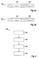
- Fig. 3a shows a data frame 300 comprising a data packet 310 and a correct checksum 320.
- the data packet 310 comprises a number of bits x.
- the checksum 320 is attached to the data packet 310 and comprises a number of bits x, whereas the checksum 320 mostly comprises a smaller number of bits x than the data packet 310 and represents a predetermined calculation of the bits of the data packet 310.
- the checksum 320 may e.g. be a CRC checksum.
- Fig. 3b correspondingly shows a data frame 300' comprising the data packet 310 and a changed or modified checksum 320', according to an embodiment of the present invention.
- the checksum 320' is attached to the data packet 310 and comprises a number of bits y, the y bits e.g. being the inverted x bits of the correct checksum of Fig. 3a .
- the bits may have been inverted according to an error signaling pattern representing the error the sender knows of.
- the receiver receives the data frame 300' comprising the actual data 310 and the modified checksum 320'.
- the receiver calculates the correct checksum out of the actual data 310 and compares it to the received checksum 320'. The result is that they are different, which means that the data 310 cannot be used. Due to the way the checksum 320' is modified, the receiver can determine that it was modified by the sender as it is improbable that the error has occurred during the data transmission.
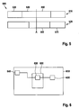
- Fig. 4 shows a flow chart of a method 400 of identifying a checksum modification as a specific error of a plurality of specific errors of an apparatus, according to an embodiment of the present invention.
- the method 400 may e.g. be executed on a receiver's side of an error signaling system on.
- a first step 410 the receiver receives a data frame from the sender, which comprises a data packet and a checksum for the data packet.
- the received checksum of the data packet needs to be verified as to whether it was modified by the sender in order to signal an error the sender knows of.
- the receiver determines a checksum from the data packet and then, in a further step 420, compares the determined checksum to the received checksum, e.g.
- the receiver identifies an error signaling pattern with which the received checksum was modified.
- the identified error signaling pattern may be listed along with other error signaling patterns in a memory unit of the receiver and corresponds to one of a plurality of specific errors each characterized by a specific error signaling pattern.
- the specific error identified may e.g. be an ASIC error or an internal device error.
- the specific error which is characterized by the error signaling pattern with which the received checksum was modified, is recognized.
- Fig. 5 shows in a combined representation 500 a command data frame 510 of a sender and a transmission or result data frame 520 of a receiver, according to an embodiment of the present invention.
- the command data frame 510 comprises a command 530, data 540 and a checksum 550.
- the result data frame 520 comprises a result 560 and a transmission checksum 570.
- the sender sends the command data frame 510 to the receiver.
- the receiver answers and starts sending the result 560 based on the data 540 to the sender.
- the receiver detects that the received data 540 does not fit to the command 530, but the sending back of the result 560 has already started.
- the receiver intentionally modifies the transmission checksum 570 with a predefined procedure.
- the sender gets direct feedback, that the current command 530 was not successful, if the sender evaluates the checksum 570 from the receiver data frame 520.
- Fig. 6 shows a control device 600 configured to perform the steps of the methods of Figs. 2 and/or 4.
- the control device 600 is shown incorporated in a vehicle 610 and comprises a sender 620.
- a receiver 630 is located at another position in the vehicle 610.
- the sender 620 is the controller of one of the vehicle's 610 sensors 640 and is aware of a specific error of the sensor 640 or through the knowledge of an internal error.
- the sender 620 first modifies a checksum of a received data packet to be transmitted to the receiver according to the above method of checksum modification.
- the sender 620 sends the data packet comprising the modified checksum to the receiver 630 via an appropriate interface.
- the receiver 630 receives the data packet comprising the modified checksum and recognizes the specific error of the sensor 640 according to the above method of identifying a checksum modification as a specific error.
- the inventive methods 200, 400 and control device 600 as described in context with Figs. 2 to 6 concern the following inventive aspects.
- the checksum 320 is intentionally modified to a wrong checksum 320', 550 to signal an error.
- this procedure it is possible to make the transmitted values or data 310, 540 invalid. But it cannot be distinguished, if the checksum 320 was intentionally modified by the sender or if it the data 310, 540 or checksum 320 was modified by disturbance.
- this procedure can be extended if both the sender 620 and the receiver 630 know how the checksum 320 is modified. Then the receiver 630 has a high probability to distinguish, if the checksum 320 was modified intentionally.
- this procedure can be extended if the sender 620 uses different procedures to modify the checksum 320 for different errors.
- checksum XOR with 0101 b could mean "internal ASIC error”
- checksum XOR with 1010b could mean "mechanical defect of sensor”
- the receiver 630 can then differentiate the reason with a high probability.
- the error signaling patterns 0101 b or 1010b may be binary numbers with which the correct checksum is modified by the application of an XOR-operation of the correct checksum by the respective error signaling pattern.
- the methods 200, 400 and control device 600 described herein may be used in environments where real disturbances are quite unlikely or are known not to produce a modified checksum, which signals an error. For example, disturbances will effect three bits at most, whereas each intentional error code will effect five bits. Otherwise there would be the possibility that a disturbance generates a valid error code.
Landscapes
- Engineering & Computer Science (AREA)
- Computer Networks & Wireless Communication (AREA)
- Signal Processing (AREA)
- Detection And Prevention Of Errors In Transmission (AREA)
Description
- The present invention relates to a method of checksum modification for signaling a specific error of a plurality of specific errors of an apparatus, a method of identifying a checksum modification as a specific error of a plurality of specific errors of an apparatus, a control device according as well as a computer program product according to the independent claims.
- In communication environments where external disturbance, e.g. electromagnetic coupling on the communication channel, is expected, the actual data is expanded by a checksum, e.g. CRC (CRC = Cyclic Redundancy Check). The receiver knows how the sender calculated the checksum and can do the same on the current data to make sure with a high probability that the data was not changed due to external disturbance.
-
JP 7321809 -
JP 09162752 A -
GB 2 116 403 A - On this background, the present invention serves to present a method of checksum modification for signaling a specific error of a plurality of specific errors of an apparatus, a method of identifying a checksum modification as a specific error of a plurality of specific errors of an apparatus, furthermore a control device employing these methods as well as finally a respective computer program product according to the independent claims. Advantageous embodiments result from the respective dependent claims and the subsequent description.
- The present invention provides a method of checksum modification for signaling a specific error of a plurality of specific errors of an apparatus, comprising: receiving a data frame comprising a data packet and a checksum for the data packet; modifying the checksum according to one of a plurality of error signaling patterns each describing a different specific error; replacing the checksum by the modified checksum; and outputting the data frame comprising the data packet and the modified checksum.
- The method proposed herein may be employed for the communication of an error in environments where a data change due to an external disturbance is very unlikely to occur. It may e.g. be employed for the communication of an internal error of an apparatus of a vehicle, wherein the apparatus or a controller thereof may serve as the sender in a communication system for communicating the error. The apparatus may e.g. be a sensor of the vehicle, which is designed to collect data used for further processing in e.g. the vehicle's control device. The checksum may be a CRC (cyclic redundancy check) checksum, e.g. an even parity checksum. The modification may e.g. be effected by altering one or more bits of the checksum from 0 to 1 or vice versa. The signaling may be effected via an appropriate interface between e.g. a sensor controller of a vehicle and the vehicle's central control device. The specific error may be a malfunction of the apparatus that the apparatus itself or a control device of the apparatus has detected. The specific error may be such that data acquired by the respective apparatus is unreliable or faulty and should therefore not be used for further procedures. The receiving of the data frame may be effected via an appropriate interface. The data frame may e.g. contain measurement data of the vehicle's apparatus such as a sensor. Each of the plurality of error signaling patterns may differ from one another and be uniquely ascribable to one of the different specific errors. The checksum may be replaced by the modified checksum according to an appropriate algorithm. The data frame comprising the modified checksum may be output to a transmitting unit of the apparatus' controller via an appropriate interface in order to be transmitted to the control device, where further actions may be initiated depending on the data frame with the modified checksum received.
- A lot of communication protocols add CRC checksums to the actual data to detect errors during the transmission.
- The present invention is based on the finding that, if those errors are unlikely, the protocol can be expanded to transmit error codes within the CRC checksum. If the data is of no value, the checksum may be intentionally modified to a wrong checksum to signal an error.
- One major advantage of the approach presented here is that errors can be signaled even if they happen during the transmission without usage of special error bits or codes which take valuable transmission space (e.g. usage of the last three bits before the checksum to signal errors).
- According to an embodiment, in the step of modifying, the checksum may be modified by inverting at least one bit of the checksum. Depending on the modifying algorithm used, it is also possible that all bits or bits at specific positions in the checksum be inverted. Advantageously, the inversion, especially of one bit, is a quick and simple operation.
- According to a further embodiment, in the step of modifying, an XOR operation rule may be used. This kind of operation is advantageous in that it is very simple in computing.
- Furthermore, in the step of modifying, a first error signaling pattern may be used for signaling a first specific error and a second error signaling pattern may used for signaling a second specific error. Herein, the first and second signaling patterns may differ in each position of the patterns. This provides the benefit that the codes formed by the patterns will differ greatly from one another so that e.g. a very robust differentiation between a mechanical defect and an ASIC error of the apparatus in question is made possible if both errors are identified by individual error codes.
- The present invention further provides a method of identifying a checksum modification as a specific error of a plurality of specific errors of an apparatus, comprising: receiving a data frame comprising a data packet and a checksum for the data packet; comparing the received checksum to a checksum determined from the data packet in order to verify whether the received checksum was modified; in the case the received checksum was modified, identifying an error signaling pattern with which the received checksum was modified, the error signaling pattern corresponding to one of a plurality of specific errors; and recognizing the specific error corresponding to the error signaling pattern with which the received checksum was modified.
- The above method may e.g. be used for the identification of a checksum modification effected as described above. The method may be employed in a control device of a vehicle in order to acknowledge the signaling of the malfunctioning of the apparatus in question by means of the method discussed above. The control device may serve as the receiver of the communication system for communicating an error as mentioned in context with the method above. Upon the acknowledgement, a decision routine may be started in the control device in order to deactivate the faulty apparatus and inform the vehicle's driver on the malfunction and deactivation. The receiving of the data frame may be effected via an appropriate interface between a controller of the apparatus and the control device. The data frame may be the data frame as discussed above in context with the method of checksum modification. The steps of comparing and determining may be performed using appropriate algorithms. The verification of the checksum having been modified may be made in that the comparison shows that the checksum received differs from the checksum in a certain manner, wherein the certain manner may indicate the error signaling pattern. The specific error may be recognized by comparing the error signaling pattern with e.g. a table of specific errors and corresponding error signaling patterns by an appropriate comparison algorithm.
- According to an embodiment, the method may further comprise a step of invalidating the data packet for further usage if, in the step of comparing, it is determined that the received checksum was modified. The invalidation of the data packet may bear the advantage that it may be prevented that erroneous data may lead to a malfunctioning of one of the vehicle's systems such as the safety system.
- The method may further comprise a step of modifying a transmission checksum of a transmission frame, which may comprise a transmission packet and a transmission checksum for the transmission packet, according to a specific modification rule, if, in the step of comparing, it was recognized that the received checksum was modified. The method may further comprise a step of outputting the transmission frame, which may comprise the transmission packet and the modified transmission checksum.
- The transmission frame may be a data frame to be sent from the receiver to the sender in response to the data frame received from the sender. The modifying of the transmission checksum may be effected in analogy to the above discussed method of checksum modification. The outputting may be effected via an interface between the receiver and the sender. The advantage of this step may be that the receiver may in this way notify the sender of the acknowledgement of the specific error.
- The present invention further provides a control device configured to effect or implement the steps of the inventive methods. Especially the control device may comprise means; each means being configured for performing one of the steps of one of the inventive methods. This alternative embodiment of the invention in the form of a control device may also serve to achieve the object underlying the invention in a fast and efficient manner.
- At hand, a control device may be an electric device, which processes sensor signals and, in dependence thereon, outputs control signals. The control device may comprise an interface, which may be configured in hardware and/or in software. In the case of a configuration in hardware, these interfaces may, for example, be part of a so-called system ASIC, which comprises diverse functions of the control device. However, it is also possible that the interfaces be individual, integrated circuits or at least partially consist of discrete components. In the case of a configuration in software, the interfaces may be software modules, which may be provided on a microcontroller next to other software modules, for example.
- What is also advantageous is a computer program product with a program code stored on a machine-readable carrier such as a semiconductor memory, a hard disk or an optical memory and utilized for performing the method according to any one of the aforementioned embodiments, when the program is executed on a control device.
- The invention is exemplarily explained in further detail by means of the accompanying drawings, in which:
- Fig. 1
- shows a representation of how an external disturbance changes actual data in data transmission;
- Fig. 2
- shows a flow chart of a method of checksum modification for signaling a specific error, according to an embodiment of the present invention;
- Fig. 3a
- shows a data frame comprising a data packet and a correct check-sum;
- Fig. 3b
- shows a data frame comprising a data packet and a modified check-sum, according to an embodiment of the present invention
- Fig. 4
- shows a flow chart of a method of identifying a checksum modification as a specific error, according to an embodiment of the present invention;
- Fig. 5
- shows in a combined representation a command data frame of a sender and a result data frame of a receiver, according to an embodiment of the present invention; and
- Fig. 6
- shows a control device configured to perform the steps of one of the methods of
Figs. 2 and4 . - In the figures, like or similar elements may be provided with like or similar reference numbers, with a repeated description being dispensed with. In addition, the figures of the drawings, the description thereof as well as the claims include numerous features in combination. A person skilled in the art clearly understands that these features may also be regarded individually or that they may be combined to form further combinations that are not explicitly described herein. Furthermore, the invention may in the following description be discussed using different measures and dimensions, whereby stating these measures and dimensions is not to be understood such that the invention is to be understood as limited to these measures and dimensions. Furthermore, inventive method steps may also be executed repeatedly or in an order other than described. If an embodiment includes an "and/or" connection between a first feature and a second feature, this may be interpreted such that the embodiment may, according to one form, comprise both the first feature and a second feature and, according to another form, comprise the first feature only or the second feature only.
- In order to explain the present invention reference is firstly made to a general concept of checksum verification used in data transmissions.
Fig. 1 shows a representation of how external disturbance changes actual data in data transmission. A sender sends adata frame 100 comprisingactual data 110 and achecksum 120 to a receiver. During transmission,external disturbance 130 changes theactual data 110. The receiver receives adata frame 100' comprising actual data 110' and thechecksum 120. The receiver calculates the checksum of the received actual data 110' and detects that it does not match the receivedchecksum 120. Thus, due to the detected mismatch, an error in the transmission is recognized and as a consequence, an error handling procedure is started. - In the following figures, the communication between a sender and a receiver depends on the protocol used. It could either be a master-slave communication with immediate response (in-frame) or response during the next communication (off-frame), or it could be an asynchronous communication, like e.g. Ethernet. The inventive approach can be used in all environments.
-
Fig. 2 shows a flow chart of amethod 200 of checksum modification for signaling a specific error of a plurality of specific errors of an apparatus, according to an embodiment of the present invention. Themethod 200 may e.g. be executed in an error signaling system comprising a sender sending a data frame and a receiver receiving the data frame. In afirst step 210, the sender, which may e.g. be a controller of the apparatus, loads a data frame comprising a data packet and a checksum for the data packet. The checksum may e.g. be a CRC checksum serving as a verification of the data packet. Further, the sender has information about a specific error, e.g. a mechanical defect of the apparatus, i.e. the sender, or an internal ASIC error, such that the data packet should not be used in any further calculations due to possible errors in the data packet. In asecond step 220, the sender or a specific unit of the sender modifies the checksum according to one of a plurality of error signaling patterns. Each one of the plurality of error signaling patterns may describe a different specific error and may e.g. be stored in a database, which may be accessed by the sender of the sender's unit according to the present error . In a followingstep 230, the original checksum is replaced by the checksum modified according to the specific error signaling pattern. And in astep 240, data frame comprising the data packet and the modified checksum is output by the sender via an appropriate interface. Thus, a receiver, which may e.g. be a vehicle's control device, may receive the data frame comprising the data packet and the modified checksum from the sender. -
Fig. 3a shows adata frame 300 comprising adata packet 310 and acorrect checksum 320. Thedata packet 310 comprises a number of bits x. Thechecksum 320 is attached to thedata packet 310 and comprises a number of bits x, whereas thechecksum 320 mostly comprises a smaller number of bits x than thedata packet 310 and represents a predetermined calculation of the bits of thedata packet 310. Thechecksum 320 may e.g. be a CRC checksum. First, the sender prepares thedata frame 300 comprising theactual data 310 and thecorrect checksum 320. The sender knows of some internal error and wants to prevent the receiver to use thedata 310. Therefore, thecorrect checksum 320 is changed by e.g. inverting all or distinct bits. Then the information, i.e. the data frame, is sent out. -
Fig. 3b correspondingly shows a data frame 300' comprising thedata packet 310 and a changed or modified checksum 320', according to an embodiment of the present invention. The checksum 320' is attached to thedata packet 310 and comprises a number of bits y, the y bits e.g. being the inverted x bits of the correct checksum ofFig. 3a . The bits may have been inverted according to an error signaling pattern representing the error the sender knows of. The receiver receives the data frame 300' comprising theactual data 310 and the modified checksum 320'. The receiver calculates the correct checksum out of theactual data 310 and compares it to the received checksum 320'. The result is that they are different, which means that thedata 310 cannot be used. Due to the way the checksum 320' is modified, the receiver can determine that it was modified by the sender as it is improbable that the error has occurred during the data transmission. -
Fig. 4 shows a flow chart of amethod 400 of identifying a checksum modification as a specific error of a plurality of specific errors of an apparatus, according to an embodiment of the present invention. Themethod 400 may e.g. be executed on a receiver's side of an error signaling system on. In afirst step 410, the receiver receives a data frame from the sender, which comprises a data packet and a checksum for the data packet. The received checksum of the data packet needs to be verified as to whether it was modified by the sender in order to signal an error the sender knows of. In order to achieve this, first the receiver determines a checksum from the data packet and then, in afurther step 420, compares the determined checksum to the received checksum, e.g. by using an appropriate algorithm. If the comparison shows that the determined checksum differs from the received checksum, a conclusion is made that the received checksum was modified. In a followingstep 430, the receiver identifies an error signaling pattern with which the received checksum was modified. The identified error signaling pattern may be listed along with other error signaling patterns in a memory unit of the receiver and corresponds to one of a plurality of specific errors each characterized by a specific error signaling pattern. The specific error identified may e.g. be an ASIC error or an internal device error. Finally, in astep 440, the specific error, which is characterized by the error signaling pattern with which the received checksum was modified, is recognized. -
Fig. 5 shows in a combined representation 500 acommand data frame 510 of a sender and a transmission or resultdata frame 520 of a receiver, according to an embodiment of the present invention. Thecommand data frame 510 comprises acommand 530,data 540 and achecksum 550. Theresult data frame 520 comprises aresult 560 and atransmission checksum 570. The sender sends thecommand data frame 510 to the receiver. At a time A, when the receiver has received thedata 540 but not yet thechecksum 550, the receiver answers and starts sending theresult 560 based on thedata 540 to the sender. At time A, the receiver detects that the receiveddata 540 does not fit to thecommand 530, but the sending back of theresult 560 has already started. To signal that, for one thing, thecommand 530 anddata 540 do not fit together and, for another thing, theresult 560 is worthless, the receiver intentionally modifies thetransmission checksum 570 with a predefined procedure. The sender gets direct feedback, that thecurrent command 530 was not successful, if the sender evaluates thechecksum 570 from thereceiver data frame 520. -
Fig. 6 shows acontrol device 600 configured to perform the steps of the methods ofFigs. 2 and/or 4. InFig. 6 , thecontrol device 600 is shown incorporated in avehicle 610 and comprises asender 620. Further, areceiver 630 is located at another position in thevehicle 610. In the exemplary illustration shown inFig. 6 , thesender 620 is the controller of one of the vehicle's 610sensors 640 and is aware of a specific error of thesensor 640 or through the knowledge of an internal error. In order to signal the specific error to thereceiver 630, thesender 620 first modifies a checksum of a received data packet to be transmitted to the receiver according to the above method of checksum modification. Then, thesender 620 sends the data packet comprising the modified checksum to thereceiver 630 via an appropriate interface. Thereceiver 630 receives the data packet comprising the modified checksum and recognizes the specific error of thesensor 640 according to the above method of identifying a checksum modification as a specific error. - To sum up, the
inventive methods control device 600 as described in context withFigs. 2 to 6 concern the following inventive aspects. Firstly, thechecksum 320 is intentionally modified to awrong checksum 320', 550 to signal an error. Using this procedure, it is possible to make the transmitted values ordata checksum 320 was intentionally modified by the sender or if it thedata checksum 320 was modified by disturbance. Secondly, this procedure can be extended if both thesender 620 and thereceiver 630 know how thechecksum 320 is modified. Then thereceiver 630 has a high probability to distinguish, if thechecksum 320 was modified intentionally. Now it is possible to distinguish between a transmission disturbance and an error at thesender 620 side. Thirdly, this procedure can be extended if thesender 620 uses different procedures to modify thechecksum 320 for different errors. For example, checksum XOR with 0101 b could mean "internal ASIC error"; checksum XOR with 1010b could mean "mechanical defect of sensor"; etc. Thereceiver 630 can then differentiate the reason with a high probability. Thus, the error signaling patterns 0101 b or 1010b may be binary numbers with which the correct checksum is modified by the application of an XOR-operation of the correct checksum by the respective error signaling pattern. - The
methods control device 600 described herein may be used in environments where real disturbances are quite unlikely or are known not to produce a modified checksum, which signals an error. For example, disturbances will effect three bits at most, whereas each intentional error code will effect five bits. Otherwise there would be the possibility that a disturbance generates a valid error code.
Claims (7)
- Method (200) of checksum modification for signaling a specific error of a plurality of specific errors of an apparatus, comprising:receiving (210) a data frame (300) comprising a data packet (310) and a checksum (320) for the data packet;modifying (220) the checksum according to one of a plurality of error signaling patterns each describing a different specific error, wherein a first error signaling pattern is used for signaling a first specific error and a second error signaling pattern is used for signaling a second specific error, the first and second signaling patterns differing in each position of the patterns;replacing (230) the checksum by the modified checksum (320'; 550); andoutputting (240) the data frame comprising the data packet and the modified checksum.
- Method (200) of claim 1, wherein, in the step of modifying (220), the checksum (320) is modified by inverting at least one bit (x) of the checksum, especially wherein in the step of modifying (220), the checksum is modified by inverting at least two bits of the checksum.
- Method (200) of claim 2, wherein, in the step of modifying (220), an XOR operation rule is used.
- Method (400) of identifying a checksum modification as a specific error of a plurality of specific errors of an apparatus, comprising:receiving (410) a data frame (300'; 510) comprising a data packet (310; 540) and a checksum (320'; 550) for the data packet;comparing (420) the received checksum to a checksum determined from the data packet in order to verify whether the received checksum was modified;in the case the received checksum was modified, identifying (430) an error signaling pattern with which the received checksum was modified, the error signaling pattern corresponding to one of a plurality of specific errors; wherein a first error signaling pattern is used for signaling a first specific error and a second error signaling pattern is used for signaling a second specific error, the first and second signaling patterns differing in each position of the patterns;recognizing (440) the specific error corresponding to the error signaling pattern with which the received checksum was modified; andinvalidating the data packet (310; 540) for further usage if, in the step of comparing, it is determined that the received checksum (320'; 550) was modified.
- Method (400) of claim 4, further comprising a step of modifying a transmission checksum (570) of a transmission frame (520) comprising a transmission packet (560) and the transmission checksum for the transmission packet according to a specific modification rule if, in the step of comparing, it was recognized that the received checksum (320'; 550) was modified, and further comprising a step of outputting the transmission frame comprising the transmission packet and the modified transmission checksum.
- Control device (600) configured to perform the steps of a method (100; 400) according to any one of claims 1 to 5.
- Computer program product with a program code stored on a machine-readable carrier, for performing a method (100; 400) of any one of claims 1 to 5, when the program is executed on a control device.
Priority Applications (1)
| Application Number | Priority Date | Filing Date | Title |
|---|---|---|---|
| EP20100166961 EP2400682B1 (en) | 2010-06-23 | 2010-06-23 | Method and device for a checksum modification and identifying a checksum modification |
Applications Claiming Priority (1)
| Application Number | Priority Date | Filing Date | Title |
|---|---|---|---|
| EP20100166961 EP2400682B1 (en) | 2010-06-23 | 2010-06-23 | Method and device for a checksum modification and identifying a checksum modification |
Publications (2)
| Publication Number | Publication Date |
|---|---|
| EP2400682A1 EP2400682A1 (en) | 2011-12-28 |
| EP2400682B1 true EP2400682B1 (en) | 2013-04-17 |
Family
ID=42558547
Family Applications (1)
| Application Number | Title | Priority Date | Filing Date |
|---|---|---|---|
| EP20100166961 Not-in-force EP2400682B1 (en) | 2010-06-23 | 2010-06-23 | Method and device for a checksum modification and identifying a checksum modification |
Country Status (1)
| Country | Link |
|---|---|
| EP (1) | EP2400682B1 (en) |
Families Citing this family (16)
| Publication number | Priority date | Publication date | Assignee | Title |
|---|---|---|---|---|
| CN103856288B (en) * | 2012-12-04 | 2017-06-06 | 北汽福田汽车股份有限公司 | For the CAN communication signal checking and transmission method and system of automobile |
| CN104836832A (en) * | 2014-12-10 | 2015-08-12 | 北汽福田汽车股份有限公司 | Vehicle CAN signal transmission safety and verification method |
| JP6576185B2 (en) * | 2015-09-24 | 2019-09-18 | ローム株式会社 | Image data transmission circuit, electronic device using the same, and image data transmission system |
| EP3166246B1 (en) * | 2015-11-06 | 2018-06-20 | Fts Computertechnik Gmbh | Method to detect and to handle failures in the communication in a computer network |
| US12198605B2 (en) | 2019-03-29 | 2025-01-14 | Creeled, Inc. | Active control of light emitting diodes and light emitting diode displays |
| US12142716B2 (en) | 2019-03-29 | 2024-11-12 | Creeled, Inc. | Active control of light emitting diodes and light emitting diode displays |
| US11727857B2 (en) | 2019-03-29 | 2023-08-15 | Creeled, Inc. | Active control of light emitting diodes and light emitting diode displays |
| US11694601B2 (en) | 2019-03-29 | 2023-07-04 | Creeled, Inc. | Active control of light emitting diodes and light emitting diode displays |
| DE102019125693A1 (en) | 2019-09-24 | 2021-03-25 | Beckhoff Automation Gmbh | Method for operating a communication network, communication network and subscriber for a communication network |
| WO2023088782A1 (en) * | 2021-11-19 | 2023-05-25 | Biotronik Se & Co. Kg | Computer implemented method and system for protecting a patient critical firmware function of an implantable medical device |
| WO2023150502A1 (en) | 2022-02-07 | 2023-08-10 | Creeled, Inc. | Light-emitting diodes with mixed clock domain signaling |
| US12014673B2 (en) | 2022-02-07 | 2024-06-18 | Creeled, Inc. | Light-emitting diodes with mixed clock domain signaling |
| US12618917B2 (en) | 2022-11-15 | 2026-05-05 | Creeled, Inc. | Error detection in LED packages |
| US12014677B1 (en) | 2023-04-10 | 2024-06-18 | Creeled, Inc. | Light-emitting diode packages with transformation and shifting of pulse width modulation signals and related methods |
| US12526889B2 (en) | 2023-08-29 | 2026-01-13 | Creeled, Inc. | Light-emitting diode packages with varying current pulse width modulation and related methods |
| US12437707B2 (en) | 2023-09-27 | 2025-10-07 | Creeled, Inc. | Pseudo-exponential encoding for light-emitting devices and related methods |
Family Cites Families (4)
| Publication number | Priority date | Publication date | Assignee | Title |
|---|---|---|---|---|
| US3836957A (en) * | 1973-06-26 | 1974-09-17 | Ibm | Data storage system with deferred error detection |
| GB2116403B (en) * | 1982-03-01 | 1985-10-23 | British Broadcasting Corp | Improvements relating to digital data transmission |
| JPH07321809A (en) | 1994-05-27 | 1995-12-08 | Toshiba Micro Comput Eng Corp | ATM cell conversion device |
| JP3252681B2 (en) * | 1995-12-04 | 2002-02-04 | 日本ビクター株式会社 | Digital data output device |
-
2010
- 2010-06-23 EP EP20100166961 patent/EP2400682B1/en not_active Not-in-force
Also Published As
| Publication number | Publication date |
|---|---|
| EP2400682A1 (en) | 2011-12-28 |
Similar Documents
| Publication | Publication Date | Title |
|---|---|---|
| EP2400682A1 (en) | Method and device for a checksum modification and identifying a checksum modification | |
| US11108499B2 (en) | System and method for transferring data and a data check field | |
| US9602894B2 (en) | Protected transmission of independent sensor signals | |
| US8799738B2 (en) | Method of detecting data transmission errors in a CAN controller, and a CAN controller for carrying out the method | |
| US8762788B2 (en) | Redundancy control system and method of transmitting computational data thereof for detection of transmission errors and failure diagnosis | |
| CN105373441B (en) | Transmission control checking for interconnect circuits | |
| US10404717B2 (en) | Method and device for the protection of data integrity through an embedded system having a main processor core and a security hardware module | |
| CN103797467A (en) | Method for operating communication network, and network arrangement | |
| US11500715B1 (en) | Determining functional safety state using software-based ternary state translation of analog input | |
| TWI518500B (en) | Data transmission detecing device, data transmission detecing method and electronic device thereof | |
| US20220382243A1 (en) | Switching between safety and non-safety states using a remote controller while ensuring functional safety requirement satisfaction | |
| US6507760B1 (en) | Numerical control unit with a spatially separated input device | |
| CN107111931A (en) | Inspection equipment for data prediction device | |
| CN114968654A (en) | A kind of error correction code circuit and error correction method | |
| US20220382238A1 (en) | Hardware implementation for detecting functional safety states using ternary state translation | |
| US20220382239A1 (en) | Ensuring Functional Safety Requirement Satisfaction For Ouput Determination and Output of Safety Messages | |
| US20080125919A1 (en) | Communication system and electronic control unit including communication system for vehicle control | |
| US12530251B2 (en) | Determining functional safety state using software-based ternary state translation of analog input | |
| US7418647B2 (en) | Method for data transmission | |
| JP2013526225A (en) | Method and apparatus for protecting data packets transmitted over an interface | |
| CN113722770B (en) | End-to-end protection method and system based on hierarchical data integrity | |
| JP4954249B2 (en) | Electronic terminal device and electronic interlocking device | |
| JP5589995B2 (en) | Information processing device | |
| IL297685A (en) | Method and safety-oriented system for performing safety functions | |
| CN101385001B (en) | Apparatus and method for determining values of binary information delivered in a redundant manner and representing system parameters |
Legal Events
| Date | Code | Title | Description |
|---|---|---|---|
| AK | Designated contracting states |
Kind code of ref document: A1 Designated state(s): AL AT BE BG CH CY CZ DE DK EE ES FI FR GB GR HR HU IE IS IT LI LT LU LV MC MK MT NL NO PL PT RO SE SI SK SM TR |
|
| AX | Request for extension of the european patent |
Extension state: BA ME RS |
|
| PUAI | Public reference made under article 153(3) epc to a published international application that has entered the european phase |
Free format text: ORIGINAL CODE: 0009012 |
|
| 17P | Request for examination filed |
Effective date: 20120628 |
|
| 17Q | First examination report despatched |
Effective date: 20120724 |
|
| GRAP | Despatch of communication of intention to grant a patent |
Free format text: ORIGINAL CODE: EPIDOSNIGR1 |
|
| GRAS | Grant fee paid |
Free format text: ORIGINAL CODE: EPIDOSNIGR3 |
|
| GRAA | (expected) grant |
Free format text: ORIGINAL CODE: 0009210 |
|
| AK | Designated contracting states |
Kind code of ref document: B1 Designated state(s): AL AT BE BG CH CY CZ DE DK EE ES FI FR GB GR HR HU IE IS IT LI LT LU LV MC MK MT NL NO PL PT RO SE SI SK SM TR |
|
| REG | Reference to a national code |
Ref country code: GB Ref legal event code: FG4D |
|
| REG | Reference to a national code |
Ref country code: CH Ref legal event code: EP |
|
| REG | Reference to a national code |
Ref country code: IE Ref legal event code: FG4D |
|
| REG | Reference to a national code |
Ref country code: AT Ref legal event code: REF Ref document number: 607854 Country of ref document: AT Kind code of ref document: T Effective date: 20130515 |
|
| REG | Reference to a national code |
Ref country code: DE Ref legal event code: R096 Ref document number: 602010006177 Country of ref document: DE Effective date: 20130613 |
|
| REG | Reference to a national code |
Ref country code: AT Ref legal event code: MK05 Ref document number: 607854 Country of ref document: AT Kind code of ref document: T Effective date: 20130417 |
|
| REG | Reference to a national code |
Ref country code: LT Ref legal event code: MG4D |
|
| REG | Reference to a national code |
Ref country code: NL Ref legal event code: VDEP Effective date: 20130417 |
|
| PG25 | Lapsed in a contracting state [announced via postgrant information from national office to epo] |
Ref country code: LT Free format text: LAPSE BECAUSE OF FAILURE TO SUBMIT A TRANSLATION OF THE DESCRIPTION OR TO PAY THE FEE WITHIN THE PRESCRIBED TIME-LIMIT Effective date: 20130417 Ref country code: SE Free format text: LAPSE BECAUSE OF FAILURE TO SUBMIT A TRANSLATION OF THE DESCRIPTION OR TO PAY THE FEE WITHIN THE PRESCRIBED TIME-LIMIT Effective date: 20130417 Ref country code: BE Free format text: LAPSE BECAUSE OF FAILURE TO SUBMIT A TRANSLATION OF THE DESCRIPTION OR TO PAY THE FEE WITHIN THE PRESCRIBED TIME-LIMIT Effective date: 20130417 Ref country code: FI Free format text: LAPSE BECAUSE OF FAILURE TO SUBMIT A TRANSLATION OF THE DESCRIPTION OR TO PAY THE FEE WITHIN THE PRESCRIBED TIME-LIMIT Effective date: 20130417 Ref country code: IS Free format text: LAPSE BECAUSE OF FAILURE TO SUBMIT A TRANSLATION OF THE DESCRIPTION OR TO PAY THE FEE WITHIN THE PRESCRIBED TIME-LIMIT Effective date: 20130817 Ref country code: GR Free format text: LAPSE BECAUSE OF FAILURE TO SUBMIT A TRANSLATION OF THE DESCRIPTION OR TO PAY THE FEE WITHIN THE PRESCRIBED TIME-LIMIT Effective date: 20130718 Ref country code: ES Free format text: LAPSE BECAUSE OF FAILURE TO SUBMIT A TRANSLATION OF THE DESCRIPTION OR TO PAY THE FEE WITHIN THE PRESCRIBED TIME-LIMIT Effective date: 20130728 Ref country code: AT Free format text: LAPSE BECAUSE OF FAILURE TO SUBMIT A TRANSLATION OF THE DESCRIPTION OR TO PAY THE FEE WITHIN THE PRESCRIBED TIME-LIMIT Effective date: 20130417 Ref country code: SI Free format text: LAPSE BECAUSE OF FAILURE TO SUBMIT A TRANSLATION OF THE DESCRIPTION OR TO PAY THE FEE WITHIN THE PRESCRIBED TIME-LIMIT Effective date: 20130417 Ref country code: PT Free format text: LAPSE BECAUSE OF FAILURE TO SUBMIT A TRANSLATION OF THE DESCRIPTION OR TO PAY THE FEE WITHIN THE PRESCRIBED TIME-LIMIT Effective date: 20130819 Ref country code: NO Free format text: LAPSE BECAUSE OF FAILURE TO SUBMIT A TRANSLATION OF THE DESCRIPTION OR TO PAY THE FEE WITHIN THE PRESCRIBED TIME-LIMIT Effective date: 20130717 |
|
| PG25 | Lapsed in a contracting state [announced via postgrant information from national office to epo] |
Ref country code: PL Free format text: LAPSE BECAUSE OF FAILURE TO SUBMIT A TRANSLATION OF THE DESCRIPTION OR TO PAY THE FEE WITHIN THE PRESCRIBED TIME-LIMIT Effective date: 20130417 Ref country code: BG Free format text: LAPSE BECAUSE OF FAILURE TO SUBMIT A TRANSLATION OF THE DESCRIPTION OR TO PAY THE FEE WITHIN THE PRESCRIBED TIME-LIMIT Effective date: 20130717 Ref country code: LV Free format text: LAPSE BECAUSE OF FAILURE TO SUBMIT A TRANSLATION OF THE DESCRIPTION OR TO PAY THE FEE WITHIN THE PRESCRIBED TIME-LIMIT Effective date: 20130417 Ref country code: CY Free format text: LAPSE BECAUSE OF FAILURE TO SUBMIT A TRANSLATION OF THE DESCRIPTION OR TO PAY THE FEE WITHIN THE PRESCRIBED TIME-LIMIT Effective date: 20130417 Ref country code: HR Free format text: LAPSE BECAUSE OF FAILURE TO SUBMIT A TRANSLATION OF THE DESCRIPTION OR TO PAY THE FEE WITHIN THE PRESCRIBED TIME-LIMIT Effective date: 20130417 |
|
| PG25 | Lapsed in a contracting state [announced via postgrant information from national office to epo] |
Ref country code: SK Free format text: LAPSE BECAUSE OF FAILURE TO SUBMIT A TRANSLATION OF THE DESCRIPTION OR TO PAY THE FEE WITHIN THE PRESCRIBED TIME-LIMIT Effective date: 20130417 Ref country code: MC Free format text: LAPSE BECAUSE OF FAILURE TO SUBMIT A TRANSLATION OF THE DESCRIPTION OR TO PAY THE FEE WITHIN THE PRESCRIBED TIME-LIMIT Effective date: 20130417 Ref country code: DK Free format text: LAPSE BECAUSE OF FAILURE TO SUBMIT A TRANSLATION OF THE DESCRIPTION OR TO PAY THE FEE WITHIN THE PRESCRIBED TIME-LIMIT Effective date: 20130417 Ref country code: EE Free format text: LAPSE BECAUSE OF FAILURE TO SUBMIT A TRANSLATION OF THE DESCRIPTION OR TO PAY THE FEE WITHIN THE PRESCRIBED TIME-LIMIT Effective date: 20130417 Ref country code: CZ Free format text: LAPSE BECAUSE OF FAILURE TO SUBMIT A TRANSLATION OF THE DESCRIPTION OR TO PAY THE FEE WITHIN THE PRESCRIBED TIME-LIMIT Effective date: 20130417 |
|
| PLBE | No opposition filed within time limit |
Free format text: ORIGINAL CODE: 0009261 |
|
| STAA | Information on the status of an ep patent application or granted ep patent |
Free format text: STATUS: NO OPPOSITION FILED WITHIN TIME LIMIT |
|
| PG25 | Lapsed in a contracting state [announced via postgrant information from national office to epo] |
Ref country code: IT Free format text: LAPSE BECAUSE OF FAILURE TO SUBMIT A TRANSLATION OF THE DESCRIPTION OR TO PAY THE FEE WITHIN THE PRESCRIBED TIME-LIMIT Effective date: 20130417 Ref country code: NL Free format text: LAPSE BECAUSE OF FAILURE TO SUBMIT A TRANSLATION OF THE DESCRIPTION OR TO PAY THE FEE WITHIN THE PRESCRIBED TIME-LIMIT Effective date: 20130417 Ref country code: RO Free format text: LAPSE BECAUSE OF FAILURE TO SUBMIT A TRANSLATION OF THE DESCRIPTION OR TO PAY THE FEE WITHIN THE PRESCRIBED TIME-LIMIT Effective date: 20130417 |
|
| 26N | No opposition filed |
Effective date: 20140120 |
|
| REG | Reference to a national code |
Ref country code: IE Ref legal event code: MM4A |
|
| REG | Reference to a national code |
Ref country code: FR Ref legal event code: ST Effective date: 20140228 |
|
| PG25 | Lapsed in a contracting state [announced via postgrant information from national office to epo] |
Ref country code: IE Free format text: LAPSE BECAUSE OF NON-PAYMENT OF DUE FEES Effective date: 20130623 |
|
| REG | Reference to a national code |
Ref country code: DE Ref legal event code: R097 Ref document number: 602010006177 Country of ref document: DE Effective date: 20140120 |
|
| PG25 | Lapsed in a contracting state [announced via postgrant information from national office to epo] |
Ref country code: FR Free format text: LAPSE BECAUSE OF NON-PAYMENT OF DUE FEES Effective date: 20130701 |
|
| REG | Reference to a national code |
Ref country code: CH Ref legal event code: PL |
|
| GBPC | Gb: european patent ceased through non-payment of renewal fee |
Effective date: 20140623 |
|
| PG25 | Lapsed in a contracting state [announced via postgrant information from national office to epo] |
Ref country code: MT Free format text: LAPSE BECAUSE OF FAILURE TO SUBMIT A TRANSLATION OF THE DESCRIPTION OR TO PAY THE FEE WITHIN THE PRESCRIBED TIME-LIMIT Effective date: 20130417 |
|
| PG25 | Lapsed in a contracting state [announced via postgrant information from national office to epo] |
Ref country code: CH Free format text: LAPSE BECAUSE OF NON-PAYMENT OF DUE FEES Effective date: 20140630 Ref country code: LI Free format text: LAPSE BECAUSE OF NON-PAYMENT OF DUE FEES Effective date: 20140630 |
|
| PG25 | Lapsed in a contracting state [announced via postgrant information from national office to epo] |
Ref country code: SM Free format text: LAPSE BECAUSE OF FAILURE TO SUBMIT A TRANSLATION OF THE DESCRIPTION OR TO PAY THE FEE WITHIN THE PRESCRIBED TIME-LIMIT Effective date: 20130417 Ref country code: GB Free format text: LAPSE BECAUSE OF NON-PAYMENT OF DUE FEES Effective date: 20140623 |
|
| PG25 | Lapsed in a contracting state [announced via postgrant information from national office to epo] |
Ref country code: TR Free format text: LAPSE BECAUSE OF FAILURE TO SUBMIT A TRANSLATION OF THE DESCRIPTION OR TO PAY THE FEE WITHIN THE PRESCRIBED TIME-LIMIT Effective date: 20130417 |
|
| PG25 | Lapsed in a contracting state [announced via postgrant information from national office to epo] |
Ref country code: LU Free format text: LAPSE BECAUSE OF NON-PAYMENT OF DUE FEES Effective date: 20130623 Ref country code: MK Free format text: LAPSE BECAUSE OF FAILURE TO SUBMIT A TRANSLATION OF THE DESCRIPTION OR TO PAY THE FEE WITHIN THE PRESCRIBED TIME-LIMIT Effective date: 20130417 Ref country code: HU Free format text: LAPSE BECAUSE OF FAILURE TO SUBMIT A TRANSLATION OF THE DESCRIPTION OR TO PAY THE FEE WITHIN THE PRESCRIBED TIME-LIMIT; INVALID AB INITIO Effective date: 20100623 |
|
| REG | Reference to a national code |
Ref country code: DE Ref legal event code: R084 Ref document number: 602010006177 Country of ref document: DE |
|
| PG25 | Lapsed in a contracting state [announced via postgrant information from national office to epo] |
Ref country code: AL Free format text: LAPSE BECAUSE OF FAILURE TO SUBMIT A TRANSLATION OF THE DESCRIPTION OR TO PAY THE FEE WITHIN THE PRESCRIBED TIME-LIMIT Effective date: 20130417 |
|
| PGFP | Annual fee paid to national office [announced via postgrant information from national office to epo] |
Ref country code: DE Payment date: 20230817 Year of fee payment: 14 |
|
| REG | Reference to a national code |
Ref country code: DE Ref legal event code: R119 Ref document number: 602010006177 Country of ref document: DE |
|
| PG25 | Lapsed in a contracting state [announced via postgrant information from national office to epo] |
Ref country code: DE Free format text: LAPSE BECAUSE OF NON-PAYMENT OF DUE FEES Effective date: 20250101 |