EP2400668A1 - Device/power adapter assembly with data transmission by powerline communication PLC - Google Patents
Device/power adapter assembly with data transmission by powerline communication PLC Download PDFInfo
- Publication number
- EP2400668A1 EP2400668A1 EP11171174A EP11171174A EP2400668A1 EP 2400668 A1 EP2400668 A1 EP 2400668A1 EP 11171174 A EP11171174 A EP 11171174A EP 11171174 A EP11171174 A EP 11171174A EP 2400668 A1 EP2400668 A1 EP 2400668A1
- Authority
- EP
- European Patent Office
- Prior art keywords
- circuit
- voltage
- mains
- equipment
- low
- Prior art date
- Legal status (The legal status is an assumption and is not a legal conclusion. Google has not performed a legal analysis and makes no representation as to the accuracy of the status listed.)
- Granted
Links
Images


Classifications
-
- H—ELECTRICITY
- H04—ELECTRIC COMMUNICATION TECHNIQUE
- H04B—TRANSMISSION
- H04B3/00—Line transmission systems
- H04B3/54—Systems for transmission via power distribution lines
-
- H—ELECTRICITY
- H04—ELECTRIC COMMUNICATION TECHNIQUE
- H04B—TRANSMISSION
- H04B2203/00—Indexing scheme relating to line transmission systems
- H04B2203/54—Aspects of powerline communications not already covered by H04B3/54 and its subgroups
- H04B2203/5404—Methods of transmitting or receiving signals via power distribution lines
- H04B2203/5412—Methods of transmitting or receiving signals via power distribution lines by modofying wave form of the power source
-
- H—ELECTRICITY
- H04—ELECTRIC COMMUNICATION TECHNIQUE
- H04B—TRANSMISSION
- H04B2203/00—Indexing scheme relating to line transmission systems
- H04B2203/54—Aspects of powerline communications not already covered by H04B3/54 and its subgroups
- H04B2203/5429—Applications for powerline communications
- H04B2203/545—Audio/video application, e.g. interphone
-
- H—ELECTRICITY
- H04—ELECTRIC COMMUNICATION TECHNIQUE
- H04B—TRANSMISSION
- H04B2203/00—Indexing scheme relating to line transmission systems
- H04B2203/54—Aspects of powerline communications not already covered by H04B3/54 and its subgroups
- H04B2203/5429—Applications for powerline communications
- H04B2203/5458—Monitor sensor; Alarm systems
-
- H—ELECTRICITY
- H04—ELECTRIC COMMUNICATION TECHNIQUE
- H04B—TRANSMISSION
- H04B2203/00—Indexing scheme relating to line transmission systems
- H04B2203/54—Aspects of powerline communications not already covered by H04B3/54 and its subgroups
- H04B2203/5462—Systems for power line communications
- H04B2203/547—Systems for power line communications via DC power distribution
Definitions
- the invention relates to domestic multimedia equipment implementing a technique of transmitting digital data by line power, known as CPL or PLC ( Power Line Communication ).
- the EP 1 343 253 A1 and US 4,835,517A are examples of equipment using these data transmission techniques.
- the interface between the equipment and the sector is provided by a PLC module associated with each equipment.
- the PLC module needs to recover the carrier carried on the home network as input, and also to transmit this carrier.
- These signals are generally conveyed via a transformer isolating the low voltage part comprising the digital circuits and the CPL modulation / demodulation circuits of the dangerous high voltage part of the electrical network. The transmission of these signals requires two wires.
- the PLC module also needs a so-called "zero crossing detection” or ZC (Zero Crossing) synchronization information to ensure a correct sequencing of the data processing at the frequency of the AC sector (50 Hz).
- ZC Zero Crossing
- This synchronization information (“ZC signal") requires one or two additional wires.
- the CPL module uses a digital data transmission cable, generally an Ethernet type cable with appropriate connections, usually an 8-wire RJ45 plug.
- the PLC module can also integrate a low voltage supply, typically 12 V, for the equipment to which they will be associated.
- the module is also provided at the output of a power cable terminated by a plug to connect to the equipment to be powered by the remote box containing the CPL module.
- CPL package is the combined power supply / CPL module called Freeplug, manufactured by the Free Internet Service Provider, Paris, France, which is intended to power the "box" type equipment of this supplier.
- access such as Freebox (multi-function ADSL box: television, telephone, Wi-Fi router) and Freebox HD (TV box incorporating a set-top box, digital video recorder, home server, etc.).
- CPL-based data exchange is an interesting alternative to wireless transmissions (Wi-Fi network), which are not always possible because of obstacles to radio transmission, or which are not desired by the user.
- a combined power supply unit / PLC module is in the form of a housing ("mains unit") provided with input of a power cable and output of a double cord, namely a 12 V power cord, doubled by an 8-wire Ethernet type shielded cable for transmitting the demodulated data to / from the remote "box".
- mains unit provided with input of a power cable and output of a double cord, namely a 12 V power cord, doubled by an 8-wire Ethernet type shielded cable for transmitting the demodulated data to / from the remote "box".
- a CPL module produces a significant amount of heat (its power consumption is of the order of 3 watts), and it is necessary to integrate it in a block as compact as possible, moreover close to a power generating by itself a relatively large heat release. It is therefore important to study the cooling of the specific circuits of the PLC module very carefully in order to protect them from excessive temperatures that could lead to failure or, at the very least, accelerated aging.
- the invention proposes, essentially, to decoy the feedback loop providing regulation of the power converter (230 V AC to 12 V DC) by re-injecting, superimposed to the setpoint voltage of the feedback loop, a signal derived from the mains voltage.
- the slaving will interpret this as a setpoint of decrease or increase of the output voltage (when in fact it is stabilized) and respond accordingly, giving the order to decrease the output voltage when the feedback signal increases the target voltage of the feedback loop and vice versa.
- the subject of the invention is an assembly comprising the known elements, for example according to the EP 1 343 253 A1 mentioned in the preamble of claim 1.
- the elements of the invention are set forth in the characterizing part of claim 1, and the subclaims are directed to various advantageous subsidiary features.
- the invention also covers, in isolation, the power supply unit and the equipment adapted to such an assembly.
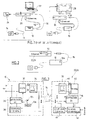
- the Figure 1 schematically illustrates two sets according to the state of the art, each comprising a power supply unit and a device connected together, typically, by a double cord.
- Each set consists of a power supply unit 10 combined low voltage power supply / PLC module, connected by a cord 12 to a socket 14 of the power line (usually 230 V - 50 Hz).
- the power supply unit 10 is provided with a cord 16 serving as a low-voltage power supply conductor (generally +12 V) and a digital data cable 18, for example an Ethernet cable, these two cords 16, 18 being connected to equipment 20 or 26.
- the equipment 20 is for example a multi-function ADSL box connected to a computer 22 and to a telephone jack 24 (for ADSL interfacing), and the equipment 26 is a TV box connected to a television 28. Thanks to the integrated CPL modules to the sector blocks 10, it is possible to exchange data between the equipment 20 placed near the telephone jack 24 and the equipment 26 placed near the television 28.
- the object of the invention is, as illustrated Figure 2 , to eliminate the cable 18 specific to the transmission of digital data between the power supply unit 10 and the equipment 20 or 26, by passing all the information necessary for the implementation of the CPL technique by the only driver of the low voltage power supply 16 of equipment 20 or 26.
- the Figure 3 illustrates in block diagram form the various circuits of the mains unit 10 and those designated 30, which are integrated in the equipment 20, 26 and which are specific to the implementation of the invention.
- the power supply unit 10 comprises a switching AC / DC converter 32 making it possible to transform the AC 230 V - 50 Hz mains voltage into a +12 V DC stabilized voltage. This DC voltage is applied to the low-voltage power supply lead 16. remote equipment 20, 26.
- the coupling between the converter 32 and the low-voltage conductor 16 is via a low-pass filter 34 consisting of a power inductance dimensioned so as to be able to withstand the output current in the low-voltage conductor (of several amperes, typically of the order of 4 A), ensuring that the power supply does not have a low impedance at high frequencies, which would attenuate the PLC signals.
- a low-pass filter 34 consisting of a power inductance dimensioned so as to be able to withstand the output current in the low-voltage conductor (of several amperes, typically of the order of 4 A), ensuring that the power supply does not have a low impedance at high frequencies, which would attenuate the PLC signals.
- the mains unit 10 also comprises, connected to the AC mains input, an additional circuit 36 for detecting the signal ZC (detection of zero crossing) as well as a coupling circuit CPL 38.
- the circuit 36 has a control output of the converter 32, specific to the implementation of the invention.
- the CPL coupling circuit 38 is connected at the output to the low-voltage conductor 16 downstream of the low-pass filter, so that the load exhibits at high frequencies an impedance sufficiently high not to attenuate the CPL signals in the 2-30 MHz band. .
- the low-voltage conductor 16 supplies the load 40 at +12 V DC with a minimum of 50 Hz ripple residual: indeed, when the equipment comprises for example a hard disk for a video recorder digital, excessive ripple would prevent correct operation of the hard disk, so it is important to master this parameter perfectly.
- the circuit 42 for modulation / demodulation CPL comprises an input / output TX / RX connected to the coupling circuit CPL 48, itself directly connected to the low-voltage conductor 16, as well as an input / output Ethernet connected to the internal digital circuits of the 20, 26.
- This circuit 42 modulation / demodulation CPL also receives a signal ZC at the mains frequency, for the synchronization and sequencing of the modulation and demodulation of digital data.
- This signal ZC is extracted by the circuit 46 which is directly connected as input to the low-voltage conductor 16.
- the Figure 4 illustrates the structure of the switching AC / DC converter 32, which in this example is a flyback topology converter , although other topologies may be used as well (such as forward, push-pull, half-bridge or full-bridge ).
- the AC voltage (230 V - 50 Hz) of the power line is first rectified by a diode bridge 50 preceded by a low-pass filter 51 (to prevent the high frequencies generated by the power supply from disturbing the signals CPL), then filtered by a capacitor 52.
- a pulse width modulation (PWM) control circuit 54 provides for the cutting of this DC voltage, which passes through the primary of a step-down transformer 56 and a switch. solid state 58 controlled by the control circuit PWM 54.
- the secondary voltage of the transformer is rectified by a diode 60 and filtered by a capacitor 62, so as to deliver a DC voltage of +12 V in this example.
- the +12 V DC voltage is filtered and regulated by a feedback loop 64.
- the output voltage is injected into a resistive divider bridge 68, 70 to give a set voltage applied to a controlled rectifier 66.
- the PWM circuit 54 for modulating the width of the switching pulses.
- An increase in the output voltage will have the effect of increasing the input current of the optocoupler 72, producing an increase in the output current of the same optocoupler. Consequently, the circuit 54 controlled by this output current will more or less switch 58, generating a more or less significant energy transfer to the secondary of the transformer 56, which allows the control of the voltage of output depending on the load.
- this circuit is modified by providing an additional circuit 36 making it possible to collect a sinusoidal signal derived from the AC voltage of the mains line.
- This sinusoidal signal is fed back to the input node A of the feedback loop 64 (between the resistors of the divider bridge 68, 70), in superposition with the reference voltage, which will have the effect of modulating the voltage across the terminals. of the resistor 70 and thus to modulate the current in the diode 66 and in the optocoupler 72.
- the control of the circuit 54 will be thus modulated at the same rate, which will produce a corresponding modulation of the output + 12 V.
- This output will therefore be in the form of a DC voltage +12 V to which will be superimposed a sinusoidal ripple induced by the reinjection of the AC voltage by the circuit 36.
- the amplitude of this ripple is chosen by an adjustment of the various components so as to have a value (i) sufficient to facilitate its extraction on the equipment side, but (ii) insufficient to risk disturbing Equipment powered by the DC voltage delivered to the equipment.
- FIGS. 5a to 5c illustrate various alternative embodiments of the additional circuit 36 for reinjection of the AC mains voltage.
- the Figure 5b illustrates another additional circuit structure 36, where the insulation is provided by two high voltage capacitors 88, 90 of low capacitive value.
- a resistor 92 and a transient suppression diode 94 protect the downstream circuit from overvoltages that may pass through the circuit.
- the divider bridge constituted by the resistors 92 and 96 acts as a voltage step-down, and the resulting alternating voltage is applied to the point A of the feedback loop, via a link capacitor 98.
- the Figure 5c illustrates yet another embodiment of the circuit 36, where the isolation is provided by an optocoupler 100.
- a diode 102 passes only the positive halfwave of the sinusoid of the mains voltage, and a divider bridge 104, 106 lowers the voltage to a value compatible with the LED of the optocoupler, the resistor 106 is chosen so as not to exceed the maximum reverse voltage allowed across this LED.
- the resistor 108 and the capacitor 110 make it possible to recover a square signal, filtered and smoothed, which is applied to the point A of the feedback loop via the link capacitor 112.
- the Figure 6 illustrates an exemplary embodiment of the synchronization circuit 46 extractor pulse, located equipment side.
- a capacitor 114 removes the DC component (12 V) present on the low-voltage conductor 16.
- the residual AC signal is amplified by the amplifier 116 and applied to a low-pass filter 118 and then to a comparator (amplifier 120) providing a shaping and outputting the signal ZC detection of the passage through zero.
- This signal ZC is in the form of a square signal at the mains network frequency, with however a constant phase shift which will be compensated by hardware or software during the decoding ensuring the synchronization of the modulator / demodulator CPL.
- the Figure 7 illustrates the circuits CPL coupling circuits 38 and 48 respectively arranged in the mains block 10 and in the circuit 30 of the equipment 20,26.
- the CPL signal in the 2-30 MHz band is carried by the low-voltage feeder 16 of the equipment, bidirectionally.
- the circuit 38 comprises a transformer 122 providing the necessary insulation between the high voltage of the mains line and the low voltage of the conductor 16.
- This transformer 122 may be a transformer with two windings, alternately coupled to the conductor low supply voltage 16 by two connecting capacitors 124, 126.
- the circuit 48 comprises an isolation transformer 128 comprising three windings, likewise alternatively coupled to the low-voltage conductor 16 via connecting capacitors 130, 132.
- the fact of deporting the CPL modulation / demodulation circuits in the equipment makes it possible to reduce the size of the mains unit 10 (i) on the one hand because of the suppression of this circuit CPL, and (ii) d on the other hand and above all, because of the reduction of thermal stresses.
- the CPL circuit no longer undergoes heating of the converter of the mains unit. As it is also placed in the equipment, it has a larger volume to dissipate the heat it produces, so that it is much easier to ensure the proper cooling of the corresponding digital circuits, thus increasing their reliability and their lifetime.
- the power supply unit may in particular be provided for this purpose with a push-button 134 ( Figure 1 ) allowing the triggering of an "all or nothing" modulation during periods when the PLC is not used.
- This "all or nothing” modulation is an OOK (On-Off Keying) modulation, "all” meaning that the alternating signal is reinjected into the feedback loop of the flyback converter 32 by the circuit 36, and "nothing” means that this reinjection is interrupted.
- OOK On-Off Keying
- all meaning that the alternating signal is reinjected into the feedback loop of the flyback converter 32 by the circuit 36
- nothing means that this reinjection is interrupted.
- This transmission of low bit rate information between the power supply unit and the equipment is performed during the "silent periods" of the CPL data, ie the periods when none of this digital data is transmitted on the driver 16.
- This function can in particular be used at power-up, for example by pressing the button 134 for the association of the CPL boxes or the reading of the memory 136.
Abstract
Description
L'invention concerne les équipements multimédia domestiques mettant en oeuvre une technique de transmission de données numériques par courants porteurs en ligne, technique dite CPL ou PLC (Power Line Communication).The invention relates to domestic multimedia equipment implementing a technique of transmitting digital data by line power, known as CPL or PLC ( Power Line Communication ).
Il s'agit d'échanger des données numériques entre plusieurs équipements d'une même habitation via un réseau filaire constitué par les lignes préexistantes d'alimentation secteur (typiquement 230 V - 50 Hz en Europe), en faisant transiter les informations d'un équipement à l'autre par modulation d'une ou plusieurs porteuses dans une bande de fréquences habituellement située dans la plage 2-30 MHz.It is a question of exchanging digital data between several equipments of the same house via a wired network constituted by the pre-existing lines of mains supply (typically 230 V - 50 Hz in Europe), by passing the information of a equipment to one another by modulating one or more carriers in a frequency band usually in the 2-30 MHz range.
Les
L'interfaçage entre l'équipement et le secteur est assuré par un module CPL associé à chaque équipement.The interface between the equipment and the sector is provided by a PLC module associated with each equipment.
Pour assurer la communication dans les deux sens (full duplex), le module CPL a besoin de récupérer en entrée la porteuse véhiculée sur le réseau domestique, et également d'émettre cette porteuse. Ces signaux sont généralement véhiculés par l'intermédiaire d'un transformateur isolant la partie basse tension comprenant les circuits numériques et les circuits de modulation/démodulation CPL de la partie haute tension, dangereuse, du réseau électrique. La transmission de ces signaux nécessite deux fils.To ensure two-way communication (full duplex), the PLC module needs to recover the carrier carried on the home network as input, and also to transmit this carrier. These signals are generally conveyed via a transformer isolating the low voltage part comprising the digital circuits and the CPL modulation / demodulation circuits of the dangerous high voltage part of the electrical network. The transmission of these signals requires two wires.
Le module CPL a également besoin d'une information de synchronisation dite "détection de passage par zéro" ou ZC (Zero Crossing) permettant d'assurer un séquencement correct du traitement des données à la fréquence du secteur alternatif (50 Hz). Cette information de synchronisation ("signal ZC") nécessite un, voire deux fils supplémentaires.The PLC module also needs a so-called "zero crossing detection" or ZC (Zero Crossing) synchronization information to ensure a correct sequencing of the data processing at the frequency of the AC sector (50 Hz). This synchronization information ("ZC signal") requires one or two additional wires.
Enfin, en sortie, le module CPL utilise un câble de transmission de données numériques, généralement un câble de type Ethernet avec une connectique appropriée, habituellement une prise RJ45 8 fils.Finally, at the output, the CPL module uses a digital data transmission cable, generally an Ethernet type cable with appropriate connections, usually an 8-wire RJ45 plug.
Le module CPL peut également intégrer une alimentation basse tension, typiquement 12 V, pour l'équipement auquel ils sera associé. Dans ce cas, le module est également pourvu en sortie d'un câble d'alimentation terminé par une prise à brancher sur l'équipement à alimenter par le boîtier déporté contenant le module CPL.The PLC module can also integrate a low voltage supply, typically 12 V, for the equipment to which they will be associated. In this case, the module is also provided at the output of a power cable terminated by a plug to connect to the equipment to be powered by the remote box containing the CPL module.
Un exemple d'un tel boîtier CPL est le bloc combiné alimentation/module CPL dénommé Freeplug, fabriqué par le fournisseur d'accès Internet Free, Paris, France, qui est destiné à alimenter les équipements de type "box" de ce fournisseur d'accès tels que Freebox (boîtier ADSL multifonction : télévision, téléphone, routeur Wi-Fi) et Freebox HD (boîtier télévision intégrant décodeur, magnétoscope numérique à disque dur, serveur domestique, etc.).An example of such a CPL package is the combined power supply / CPL module called Freeplug, manufactured by the Free Internet Service Provider, Paris, France, which is intended to power the "box" type equipment of this supplier. access such as Freebox (multi-function ADSL box: television, telephone, Wi-Fi router) and Freebox HD (TV box incorporating a set-top box, digital video recorder, home server, etc.).
Ces deux boîtiers distincts sont disposés l'un à proximité de la prise téléphonique (pour l'interfaçage ADSL), l'autre à proximité du téléviseur, et ils peuvent communiquer entre eux par courants CPL, ainsi qu'avec d'autres équipements branchés sur le même circuit électrique de l'habitation (ordinateur). L'échange de données par courants CPL est une alternative intéressante aux transmissions sans fil (réseau Wi-Fi), qui ne sont pas toujours possibles en raison des obstacles à la transmission radio, ou qui ne sont pas souhaitées par l'utilisateur.These two separate boxes are located close to the phone jack (for ADSL interfacing), the other near the TV, and they can communicate with each other by PLC currents, as well as with other connected equipment. on the same electrical circuit of the house (computer). CPL-based data exchange is an interesting alternative to wireless transmissions (Wi-Fi network), which are not always possible because of obstacles to radio transmission, or which are not desired by the user.
Concrètement, un bloc combiné alimentation/module CPL se présente sous forme d'un boîtier ("bloc secteur") muni en entrée d'un câble secteur et en sortie d'un double cordon, à savoir un cordon d'alimentation 12 V, doublé par un cordon blindé de type Ethernet 8 fils pour la transmission des données démodulées vers/depuis la "box" distante.Specifically, a combined power supply unit / PLC module is in the form of a housing ("mains unit") provided with input of a power cable and output of a double cord, namely a 12 V power cord, doubled by an 8-wire Ethernet type shielded cable for transmitting the demodulated data to / from the remote "box".
Ce double câblage rend l'installation malcommode dans la mesure où le câble Ethernet, plus épais, est volumineux et moins flexible que le câble d'alimentation basse tension. De plus, le câble Ethernet et sa connectique associée génèrent un surcoût ainsi que des risques de rupture de liaison notamment au niveau des connecteurs RJ45, relativement fragiles.This double wiring makes installation cumbersome because the thicker Ethernet cable is bulky and less flexible than the low-voltage power cable. In addition, the Ethernet cable and its associated connectors generate additional cost as well as risks of connection break especially at RJ45 connectors, relatively fragile.
Enfin, l'intégration dans un même bloc de l'alimentation et du module CPL engendre des contraintes thermiques relativement sévères.Finally, the integration in the same block of the power supply and the PLC module generates relatively severe thermal constraints.
En effet, un module CPL produit un dégagement de chaleur non négligeable (sa puissance consommée est de l'ordre de 3 watts), et il est nécessaire de l'intégrer dans un bloc le plus compact possible, au surplus à proximité d'une alimentation générant par elle-même un dégagement de chaleur relativement important. Il convient donc d'étudier très soigneusement le refroidissement des circuits spécifiques du module CPL pour les préserver des températures excessives risquant de conduire à une défaillance ou, à tout le moins, à un vieillissement accéléré.Indeed, a CPL module produces a significant amount of heat (its power consumption is of the order of 3 watts), and it is necessary to integrate it in a block as compact as possible, moreover close to a power generating by itself a relatively large heat release. It is therefore important to study the cooling of the specific circuits of the PLC module very carefully in order to protect them from excessive temperatures that could lead to failure or, at the very least, accelerated aging.
Le but de l'invention est de proposer un ensemble dans lequel ces circuits CPL spécifiques sont déportés dans l'équipement distant au lieu d'être intégrés au bloc secteur, de manière à :
- se passer de câble de transmission de données numériques entre le bloc secteur et l'équipement ;
- diminuer la taille du bloc secteur, du fait de l'absence de circuits CPL spécifiques et surtout des contraintes thermiques moindres ;
- assurer un refroidissement efficace des circuits CPL spécifiques en logeant ceux-ci dans l'équipement, où le dégagement de chaleur locale est moindre et le volume disponible est plus important.
- do not need a digital data cable between the power supply and the equipment;
- reduce the size of the power supply unit, because of the absence of specific PLC circuits and especially the lower thermal constraints;
- ensure efficient cooling of specific PLC circuits by housing them in the equipment, where the local heat generation is less and the available volume is greater.
Mais pour ce faire, il est nécessaire de transférer à l'équipement :
- la modulation CPL dans le spectre 2-30 MHz,
- le signal de détection de passage par zéro (signal ZC) de la sinusoïde du réseau secteur, et
- la tension continue (12 V) pour l'alimentation de l'équipement connecté. Compte tenu de la puissance délivrée par l'alimentation, le courant d'alimentation atteint généralement plusieurs ampères, ce qui impose pour l'alimentation basse tension une ligne à faible impédance.
- CPL modulation in the 2-30 MHz spectrum,
- the zero crossing detection signal (signal ZC) of the sinusoid of the mains network, and
- the DC voltage (12 V) for powering the connected equipment. Given the power delivered by the power supply, the supply current generally reaches several amperes, which imposes for the low voltage supply a low impedance line.
La transmission directe du signal ZC, dont la fréquence est basse (50 Hz), n'est pas possible sur une ligne à faible impédance car l'alimentation étant conçue pour fournir une tension de sortie stable, elle s'opposera par nature à toute modification de la tension fournie à l'équipement : le signal ZC à 50 Hz serait en effet interprété comme une ondulation résiduelle, qui serait immédiatement effacée par l'asservissement de tension de l'alimentation.
enfin, l'injection directe du signal CPL (dans le spectre 2-30 MHz) sur la ligne à basse impédance entraînerait une dégradation rapide du signal entre la ligne secteur et l'équipement.Direct transmission of the low frequency (50 Hz) ZC signal is not possible on a low impedance line because the power supply being designed to provide a stable output voltage, it will be inherently modification of the voltage supplied to the equipment: the signal ZC at 50 Hz would indeed be interpreted as a residual ripple, which would be immediately erased by the voltage control of the power supply.
finally, the direct injection of the CPL signal (in the 2-30 MHz spectrum) on the low impedance line would result in a rapid degradation of the signal between the mains line and the equipment.
Le simple déport des circuits CPL du bloc secteur vers l'équipement ne permet donc pas d'atteindre à lui seul le but recherché, sauf à intégrer l'ensemble du bloc secteur à l'équipement.The simple shift of the CPL circuits from the power supply unit to the equipment does not therefore achieve the desired purpose by itself, except to integrate the entire power supply unit to the equipment.
Or on souhaite bien entendu conserver tous les avantages d'un bloc secteur séparé : réduction de la taille de l'équipement et du dégagement de chaleur au sein de cet équipement, modularité, sécurité du fait de l'absence de circuit sous tension secteur dans l'équipement, etc.However, we naturally wish to preserve all the advantages of a separate power supply unit: reduction in the size of the equipment and the release of heat within this equipment, modularity, safety due to the absence of mains voltage circuit in equipment, etc.
Pour résoudre ce problème et atteindre le but recherché, l'invention propose, essentiellement, de leurrer la boucle de contre-réaction assurant la régulation du convertisseur d'alimentation (230 V secteur alternatif vers 12 V continu) en réinjectant, en superposition à la tension de consigne de la boucle de contre-réaction, un signal dérivé de la tension secteur. L'asservissement interprétera ceci comme une consigne de baisse ou de hausse de la tension de sortie (alors qu'en fait celle-ci est stabilisée) et réagira en conséquence, en donnant l'ordre de diminuer la tension de sortie lorsque le signal réinjecté augmente la tension de consigne de la boucle de contre-réaction et vice versa. On retrouvera donc en sortie une ondulation sinusoïdale variant (à un déphasage constant près) au même rythme que la fréquence de la ligne secteur, et cette ondulation pourra être ensuite extraite dans l'équipement pour produire le signal ZC nécessaire au séquencement du module CPL pour la modulation/démodulation des signaux numériques.To solve this problem and achieve the desired goal, the invention proposes, essentially, to decoy the feedback loop providing regulation of the power converter (230 V AC to 12 V DC) by re-injecting, superimposed to the setpoint voltage of the feedback loop, a signal derived from the mains voltage. The slaving will interpret this as a setpoint of decrease or increase of the output voltage (when in fact it is stabilized) and respond accordingly, giving the order to decrease the output voltage when the feedback signal increases the target voltage of the feedback loop and vice versa. We will therefore find at the output a sinusoidal ripple varying (at a constant phase shift) at the same rate as the frequency of the mains line, and this ripple can then be extracted in the equipment to produce the signal ZC necessary for the sequencing of the CPL module to modulation / demodulation of digital signals.
Plus précisément, l'invention a pour objet un ensemble comprenant les éléments connus, par exemple d'après le
L'invention couvre également, pris isolément, le bloc secteur et l'équipement adaptés à un tel ensemble.The invention also covers, in isolation, the power supply unit and the equipment adapted to such an assembly.
On va maintenant décrire un exemple de mise en oeuvre du dispositif de l'invention, en référence aux dessins annexés où les mêmes références numériques désignent d'une figure à l'autre des éléments identiques ou fonctionnellement semblables.
- La
Figure 1 est une représentation schématique montrant deux ensembles selon l'état de la technique, avec pour chacun un bloc secteur et un équipement reliés ensemble par un double cordon, pour l'alimentation et pour la transmission des données numériques. - La
Figure 2 illustre schématiquement un ensemble selon l'invention, avec un unique cordon d'alimentation entre bloc secteur et équipement. - La
Figure 3 illustre sous forme de schéma par blocs fonctionnels la structure du bloc secteur et de l'équipement selon l'invention. - La
Figure 4 est une vue détaillée de la structure interne du convertisseur à découpage du bloc secteur de laFigure 3 . - Les
Figures 5a à 5c illustrent trois variantes du circuit additionnel de réinjection de signal du bloc secteur de laFigure 3 . - La
Figure 6 illustre la structure interne du circuit de synchronisation extracteur d'impulsions de l'équipement de laFigure 3 . - La
Figure 7 illustre la structure interne des circuits de couplage CPL prévus dans le bloc secteur et dans l'équipement représentésFigure 3 .
- The
Figure 1 is a schematic representation showing two sets according to the state of the art, each with a power supply unit and equipment connected together by a double cord, for the supply and for the transmission of digital data. - The
Figure 2 schematically illustrates an assembly according to the invention, with a single power cord between the mains unit and equipment. - The
Figure 3 illustrates in the form of a functional block diagram the structure of the power supply unit and the equipment according to the invention. - The
Figure 4 is a detailed view of the internal structure of the switching converter of the mains unit of theFigure 3 . - The
Figures 5a to 5c illustrate three variants of the additional signal feedback circuit of the mains block of theFigure 3 . - The
Figure 6 illustrates the internal structure of the pulse extractor synchronization circuit of the equipment of theFigure 3 . - The
Figure 7 illustrates the internal structure of the CPL coupling circuits provided in the power supply unit and in the equipment representedFigure 3 .
La
Chacun des ensembles est constitué d'un bloc secteur 10 combiné alimentation basse tension/module CPL, relié par un cordon 12 à une prise 14 de la ligne secteur (habituellement 230 V - 50 Hz). En sortie, le bloc secteur 10 est muni d'un cordon 16 servant de conducteur d'alimentation basse tension (généralement +12 V) et d'un câble de données numériques 18, par exemple un câble Ethernet, ces deux cordons 16, 18 étant reliés à un équipement 20 ou 26.Each set consists of a
L'équipement 20 est par exemple un boîtier ADSL multifonctions relié à un ordinateur 22 et à une prise téléphonique 24 (pour l'interfaçage ADSL), et l'équipement 26 est un boîtier TV relié à un téléviseur 28. Grâce aux modules CPL intégrés aux blocs secteur 10, il est possible d'échanger des données entre l'équipement 20 placé à proximité de la prise téléphonique 24 et l'équipement 26 placé à proximité du téléviseur 28.The
Bien entendu, d'autres types d'équipements peuvent être utilisés, ou à d'autres fins, par exemple pour constituer un réseau domestique entre plusieurs ordinateurs tous branchés sur la même ligne secteur par l'intermédiaire de blocs 10 respectifs.Of course, other types of equipment may be used, or for other purposes, for example to form a home network between several computers all connected to the same line sector through respective blocks.
Par rapport à l'état de la technique illustré
La
Le couplage entre le convertisseur 32 et le conducteur basse tension 16 se fait par l'intermédiaire d'un filtre passe-bas 34 constitué d'une inductance de puissance dimensionnée de manière à pouvoir supporter le courant de sortie dans le conducteur basse tension (de plusieurs ampères, typiquement de l'ordre de 4 A), faisant en sorte que l'alimentation ne présente pas une impédance faible aux hautes fréquences, ce qui atténuerait les signaux CPL.The coupling between the
Le bloc secteur 10 comporte également, reliés à l'entrée secteur alternative, un circuit additionnel 36 de détection du signal ZC (détection de passage par zéro) ainsi qu'un circuit de couplage CPL 38. Le circuit 36, dont on décrira le rôle et le fonctionnement plus loin, possède une sortie de contrôle du convertisseur 32, spécifique à la mise en oeuvre de l'invention. Le circuit 38 de couplage CPL est relié en sortie au conducteur basse tension 16 en aval du filtre passe-bas, de manière que la charge présente aux hautes fréquences une impédance suffisamment élevée pour ne pas atténuer les signaux CPL dans la bande 2-30 MHz.The
Du côté de l'équipement 20, 26, le conducteur basse tension 16 alimente la charge 40 en +12 V continus avec un minimum d'ondulation 50 Hz résiduelle : en effet, lorsque l'équipement comprend par exemple un disque dur pour un magnétoscope numérique, une ondulation excessive empêcherait un fonctionnement correct du disque dur, de sorte qu'il est important de maîtriser parfaitement ce paramètre.On the
L'ensemble 30 comprend :
- un circuit 42 de modulation/démodulation CPL,
- un filtre passe-
bas 44 constitué de selfs de puissance interposées entre le conducteur bassetension 16 et la charge 40 (la nature et la fonction de ce filtre 44 sont semblables à celles du filtre 34 situé dans le bloc secteur 10), - un circuit de synchronisation 46 comprenant des moyens d'extraction du signal ZC, ainsi que
un circuit 48 de couplage CPL (dont la structure et les fonctions sont semblables au circuit de couplage CPL 38 du bloc secteur 10).
- a circuit 42 for modulation / demodulation PLC,
- a low-
pass filter 44 consisting of power chokes interposed between the low-voltage conductor 16 and the load 40 (the nature and the function of thisfilter 44 are similar to those of thefilter 34 located in the power supply unit 10), - a
synchronization circuit 46 comprising means for extracting the signal ZC, as well as - a
circuit 48 for coupling CPL (whose structure and functions are similar to thecoupling circuit CPL 38 of the mains unit 10).
Le circuit 42 de modulation/démodulation CPL comprend une entrée/sortie TX/RX reliée au circuit de couplage CPL 48, lui-même directement connecté au conducteur basse tension 16, ainsi qu'une entrée/sortie Ethernet reliée au circuits numériques internes de l'équipement 20, 26. Ce circuit 42 de modulation/démodulation CPL reçoit également en entrée un signal ZC à la fréquence du secteur, pour la synchronisation et le séquencement de la modulation et de la démodulation des données numériques. Ce signal ZC est extrait par le circuit 46 qui est directement relié en entrée au conducteur basse tension 16.The circuit 42 for modulation / demodulation CPL comprises an input / output TX / RX connected to the
On va maintenant décrire en détail la structure des différents circuits correspondant aux blocs fonctionnels de la
La
La tension alternative (230 V - 50 Hz) de la ligne secteur est tout d'abord redressée par un pont de diodes 50 précédé par un filtre passe-bas 51 (pour éviter que les hautes fréquences générées par l'alimentation ne perturbent les signaux CPL), puis filtrée par un condensateur 52. Un circuit 54 de commande à modulation de largeur d'impulsions (PWM) assure le découpage de cette tension continue, qui traverse le primaire d'un transformateur abaisseur de tension 56 et un interrupteur à l'état solide 58 commandé par le circuit de contrôle PWM 54. La tension au secondaire du transformateur est redressée par une diode 60 et filtrée par un condensateur 62, de manière à délivrer une tension continue, de +12 V dans cet exemple.The AC voltage (230 V - 50 Hz) of the power line is first rectified by a
La tension continue +12 V est filtrée et régulée par une boucle de contre-réaction 64. Dans cette boucle, la tension de sortie est injectée dans un pont diviseur résistif 68, 70 pour donner une tension de consigne appliquée à un redresseur contrôlé 66 en série avec la LED d'entrée de l'optocoupleur 72, dont le phototransistor de sortie commande, via la ligne 74, le circuit PWM 54 de modulation de la largeur des impulsions de découpage. Une augmentation de la tension de sortie aura pour effet d'augmenter le courant en entrée de l'optocoupleur 72, produisant une augmentation du courant de sortie de ce même optocoupleur. Par voie de conséquence, le circuit 54 contrôlé par ce courant de sortie commutera plus ou moins l'interrupteur 58, engendrant un transfert d'énergie plus ou moins important vers le secondaire du transformateur 56, ce qui permet l'asservissement de la tension de sortie en fonction de la charge.The +12 V DC voltage is filtered and regulated by a
Il s'agit là d'un mode de contre-réaction classique d'un convertisseur flyback. This is a classic feedback mode of a flyback converter .
De façon caractéristique de l'invention, ce circuit est modifié en prévoyant un circuit additionnel 36 permettant de recueillir un signal sinusoïdal dérivé de la tension alternative de la ligne secteur. Ce signal sinusoïdal est réinjecté au noeud d'entrée A de la boucle de contre-réaction 64 (entre les résistances du pont diviseur 68, 70), en superposition avec la tension de consigne, ce qui aura pour effet de moduler la tension aux bornes de la résistance 70 et ainsi de moduler le courant dans la diode 66 et dans l'optocoupleur 72. La commande du circuit 54 va se trouver ainsi modulée au même rythme, ce qui va produire une modulation correspondante de la sortie+12 V.In a manner characteristic of the invention, this circuit is modified by providing an
Cette sortie se présentera donc sous la forme d'une tension continue +12 V à laquelle sera superposée une ondulation sinusoïdale induite par la réinjection de la tension alternative par le circuit 36.This output will therefore be in the form of a DC voltage +12 V to which will be superimposed a sinusoidal ripple induced by the reinjection of the AC voltage by the
L'amplitude de cette ondulation est choisie par un ajustement des divers composants de manière à présenter une valeur (i) suffisante pour faciliter son extraction côté équipement, mais (ii) insuffisante pour risquer de perturber les équipements alimentés par la tension continue délivrée à l'équipement. En pratique, pour une tension continue de 12 V, une amplitude crête-à-crête comprise entre 50 et 300 mV, de préférence de l'ordre de 200 mV, répond à ces critères, en particulier pour des équipements pourvus d'un disque dur, composant sensible aux ondulations résiduelles excessives.The amplitude of this ripple is chosen by an adjustment of the various components so as to have a value (i) sufficient to facilitate its extraction on the equipment side, but (ii) insufficient to risk disturbing Equipment powered by the DC voltage delivered to the equipment. In practice, for a DC voltage of 12 V, a peak-to-peak amplitude of between 50 and 300 mV, preferably of the order of 200 mV, meets these criteria, in particular for equipment provided with a disk hard, component sensitive to excessive residual ripples.
On notera que l'ondulation résiduelle en sortie du convertisseur à découpage et la tension alternative de la ligne secteur présentent entre elles une valeur de déphasage constante, indépendante de la charge appliquée.It will be noted that the residual ripple at the output of the switching converter and the AC voltage of the mains line have between them a constant phase shift value, independent of the applied load.
On verra plus loin l'importance de cette caractéristique : comme l'ondulation résiduelle sert à extraire un signal ZC de synchronisation, il sera aisé de compenser à ce stade le déphasage introduit, dans la mesure où celui-ci est constant.The importance of this characteristic will be seen later: since the residual ripple is used to extract a synchronization signal ZC, it will be easy to compensate for the introduced phase shift at this stage, insofar as it is constant.
Les
Dans le cas de la
La
La
La
Tout d'abord, un condensateur 114 élimine la composante continue (12 V) présente sur le conducteur basse tension 16. Le signal alternatif résiduel est amplifié par l'amplificateur 116 et appliqué à un filtre passe-bas 118 puis à un comparateur (amplificateur à seuil) 120 assurant une mise en forme et délivrant en sortie le signal ZC de détection du passage par zéro. Ce signal ZC se présente sous forme d'un signal carré à la fréquence du réseau secteur, avec toutefois un déphasage constant qui sera compensé par des moyens matériels ou logiciels lors du décodage assurant la synchronisation du modulateur/démodulateur CPL.Firstly, a
La
Comme on l'a indiqué, le signal CPL dans la bande 2-30 MHz est véhiculé par le conducteur basse tension 16 d'alimentation de l'équipement, de façon bidirectionnelle.As indicated, the CPL signal in the 2-30 MHz band is carried by the low-
Du côté du bloc secteur, le circuit 38 comprend un transformateur 122 assurant l'isolation nécessaire entre la haute tension de la ligne secteur et la basse tension du conducteur 16. Ce transformateur 122 peut être un transformateur à deux enroulements, couplé en alternatif au conducteur basse tension d'alimentation 16 par deux condensateurs de liaison 124, 126.On the side of the mains unit, the
Du côté de l'équipement, le circuit 48 comprend un transformateur d'isolation 128 comprenant trois enroulements, couplé de la même façon en alternatif au conducteur basse tension 16 par l'intermédiaire de condensateurs de liaison 130, 132.On the equipment side, the
De façon générale, le fait de déporter les circuits de modulation/démodulation CPL dans l'équipement permet de réduire la taille du bloc secteur 10 (i) d'une part du fait de la suppression de ce circuit CPL, et (ii) d'autre part et surtout, du fait de la réduction des contraintes thermiques.In general, the fact of deporting the CPL modulation / demodulation circuits in the equipment makes it possible to reduce the size of the mains unit 10 (i) on the one hand because of the suppression of this circuit CPL, and (ii) d on the other hand and above all, because of the reduction of thermal stresses.
En effet, le circuit CPL ne subit plus l'échauffement du convertisseur du bloc secteur. Comme en outre il est placé dans l'équipement, il y dispose d'un plus grand volume pour dissiper la chaleur qu'il produit, de sorte qu'il est beaucoup plus facile d'assurer le bon refroidissement des circuits numériques correspondants, en augmentant ainsi leur fiabilité et leur durée de vie.Indeed, the CPL circuit no longer undergoes heating of the converter of the mains unit. As it is also placed in the equipment, it has a larger volume to dissipate the heat it produces, so that it is much easier to ensure the proper cooling of the corresponding digital circuits, thus increasing their reliability and their lifetime.
Par ailleurs, on notera que la présente invention que l'on vient de décrire ne s'applique pas uniquement à la transmission de l'information de détection de passage par zéro (signal ZC) nécessaire à la mise en oeuvre de l'application CPL.Furthermore, it should be noted that the present invention that has just been described does not apply only to the transmission of the zero crossing detection information (ZC signal) necessary for the implementation of the CPL application. .
Elle peut également s'appliquer à la transmission à faible débit de données entre le bloc secteur 10 et l'équipement 20 ou 26, via le conducteur basse tension 16 d'alimentation de cet équipement.It can also be applied to the low-speed data transmission between the
Il est ainsi possible de transmettre à l'équipement des informations relatives au bloc secteur, notamment à la mise en service de celui-ci.It is thus possible to transmit to the equipment information relating to the power supply unit, in particular to the commissioning thereof.
Le bloc secteur peut être en particulier pourvu à cet effet d'un bouton-poussoir 134 (
Cette modulation "tout ou rien" est une modulation OOK (On-Off Keying), "tout" signifiant que le signal alternatif est réinjecté dans la boucle de contre-réaction du convertisseur flyback 32 par le circuit 36, et "rien" signifiant que cette réinjection est interrompue. Elle permet par exemple de transmettre à l'équipement des informations contenues dans une mémoire 136 du bloc secteur (telles que numéro de série, version, etc.) via le conducteur d'alimentation 16, ou encore des signaux de supervision du bloc secteur tels que : alarme de température, surtension détectée, dysfonctionnements divers, etc.This "all or nothing" modulation is an OOK (On-Off Keying) modulation, "all" meaning that the alternating signal is reinjected into the feedback loop of the
Cette transmission d'informations à bas débit entre le bloc secteur et l'équipement est opérée pendant les "périodes de silence" des données CPL, c'est-à-dire les périodes où aucune de ces données numériques n'est transmise sur le conducteur 16.This transmission of low bit rate information between the power supply unit and the equipment is performed during the "silent periods" of the CPL data, ie the periods when none of this digital data is transmitted on the
On pourra en particulier utiliser cette fonction à la mise sous tension, par exemple en appuyant sur le bouton 134 pour l'association des boîtiers CPL ou la lecture de la mémoire 136.This function can in particular be used at power-up, for example by pressing the
Dans tous les cas, l'utilisation de la transmission de données à bas débit via la modulation 50 Hz sur le câble 12 V stoppera temporairement le signal ZC, ce qui n'est pas critique en soi puisqu'il n'y a pas de données CPL à moduler ou démoduler durant cette phase.In any case, the use of low-speed data transmission via the 50 Hz modulation on the 12 V cable will temporarily stop the ZC signal, which is not critical in itself since there is no CPL data to modulate or demodulate during this phase.
Claims (13)
ledit ensemble étant essentiellement dépourvu de liaison spécifique de transmission de données numériques entre le bloc secteur et l'équipement, ces données numériques étant transmises par l'intermédiaire du conducteur d'alimentation basse tension (16) ;
le circuit de modulation/démodulation CPL (42) et le circuit de synchronisation (46) étant disposés dans l'équipement (20, 26), et
le bloc secteur (10) comprenant un circuit de couplage CPL (38) entre la ligne secteur et le conducteur basse tension, et l'équipement (20, 26) comprenant un circuit de couplage CPL (48) entre le conducteur basse tension et le circuit de modulation/démodulation CPL,
said set being essentially devoid of a specific digital data transmission link between the power supply unit and the equipment, these digital data being transmitted via the low voltage power supply conductor (16);
the LC modulation / demodulation circuit (42) and the synchronization circuit (46) being arranged in the equipment (20, 26), and
the mains unit (10) comprising a CPL coupling circuit (38) between the mains line and the low voltage conductor, and the equipment (20, 26) comprising a CPL coupling circuit (48) between the low voltage conductor and the PLC modulation / demodulation circuit,
Applications Claiming Priority (1)
| Application Number | Priority Date | Filing Date | Title |
|---|---|---|---|
| FR1054994A FR2961989B1 (en) | 2010-06-23 | 2010-06-23 | EQUIPMENT / BLOCK ASSEMBLY WITH DATA TRANSMISSION BY CURRENT CARRIERS ONLINE CPL |
Publications (2)
| Publication Number | Publication Date |
|---|---|
| EP2400668A1 true EP2400668A1 (en) | 2011-12-28 |
| EP2400668B1 EP2400668B1 (en) | 2012-07-18 |
Family
ID=43501483
Family Applications (1)
| Application Number | Title | Priority Date | Filing Date |
|---|---|---|---|
| EP20110171174 Active EP2400668B1 (en) | 2010-06-23 | 2011-06-23 | Device/power adapter assembly with data transmission by powerline communication PLC |
Country Status (3)
| Country | Link |
|---|---|
| EP (1) | EP2400668B1 (en) |
| ES (1) | ES2393071T3 (en) |
| FR (1) | FR2961989B1 (en) |
Cited By (4)
| Publication number | Priority date | Publication date | Assignee | Title |
|---|---|---|---|---|
| US20140103706A1 (en) * | 2012-10-15 | 2014-04-17 | Broadcom Corporation | Power line communication (plc) coupling through an external power supply |
| US8767867B1 (en) | 2012-05-16 | 2014-07-01 | Cypress Semiconductor Corporation | Integrated control of power supply and power line communications |
| CN108599812A (en) * | 2018-05-09 | 2018-09-28 | 北京星网锐捷网络技术有限公司 | Communication means, node device based on power line and system |
| CN113395087A (en) * | 2021-06-09 | 2021-09-14 | 肇庆市跃达智能科技有限公司 | Chopping correction method and device for chopped mode power line communication |
Citations (4)
| Publication number | Priority date | Publication date | Assignee | Title |
|---|---|---|---|---|
| DE2903860A1 (en) * | 1979-02-01 | 1980-08-07 | Siemens Ag | DC power line with superimposed information transmission - has amplitude demodulator recovering square pulse DC modulation frequency |
| US4835517A (en) | 1984-01-26 | 1989-05-30 | The University Of British Columbia | Modem for pseudo noise communication on A.C. lines |
| EP1343253A1 (en) | 2002-03-05 | 2003-09-10 | Alps Electric Co., Ltd. | Power line communication modem |
| US20070121924A1 (en) * | 2005-11-30 | 2007-05-31 | Hermans Daran G | DSL modem and a method of providing operating power for same |
-
2010
- 2010-06-23 FR FR1054994A patent/FR2961989B1/en active Active
-
2011
- 2011-06-23 ES ES11171174T patent/ES2393071T3/en active Active
- 2011-06-23 EP EP20110171174 patent/EP2400668B1/en active Active
Patent Citations (4)
| Publication number | Priority date | Publication date | Assignee | Title |
|---|---|---|---|---|
| DE2903860A1 (en) * | 1979-02-01 | 1980-08-07 | Siemens Ag | DC power line with superimposed information transmission - has amplitude demodulator recovering square pulse DC modulation frequency |
| US4835517A (en) | 1984-01-26 | 1989-05-30 | The University Of British Columbia | Modem for pseudo noise communication on A.C. lines |
| EP1343253A1 (en) | 2002-03-05 | 2003-09-10 | Alps Electric Co., Ltd. | Power line communication modem |
| US20070121924A1 (en) * | 2005-11-30 | 2007-05-31 | Hermans Daran G | DSL modem and a method of providing operating power for same |
Cited By (5)
| Publication number | Priority date | Publication date | Assignee | Title |
|---|---|---|---|---|
| US8767867B1 (en) | 2012-05-16 | 2014-07-01 | Cypress Semiconductor Corporation | Integrated control of power supply and power line communications |
| US20140103706A1 (en) * | 2012-10-15 | 2014-04-17 | Broadcom Corporation | Power line communication (plc) coupling through an external power supply |
| EP2720380A3 (en) * | 2012-10-15 | 2014-11-05 | Broadcom Corporation | Power line communication (PLC) coupling through an external power supply |
| CN108599812A (en) * | 2018-05-09 | 2018-09-28 | 北京星网锐捷网络技术有限公司 | Communication means, node device based on power line and system |
| CN113395087A (en) * | 2021-06-09 | 2021-09-14 | 肇庆市跃达智能科技有限公司 | Chopping correction method and device for chopped mode power line communication |
Also Published As
| Publication number | Publication date |
|---|---|
| FR2961989B1 (en) | 2012-08-17 |
| ES2393071T3 (en) | 2012-12-18 |
| EP2400668B1 (en) | 2012-07-18 |
| FR2961989A1 (en) | 2011-12-30 |
Similar Documents
| Publication | Publication Date | Title |
|---|---|---|
| JP5845430B2 (en) | COMMUNICATION DEVICE, ITS POWER SUPPLY METHOD, AND POWER SUPPLY SYSTEM | |
| US7003102B2 (en) | Telecommunications gateway and method | |
| EP2400668B1 (en) | Device/power adapter assembly with data transmission by powerline communication PLC | |
| US8031758B2 (en) | Powerline communication (PLC) modem employing an analog electromagnetic transducer | |
| US20100049994A1 (en) | Universal Ethernet Power Adapter | |
| GB2485781A (en) | Using no more than four wires to convey a DC voltage, a signal representing the timing of a mains power supply, and a broadband data signal | |
| SE1000953A1 (en) | Signal repeater system arrangement for stable data communication | |
| WO2012018526A1 (en) | Improved high bandwidth data transport system for use in a smartgrid | |
| EP3462584A1 (en) | Power supply device for a wall plug comprising an electrical connector and wall plug comprising this power supply device | |
| JP4814360B2 (en) | Ethernet connection video | |
| US20140103706A1 (en) | Power line communication (plc) coupling through an external power supply | |
| EP2403151B1 (en) | Device/power adapter assembly with data transmission by powerline communication plc | |
| EP2803167B1 (en) | Device for connecting two pieces of equipment via an ethernet link and a docking station for one of said pieces of equipment | |
| US7592717B2 (en) | Power mains data transfer system | |
| US20110289336A1 (en) | Data transfer enabled uninterruptable power system | |
| KR101827796B1 (en) | Network modem apparatus having impedence matching function | |
| KR20160095558A (en) | Camera device and network system based on internet of things | |
| FR2859856A1 (en) | Remote supply system for e.g. information processing equipment such as telephone, has converter to deliver electrical power signal presenting voltage and intensity in determined operating ranges to equipment | |
| EP0795224A1 (en) | Power supply system for auxiliary equipment in a pumping station with a remote power supply | |
| EP3676441B1 (en) | Ironing system comprising two-way data transmission between the base and iron | |
| FR2946474A1 (en) | POWER INTEGRATED CURRENT ADAPTER | |
| EP0689300B1 (en) | Apparatus for compensation centralised remote control signal attenuation on power lines | |
| US20230378741A1 (en) | Systems, Apparatuses, and Methods for Voltage Safety Detection and Voltage Overshoot Management | |
| WO2013127909A1 (en) | Modulation-demodulation device intended for sending and receiving data on a high-voltage line | |
| WO2006064104A1 (en) | System for permanent remote power-supply of an equipment in an electrical installation |
Legal Events
| Date | Code | Title | Description |
|---|---|---|---|
| 17P | Request for examination filed |
Effective date: 20110623 |
|
| AK | Designated contracting states |
Kind code of ref document: A1 Designated state(s): AL AT BE BG CH CY CZ DE DK EE ES FI FR GB GR HR HU IE IS IT LI LT LU LV MC MK MT NL NO PL PT RO RS SE SI SK SM TR |
|
| AX | Request for extension of the european patent |
Extension state: BA ME |
|
| PUAI | Public reference made under article 153(3) epc to a published international application that has entered the european phase |
Free format text: ORIGINAL CODE: 0009012 |
|
| GRAP | Despatch of communication of intention to grant a patent |
Free format text: ORIGINAL CODE: EPIDOSNIGR1 |
|
| GRAS | Grant fee paid |
Free format text: ORIGINAL CODE: EPIDOSNIGR3 |
|
| GRAA | (expected) grant |
Free format text: ORIGINAL CODE: 0009210 |
|
| AK | Designated contracting states |
Kind code of ref document: B1 Designated state(s): AL AT BE BG CH CY CZ DE DK EE ES FI FR GB GR HR HU IE IS IT LI LT LU LV MC MK MT NL NO PL PT RO RS SE SI SK SM TR |
|
| REG | Reference to a national code |
Ref country code: GB Ref legal event code: FG4D Free format text: NOT ENGLISH |
|
| REG | Reference to a national code |
Ref country code: CH Ref legal event code: EP |
|
| REG | Reference to a national code |
Ref country code: AT Ref legal event code: REF Ref document number: 567243 Country of ref document: AT Kind code of ref document: T Effective date: 20120815 Ref country code: IE Ref legal event code: FG4D Free format text: LANGUAGE OF EP DOCUMENT: FRENCH |
|
| REG | Reference to a national code |
Ref country code: DE Ref legal event code: R096 Ref document number: 602011000114 Country of ref document: DE Effective date: 20120913 |
|
| REG | Reference to a national code |
Ref country code: NL Ref legal event code: T3 |
|
| REG | Reference to a national code |
Ref country code: AT Ref legal event code: MK05 Ref document number: 567243 Country of ref document: AT Kind code of ref document: T Effective date: 20120718 |
|
| REG | Reference to a national code |
Ref country code: ES Ref legal event code: FG2A Ref document number: 2393071 Country of ref document: ES Kind code of ref document: T3 Effective date: 20121218 |
|
| REG | Reference to a national code |
Ref country code: LT Ref legal event code: MG4D Effective date: 20120718 |
|
| PG25 | Lapsed in a contracting state [announced via postgrant information from national office to epo] |
Ref country code: CY Free format text: LAPSE BECAUSE OF FAILURE TO SUBMIT A TRANSLATION OF THE DESCRIPTION OR TO PAY THE FEE WITHIN THE PRESCRIBED TIME-LIMIT Effective date: 20120718 Ref country code: NO Free format text: LAPSE BECAUSE OF FAILURE TO SUBMIT A TRANSLATION OF THE DESCRIPTION OR TO PAY THE FEE WITHIN THE PRESCRIBED TIME-LIMIT Effective date: 20121018 Ref country code: LT Free format text: LAPSE BECAUSE OF FAILURE TO SUBMIT A TRANSLATION OF THE DESCRIPTION OR TO PAY THE FEE WITHIN THE PRESCRIBED TIME-LIMIT Effective date: 20120718 Ref country code: AT Free format text: LAPSE BECAUSE OF FAILURE TO SUBMIT A TRANSLATION OF THE DESCRIPTION OR TO PAY THE FEE WITHIN THE PRESCRIBED TIME-LIMIT Effective date: 20120718 Ref country code: HR Free format text: LAPSE BECAUSE OF FAILURE TO SUBMIT A TRANSLATION OF THE DESCRIPTION OR TO PAY THE FEE WITHIN THE PRESCRIBED TIME-LIMIT Effective date: 20120718 Ref country code: FI Free format text: LAPSE BECAUSE OF FAILURE TO SUBMIT A TRANSLATION OF THE DESCRIPTION OR TO PAY THE FEE WITHIN THE PRESCRIBED TIME-LIMIT Effective date: 20120718 Ref country code: IS Free format text: LAPSE BECAUSE OF FAILURE TO SUBMIT A TRANSLATION OF THE DESCRIPTION OR TO PAY THE FEE WITHIN THE PRESCRIBED TIME-LIMIT Effective date: 20121118 |
|
| PG25 | Lapsed in a contracting state [announced via postgrant information from national office to epo] |
Ref country code: PT Free format text: LAPSE BECAUSE OF FAILURE TO SUBMIT A TRANSLATION OF THE DESCRIPTION OR TO PAY THE FEE WITHIN THE PRESCRIBED TIME-LIMIT Effective date: 20121119 Ref country code: LV Free format text: LAPSE BECAUSE OF FAILURE TO SUBMIT A TRANSLATION OF THE DESCRIPTION OR TO PAY THE FEE WITHIN THE PRESCRIBED TIME-LIMIT Effective date: 20120718 Ref country code: GR Free format text: LAPSE BECAUSE OF FAILURE TO SUBMIT A TRANSLATION OF THE DESCRIPTION OR TO PAY THE FEE WITHIN THE PRESCRIBED TIME-LIMIT Effective date: 20121019 Ref country code: SI Free format text: LAPSE BECAUSE OF FAILURE TO SUBMIT A TRANSLATION OF THE DESCRIPTION OR TO PAY THE FEE WITHIN THE PRESCRIBED TIME-LIMIT Effective date: 20120718 Ref country code: SE Free format text: LAPSE BECAUSE OF FAILURE TO SUBMIT A TRANSLATION OF THE DESCRIPTION OR TO PAY THE FEE WITHIN THE PRESCRIBED TIME-LIMIT Effective date: 20120718 Ref country code: PL Free format text: LAPSE BECAUSE OF FAILURE TO SUBMIT A TRANSLATION OF THE DESCRIPTION OR TO PAY THE FEE WITHIN THE PRESCRIBED TIME-LIMIT Effective date: 20120718 |
|
| PG25 | Lapsed in a contracting state [announced via postgrant information from national office to epo] |
Ref country code: CZ Free format text: LAPSE BECAUSE OF FAILURE TO SUBMIT A TRANSLATION OF THE DESCRIPTION OR TO PAY THE FEE WITHIN THE PRESCRIBED TIME-LIMIT Effective date: 20120718 Ref country code: DK Free format text: LAPSE BECAUSE OF FAILURE TO SUBMIT A TRANSLATION OF THE DESCRIPTION OR TO PAY THE FEE WITHIN THE PRESCRIBED TIME-LIMIT Effective date: 20120718 Ref country code: RO Free format text: LAPSE BECAUSE OF FAILURE TO SUBMIT A TRANSLATION OF THE DESCRIPTION OR TO PAY THE FEE WITHIN THE PRESCRIBED TIME-LIMIT Effective date: 20120718 Ref country code: EE Free format text: LAPSE BECAUSE OF FAILURE TO SUBMIT A TRANSLATION OF THE DESCRIPTION OR TO PAY THE FEE WITHIN THE PRESCRIBED TIME-LIMIT Effective date: 20120718 |
|
| PLBE | No opposition filed within time limit |
Free format text: ORIGINAL CODE: 0009261 |
|
| STAA | Information on the status of an ep patent application or granted ep patent |
Free format text: STATUS: NO OPPOSITION FILED WITHIN TIME LIMIT |
|
| PG25 | Lapsed in a contracting state [announced via postgrant information from national office to epo] |
Ref country code: SK Free format text: LAPSE BECAUSE OF FAILURE TO SUBMIT A TRANSLATION OF THE DESCRIPTION OR TO PAY THE FEE WITHIN THE PRESCRIBED TIME-LIMIT Effective date: 20120718 |
|
| 26N | No opposition filed |
Effective date: 20130419 |
|
| PG25 | Lapsed in a contracting state [announced via postgrant information from national office to epo] |
Ref country code: BG Free format text: LAPSE BECAUSE OF FAILURE TO SUBMIT A TRANSLATION OF THE DESCRIPTION OR TO PAY THE FEE WITHIN THE PRESCRIBED TIME-LIMIT Effective date: 20121018 Ref country code: RS Free format text: LAPSE BECAUSE OF FAILURE TO SUBMIT A TRANSLATION OF THE DESCRIPTION OR TO PAY THE FEE WITHIN THE PRESCRIBED TIME-LIMIT Effective date: 20120718 |
|
| REG | Reference to a national code |
Ref country code: DE Ref legal event code: R097 Ref document number: 602011000114 Country of ref document: DE Effective date: 20130419 |
|
| PG25 | Lapsed in a contracting state [announced via postgrant information from national office to epo] |
Ref country code: MC Free format text: LAPSE BECAUSE OF FAILURE TO SUBMIT A TRANSLATION OF THE DESCRIPTION OR TO PAY THE FEE WITHIN THE PRESCRIBED TIME-LIMIT Effective date: 20120718 |
|
| REG | Reference to a national code |
Ref country code: IE Ref legal event code: MM4A |
|
| PG25 | Lapsed in a contracting state [announced via postgrant information from national office to epo] |
Ref country code: IE Free format text: LAPSE BECAUSE OF NON-PAYMENT OF DUE FEES Effective date: 20130623 |
|
| REG | Reference to a national code |
Ref country code: CH Ref legal event code: PL |
|
| PG25 | Lapsed in a contracting state [announced via postgrant information from national office to epo] |
Ref country code: MT Free format text: LAPSE BECAUSE OF FAILURE TO SUBMIT A TRANSLATION OF THE DESCRIPTION OR TO PAY THE FEE WITHIN THE PRESCRIBED TIME-LIMIT Effective date: 20120718 |
|
| PG25 | Lapsed in a contracting state [announced via postgrant information from national office to epo] |
Ref country code: LI Free format text: LAPSE BECAUSE OF NON-PAYMENT OF DUE FEES Effective date: 20140630 Ref country code: CH Free format text: LAPSE BECAUSE OF NON-PAYMENT OF DUE FEES Effective date: 20140630 |
|
| REG | Reference to a national code |
Ref country code: CH Ref legal event code: AECN Free format text: LE BREVET A ETE REACTIVE SELON LA DEMANDE DE POURSUITE DE LA PROCEDURE DU 21.04.2015 Ref country code: CH Ref legal event code: NV Representative=s name: KIRKER AND CIE S.A., CH |
|
| PG25 | Lapsed in a contracting state [announced via postgrant information from national office to epo] |
Ref country code: SM Free format text: LAPSE BECAUSE OF FAILURE TO SUBMIT A TRANSLATION OF THE DESCRIPTION OR TO PAY THE FEE WITHIN THE PRESCRIBED TIME-LIMIT Effective date: 20120718 |
|
| PG25 | Lapsed in a contracting state [announced via postgrant information from national office to epo] |
Ref country code: TR Free format text: LAPSE BECAUSE OF FAILURE TO SUBMIT A TRANSLATION OF THE DESCRIPTION OR TO PAY THE FEE WITHIN THE PRESCRIBED TIME-LIMIT Effective date: 20120718 |
|
| PG25 | Lapsed in a contracting state [announced via postgrant information from national office to epo] |
Ref country code: LU Free format text: LAPSE BECAUSE OF NON-PAYMENT OF DUE FEES Effective date: 20130623 Ref country code: MK Free format text: LAPSE BECAUSE OF FAILURE TO SUBMIT A TRANSLATION OF THE DESCRIPTION OR TO PAY THE FEE WITHIN THE PRESCRIBED TIME-LIMIT Effective date: 20120718 Ref country code: HU Free format text: LAPSE BECAUSE OF FAILURE TO SUBMIT A TRANSLATION OF THE DESCRIPTION OR TO PAY THE FEE WITHIN THE PRESCRIBED TIME-LIMIT; INVALID AB INITIO Effective date: 20110623 |
|
| PGRI | Patent reinstated in contracting state [announced from national office to epo] |
Ref country code: LI Effective date: 20150421 Ref country code: CH Effective date: 20150421 |
|
| GBPC | Gb: european patent ceased through non-payment of renewal fee |
Effective date: 20150623 |
|
| PG25 | Lapsed in a contracting state [announced via postgrant information from national office to epo] |
Ref country code: GB Free format text: LAPSE BECAUSE OF NON-PAYMENT OF DUE FEES Effective date: 20150623 |
|
| REG | Reference to a national code |
Ref country code: FR Ref legal event code: PLFP Year of fee payment: 6 |
|
| PG25 | Lapsed in a contracting state [announced via postgrant information from national office to epo] |
Ref country code: IT Free format text: LAPSE BECAUSE OF NON-PAYMENT OF DUE FEES Effective date: 20150623 |
|
| PGRI | Patent reinstated in contracting state [announced from national office to epo] |
Ref country code: IT Effective date: 20161125 |
|
| REG | Reference to a national code |
Ref country code: FR Ref legal event code: PLFP Year of fee payment: 7 |
|
| REG | Reference to a national code |
Ref country code: FR Ref legal event code: PLFP Year of fee payment: 8 |
|
| PG25 | Lapsed in a contracting state [announced via postgrant information from national office to epo] |
Ref country code: AL Free format text: LAPSE BECAUSE OF FAILURE TO SUBMIT A TRANSLATION OF THE DESCRIPTION OR TO PAY THE FEE WITHIN THE PRESCRIBED TIME-LIMIT Effective date: 20120718 |
|
| PGFP | Annual fee paid to national office [announced via postgrant information from national office to epo] |
Ref country code: NL Payment date: 20230620 Year of fee payment: 13 Ref country code: FR Payment date: 20230619 Year of fee payment: 13 Ref country code: DE Payment date: 20230620 Year of fee payment: 13 |
|
| PGFP | Annual fee paid to national office [announced via postgrant information from national office to epo] |
Ref country code: BE Payment date: 20230619 Year of fee payment: 13 |
|
| PGFP | Annual fee paid to national office [announced via postgrant information from national office to epo] |
Ref country code: IT Payment date: 20230630 Year of fee payment: 13 Ref country code: ES Payment date: 20230719 Year of fee payment: 13 Ref country code: CH Payment date: 20230702 Year of fee payment: 13 |