EP2400617B1 - Umsetzung einer Lastübertragungsfunktion in einer Schaltanlagenautomatisierung - Google Patents
Umsetzung einer Lastübertragungsfunktion in einer Schaltanlagenautomatisierung Download PDFInfo
- Publication number
- EP2400617B1 EP2400617B1 EP10167226.9A EP10167226A EP2400617B1 EP 2400617 B1 EP2400617 B1 EP 2400617B1 EP 10167226 A EP10167226 A EP 10167226A EP 2400617 B1 EP2400617 B1 EP 2400617B1
- Authority
- EP
- European Patent Office
- Prior art keywords
- substation
- transformer
- load transfer
- transfer function
- bus bar
- Prior art date
- Legal status (The legal status is an assumption and is not a legal conclusion. Google has not performed a legal analysis and makes no representation as to the accuracy of the status listed.)
- Active
Links
- 238000012546 transfer Methods 0.000 title claims description 42
- 238000000034 method Methods 0.000 claims description 23
- 238000004891 communication Methods 0.000 claims description 15
- 230000008569 process Effects 0.000 claims description 12
- 238000012544 monitoring process Methods 0.000 claims description 7
- 230000003068 static effect Effects 0.000 claims description 6
- 230000008859 change Effects 0.000 claims description 3
- 238000004458 analytical method Methods 0.000 description 7
- 230000008878 coupling Effects 0.000 description 7
- 238000010168 coupling process Methods 0.000 description 7
- 238000005859 coupling reaction Methods 0.000 description 7
- 238000010586 diagram Methods 0.000 description 5
- 238000009826 distribution Methods 0.000 description 4
- 230000009471 action Effects 0.000 description 3
- 238000012360 testing method Methods 0.000 description 3
- 230000005540 biological transmission Effects 0.000 description 2
- 238000004590 computer program Methods 0.000 description 2
- 230000001419 dependent effect Effects 0.000 description 2
- 238000001514 detection method Methods 0.000 description 2
- 238000004519 manufacturing process Methods 0.000 description 2
- 238000005259 measurement Methods 0.000 description 2
- 230000000246 remedial effect Effects 0.000 description 2
- 230000008901 benefit Effects 0.000 description 1
- 230000003750 conditioning effect Effects 0.000 description 1
- 238000013499 data model Methods 0.000 description 1
- 238000005516 engineering process Methods 0.000 description 1
- 238000005304 joining Methods 0.000 description 1
- 239000011159 matrix material Substances 0.000 description 1
- 230000007246 mechanism Effects 0.000 description 1
- 230000000737 periodic effect Effects 0.000 description 1
- 238000004088 simulation Methods 0.000 description 1
- 230000002459 sustained effect Effects 0.000 description 1
- 230000036962 time dependent Effects 0.000 description 1
- 230000001960 triggered effect Effects 0.000 description 1
Images
Classifications
-
- H—ELECTRICITY
- H02—GENERATION; CONVERSION OR DISTRIBUTION OF ELECTRIC POWER
- H02J—CIRCUIT ARRANGEMENTS OR SYSTEMS FOR SUPPLYING OR DISTRIBUTING ELECTRIC POWER; SYSTEMS FOR STORING ELECTRIC ENERGY
- H02J3/00—Circuit arrangements for ac mains or ac distribution networks
- H02J3/007—Arrangements for selectively connecting the load or loads to one or several among a plurality of power lines or power sources
- H02J3/0073—Arrangements for selectively connecting the load or loads to one or several among a plurality of power lines or power sources for providing alternative feeding paths between load and source when the main path fails, e.g. transformers, busbars
-
- G—PHYSICS
- G16—INFORMATION AND COMMUNICATION TECHNOLOGY [ICT] SPECIALLY ADAPTED FOR SPECIFIC APPLICATION FIELDS
- G16Z—INFORMATION AND COMMUNICATION TECHNOLOGY [ICT] SPECIALLY ADAPTED FOR SPECIFIC APPLICATION FIELDS, NOT OTHERWISE PROVIDED FOR
- G16Z99/00—Subject matter not provided for in other main groups of this subclass
-
- H—ELECTRICITY
- H02—GENERATION; CONVERSION OR DISTRIBUTION OF ELECTRIC POWER
- H02J—CIRCUIT ARRANGEMENTS OR SYSTEMS FOR SUPPLYING OR DISTRIBUTING ELECTRIC POWER; SYSTEMS FOR STORING ELECTRIC ENERGY
- H02J3/00—Circuit arrangements for ac mains or ac distribution networks
- H02J3/001—Methods to deal with contingencies, e.g. abnormalities, faults or failures
- H02J3/0012—Contingency detection
-
- H—ELECTRICITY
- H04—ELECTRIC COMMUNICATION TECHNIQUE
- H04B—TRANSMISSION
- H04B3/00—Line transmission systems
- H04B3/54—Systems for transmission via power distribution lines
-
- Y—GENERAL TAGGING OF NEW TECHNOLOGICAL DEVELOPMENTS; GENERAL TAGGING OF CROSS-SECTIONAL TECHNOLOGIES SPANNING OVER SEVERAL SECTIONS OF THE IPC; TECHNICAL SUBJECTS COVERED BY FORMER USPC CROSS-REFERENCE ART COLLECTIONS [XRACs] AND DIGESTS
- Y04—INFORMATION OR COMMUNICATION TECHNOLOGIES HAVING AN IMPACT ON OTHER TECHNOLOGY AREAS
- Y04S—SYSTEMS INTEGRATING TECHNOLOGIES RELATED TO POWER NETWORK OPERATION, COMMUNICATION OR INFORMATION TECHNOLOGIES FOR IMPROVING THE ELECTRICAL POWER GENERATION, TRANSMISSION, DISTRIBUTION, MANAGEMENT OR USAGE, i.e. SMART GRIDS
- Y04S10/00—Systems supporting electrical power generation, transmission or distribution
- Y04S10/50—Systems or methods supporting the power network operation or management, involving a certain degree of interaction with the load-side end user applications
- Y04S10/52—Outage or fault management, e.g. fault detection or location
Definitions
- the invention relates to the field of Substation Automation (SA) systems with a standardized configuration representation. More particularly, it relates to a method of implementing a load transfer function.
- SA Substation Automation
- Substations in high and medium-voltage power networks include primary devices such as electrical cables, lines, bus bars, switches, power transformers and instrument transformers, which are generally arranged in switch yards and/or bays. These primary devices are operated in an automated way via a Substation Automation (SA) system.
- the SA system comprises secondary devices, among which Intelligent Electronic Devices (IED) responsible for protection, control and monitoring of the primary devices.
- IED Intelligent Electronic Devices
- the secondary devices may be hierarchically assigned to a station level or a bay level of the SA system.
- the station level often includes a supervisory computer comprising an Operator Work Station (OWS) with a Human-Machine Interface (HMI) and running a station-level Supervisory Control And Data Acquisition (SCADA) software, as well as a gateway that communicates the state of the substation to a Network Control Centre (NCC) and receives commands from it.
- OWS Operator Work Station
- HMI Human-Machine Interface
- SCADA station-level Supervisory Control And Data Acquisition
- NCC Network Control Centre
- IEDs on the bay level also termed bay units, in turn are connected to each other as well as to the IEDs on the station level via an inter-bay or station bus primarily serving the purpose of exchanging commands and status information.
- IEC 61850-8-1 specifies the Manufacturing Message Specification (MMS, ISO/IEC 9506) protocol based on a reduced Open Systems Interconnection (OSI) protocol stack with the Transmission Control Protocol (TCP) and Internet Protocol (IP) in the transport and network layer, respectively, and Ethernet and/or RS-232C as physical media.
- OSI Open Systems Interconnection
- IEC 61850-8-1 specifies the Generic Object Oriented Substation Events (GOOSE) directly on the Ethernet link layer of the communication stack.
- GOOSE Generic Object Oriented Substation Events
- section IEC 61850-9-2 specifies the Sampled Value (SV) service, which like GOOSE builds directly on the Ethernet link layer.
- SV Sampled Value
- SA systems based on IEC61850 are configured by means of a standardized configuration representation or formal system description called Substation Configuration Description (SCD).
- SCD Substation Configuration Description
- An SCD file comprises the logical data flow between the IEDs on a "per message" base, i.e. for every message source, a list of destination or receiver IEDs, the message size in terms of data set definitions, as well as the message sending rates for all periodic traffic like reports, GOOSE, and SV.
- Substation Automation (SA) systems include a number of basic SA functions for protection, control and monitoring of the substation, and which functions relate to individual pieces of primary equipment or to entire substation bays.
- higher-level applications are provided, which involve at least a station level operator HMI and/or the connection to a remote operation place or network control center by means of a gateway.
- Typical applications are used as operator support or for automating handling of emergency situations within the station. They require operational information from more than one piece of primary equipment, typically even from more than one bay, and hence are termed "inter-bay”, "station-level”, or “distributed”.
- inter-bay applications therefore also relies on the dynamic switchyard configuration or topology, as well as the basic SA functions used to gather data from the switchyard and execute commands on it.
- Typical inter-bay functions are station-level interlocking, station and bay level switching sequences, transformer parallel control, transformer auto close functions, as well as any other kind of load transfer and/or shedding.
- inter-bay functions are engineered or implemented on top of an existing SA system, the latter providing the process state information and some means to control the process.
- This engineering is done manually, by instantiating the needed function blocks and connecting them signal-wise to the existing SA system.
- a load transfer function or application is understood to involve and coordinate substation primary devices in order to maintain, following a failure or emergency, a supply of power to the loads connected to the substation in a sustainable way, i.e. without overloading the substation equipment that is not affected by the failure.
- a transformer auto-close function transfers or assigns, in case of a failure of a coupling transformer, the load previously supplied via the failed equipment to other coupling transformers.
- an analysis of the current or instantaneous state based on a current state of a plurality of switching elements, is needed to determine the circuit breaker to be closed in a particular fault case.
- Load transfer functions may be triggered by failures of in-feeding or transporting parts, and are used in different variants in the substation automation area, often in medium voltage systems for industrial processes.
- One typical example is the high speed in-feed transfer, where two bus bar segments each have one or more in-feeds, feeding the load at the appropriate bus bar segment.
- a failure at one of the in-feeds leads to a protection trip disconnecting this in-feed.
- the resulting drop of frequency due to the overload triggers the closing of the bus section between the two bus bar segments, thus sharing the remaining in-feeds with all loads.
- no topology analysis is necessary - the drop of frequency signals an overload situation, which then leads to a load transfer to the one still healthy bus bar segment.
- transformer auto close function where two pairs of transformers coupled at the HV side feed two different bus bar segments at the MV side, to each of which approximately half of the total load is connected. Any three out of the four transformers can sustain the sum of all loads. Therefore in case of a transformer trip due to some protection functions, the load of the affected transformer pair, together with the remaining transformer of the affected pair, has to be transferred or assigned to the unaffected transformer pair.
- an engineering wizard for an SA function can automatically generate the data flow between IEDs and a function configuration, based on known switchgear parameter values and function block allocation to the switchgear as obtained from a Substation Configuration Description.
- the configuration of a first SA function involves allocating this function to a primary device and an IED.
- a primary device model and a topology model are used to automatically determine second, more basic, SA functions, of which data or procedures are required by the first SA function during operation. If required, the corresponding communication links between the first SA function and the second SA functions are determined automatically on the basis of a communication model representing communication means.
- the patent application EP-A 2088444 proposes that protection, measurement and control IEDs in a substation compute , according to interlocking rules or physical principles as well as a knowledge of the dynamic topology of the substation, for every switch they control if that switch may be operated safely, in contrast to a conventional and separate programming of the interlocking logic for each IED.
- the IEDs have access to the substation electrical topology, to the real-time information generated by other IEDs, and to the rules for interlocking.
- the invention takes advantage of a standardized Substation Configuration Description (SCD) of the substation for which the SA system is intended, as well as of a standardized description of the implemented device functions or capabilities of an individual IED.
- SCD Substation Configuration Description
- the substation topology is available from the substation configuration description (SCD file in IEC 61850 format), the real time information about the position of switches and line voltage/current can be read over the IEC 61850 protocol and the rules are available in script form.
- This concept applies both to simulated and real devices, and greatly increases system testing possibilities by supporting an efficient configuration of a simulation.
- EP 2 101 393 A1 discloses a distribution controller for identifying an orphan network and transmitting a standardized description of the orphan network to another distribution controller.
- a method of implementing, or establishing, a load transfer function in a Substation Automation SA system for an electric power transmission/distribution substation supplying power to a number of loads and comprising first and second, or high and medium voltage, bus bars interconnected by transformers comprises the steps of
- the SA communication network or substation bus is continuously being monitored for network messages, such as GOOSE and MMS, indicative of a changing status of switching devices or of the transformer itself.
- Network messages such as GOOSE and MMS, indicative of a changing status of switching devices or of the transformer itself.
- Switching devices opening or closing determine the dynamic topology of the substation, whereas transformer status reports or transformer related protection commands point at an imminent failure or controlled disconnection of the transformer.
- the invention relates to a process of implementing, or engineering, topology-dependent functions based on a formal description of the Substation Automation system, by performing a topology analysis of the current single line state.
- a topology interpreting implementation replacing complex topology analysis logics requires only the project specific static single line topology and the connection to the real process state data. All this information can be delivered in an IEC 61850 conforming SCD file, which readily exists for any IEC 61850 based system.
- the engineering and testing effort of automatic load transfer functions for more complex single line topologies is thus reduced drastically.
- the interface description for controlling and monitoring the load transfer application can be generated automatically from the SCD file.
- the present invention also relates to a device adapted to be connected to a communication network of an SA system and configured to host a load transfer function, as well as to a computer program including computer program code for controlling a processor of the device.
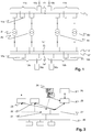
- Fig.1 shows a single line diagram of an excerpt of a substation with in-feed 10a, 10b to a double busbar 11 at the High Voltage (HV) side, a double bus bar 12 at the Medium Voltage (MV) side, and two pairs of transformers A, B coupling the bus bars.
- the HV bus bars 11 are sectionalized into in-feed related bus bar sections 11a, 11b via section circuit breakers 13, and the MV bus bars 12 are sectionalized into load bus bar sections 12a, 12b.
- the two bus bars of each section are connected via coupling circuit breakers 15, 16.
- the two transformer pairs feed the two load bus bar segments 12a, 12b and the respective loads 18a, 18b at the MV side individually, i.e.
- section circuit breaker 13, 14 are open. Adjacent to the circuit breakers 13, 14, 15, 16, a number of disconnectors (not depicted in Fig.1 ) are generally provided. Accordingly, and depending on the state of the latter and the coupling circuit breakers, other generic transformer pairs such as A1B1 or A1B2 could be formed.
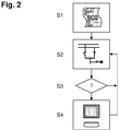
- Fig.2 is a flowchart of a process of implementing a load transfer function according to an embodiment of the invention.
- a static topology or structure of the substation in standardized description or format is provided and read.
- a second step S2 during regular operation of the SA system, messages indicative of a status of at least one switching device in the substation, generated by an IED of the SA system and transmitted over a SA communication network, are intercepted and evaluated.
- said standardized description is a Substation Configuration Description (SCD) file
- said network messages are Generic Object Oriented Substation Events (GOOSE) or MMS reporting.
- the load transfer expert program decides whether, for the current dynamic substation topology, in case of a forthcoming failure of a single primary device a load transfer would be possible and allowed.
- the latter include an indication or pre-selection of specific circuit breakers or other switching devices to be operated, and/or transformer tap changers to be adjusted.
- step S4 finally, the remedial action is stored for further reference, to be consulted in case the assumed hypothetical failure scenario actually occurs, and/or to be presented to an operator of the SA system.
- the process resumes at step S2 as soon as a change to the dynamic substation topology is reported.
- the analysis in case of transformer auto close in view of a failure or disconnection of transformer A1 includes verifying that, at the very instant; the unaffected or remaining transformers A2, B1, B2 are connected in parallel at the HV side and together have the capacity to supply the total load 18a plus 18b.
- Any alternative path between the bus bar segments 11a, 12a of the affected transformer A1 encompasses, at the MV side, at least one of the section circuit breakers 14', 14" and the coupling circuit breakers 16a, 16b.
- the first one includes section circuit breaker 14' only, while the second one involves both coupling circuit breakers 16a, 16b as well as section circuit breaker 14". As long as no disconnectors are open and section circuit breaker 14' is not blocked, the first possibility is preferred for involving fewer devices. Accordingly, upon disconnection of A1, some of the circuit breakers 14, 16 are closed, and the bus bar segments 12a and 12b at MV side are automatically connected thus joining the remaining transformer A2 to the healthy transformer pair B1, B2. The total load is then provided by the three transformers A2, B1, B2 at more or less equal shares.
- Detection and identification of an expected failure case then triggers the closing of the circuit breakers pre-selected for this failure case according to the previous steps.
- Detection of a failure situation is arranged for via monitoring of network messages on the SA communication network that are indicative of specific trigger events, such as the connection state of the transformers or, more general, instantaneous topology changes.
- Another possibility is to trigger the auto close operation by means of transformer protection trips. Relevant trips can also be found in the SCD file by looking to PTOC (Time dependent Over Current), PDIF (Differential Protection), or PTRC (Trip Conditioning matrix) Logical Nodes allocated to the transformers.
- the closing operation for the circuit breakers can be done via the normal Select-Before-Operate mechanism needing no additional engineering at the bay controllers.
- the operation of disconnectors as part of the load transfer function is to be avoided.
- the topology analysis function can signal to the bay controllers that a circuit breaker is selected for transformer auto close operation. Hence, as soon as the transformer trip occurs, the bay controller can directly close the selected circuit breaker, thus reducing the load transfer time from 1-2 seconds down to 10 -100 ms.
- Fig.3 shows an exemplary architecture for a centralized implementation of Transformer Auto Close (TRAC) functionality according to the present invention.
- a substation communication network or station bus 20 according to IEC 61850 is depicted, communicatively connecting a number of IEDs to an IEC 61850 OPC server 21 assigned to a substation level of the SA system.
- the OPC server 21 is connected to a MicroSCADA 22 and Gateway 23 application (indicated in Fig.3 by broken connectors), enabling the latter to interact with the IEDs.
- the connection to the process via the IEC 61850 OPC server 21 is configured by means of an SCD file 24. Additionally, triggering transformer protection trips are also configured by means of the SCD file of the substation.
- the TRAC functionality 25 is configured by means of the SCD file 24.
- the signals to control and monitor the TRAC function itself are provided to an HMI 26.
- TRAC controlling and monitoring may be enabled to the abovementioned OPC clients MicroSCADA 22 and Gateway 23 by means of the OPC server 21.
- TRAC is modelled as IEC 61850 IED, wherein the Implemented IED Description IID file for such a virtual IEC 61850 IED can be generated automatically from the SCD file, as described in the unpublished patent application EP09162906.3 . Due to the switch yard related naming scheme of logical devices and logical nodes in the IID file, the TRAC application connects automatically to the former.
- the interface description for controlling and monitoring the load transfer application can be generated automatically from a formal description or structure of the base SA system as e.g. comprised in an IEC 61850 SCD file.
- the interface data is structured into Logical Nodes according to IEC 61850, whereby the LNs in turn are further connected to the process single line diagram and optionally integrated into the SCD file of the base SA system, thereby generating an enhanced SCD file.
- the topology based analysis part is allocated to one IED, which then communicates to other IEDs, such as the bay controllers, about the selected circuit breakers in case of a TRAC trigger.
- the circuit breaker related logical nodes are allocated to the appropriate bay controllers.
Claims (6)
- Verfahren zur Implementierung einer Lastumschaltfunktion in einem Unterstationsautomatisierungs-,("Substation Automation", SA)-,System für eine Unterstation, die einer Last (18) elektrische Energie zuführt, aufweisend:- Auslesen einer standardisierten Konfigurationsbeschreibung des SA-Systems und Erhalten einer statischen Topologie, die wenigstens einen Teil der Unterstation repräsentiert, sowie von Informationen über Primärelemente der Unterstation daraus,- Aktualisieren einer dynamischen Unterstationstopologie basierend auf einem Schalterstatus einer Schaltvorrichtung (13, 14, 15, 16) der Unterstation,- Identifizieren für einen Transformator (A1) der eine erste Sammelschiene (11) mit einer zweiten Sammelschiene (12) der Unterstation verbindet, von Primärelementen (13, 15, B, 14, 16), die zwischen der ersten und der zweiten Sammelschiene angeordnet sind, basierend auf der dynamischen Unterstationstopologie,- Bestimmen einer Lastumschaltfunktion durch Auswählen eines Primärelements (13, 14), das aktiviert werden muss, um die erste mit der zweiten Sammelschiene zu verbinden, basierend auf einem Status der identifizierten Primärelemente (13, 15, B, 14, 16), und- Speichern der Lastumschaltfunktion, die im Falle eines Ausfalls des Transformators (A1) ausgeführt werden soll,dadurch gekennzeichnet, dass
ein Prozess, der die Schritte des Aktualisierens der dynamischen Unterstationstopologie, Bestimmens einer Lastumschaltfunktion und Speicherns der Lastumschaltfunktion aufweist, wiederholt wird, sobald eine Änderung der dynamischen Unterstationstopologie gemeldet wird. - Verfahren nach Anspruch 1, wobei das Bestimmen der Lastumschaltfunktion aufweist:- Bestätigen, dass genügend Transformatorlastkapazität zwischen der ersten Sammelschiene (11) und der zweiten Sammelschiene (12) nach einem Ausfall des Transformators (A1) verfügbar ist.
- Verfahren nach Anspruch 2, wobei der Status der identifizierten Primärelemente (13, B, 14) eine Verfügbarkeit von Schaltvorrichtungen oder Transformatorstufenschaltern aufweist.
- Verfahren nach einem der Ansprüche 1 bis 3, wobei das SA-System ein Kommunikationsnetzwerk (20) aufweist, wobei das Verfahren aufweist:- wiederholtes Aktualisieren der dynamischen Unterstationstopologie basierend auf Netzwerknachrichten, die einen Schalterstatus der Schaltvorrichtung (13, 14, 15, 16) anzeigen.
- Verfahren nach Anspruch 4, aufweisend:- Überwachen eines Status des Transformators basierend auf Netzwerknachrichten, die einen Gesundheitszustand und/oder eine bevorstehende Trennung des Transformators anzeigen.
- Verfahren nach einem der Ansprüche 1 bis 5, aufweisend:- Erzeugen einer Schnittstelle der Lastumschaltfunktion in Form von logischen Knoten nach IEC 61850,- Hosten der Schnittstelle auf einer Unterstationsautomatisierungsvorrichtung, die mit einem Kommunikationsnetzwerk (20) des SA-Systems verbunden ist.
Priority Applications (3)
| Application Number | Priority Date | Filing Date | Title |
|---|---|---|---|
| EP10167226.9A EP2400617B1 (de) | 2010-06-24 | 2010-06-24 | Umsetzung einer Lastübertragungsfunktion in einer Schaltanlagenautomatisierung |
| CN201110186583.8A CN102299560B (zh) | 2010-06-24 | 2011-06-24 | 实现变电站自动化负载转移功能 |
| US13/168,086 US9166407B2 (en) | 2010-06-24 | 2011-06-24 | Implementing substation automation load transfer function |
Applications Claiming Priority (1)
| Application Number | Priority Date | Filing Date | Title |
|---|---|---|---|
| EP10167226.9A EP2400617B1 (de) | 2010-06-24 | 2010-06-24 | Umsetzung einer Lastübertragungsfunktion in einer Schaltanlagenautomatisierung |
Publications (2)
| Publication Number | Publication Date |
|---|---|
| EP2400617A1 EP2400617A1 (de) | 2011-12-28 |
| EP2400617B1 true EP2400617B1 (de) | 2021-04-14 |
Family
ID=42712558
Family Applications (1)
| Application Number | Title | Priority Date | Filing Date |
|---|---|---|---|
| EP10167226.9A Active EP2400617B1 (de) | 2010-06-24 | 2010-06-24 | Umsetzung einer Lastübertragungsfunktion in einer Schaltanlagenautomatisierung |
Country Status (3)
| Country | Link |
|---|---|
| US (1) | US9166407B2 (de) |
| EP (1) | EP2400617B1 (de) |
| CN (1) | CN102299560B (de) |
Families Citing this family (44)
| Publication number | Priority date | Publication date | Assignee | Title |
|---|---|---|---|---|
| US8908531B2 (en) * | 2011-08-25 | 2014-12-09 | At&T Mobility Ii Llc | Communication gateway for facilitating communications with a supervisory control and data aquisition system |
| EP2618228A1 (de) * | 2012-01-17 | 2013-07-24 | ABB Technology AG | Analyse der Datenkommunikation in einer Prozesssteuerung oder in Untergeräte eines Automatisierungssystems |
| AU2013225710B2 (en) | 2012-03-01 | 2017-09-28 | Eaton Intelligent Power Limited | Managed multi-phase operation |
| EP2688251B1 (de) * | 2012-07-16 | 2018-05-23 | ABB Schweiz AG | Verfahren und Brücke-IED, Intelligent Electronic Device, das zur Weiterleitung von Nachrichten zwischen Unter-Netzwerke angepasst ist |
| CN102768705B (zh) * | 2012-07-24 | 2014-12-10 | 杭州市电力局 | 一种基于iec61968的配电网模型互操作及功能验证方法 |
| CN103001327A (zh) * | 2012-11-16 | 2013-03-27 | 西南交通大学 | 数字化牵引变电所的集中式保护测控系统 |
| WO2014188507A1 (ja) * | 2013-05-21 | 2014-11-27 | 三菱電機株式会社 | プロセスバス対応保護制御システム、マージングユニットおよび演算装置 |
| US20140371941A1 (en) * | 2013-06-18 | 2014-12-18 | The Regents Of The University Of Colorado, A Body Corporate | Software-defined energy communication networks |
| CN104810823B (zh) | 2014-01-24 | 2017-07-14 | 国际商业机器公司 | 产生变电站负荷转供控制参数的方法、设备及系统 |
| US9519301B2 (en) * | 2014-02-26 | 2016-12-13 | Schweitzer Engineering Laboratories, Inc. | Contingency-based load shedding |
| US9954372B2 (en) * | 2014-02-26 | 2018-04-24 | Schweitzer Engineering Laboratories, Inc. | Topology determination using graph theory |
| US20150294037A1 (en) * | 2014-04-11 | 2015-10-15 | General Electric Company | System and method for automated substation design and configuration |
| US9787096B2 (en) * | 2014-10-28 | 2017-10-10 | Hamad Musabeh Ahmed Saif Alteneiji | Overall dynamic reactive power control in transmission systems |
| CN105162251B (zh) * | 2015-08-28 | 2018-08-17 | 南京南瑞继保电气有限公司 | 一种适用于保护信息系统应用分析功能的保护装置建模方法 |
| ITUB20153818A1 (it) * | 2015-09-23 | 2017-03-23 | Ansaldo Energia Spa | Rete elettrica di media tensione |
| CN105375465A (zh) * | 2015-11-06 | 2016-03-02 | 国网上海市电力公司 | 城市中心区配电网及负荷转供方法 |
| CN105790264A (zh) * | 2016-04-19 | 2016-07-20 | 梅照付 | 电力电网供给方法 |
| CN105870917A (zh) * | 2016-04-19 | 2016-08-17 | 梅照付 | 一种电力电网供给系统 |
| CN107491569B (zh) * | 2016-06-13 | 2020-09-08 | 四川艾德瑞电气有限公司 | 基于iec61850标准goose、sv技术的变电站系统故障在线仿真方法 |
| US10763695B2 (en) | 2016-07-26 | 2020-09-01 | Schweitzer Engineering Laboratories, Inc. | Microgrid power flow monitoring and control |
| CN106330358B (zh) * | 2016-08-31 | 2019-02-12 | 中电华瑞技术有限公司 | 一种宽带载波仿真测试系统 |
| US10594138B2 (en) | 2016-10-04 | 2020-03-17 | Schweitzer Engineering Laboratories, Inc. | Detection and remediation of transients in electric power systems |
| US10833507B2 (en) | 2016-11-29 | 2020-11-10 | Schweitzer Engineering Laboratories, Inc. | Island detection and control of a microgrid |
| EP3367637B1 (de) * | 2017-02-23 | 2022-05-11 | Schneider Electric Industries SAS | Umspannstationsspannungsreplika basierend auf digitaler spannung |
| CN108737137A (zh) * | 2017-04-18 | 2018-11-02 | 国家计算机网络与信息安全管理中心 | 用于识别网络拓扑的方法、装置、系统和计算机可读介质 |
| CN107221928B (zh) * | 2017-05-23 | 2024-02-06 | 国网浙江省电力公司杭州供电公司 | 一种基于tsc的馈线可接入容量计算方法及位置调整方法 |
| CN108156049B (zh) * | 2017-11-22 | 2021-02-12 | 国网辽宁省电力有限公司电力科学研究院 | 一种就地化保护装置goose虚回路测试及管理系统 |
| CN108153965B (zh) * | 2017-12-22 | 2021-08-24 | 北京四方继保自动化股份有限公司 | 一种基于scd文件的间隔分图自动生成的方法 |
| CN108667019A (zh) * | 2018-06-13 | 2018-10-16 | 浙江大学 | 一种用于配电网可靠性分析的简化配电网状态模型的方法 |
| US11009931B2 (en) | 2018-07-17 | 2021-05-18 | Schweitzer Engineering Laboratories, Inc. | Voltage assessment prediction system for load/generation shedding |
| US10931109B2 (en) | 2019-01-10 | 2021-02-23 | Schweitzer Engineering Laboratories, Inc. | Contingency based load shedding system for both active and reactive power |
| US10992134B2 (en) | 2019-05-10 | 2021-04-27 | Schweitzer Engineering Laboratories, Inc. | Load shedding system for both active and reactive power based on system perturbation |
| CN111967736A (zh) * | 2020-07-30 | 2020-11-20 | 许继集团有限公司 | 一种基于大数据平台的变电站倒负荷控制方法及系统 |
| CN114256833A (zh) * | 2020-09-21 | 2022-03-29 | 周雅娟 | 一种供电系统、控制方法及存储介质 |
| US11177657B1 (en) | 2020-09-25 | 2021-11-16 | Schweitzer Engineering Laboratories, Inc. | Universal power flow dynamic simulator |
| CN112256922B (zh) * | 2020-10-09 | 2023-07-11 | 深圳供电局有限公司 | 一种故障停电快速识别方法及系统 |
| CN112528449B (zh) * | 2021-01-01 | 2022-07-05 | 青岛公能新能源科技有限公司 | 一种配电网计算母线形成方法 |
| CN112800638B (zh) * | 2021-04-12 | 2021-08-13 | 广东工业大学 | 一种智能变电站仿真测试方法、装置、终端及存储介质 |
| US11735913B2 (en) | 2021-05-25 | 2023-08-22 | Schweitzer Engineering Laboratories, Inc. | Autonomous real-time remedial action scheme (RAS) |
| CN113363968B (zh) * | 2021-05-26 | 2022-09-02 | 广东韶钢松山股份有限公司 | 一种新老变电站配电系统不停电转移负荷的方法 |
| CN113315233B (zh) * | 2021-06-17 | 2022-12-16 | 上海山源电子科技股份有限公司 | 电网拓扑图自动绘制方法及系统 |
| US11929608B2 (en) | 2021-09-01 | 2024-03-12 | Schweitzer Engineering Laboratories, Inc. | Systems and methods for operating an islanded distribution substation using inverter power generation |
| CN114069606B (zh) * | 2021-09-28 | 2023-06-06 | 国网安徽省电力有限公司滁州供电公司 | 一种模拟变电站全停时负荷转移的自动计算系统 |
| CN115207926B (zh) * | 2022-09-15 | 2023-01-24 | 广东电网有限责任公司湛江供电局 | 一种配电网中压线路可转供电能力的测算方法及相关装置 |
Citations (2)
| Publication number | Priority date | Publication date | Assignee | Title |
|---|---|---|---|---|
| EP2101393A1 (de) * | 2008-03-10 | 2009-09-16 | ABB Research Ltd | Verteilungssteuergerät und Verfahren zum Identifizieren eines Inselnetzes und zum Übermitteln einer normierten Bezeichnung des Inselnetzes zu einem anderen Verteilungssteuergerät |
| WO2010066279A1 (de) * | 2008-12-10 | 2010-06-17 | Siemens Aktiengesellschaft | Verfahren und schutzgerät zum überwachen einer sammelschiene eines elektrischen energieversorgungsnetzes |
Family Cites Families (9)
| Publication number | Priority date | Publication date | Assignee | Title |
|---|---|---|---|---|
| EP1191662B1 (de) | 2000-09-21 | 2010-06-16 | ABB Schweiz AG | Konfiguration eines Leitsystems einer elektrischen Schaltanlage |
| US7356422B2 (en) * | 2006-04-07 | 2008-04-08 | Schweitzer Engineering Laboratories, Inc. | Apparatus and method for high-speed load shedding in an electrical power system |
| EP1976218A1 (de) * | 2007-03-30 | 2008-10-01 | ABB Technology AG | Verfahren zur Konfigurierung eines intelligenten elektronischen Gerätes |
| EP2088444A1 (de) | 2008-02-11 | 2009-08-12 | ABB Research Ltd. | Systemebenentests für Automatisierungssysteme einer Unterstation |
| ES2367887T3 (es) * | 2008-08-18 | 2011-11-10 | Abb Technology Ag | Configuración de un sistema de control de proceso. |
| US8041465B2 (en) * | 2008-10-09 | 2011-10-18 | General Electric Company | Voltage control at windfarms |
| EP2194656B1 (de) * | 2008-12-03 | 2014-06-25 | ABB Research Ltd. | System zur Datenverwaltung für elektrische Energieversorgungsnetze |
| EP2264967B1 (de) | 2009-06-17 | 2017-12-13 | ABB Schweiz AG | Automatisierungsanwendung einer Zwischenrampenunterstation |
| US8918842B2 (en) * | 2010-02-19 | 2014-12-23 | Accenture Global Services Limited | Utility grid command filter system |
-
2010
- 2010-06-24 EP EP10167226.9A patent/EP2400617B1/de active Active
-
2011
- 2011-06-24 CN CN201110186583.8A patent/CN102299560B/zh active Active
- 2011-06-24 US US13/168,086 patent/US9166407B2/en active Active
Patent Citations (2)
| Publication number | Priority date | Publication date | Assignee | Title |
|---|---|---|---|---|
| EP2101393A1 (de) * | 2008-03-10 | 2009-09-16 | ABB Research Ltd | Verteilungssteuergerät und Verfahren zum Identifizieren eines Inselnetzes und zum Übermitteln einer normierten Bezeichnung des Inselnetzes zu einem anderen Verteilungssteuergerät |
| WO2010066279A1 (de) * | 2008-12-10 | 2010-06-17 | Siemens Aktiengesellschaft | Verfahren und schutzgerät zum überwachen einer sammelschiene eines elektrischen energieversorgungsnetzes |
Non-Patent Citations (2)
| Title |
|---|
| SERGIO KIMURA ET AL: "Applying IEC 61850 to Real Life: Modernization Project for 30 Electrical Substations", 21 June 2010 (2010-06-21), 1st Annual Protection, Automation and Control World Conference, pages 1 - 16, XP055503776, Retrieved from the Internet <URL:https://cdn.selinc.com/assets/Literature/Publications/Technical%20Papers/6308_Applying61850_RA_20080403_Web.pdf?v=20150812-084425> [retrieved on 20180831] * |
| SERGIO KIMURA ET AL: "Applying IEC 61850 to Real Life: Modernization Project for 30 Electrical Substations, Passage", 3 April 2008 (2008-04-03), XP002534710, Retrieved from the Internet <URL:http://www.energycentral.com/download/products/6308_Applying61850_RA_20080403.pdf> [retrieved on 20090806] * |
Also Published As
| Publication number | Publication date |
|---|---|
| CN102299560A (zh) | 2011-12-28 |
| US9166407B2 (en) | 2015-10-20 |
| US20110320058A1 (en) | 2011-12-29 |
| CN102299560B (zh) | 2015-10-21 |
| EP2400617A1 (de) | 2011-12-28 |
Similar Documents
| Publication | Publication Date | Title |
|---|---|---|
| EP2400617B1 (de) | Umsetzung einer Lastübertragungsfunktion in einer Schaltanlagenautomatisierung | |
| US9484738B2 (en) | Operating a substation automation system | |
| EP1976177B1 (de) | Unterstations-Automatisierungssystem mit erhöhter Verfügbarkeit | |
| US8433451B2 (en) | Substation automation with redundant protection | |
| US10012681B2 (en) | Testing of a substation automation system | |
| EP2522065B1 (de) | Verfahren und anordnung zur leistungsverwaltung in unterstationen | |
| US8599526B2 (en) | Protection lockout in substation automation | |
| EP2264967B1 (de) | Automatisierungsanwendung einer Zwischenrampenunterstation | |
| EP2933891B1 (de) | Lastwiederherstellung in einer Hoch- oder Mittelspannungsunterstation | |
| EP2086088B1 (de) | Bestimmen einer Busspannung | |
| Allen | Effects of wide-area control on the protection and operation of distribution networks | |
| US20230098127A1 (en) | Method for controlling an energy network, agent device, network control arrangement and system | |
| Pellini et al. | Fuzzy logic applied to registration of alarms and events in substations with IEC 61850 | |
| Dolezilek et al. | Upgrading from a successful emergency control system to a wide-area monitoring, protection, automation, and control system for the country of Georgia power system | |
| Juárez et al. | Ethernet-Based Protection and Control System for the Tabasco Substation: Design Concepts, Testing, and Field Performance |
Legal Events
| Date | Code | Title | Description |
|---|---|---|---|
| AK | Designated contracting states |
Kind code of ref document: A1 Designated state(s): AL AT BE BG CH CY CZ DE DK EE ES FI FR GB GR HR HU IE IS IT LI LT LU LV MC MK MT NL NO PL PT RO SE SI SK SM TR |
|
| AX | Request for extension of the european patent |
Extension state: BA ME RS |
|
| PUAI | Public reference made under article 153(3) epc to a published international application that has entered the european phase |
Free format text: ORIGINAL CODE: 0009012 |
|
| 17P | Request for examination filed |
Effective date: 20120622 |
|
| RAP1 | Party data changed (applicant data changed or rights of an application transferred) |
Owner name: ABB SCHWEIZ AG |
|
| STAA | Information on the status of an ep patent application or granted ep patent |
Free format text: STATUS: EXAMINATION IS IN PROGRESS |
|
| 17Q | First examination report despatched |
Effective date: 20180907 |
|
| GRAP | Despatch of communication of intention to grant a patent |
Free format text: ORIGINAL CODE: EPIDOSNIGR1 |
|
| STAA | Information on the status of an ep patent application or granted ep patent |
Free format text: STATUS: GRANT OF PATENT IS INTENDED |
|
| INTG | Intention to grant announced |
Effective date: 20201106 |
|
| RIC1 | Information provided on ipc code assigned before grant |
Ipc: H02J 3/00 20060101AFI20201027BHEP Ipc: H04B 3/54 20060101ALN20201027BHEP |
|
| GRAS | Grant fee paid |
Free format text: ORIGINAL CODE: EPIDOSNIGR3 |
|
| GRAA | (expected) grant |
Free format text: ORIGINAL CODE: 0009210 |
|
| STAA | Information on the status of an ep patent application or granted ep patent |
Free format text: STATUS: THE PATENT HAS BEEN GRANTED |
|
| RAP1 | Party data changed (applicant data changed or rights of an application transferred) |
Owner name: ABB POWER GRIDS SWITZERLAND AG |
|
| AK | Designated contracting states |
Kind code of ref document: B1 Designated state(s): AL AT BE BG CH CY CZ DE DK EE ES FI FR GB GR HR HU IE IS IT LI LT LU LV MC MK MT NL NO PL PT RO SE SI SK SM TR |
|
| REG | Reference to a national code |
Ref country code: GB Ref legal event code: FG4D |
|
| RIN1 | Information on inventor provided before grant (corrected) |
Inventor name: WIMMER, WOLFGANG Inventor name: RIETMANN, PETER |
|
| REG | Reference to a national code |
Ref country code: CH Ref legal event code: EP |
|
| REG | Reference to a national code |
Ref country code: DE Ref legal event code: R096 Ref document number: 602010066792 Country of ref document: DE |
|
| REG | Reference to a national code |
Ref country code: IE Ref legal event code: FG4D |
|
| REG | Reference to a national code |
Ref country code: AT Ref legal event code: REF Ref document number: 1383319 Country of ref document: AT Kind code of ref document: T Effective date: 20210515 |
|
| REG | Reference to a national code |
Ref country code: LT Ref legal event code: MG9D |
|
| REG | Reference to a national code |
Ref country code: AT Ref legal event code: MK05 Ref document number: 1383319 Country of ref document: AT Kind code of ref document: T Effective date: 20210414 |
|
| REG | Reference to a national code |
Ref country code: NL Ref legal event code: MP Effective date: 20210414 |
|
| PG25 | Lapsed in a contracting state [announced via postgrant information from national office to epo] |
Ref country code: LT Free format text: LAPSE BECAUSE OF FAILURE TO SUBMIT A TRANSLATION OF THE DESCRIPTION OR TO PAY THE FEE WITHIN THE PRESCRIBED TIME-LIMIT Effective date: 20210414 Ref country code: NL Free format text: LAPSE BECAUSE OF FAILURE TO SUBMIT A TRANSLATION OF THE DESCRIPTION OR TO PAY THE FEE WITHIN THE PRESCRIBED TIME-LIMIT Effective date: 20210414 Ref country code: FI Free format text: LAPSE BECAUSE OF FAILURE TO SUBMIT A TRANSLATION OF THE DESCRIPTION OR TO PAY THE FEE WITHIN THE PRESCRIBED TIME-LIMIT Effective date: 20210414 Ref country code: HR Free format text: LAPSE BECAUSE OF FAILURE TO SUBMIT A TRANSLATION OF THE DESCRIPTION OR TO PAY THE FEE WITHIN THE PRESCRIBED TIME-LIMIT Effective date: 20210414 Ref country code: AT Free format text: LAPSE BECAUSE OF FAILURE TO SUBMIT A TRANSLATION OF THE DESCRIPTION OR TO PAY THE FEE WITHIN THE PRESCRIBED TIME-LIMIT Effective date: 20210414 Ref country code: BG Free format text: LAPSE BECAUSE OF FAILURE TO SUBMIT A TRANSLATION OF THE DESCRIPTION OR TO PAY THE FEE WITHIN THE PRESCRIBED TIME-LIMIT Effective date: 20210714 |
|
| PG25 | Lapsed in a contracting state [announced via postgrant information from national office to epo] |
Ref country code: SE Free format text: LAPSE BECAUSE OF FAILURE TO SUBMIT A TRANSLATION OF THE DESCRIPTION OR TO PAY THE FEE WITHIN THE PRESCRIBED TIME-LIMIT Effective date: 20210414 Ref country code: GR Free format text: LAPSE BECAUSE OF FAILURE TO SUBMIT A TRANSLATION OF THE DESCRIPTION OR TO PAY THE FEE WITHIN THE PRESCRIBED TIME-LIMIT Effective date: 20210715 Ref country code: IS Free format text: LAPSE BECAUSE OF FAILURE TO SUBMIT A TRANSLATION OF THE DESCRIPTION OR TO PAY THE FEE WITHIN THE PRESCRIBED TIME-LIMIT Effective date: 20210814 Ref country code: LV Free format text: LAPSE BECAUSE OF FAILURE TO SUBMIT A TRANSLATION OF THE DESCRIPTION OR TO PAY THE FEE WITHIN THE PRESCRIBED TIME-LIMIT Effective date: 20210414 Ref country code: PT Free format text: LAPSE BECAUSE OF FAILURE TO SUBMIT A TRANSLATION OF THE DESCRIPTION OR TO PAY THE FEE WITHIN THE PRESCRIBED TIME-LIMIT Effective date: 20210816 Ref country code: PL Free format text: LAPSE BECAUSE OF FAILURE TO SUBMIT A TRANSLATION OF THE DESCRIPTION OR TO PAY THE FEE WITHIN THE PRESCRIBED TIME-LIMIT Effective date: 20210414 Ref country code: NO Free format text: LAPSE BECAUSE OF FAILURE TO SUBMIT A TRANSLATION OF THE DESCRIPTION OR TO PAY THE FEE WITHIN THE PRESCRIBED TIME-LIMIT Effective date: 20210714 Ref country code: ES Free format text: LAPSE BECAUSE OF FAILURE TO SUBMIT A TRANSLATION OF THE DESCRIPTION OR TO PAY THE FEE WITHIN THE PRESCRIBED TIME-LIMIT Effective date: 20210414 |
|
| REG | Reference to a national code |
Ref country code: DE Ref legal event code: R097 Ref document number: 602010066792 Country of ref document: DE |
|
| RAP4 | Party data changed (patent owner data changed or rights of a patent transferred) |
Owner name: HITACHI ENERGY SWITZERLAND AG |
|
| PG25 | Lapsed in a contracting state [announced via postgrant information from national office to epo] |
Ref country code: CZ Free format text: LAPSE BECAUSE OF FAILURE TO SUBMIT A TRANSLATION OF THE DESCRIPTION OR TO PAY THE FEE WITHIN THE PRESCRIBED TIME-LIMIT Effective date: 20210414 Ref country code: DK Free format text: LAPSE BECAUSE OF FAILURE TO SUBMIT A TRANSLATION OF THE DESCRIPTION OR TO PAY THE FEE WITHIN THE PRESCRIBED TIME-LIMIT Effective date: 20210414 Ref country code: EE Free format text: LAPSE BECAUSE OF FAILURE TO SUBMIT A TRANSLATION OF THE DESCRIPTION OR TO PAY THE FEE WITHIN THE PRESCRIBED TIME-LIMIT Effective date: 20210414 Ref country code: SM Free format text: LAPSE BECAUSE OF FAILURE TO SUBMIT A TRANSLATION OF THE DESCRIPTION OR TO PAY THE FEE WITHIN THE PRESCRIBED TIME-LIMIT Effective date: 20210414 Ref country code: SK Free format text: LAPSE BECAUSE OF FAILURE TO SUBMIT A TRANSLATION OF THE DESCRIPTION OR TO PAY THE FEE WITHIN THE PRESCRIBED TIME-LIMIT Effective date: 20210414 Ref country code: MC Free format text: LAPSE BECAUSE OF FAILURE TO SUBMIT A TRANSLATION OF THE DESCRIPTION OR TO PAY THE FEE WITHIN THE PRESCRIBED TIME-LIMIT Effective date: 20210414 Ref country code: RO Free format text: LAPSE BECAUSE OF FAILURE TO SUBMIT A TRANSLATION OF THE DESCRIPTION OR TO PAY THE FEE WITHIN THE PRESCRIBED TIME-LIMIT Effective date: 20210414 |
|
| REG | Reference to a national code |
Ref country code: CH Ref legal event code: PL |
|
| PLBE | No opposition filed within time limit |
Free format text: ORIGINAL CODE: 0009261 |
|
| STAA | Information on the status of an ep patent application or granted ep patent |
Free format text: STATUS: NO OPPOSITION FILED WITHIN TIME LIMIT |
|
| REG | Reference to a national code |
Ref country code: BE Ref legal event code: MM Effective date: 20210630 |
|
| 26N | No opposition filed |
Effective date: 20220117 |
|
| PG25 | Lapsed in a contracting state [announced via postgrant information from national office to epo] |
Ref country code: LU Free format text: LAPSE BECAUSE OF NON-PAYMENT OF DUE FEES Effective date: 20210624 |
|
| PG25 | Lapsed in a contracting state [announced via postgrant information from national office to epo] |
Ref country code: LI Free format text: LAPSE BECAUSE OF NON-PAYMENT OF DUE FEES Effective date: 20210630 Ref country code: IE Free format text: LAPSE BECAUSE OF NON-PAYMENT OF DUE FEES Effective date: 20210624 Ref country code: CH Free format text: LAPSE BECAUSE OF NON-PAYMENT OF DUE FEES Effective date: 20210630 |
|
| PG25 | Lapsed in a contracting state [announced via postgrant information from national office to epo] |
Ref country code: IS Free format text: LAPSE BECAUSE OF FAILURE TO SUBMIT A TRANSLATION OF THE DESCRIPTION OR TO PAY THE FEE WITHIN THE PRESCRIBED TIME-LIMIT Effective date: 20210814 Ref country code: AL Free format text: LAPSE BECAUSE OF FAILURE TO SUBMIT A TRANSLATION OF THE DESCRIPTION OR TO PAY THE FEE WITHIN THE PRESCRIBED TIME-LIMIT Effective date: 20210414 |
|
| REG | Reference to a national code |
Ref country code: DE Ref legal event code: R081 Ref document number: 602010066792 Country of ref document: DE Owner name: HITACHI ENERGY SWITZERLAND AG, CH Free format text: FORMER OWNER: ABB POWER GRIDS SWITZERLAND AG, BADEN, CH Ref country code: DE Ref legal event code: R081 Ref document number: 602010066792 Country of ref document: DE Owner name: HITACHI ENERGY LTD, CH Free format text: FORMER OWNER: ABB POWER GRIDS SWITZERLAND AG, BADEN, CH |
|
| PG25 | Lapsed in a contracting state [announced via postgrant information from national office to epo] |
Ref country code: IT Free format text: LAPSE BECAUSE OF FAILURE TO SUBMIT A TRANSLATION OF THE DESCRIPTION OR TO PAY THE FEE WITHIN THE PRESCRIBED TIME-LIMIT Effective date: 20210414 Ref country code: BE Free format text: LAPSE BECAUSE OF NON-PAYMENT OF DUE FEES Effective date: 20210630 |
|
| PG25 | Lapsed in a contracting state [announced via postgrant information from national office to epo] |
Ref country code: HU Free format text: LAPSE BECAUSE OF FAILURE TO SUBMIT A TRANSLATION OF THE DESCRIPTION OR TO PAY THE FEE WITHIN THE PRESCRIBED TIME-LIMIT; INVALID AB INITIO Effective date: 20100624 Ref country code: CY Free format text: LAPSE BECAUSE OF FAILURE TO SUBMIT A TRANSLATION OF THE DESCRIPTION OR TO PAY THE FEE WITHIN THE PRESCRIBED TIME-LIMIT Effective date: 20210414 |
|
| P01 | Opt-out of the competence of the unified patent court (upc) registered |
Effective date: 20230527 |
|
| PGFP | Annual fee paid to national office [announced via postgrant information from national office to epo] |
Ref country code: FR Payment date: 20230627 Year of fee payment: 14 Ref country code: DE Payment date: 20230620 Year of fee payment: 14 |
|
| PGFP | Annual fee paid to national office [announced via postgrant information from national office to epo] |
Ref country code: GB Payment date: 20230622 Year of fee payment: 14 |
|
| REG | Reference to a national code |
Ref country code: DE Ref legal event code: R082 Ref document number: 602010066792 Country of ref document: DE Representative=s name: DENNEMEYER & ASSOCIATES S.A., DE Ref country code: DE Ref legal event code: R081 Ref document number: 602010066792 Country of ref document: DE Owner name: HITACHI ENERGY LTD, CH Free format text: FORMER OWNER: HITACHI ENERGY SWITZERLAND AG, BADEN, CH |