EP2400608A2 - Modular warning device for networking and signalling with control and warning devices - Google Patents
Modular warning device for networking and signalling with control and warning devices Download PDFInfo
- Publication number
- EP2400608A2 EP2400608A2 EP11170224A EP11170224A EP2400608A2 EP 2400608 A2 EP2400608 A2 EP 2400608A2 EP 11170224 A EP11170224 A EP 11170224A EP 11170224 A EP11170224 A EP 11170224A EP 2400608 A2 EP2400608 A2 EP 2400608A2
- Authority
- EP
- European Patent Office
- Prior art keywords
- module
- bus
- signaling device
- signaling
- message
- Prior art date
- Legal status (The legal status is an assumption and is not a legal conclusion. Google has not performed a legal analysis and makes no representation as to the accuracy of the status listed.)
- Granted
Links
Images


Classifications
-
- H—ELECTRICITY
- H02—GENERATION; CONVERSION OR DISTRIBUTION OF ELECTRIC POWER
- H02B—BOARDS, SUBSTATIONS OR SWITCHING ARRANGEMENTS FOR THE SUPPLY OR DISTRIBUTION OF ELECTRIC POWER
- H02B1/00—Frameworks, boards, panels, desks, casings; Details of substations or switching arrangements
-
- H—ELECTRICITY
- H02—GENERATION; CONVERSION OR DISTRIBUTION OF ELECTRIC POWER
- H02B—BOARDS, SUBSTATIONS OR SWITCHING ARRANGEMENTS FOR THE SUPPLY OR DISTRIBUTION OF ELECTRIC POWER
- H02B1/00—Frameworks, boards, panels, desks, casings; Details of substations or switching arrangements
- H02B1/015—Boards, panels, desks; Parts thereof or accessories therefor
- H02B1/04—Mounting thereon of switches or of other devices in general, the switch or device having, or being without, casing
-
- H—ELECTRICITY
- H05—ELECTRIC TECHNIQUES NOT OTHERWISE PROVIDED FOR
- H05B—ELECTRIC HEATING; ELECTRIC LIGHT SOURCES NOT OTHERWISE PROVIDED FOR; CIRCUIT ARRANGEMENTS FOR ELECTRIC LIGHT SOURCES, IN GENERAL
- H05B45/00—Circuit arrangements for operating light-emitting diodes [LED]
- H05B45/10—Controlling the intensity of the light
- H05B45/12—Controlling the intensity of the light using optical feedback
-
- H—ELECTRICITY
- H05—ELECTRIC TECHNIQUES NOT OTHERWISE PROVIDED FOR
- H05B—ELECTRIC HEATING; ELECTRIC LIGHT SOURCES NOT OTHERWISE PROVIDED FOR; CIRCUIT ARRANGEMENTS FOR ELECTRIC LIGHT SOURCES, IN GENERAL
- H05B47/00—Circuit arrangements for operating light sources in general, i.e. where the type of light source is not relevant
- H05B47/10—Controlling the light source
- H05B47/105—Controlling the light source in response to determined parameters
- H05B47/11—Controlling the light source in response to determined parameters by determining the brightness or colour temperature of ambient light
-
- H—ELECTRICITY
- H01—ELECTRIC ELEMENTS
- H01H—ELECTRIC SWITCHES; RELAYS; SELECTORS; EMERGENCY PROTECTIVE DEVICES
- H01H13/00—Switches having rectilinearly-movable operating part or parts adapted for pushing or pulling in one direction only, e.g. push-button switch
- H01H13/02—Details
- H01H13/023—Light-emitting indicators
-
- H—ELECTRICITY
- H01—ELECTRIC ELEMENTS
- H01H—ELECTRIC SWITCHES; RELAYS; SELECTORS; EMERGENCY PROTECTIVE DEVICES
- H01H13/00—Switches having rectilinearly-movable operating part or parts adapted for pushing or pulling in one direction only, e.g. push-button switch
- H01H13/50—Switches having rectilinearly-movable operating part or parts adapted for pushing or pulling in one direction only, e.g. push-button switch having a single operating member
- H01H13/503—Stacked switches
-
- H—ELECTRICITY
- H01—ELECTRIC ELEMENTS
- H01H—ELECTRIC SWITCHES; RELAYS; SELECTORS; EMERGENCY PROTECTIVE DEVICES
- H01H9/00—Details of switching devices, not covered by groups H01H1/00 - H01H7/00
- H01H9/16—Indicators for switching condition, e.g. "on" or "off"
- H01H9/167—Circuits for remote indication
-
- H—ELECTRICITY
- H04—ELECTRIC COMMUNICATION TECHNIQUE
- H04L—TRANSMISSION OF DIGITAL INFORMATION, e.g. TELEGRAPHIC COMMUNICATION
- H04L12/00—Data switching networks
- H04L12/28—Data switching networks characterised by path configuration, e.g. LAN [Local Area Networks] or WAN [Wide Area Networks]
- H04L12/40—Bus networks
-
- Y—GENERAL TAGGING OF NEW TECHNOLOGICAL DEVELOPMENTS; GENERAL TAGGING OF CROSS-SECTIONAL TECHNOLOGIES SPANNING OVER SEVERAL SECTIONS OF THE IPC; TECHNICAL SUBJECTS COVERED BY FORMER USPC CROSS-REFERENCE ART COLLECTIONS [XRACs] AND DIGESTS
- Y02—TECHNOLOGIES OR APPLICATIONS FOR MITIGATION OR ADAPTATION AGAINST CLIMATE CHANGE
- Y02B—CLIMATE CHANGE MITIGATION TECHNOLOGIES RELATED TO BUILDINGS, e.g. HOUSING, HOUSE APPLIANCES OR RELATED END-USER APPLICATIONS
- Y02B20/00—Energy efficient lighting technologies, e.g. halogen lamps or gas discharge lamps
- Y02B20/40—Control techniques providing energy savings, e.g. smart controller or presence detection
Definitions
- the invention relates to a modular signaling device for networking and signaling with commonly switched to a bus and supply line command or signaling devices.
- a system for wiring and networking of electromechanical devices, in particular of signaling devices ( DE 29508773 U1 ).
- the system comprises at least one device or a function module for insertion on a control panel or in a control cabinet and an adapter for attachment to a bus line, the device or the function block on its back plug connections and on its front functional elements (for operation and / or display) having.
- Such an electromechanical device may further comprise latching elements (latching hooks) for front or rear latching.
- signaling devices for connection to a bus line are known, on which a so-called display head can be plugged.
- a light element can be accommodated in the display head ( DE 29606721 U1 ).
- the invention is based on a modular signaling device for networking and signaling with commonly switched to a bus and supply line command and signaling devices.
- This state of the art can be found in: "Product information - Smartwire-Darwin” - W0211-7601en ip / DFS 08/09 (2009) as download at www.moeller.net.
- a solution is represented by integration of special functions in a signaling device.
- the essence of the invention is the static and temporal variability and controllability of the light output of the luminous means.
- the invention is implemented in a modular signaling device for networking and signaling with commonly switched to a bus and supply line command and signaling devices.
- Signaling devices are primarily used to display a message via a visual display.
- the power parameters which are determined in particular by controlling the power supply of the optical display means are in detail: continuous light of different brightness and / or time course or change in light output, in particular consisting of certain periodic or non-periodic flashing sequences (also different brightness).
- the brightness of the luminous means is now controllable according to the invention.
- the bus can be an ASI bus.
- the central bus control is designed so that from there the necessary control data for display means - mainly light-emitting diodes (LED or OLED) - generated, transmitted, controlled and switched. This is possible both for a switched-on signaling device alone, as well as for several connected signaling devices, which are preferably also selected, groups are controlled.
- the user can influence this control data with a user program for programming the central bus control and the electronic circuit (CHIP) in the signaling device.
- the software and hardware used eg non-volatile memory, LED driver
- the performance parameters therefore consist primarily of multiple brightness levels or light outputs between 0 (OFF) and 100% (ON), and different flashing sequences. Each is selectable (principally via a 1-byte command of the central bus controller), so that when the display means is turned ON, a power parameter existing before the ON-switching state is again driven, or ON in the ON-state activated power parameter is changed or an existing before the ON-state switching power parameter is not activated again.
- One of the flashing sequences can be an irregular flickering light.
- Flicker light is particularly useful for attracting the attention of operators, so that unperiodic flashing sequences are preferably used to indicate irregularities in the operation or of hazardous conditions.
- At least one performance parameter can be set via a measurement signal of a brightness sensor connected to the bus and supply line.
- a brightness sensor has the advantage that, when the ambient brightness changes, the light output of signaling modules connected to the bus and supply lines is also modified in whole or in groups, for example dimmed. Preferably, this process can be done automatically.
- the electronic circuit (chip) of the message module is programmed, for example, so that the circuit clocks the power supply to the light emitting element (pulse-code-modulated). Regular clocking leads to a reduction of the light output (dimming), whereby the clock frequency determines the degree of reduction of the light output.
- the intermittent control with be periodic or non-periodic flashing sequences, so that the light-emitting element generates corresponding flickering light at a certain basic brightness.
- the upstream front module can be formed lockable with the message module or it can be designed as a cover of a front opening of the reporting device receiving signaling device housing.
- fastening means for detachably inserting the front module into an opening of a control panel or a control cabinet can be present on the front module.
- the message module may additionally be provided with an actuating tappet, which can be acted upon by actuating means present in the front module.
- In the message module can continue to be contacts for contacting a on a side surface of the message module (surface is perpendicular to the display page) can be formed on the message block snapped contact module.
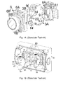
- the Fig. 1A and 1B show two modular reporting devices of the Applicant (as prior art) for networking and signaling with commonly switched to a bus and supply line command and signaling devices.
- the modules shown are a message module 3A, a front module 6, a bus coupling module 8A and 8B, a message or contact block 3B plugged laterally to the message block.
- the signaling module 3A has an optical display means (LED 20), in particular for indicating an operating state (ON and OFF) of an electrical operating means, for example an electric motor or a motor control. Furthermore, an actuating tappet 3.4 is present at the message module that can be actuated by actuating elements 6B "formed in the front module.
- LED 20 optical display means
- an actuating tappet 3.4 is present at the message module that can be actuated by actuating elements 6B "formed in the front module.
- the front module 6 is formed latched with the display side 5.1 (front) of the message module 3A.
- an adapter frame 6A is located on the front module 6.
- other blocks can be locked.
- the in Fig. 1A also shown command block 3B snaps into the adapter frame 6A.
- a command block 3B is characterized in that it also has an actuating tappet.
- the modular system is extended by a further contact system, namely by the contact in the command block 3B.
- a second position of the push button 6B "can be queried and the contact actuation to the electronics module 24 (see Fig. 2 or 3 ) are transmitted in the message block 3A.
- a display head 6B is present on the front module. This protrudes over a shaft 6C to the operator side of the message module forward.
- a ring 6B ' is placed on the shaft.
- Said shaft 6C is passed through an opening of a front panel of a panel or a device or the like and secured with the ring 6B '.
- the inner cylindrical part of the shaft 6C can be actuated as a transparent pushbutton 6B "in the direction of the signaling module, whereby the actuating tappet 3.4 present on the signaling module can be acted on.
- the modular ensemble has the function of a switch with a light indicator which is illuminated by the light source 20 (FIG. LED or OLED) comes about.
- plug contacts 9 for contacting with the socket 8 'of the bus coupling module 8A, via which the signaling module 3A is coupled to the bus and supply line 8.1.
- the bus coupling module 8A cutting contacts 8 "are present, which engage in the bus ribbon 8.1, whereby a power supply (for example, 16 V or 24 V) is tapped and message signals from the message module 3A to the central bus control (and back) are transmitted.
- a power supply for example, 16 V or 24 V
- the signaling device thus has primarily a visual display function on front panels of devices or control boxes and is releasably secured there.
- the command device with illuminated button / switch button functions as a signaling device with a control lamp, with differently colored caps (6B ") being assigned to different electrical equipment (eg electric motors) With the button / switch button illuminated by the LED from the inside Operator on or two switching states signaled
- a command function is implemented if an actuating tappet is present on the signaling module.
- the transmission of a second contact position with the command block 3B is possible. The evaluation of the contact positions and transmission of the message via the electronic module 24 to the bus system and to a central bus control.
- the Fig. 1B shows a second known device.
- One or more message blocks 3A or contact blocks 3B can be connected via a bus coupling module 8B on a base plate of a signaling device housing 16 to the bus and supply line 8.2.
- the signaling modules 3A or contact module 3B shown in the direction of the bus coupling module 8.2 are provided on the side of the respective housing with snap-in hooks 14. These snap-in hooks 14 "are hinged to the housing via film hinges and are pivotable via respective actuating levers 14"'.
- the bus and supply line is designed in this embodiment as a printed circuit board 8.2 and extends between the two cable clamp strips 10 (from left to right in the figure) on the housing bottom of the signaling device housing 16.
- the terminal strips 10 have (here in the example) eight cable terminals Anklemmung an eight-wire bus and supply line, which is not shown itself.
- This bus and supply line can be designed as a round cable and passed through the lateral round openings in the signaling device housing.
- plug-in connectors 8 '"(of which two are visible) for plugging in with the rear contacts 9 of the signaling module 3A or command module 3 B. It can also be seen that a contact module 3B' is latched parallel to the signaling module 3A and the contact module 3B ,
- the signaling device housing 16 has to the front side a housing opening 17 which is closed by a cover, are arranged in the display heads and / or actuator heads.
- Display heads and / or actuator heads are each assigned to the individual present in the signaling device housing 16 reporting or contact blocks.
- the cover with display heads and actuator heads is not shown in the drawing. However, the cover is to be interpreted as a front module in the sense of the present application.
- the message or command blocks are each housed in a flat prismatic housing 3.1 made of insulating material.
- Each housing consists of two identical half shells 3.2.
- the geometric design of the pages is approximately square or rectangular in shape.
- the display side (from) 5.1 and the display side opposite back side 5.2 are relatively narrow.
- FIGS. 2, 3 and 4 show details depending only one housing half 3.2 of the message block 3A.
- Fig. 2 there is a representation of the interior of a message module.
- the bus terminal contacts 9 see Fig. 3 .
- As a fastening means between reporting module 3A and front module 6 projecting locking hooks 14 'in the direction of the front module on the insulating housing 3.2 are available.
- FIG. 2 In the FIG. 2 is an LED 22 visible, which is in series with the bulb 20. This is a simple measure (by several others possible) to reduce the voltage on the bulb 20 (and thus the light intensity).
- FIGS. 2 and 3 Wiring and traces of the electrical and optical elements are omitted.
- the light-emitting means 20 the bus connection contacts 9 (for contacting the bus coupling module 8) on the rear side, the electronic circuit (as CHIP 24) on the housing inner wall and on the side surface of the contact module contacts 3.5 for making contact with a latchable device are shown in particular Parallel block (compare contact block 3B in Figure 1A or 3B 'in Fig. 1B ).
- the Fig. 2 further shows two side contacts 3.6 as terminal contacts for electrical connections with which laterally connectable contact blocks can be supplied.
- An optical display means (LED or OLED) 26 for displaying the bus status is present on the rear side of the message module.
- the Fig. 4 brings a representation of a half shell of a message module from the outside (5.3). Visible are a latching hook 14 ', a lighting means 20, an optical display means 26 for displaying the bus status on the back of the message module and (hidden) plug contacts 9 for contacting with the socket 8' of the bus coupling module eighth
Landscapes
- Engineering & Computer Science (AREA)
- Power Engineering (AREA)
- Details Of Connecting Devices For Male And Female Coupling (AREA)
- Small-Scale Networks (AREA)
Abstract
Description
Die Erfindung betrifft ein modular aufgebautes Meldegerät zur Vernetzung und Signalisierung mit gemeinsam an eine Bus- und Versorgungsleitung aufgeschalteten Befehls- oder Meldegeräten.The invention relates to a modular signaling device for networking and signaling with commonly switched to a bus and supply line command or signaling devices.
Bekannt ist ein System zur Verdrahtung und Vernetzung von elektromechanischen Geräten, insbesondere von Meldegeräten (
Weiterhin sind Meldegeräte zum Anschluss an eine Busleitung bekannt, auf die ein sogenannter Anzeigekopf aufgesteckt werden kann. Im Anzeigekopf kann ein Leuchtelement untergebracht sein (
Die Erfindung geht aus von einem modular aufgebauten Meldegerät zur Vernetzung und Signalisierung mit gemeinsam an eine Bus- und Versorgungsleitung aufgeschalteten Befehls- und Meldegeräten. Dieser Stand der Technik findet sich in: "Produktinformation - Smartwire-Darwin" - W0211-7601de ip/DFS 08/09 (2009) als download unter www.moeller.net.The invention is based on a modular signaling device for networking and signaling with commonly switched to a bus and supply line command and signaling devices. This state of the art can be found in: "Product information - Smartwire-Darwin" - W0211-7601en ip / DFS 08/09 (2009) as download at www.moeller.net.
Es ist bisher nicht üblich, Meldegeräte in ihrer Helligkeit einstellbar zu machen. Bisher sind Meldegeräte mit Leuchtmitteln ausgestattet, die eine maximale Helligkeit liefern, um Meldungen bei schwachem Licht oder bei Kunstlicht gut erkennbar zu machen. Als ,Nachfolger' kleiner Glühlampen mit beschränkter Leistung, deren Verlustleistung in den Bauraum noch abgeführt werden konnte, werden heute LEDs, bzw. Leistungs-LEDs mit erhöhter Lichtleistung eingesetzt. Gerade bei Anwendungen in geringer Umgebungshelligkeit kann dies zum Problem der Überstrahlung führen.It has not been customary to make signaling devices adjustable in their brightness. Up to now, signaling devices have been equipped with bulbs that provide maximum brightness in order to make messages easily recognizable in low light or under artificial light. As 'successors' of small incandescent lamps with limited power, their power dissipation in the space could still be dissipated, today LEDs, or power LEDs are used with increased light output. Especially in applications in low ambient brightness, this can lead to the problem of overshoot.
Es entsteht jedoch der Wunsch, dass die Lichtleistung veränderlich geschaltet werden kann. Allerdings ist der technische Aufwand relativ groß, um konventionelle Befehls- und Meldegeräte umzurüsten. Üblicherweise hängen Meldegeräte und Leuchtmittel an derselben Versorgungsspannung. Eine Trennung der Versorgungsspannung für Meldegeräte und Leuchtmittel wäre nötig. Damit entstehen erhöhter Material- und Arbeitsaufwand und höhere Kosten. Weiter nicht zu vergessen, dass durch verschiedene (oder zusätzliche) Netzteile erhöhte Verluste auftreten. Insgesamt vermindert sich dann die Energieeffizienz der Geräte. Es können auch elektronische Funktionsprobleme entstehen, wenn eine zentrale Steuerung Signale unterschiedlicher Spannungen zu verarbeiten hat.However, there is a desire that the light output can be changed variable. However, the technical complexity is relatively large to convert conventional command and signaling devices. Typically, signaling devices and bulbs depend on the same supply voltage. A separation of the supply voltage for signaling devices and bulbs would be necessary. This results in increased material and labor costs and higher costs. Not to forget that different (or additional) power supplies cause increased losses. Overall, then reduces the energy efficiency of the devices. Electronic functional problems can also arise if a central control has to process signals of different voltages.
Es ist daher die Aufgabe der Erfindung, Stromversorgung und Spannung von Leuchtmitteln an Meldegeräten veränderbar zu gestalten.It is therefore an object of the invention to make power supply and voltage of lighting on signaling devices changeable.
Die Lösung der Aufgabe findet sich in den Merkmalen des Hauptanspruchs. Weiterführende und vorteilhafte Ausgestaltungen sind in Unteransprüchen formuliert.The solution of the problem can be found in the features of the main claim. Further and advantageous embodiments are formulated in subclaims.
Mit der Erfindung wird durch Integration von speziellen Funktionen in einem Meldegerät eine Lösung dargestellt. Der Kern der Erfindung besteht in der statischen und zeitlichen Veränder- und Steuerbarkeit der Lichtleistung des Leuchtmittels.With the invention, a solution is represented by integration of special functions in a signaling device. The essence of the invention is the static and temporal variability and controllability of the light output of the luminous means.
Die Erfindung wird in einem modular aufgebauten Meldegerät zur Vernetzung und Signalisierung mit gemeinsam an eine Bus- und Versorgungsleitung aufgeschalteten Befehls- und Meldegeräten umgesetzt. Meldegeräte dienen vornehmlich der Darstellung einer Meldung über eine optische Anzeige.The invention is implemented in a modular signaling device for networking and signaling with commonly switched to a bus and supply line command and signaling devices. Signaling devices are primarily used to display a message via a visual display.
Typische Spannungen an Versorgungsleitungen liegen typisch etwa bei 16 oder 24 V. Das Meldegerät umfasst folgende Module:
- einen Meldebaustein mit einem optischen Anzeigemittel, insbesondere zur Anzeige eines Betriebszustands (EIN oder AUS) eines elektrischen Betriebsmittels, beispielsweise eines Elektromotors oder einer Motorsteuerung, und mit in seinem Gehäuse gelagerten Elektronik-Baustein zur Buskommunikation,
- ein auf einer Anzeigeseite des Meldebausteins dem Meldebaustein vorgelagertes Frontmodul mit einem Anzeigekopf und
- ein Bus-Kupplungsmodul zur Kupplung des Meldebausteins auf einer der Anzeigeseite gegenüberliegenden Rückseite des Meldebausteins mit der Bus- und Versorgungsleitung,
- a message module with an optical display means, in particular for displaying an operating state (ON or OFF) of an electrical equipment, such as an electric motor or a motor controller, and with mounted in its housing electronics module for bus communication,
- an upstream on a display page of the message block the message block front module with a display head and
- a bus coupling module for coupling the message module on a rear side of the message module opposite the display side to the bus and supply line,
Die Leistungsparameter, die insbesondere durch Ansteuerung der Spannungsversorgung des optischen Anzeigemittels bestimmt werden, sind im Einzelnen: Dauerlicht unterschiedlicher Helligkeit und/oder zeitlicher Verlauf oder Änderung der Lichtleistung, insbesondere bestehend aus bestimmten periodischen oder unperiodischen Blinkfolgen (ebenfalls unterschiedlicher Helligkeit).The power parameters, which are determined in particular by controlling the power supply of the optical display means are in detail: continuous light of different brightness and / or time course or change in light output, in particular consisting of certain periodic or non-periodic flashing sequences (also different brightness).
In Gegensatz zu bekannten Meldegeräten ist nach der Erfindung die Helligkeit des Leuchtmittels nunmehr steuerbar.In contrast to known signaling devices, the brightness of the luminous means is now controllable according to the invention.
Unter Verwendung einer Bus-Slave-Schaltung sind mehrere Befehls- und Meldegeräte an die Bus- und Versorgungsleitung anschließbar. Der Bus kann ein ASI-Bus sein. Die zentrale Bus-Steuerung wird so ausgestaltet, dass von dort die notwendigen Steuerdaten für Anzeigemittel - vornehmlich Leuchtdioden (LED oder OLED) - generiert, übermittelt, angesteuert und umgeschaltet werden. Dies ist sowohl möglich für ein angeschaltetes Meldegerät allein, als auch für mehrere angeschaltete Meldegeräte, die vorzugsweise auch ausgewählt, gruppenweise ansteuerbar sind. Der Anwender kann mit einem Anwenderprogramm zur Programmierung der zentralen Bus-Steuerung und der Elektronik-Schaltung (CHIP) im Meldegerät auf diese Steuerdaten Einfluss nehmen. Die eingesetzte Soft- und Hardware (z.B. nicht-flüchtiger Speicher, LED-Treiber) wird entsprechend gestaltet.Using a bus-slave circuit several command and signaling devices can be connected to the bus and supply line. The bus can be an ASI bus. The central bus control is designed so that from there the necessary control data for display means - mainly light-emitting diodes (LED or OLED) - generated, transmitted, controlled and switched. This is possible both for a switched-on signaling device alone, as well as for several connected signaling devices, which are preferably also selected, groups are controlled. The user can influence this control data with a user program for programming the central bus control and the electronic circuit (CHIP) in the signaling device. The software and hardware used (eg non-volatile memory, LED driver) will be designed accordingly.
Die Erfindung ist in mehreren, vorteilhaften Ausgestaltungen beschrieben, deren Merkmale einzeln oder in Kombination miteinander beansprucht sein können.The invention is described in several advantageous embodiments, the features of which can be claimed individually or in combination with each other.
Die Leistungsparameter (oder Aktivitätszustände) bestehen daher vorrangig aus mehreren Helligkeitsstufen oder Lichtleistungen zwischen 0 (AUS) und 100 % (EIN), und unterschiedlichen Blinkfolgen. Jede ist (vornehmlich über einen 1-byte-Befehl der zentralen Bus-Steuerung) jeweils auswählbar, so dass bei EIN-Schaltung des Anzeigemittels ein vor dem EIN-Schalt-Zustand vorhandener Leistungsparameter wiederum angesteuert wird, oder ein im EIN-Schalt-Zustand aktivierter Leistungsparameter geändert wird oder ein vor dem EIN-Schalt-Zustand vorhandener Leistungsparameter nicht wiederum aktiviert wird.The performance parameters (or activity states) therefore consist primarily of multiple brightness levels or light outputs between 0 (OFF) and 100% (ON), and different flashing sequences. Each is selectable (principally via a 1-byte command of the central bus controller), so that when the display means is turned ON, a power parameter existing before the ON-switching state is again driven, or ON in the ON-state activated power parameter is changed or an existing before the ON-state switching power parameter is not activated again.
Eine der Blinkfolgen kann ein unregelmäßiges Flackerlicht sein. Flackerlicht dient besonders zur Anregung der Aufmerksamkeit von Bedienpersonen, so dass unperiodische Blinkfolgen vorzugsweise zur Anzeige von Unregelmäßigkeiten im Betriebsablauf oder von Gefahrenzuständen eingesetzt werden sollen.One of the flashing sequences can be an irregular flickering light. Flicker light is particularly useful for attracting the attention of operators, so that unperiodic flashing sequences are preferably used to indicate irregularities in the operation or of hazardous conditions.
Mindestens ein Leistungsparameter kann über ein Mess-Signal eines an der Bus- und Versorgungsleitung aufgeschalteten Helligkeitssensors einstellbar sein. Der Einsatz eines Helligkeitssensors hat den Vorteil, dass bei Änderung der Umgebungshelligkeit die Lichtleistung von an der Bus- und Versorgungsleitung angeschalteter Meldebausteine insgesamt oder in Gruppen ebenfalls abgeändert, beispielsweise gedimmt werden. Vorzugsweise kann dieser Vorgang automatisch erfolgen.At least one performance parameter can be set via a measurement signal of a brightness sensor connected to the bus and supply line. The use of a brightness sensor has the advantage that, when the ambient brightness changes, the light output of signaling modules connected to the bus and supply lines is also modified in whole or in groups, for example dimmed. Preferably, this process can be done automatically.
Die elektronische Schaltung (Chip) des Meldebausteins ist beispielsweise so programmiert, dass die Schaltung die Spannungsversorgung zum Leuchtelement taktet (puls-code-moduliert). Regelmäßiges Takten führt zu einer Verringerung der Lichtleistung (Dimmung), wobei die Taktfrequenz den Grad der Herabsetzung der Lichtleistung bestimmt. Kombiniert oder überlagert kann die taktweise Ansteuerung mit periodischen oder unperiodischen Blinkfolgen sein, so dass das Leuchtelement bei einer bestimmten Grundhelligkeit entsprechendes Flackerlicht erzeugt.The electronic circuit (chip) of the message module is programmed, for example, so that the circuit clocks the power supply to the light emitting element (pulse-code-modulated). Regular clocking leads to a reduction of the light output (dimming), whereby the clock frequency determines the degree of reduction of the light output. Combined or superimposed, the intermittent control with be periodic or non-periodic flashing sequences, so that the light-emitting element generates corresponding flickering light at a certain basic brightness.
Das vorgelagerte Frontmodul kann mit dem Meldebaustein verrastbar ausgebildet sein oder es kann als Abdeckung einer vorderseitigen Öffnung eines das Meldegerät aufnehmenden Meldegerät-Gehäuses ausgebildet sein. Am Frontmodul können somit Befestigungsmittel zum lösbaren Einsetzen des Frontmoduls in eine Öffnung einer Schalttafel oder eines Schaltschranks vorhanden sein.The upstream front module can be formed lockable with the message module or it can be designed as a cover of a front opening of the reporting device receiving signaling device housing. Thus, fastening means for detachably inserting the front module into an opening of a control panel or a control cabinet can be present on the front module.
Der Meldebaustein kann zusätzlich mit einem Betätigungsstößel versehen sein, der von in dem Frontmodul vorhandenen Betätigungsmitteln beaufschlagbar ist.The message module may additionally be provided with an actuating tappet, which can be acted upon by actuating means present in the front module.
Es sind elektrische Kontaktmittel auf einer der Anzeigenseite gegenüber liegenden Rückseite des Meldebausteins zum Kuppeln mit dem Bus-Kupplungsmodul vorhanden, wobei mit Steck- oder Schneidkontakten die Bus- und Versorgungsleitung kontaktiert wird. Ebenfalls auf der Rückseite des Meldebausteins kann ein optisches Anzeigemittel (LED oder OLED) zur Anzeige des Bus-Status vorhanden sein.There are electrical contact means on one of the display side opposite back of the message block for coupling with the bus coupling module available, with plug or cutting contacts the bus and supply line is contacted. Also on the back of the message module may be an optical display means (LED or OLED) for displaying the bus status.
Im Meldebaustein können weiterhin Kontakte zum Kontaktieren eines auf einer Seitenfläche des Meldebausteins (Fläche liegt senkrecht zur Anzeigeseite) an den Meldebaustein aufrastbaren Kontaktbaustein ausgebildet sein.In the message module can continue to be contacts for contacting a on a side surface of the message module (surface is perpendicular to the display page) can be formed on the message block snapped contact module.
Die Erfindung wird in mehreren Figuren dargestellt, die jeweils im Einzelnen zeigen:
-
Fig. 1A und 1B : zwei modular aufgebaute Meldegeräte als Stand der Technik; -
Fig. 2 : Darstellung eines Meldebausteins (innen); -
Fig. 3 : Darstellung eines Meldebausteins mit Busanschluss-Kontakten und -
Fig. 4 : Darstellung einer Halbschale eines Meldebausteins von außen.
-
Fig. 1A and 1B : two modular signaling devices as prior art; -
Fig. 2 : Representation of a message module (inside); -
Fig. 3 : Representation of a message block with bus connection contacts and -
Fig. 4 : Representation of a half shell of a message module from the outside.
Die
Die in
Der Meldebaustein 3A weist ein optisches Anzeigemittel (LED 20) auf, insbesondere zur Anzeige eines Betriebszustands (EIN und AUS) eines elektrischen Betriebsmittels, beispielsweise eines Elektromotors oder einer Motorsteuerung. Weiterhin ist am Meldebaustein ein Betätigungsstößel 3.4 vorhanden, der von im Frontmodul ausgebildeten Betätigungsmitteln 6B" betätigt werden kann.The
Das Frontmodul 6 ist mit der Anzeigeseite 5.1 (Vorderseite) des Meldebausteins 3A verrastbar ausgebildet. Dazu befindet sich am Frontmodul 6 ein Adapterrahmen 6A. Zur Verrastung mit dem Meldebaustein sind am Meldebaustein 3A Rastnasen 14' vorhanden. Im Adapterrahmen 6A können weitere Bausteine verrastet werden. Der in
Durch eine Anordnung mehrerer Bausteine nebeneinander in einem Frontmodul wird das modulare System um ein weiteres Kontaktsystem erweitert, nämlich durch den Kontakt im Befehlsbaustein 3B. Mit dem zusätzlichen Kontakt kann eine zweite Stellung des Druckknopfs 6B" abgefragt werden und die Kontaktbetätigung an den Elektronik-Baustein 24 (siehe
Am Frontmodul ist weiterhin ein Anzeigekopf 6B vorhanden. Dieser ragt über einen Schaft 6C zur Bedienerseite des Meldebausteins nach vorn. Auf den Schaft ist ein Ring 6B' aufgesetzt. Der genannte Schaft 6C wird durch eine Öffnung einer Frontplatte einer Schalttafel oder eines Geräts oder dergleichen geführt und mit dem Ring 6B' gesichert. Das innere zylindrische Teil des Schafts 6C ist als transparenter Druckknopf 6B" in Richtung auf den Meldebaustein betätigbar; wodurch der am Meldebaustein vorhandener Betätigungsstößel 3.4 beaufschlagbar ist. Mit diesem Aufbau hat das modulare Ensemble die Funktion eines Schalters mit Leuchtanzeige, die durch das Leuchtmittel 20 (LED oder OLED) zustande kommt.On the front module continue a
Auf der Rückseite 5.2 des Meldebausteins 3A, welche der Anzeigeseite 5.1 des Meldebausteins gegenüberliegt, befinden sich Steckkontakte 9 (siehe
Das Meldegerät hat somit vornehmlich eine optische Anzeigefunktion auf Frontplatten von Geräten oder Schaltkästen und ist dort lösbar befestigt. Das Befehlsgerät mit beleuchtbarem Taster/Schalter-Knopf funktioniert als Meldegerät mit Kontroll-Lampe, wobei unterschiedlich farbige Kappen (6B") verschiedenen elektrischen Betriebsmitteln (z.B. Elektromotoren) zugeordnet sind. Mit dem von der LED von innen beleuchteten Taster/Schalter-Knopf werden einem Bediener ein- oder zwei Schaltzustände signalisiert. Neben der Anzeigefunktion ist eine Befehlsfunktion realisiert, wenn am Meldebaustein ein Betätigungsstößel vorhanden ist. Durch Betätigung über den Druckknopf 6B" wird mindestens eine Kontaktstellung weitergeben. Wie erwähnt, ist die Übermittlung einer zweiten Kontaktstellung mit dem Befehlsbaustein 3B möglich. Die Auswertung der Kontaktstellungen und Weitergabe der Meldung erfolgt über den Elektronik-Baustein 24 zum Bussystem und an eine zentrale Bus-Steuerung.The signaling device thus has primarily a visual display function on front panels of devices or control boxes and is releasably secured there. The command device with illuminated button / switch button functions as a signaling device with a control lamp, with differently colored caps (6B ") being assigned to different electrical equipment (eg electric motors) With the button / switch button illuminated by the LED from the inside Operator on or two switching states signaled In addition to the display function, a command function is implemented if an actuating tappet is present on the signaling module. As mentioned, the transmission of a second contact position with the
Die
Die Bus- und Versorgungsleitung ist in dieser Ausführungsform als Leiterplatte 8.2 ausgeführt und verläuft zwischen den beiden Kabelklemmleisten 10 (von links nach rechts in der Figur) auf dem Gehäuseboden des Meldegerät-Gehäuses 16. Die Klemmleisten 10 haben (hier im Beispiel) acht Kabelklemmstellen zur Anklemmung einer acht-adrigen Bus- und Versorgungsleitung, die selbst nicht gezeigt ist. Diese Bus- und Versorgungsleitung kann als Rundkabel ausgebildet und durch die seitlichen runden Öffnungen im Meldegerät-Gehäuse hindurchgeführt sein. Auf der Leiterplatte 8.2 finden sich Steckerleisten 8'" (davon zwei sichtbar) zum Stecken mit den rückseitigen Kontakten 9 von Meldebaustein 3A oder Befehlsbaustein 3B. Zu erkennen ist weiterhin, dass dem Meldebaustein 3A und dem Kontaktbaustein 3B je ein Kontaktbaustein 3B' parallel aufgerastet ist.The bus and supply line is designed in this embodiment as a printed circuit board 8.2 and extends between the two cable clamp strips 10 (from left to right in the figure) on the housing bottom of the
Das Meldegerät-Gehäuse 16 hat zur Frontseite eine Gehäuseöffnung 17, die mit einer Abdeckung verschlossen wird, in der Anzeigeköpfe und/oder Betätigungsköpfe angeordnet sind. Anzeigeköpfe und/oder Betätigungsköpfe sind jeweils den einzelnen im Meldegerät-Gehäuse 16 vorhandenen Melde- oder Kontaktbausteinen zugeordnet. Die Abdeckung mit Anzeigeköpfen und Betätigungsköpfen ist zeichnerisch nicht dargestellt. Die Abdeckung ist jedoch als Frontmodul im Sinne der vorliegenden Anmeldung zu interpretieren.The
Die Melde- oder Befehlbausteine sind jeweils in einem flachprismatischem Gehäuse 3.1 aus Isolierstoff untergebracht. Jedes Gehäuse besteht aus zwei identischen Halbschalen 3.2. Die geometrische Gestaltung der Seiten ist etwa quadratisch oder hat RechteckForm. Die Anzeigeseite (vom) 5.1 und die der Anzeigeseite gegenüber liegende Rückseite 5.2 sind relativ schmal.The message or command blocks are each housed in a flat prismatic housing 3.1 made of insulating material. Each housing consists of two identical half shells 3.2. The geometric design of the pages is approximately square or rectangular in shape. The display side (from) 5.1 and the display side opposite back side 5.2 are relatively narrow.
Die
In der
In den
In den
Die
Bezugszeichen
- 3A
- Anzeige- oder Meldebaustein
- 3B
- Kontakt- oder Befehlsbaustein
- 3B' 3.1
- Funktionsmodul-Gehäuse
- 3.2
- Gehäuse-Halbschalen
- 3.3
- Gehäuseöffnung (für Leuchtmittel oder dgl.)
- 3.4
- Betätigungsstößel
- 3.5
- Kontakte zu Parallel-Baustein (
Befehlsbaustein 3B oder - 3.6
- Seitenkontakte
- 5.1
- Anzeigeseite
- 5.2
- Rückseite
- 5.3
- Seitenfläche
- 6
- Frontmodul
- 6A
- Adapterrahmen
- 6B
- Anzeigekopf (auch Betätigungskopf)
- 6B'
- Ring
- 6B"
- transparente Kappe (Druckknopf )
- 6C
- Schaft zur Befestigung in Schalttafel-Öffnung
- 8A
- erstes Bus-Kupplungsmodul - als fliegende Ausführung
- 8B
- zweites Bus-Kupplungsmodul im Meldegerät-Gehäuse
- 8'
- Steckbuchse am Bus-
Kupplungsmodul 8A - 8"
- Anschluss-Kontakte (Schneidkontakte)
- 8'"
- Steckerleiste (Kontakte zur Leiterplatte 8.2)
- 8.1
- Bus- und Versorgungsleitung (beispielsweise mit 24 V)
- 8.2
- Bus- und Versorgungsleitung als Leiterplatte
- 9
- Kontaktmittel (Stecker zur Steckbuchse am Bus- Kupplungsmodul)
- 10
- Klemmenleiste für Bus- und Versorgungsleitung
- 14'
- Rasthaken für Frontbefestigung
- 14"
- Rasthaken für Rückenbefestigung
- 14'"
- Betätigungshebel
- 16
- Meldegerät-Gehäuse (als Träger eines Frontmoduls)
- 17
- vorderseitige Öffnung
- 20
- Leuchtelement, Signal-LED (für Blinken oder Flackern)
- 22
- Anzeige-LED in Reihe geschaltet mit Signal-LED
- 24
- Elektronik-Baustein (Chip)
- 26
- Bus-Status-LED
- 3A
- Display or message block
- 3B
- Contact or command block
- 3B '3.1
- Function module housing
- 3.2
- Housing shells
- 3.3
- Housing opening (for illuminants or the like)
- 3.4
- actuating ram
- 3.5
- Contacts to parallel block (
command block - 3.6
- contacts page
- 5.1
- display page
- 5.2
- back
- 5.3
- side surface
- 6
- front module
- 6A
- Adapterrahmen
- 6B
- Display head (also actuator head)
- 6B '
- ring
- 6B "
- transparent cap (push button)
- 6C
- Shaft for mounting in panel opening
- 8A
- first bus coupling module - as a flying version
- 8B
- second bus coupling module in the signaling device housing
- 8th'
- Socket on the
bus coupling module 8A - 8th"
- Connection contacts (cutting contacts)
- 8th'"
- Plug connector (contacts to PCB 8.2)
- 8.1
- Bus and supply line (for example with 24 V)
- 8.2
- Bus and supply line as a printed circuit board
- 9
- Contact means (plug to the socket on the bus coupling module)
- 10
- Terminal block for bus and supply line
- 14 '
- Latch hook for front attachment
- 14 "
- Latch hook for back attachment
- 14 ''
- actuating lever
- 16
- Signaling device housing (as a carrier of a front module)
- 17
- front opening
- 20
- Light element, signal LED (for flashing or flickering)
- 22
- Display LED connected in series with signal LED
- 24
- Electronic component (chip)
- 26
- Bus status LED
Claims (12)
Applications Claiming Priority (1)
| Application Number | Priority Date | Filing Date | Title |
|---|---|---|---|
| DE102010025241A DE102010025241A1 (en) | 2010-06-26 | 2010-06-26 | Modular signaling device for networking and signaling with command and signaling devices |
Publications (3)
| Publication Number | Publication Date |
|---|---|
| EP2400608A2 true EP2400608A2 (en) | 2011-12-28 |
| EP2400608A3 EP2400608A3 (en) | 2016-07-20 |
| EP2400608B1 EP2400608B1 (en) | 2018-11-14 |
Family
ID=44735785
Family Applications (1)
| Application Number | Title | Priority Date | Filing Date |
|---|---|---|---|
| EP11170224.7A Active EP2400608B1 (en) | 2010-06-26 | 2011-06-16 | Modular warning device for networking and signalling with control and warning devices |
Country Status (2)
| Country | Link |
|---|---|
| EP (1) | EP2400608B1 (en) |
| DE (1) | DE102010025241A1 (en) |
Cited By (2)
| Publication number | Priority date | Publication date | Assignee | Title |
|---|---|---|---|---|
| WO2018114937A3 (en) * | 2016-01-19 | 2018-11-22 | Elmos Semiconductor Aktiengesellschaft | Concatenated two-wire data bus consisting of two single-wire data buses, each with a plurality of differential levels for transmitting illumination data on the basis of the jtag protocol |
| CN111797045A (en) * | 2016-12-21 | 2020-10-20 | 艾尔默斯半导体股份公司 | Method for initializing a differential two-wire data bus and method for transmitting data |
Families Citing this family (2)
| Publication number | Priority date | Publication date | Assignee | Title |
|---|---|---|---|---|
| DE202019104805U1 (en) * | 2019-09-02 | 2020-12-03 | ZG Lighting Hong Kong Limited | Connection device for lamp drivers |
| EP4154288A4 (en) * | 2021-06-02 | 2024-02-28 | Schneider Electric Asia Pte Ltd | A modular accessory device for a transmitter device |
Citations (2)
| Publication number | Priority date | Publication date | Assignee | Title |
|---|---|---|---|---|
| DE29508773U1 (en) | 1995-05-26 | 1996-09-26 | Kloeckner Moeller Gmbh | Wiring system for command and signaling devices |
| DE29606721U1 (en) | 1996-04-15 | 1997-08-14 | Kloeckner Moeller Gmbh | Command or signaling device with bus connection |
Family Cites Families (6)
| Publication number | Priority date | Publication date | Assignee | Title |
|---|---|---|---|---|
| DE29706521U1 (en) * | 1997-04-11 | 1998-08-13 | Trilux Lenze Gmbh & Co Kg | Lighting control device |
| DE10119215A1 (en) * | 2001-04-19 | 2002-10-24 | Berchtold Holding Gmbh | surgical light |
| DE20215150U1 (en) * | 2002-09-30 | 2003-01-16 | Henckell Tilman Juergen | Semiconductor light and signaling device uses light emitting diode arrangement to give white light of suitably high intensity |
| DK1413997T3 (en) * | 2002-10-22 | 2009-04-27 | Eas Schaltanlagen Gmbh | Device for the identification of smoke development and/or fire in a switch panel or similar with a view to triggering a fire alarm and a procedure for this |
| DE202005006549U1 (en) * | 2005-04-22 | 2005-07-07 | Pfannenberg Gmbh | Flashlight for lighting signals on towers and high buildings has a storage capacitor, a flash tube, a control device and a synchronizing device |
| TWI487430B (en) * | 2008-01-15 | 2015-06-01 | 皇家飛利浦電子股份有限公司 | A light source |
-
2010
- 2010-06-26 DE DE102010025241A patent/DE102010025241A1/en not_active Withdrawn
-
2011
- 2011-06-16 EP EP11170224.7A patent/EP2400608B1/en active Active
Patent Citations (2)
| Publication number | Priority date | Publication date | Assignee | Title |
|---|---|---|---|---|
| DE29508773U1 (en) | 1995-05-26 | 1996-09-26 | Kloeckner Moeller Gmbh | Wiring system for command and signaling devices |
| DE29606721U1 (en) | 1996-04-15 | 1997-08-14 | Kloeckner Moeller Gmbh | Command or signaling device with bus connection |
Cited By (7)
| Publication number | Priority date | Publication date | Assignee | Title |
|---|---|---|---|---|
| WO2018114937A3 (en) * | 2016-01-19 | 2018-11-22 | Elmos Semiconductor Aktiengesellschaft | Concatenated two-wire data bus consisting of two single-wire data buses, each with a plurality of differential levels for transmitting illumination data on the basis of the jtag protocol |
| US10678742B2 (en) | 2016-01-19 | 2020-06-09 | Elmos Semiconductor Aktiengesellschaft | Concatenated two-wire data bus |
| EP3683690A1 (en) | 2016-01-19 | 2020-07-22 | ELMOS Semiconductor AG | Method for data transmission in a two-wire data bus system with a differential two-wire data bus and a data bus protocol with more than two differential physical voltage and/or current levels |
| EP3683689A1 (en) | 2016-01-19 | 2020-07-22 | ELMOS Semiconductor AG | Two-wire data bus system with a differential two-wire data bus and a data bus protocol with more than two differential physical voltage and/or current levels |
| EP3683691A1 (en) | 2016-01-19 | 2020-07-22 | ELMOS Semiconductor AG | Device for connecting as bus node to a differential two-wire data bus of a data bus system for transmitting illumination data for lamps |
| US11157435B2 (en) | 2016-01-19 | 2021-10-26 | Elmos Semiconductor Se | Concatenated two-wire data bus |
| CN111797045A (en) * | 2016-12-21 | 2020-10-20 | 艾尔默斯半导体股份公司 | Method for initializing a differential two-wire data bus and method for transmitting data |
Also Published As
| Publication number | Publication date |
|---|---|
| EP2400608B1 (en) | 2018-11-14 |
| EP2400608A3 (en) | 2016-07-20 |
| DE102010025241A1 (en) | 2011-12-29 |
Similar Documents
| Publication | Publication Date | Title |
|---|---|---|
| EP2065986B1 (en) | Plug unit | |
| EP2400608B1 (en) | Modular warning device for networking and signalling with control and warning devices | |
| EP1610422A1 (en) | Electrical connecting device | |
| EP3009733B1 (en) | Operating module and illumination system, having wireless communication | |
| DE102011076128A1 (en) | Support system for light module e.g. LED module used in office, has light module that is mounted over support portion and contact with electric wires of support portion | |
| EP1347233A2 (en) | Signal column | |
| DE102011080595B4 (en) | Light signal module | |
| EP2364520B1 (en) | Electric installation device | |
| DE102010043013B4 (en) | Lighting device and method for lighting | |
| EP2951059B1 (en) | Connection module with light indicators | |
| DE102012202474B4 (en) | System for accent lighting or for creating luminous effects and luminous element | |
| DE102010005504A1 (en) | Concealed LED light | |
| KR101253052B1 (en) | Lighting fixtures for signboard using LED module | |
| DE10316512A1 (en) | signaller | |
| EP2400609B1 (en) | Ambient light sensor with modular structure | |
| DE19644995A1 (en) | Display instrument with an illuminated display panel | |
| EP3368822B1 (en) | Image presentation device | |
| DE102007033221A1 (en) | Lighting device e.g. brake light, for use in motor vehicle, has multiple LEDs integrated within transparent carrier unit along linear dimension for providing lighting function, and reflectors assigned to LEDs | |
| DE102019101559A1 (en) | Lighting unit, illuminable component and method for its production | |
| DE102018103375B3 (en) | Electric light | |
| DE202013104307U1 (en) | LEDs on PCB strips | |
| EP3879547B1 (en) | Electrical installation device with integrated illumination | |
| DE102018103381B3 (en) | Electric light | |
| DE202012012637U1 (en) | Luminaire, in particular for use as a spotlight in the stage, show, event or object area | |
| DE102016111956B3 (en) | Electric / electronic device |
Legal Events
| Date | Code | Title | Description |
|---|---|---|---|
| AK | Designated contracting states |
Kind code of ref document: A2 Designated state(s): AL AT BE BG CH CY CZ DE DK EE ES FI FR GB GR HR HU IE IS IT LI LT LU LV MC MK MT NL NO PL PT RO RS SE SI SK SM TR |
|
| AX | Request for extension of the european patent |
Extension state: BA ME |
|
| PUAI | Public reference made under article 153(3) epc to a published international application that has entered the european phase |
Free format text: ORIGINAL CODE: 0009012 |
|
| PUAL | Search report despatched |
Free format text: ORIGINAL CODE: 0009013 |
|
| AK | Designated contracting states |
Kind code of ref document: A3 Designated state(s): AL AT BE BG CH CY CZ DE DK EE ES FI FR GB GR HR HU IE IS IT LI LT LU LV MC MK MT NL NO PL PT RO RS SE SI SK SM TR |
|
| AX | Request for extension of the european patent |
Extension state: BA ME |
|
| RIC1 | Information provided on ipc code assigned before grant |
Ipc: H02B 1/00 20060101AFI20160614BHEP Ipc: H01H 13/02 20060101ALI20160614BHEP Ipc: F21K 99/00 20160101ALI20160614BHEP Ipc: H05B 37/02 20060101ALI20160614BHEP Ipc: H02B 1/04 20060101ALI20160614BHEP |
|
| STAA | Information on the status of an ep patent application or granted ep patent |
Free format text: STATUS: REQUEST FOR EXAMINATION WAS MADE |
|
| 17P | Request for examination filed |
Effective date: 20161207 |
|
| RBV | Designated contracting states (corrected) |
Designated state(s): AL AT BE BG CH CY CZ DE DK EE ES FI FR GB GR HR HU IE IS IT LI LT LU LV MC MK MT NL NO PL PT RO RS SE SI SK SM TR |
|
| GRAP | Despatch of communication of intention to grant a patent |
Free format text: ORIGINAL CODE: EPIDOSNIGR1 |
|
| STAA | Information on the status of an ep patent application or granted ep patent |
Free format text: STATUS: GRANT OF PATENT IS INTENDED |
|
| RIC1 | Information provided on ipc code assigned before grant |
Ipc: F21K 99/00 20100101ALI20180618BHEP Ipc: H02B 1/04 20060101ALI20180618BHEP Ipc: H02B 1/00 20060101AFI20180618BHEP Ipc: H05B 37/02 20060101ALI20180618BHEP Ipc: H01H 13/02 20060101ALI20180618BHEP |
|
| INTG | Intention to grant announced |
Effective date: 20180706 |
|
| GRAS | Grant fee paid |
Free format text: ORIGINAL CODE: EPIDOSNIGR3 |
|
| GRAA | (expected) grant |
Free format text: ORIGINAL CODE: 0009210 |
|
| STAA | Information on the status of an ep patent application or granted ep patent |
Free format text: STATUS: THE PATENT HAS BEEN GRANTED |
|
| AK | Designated contracting states |
Kind code of ref document: B1 Designated state(s): AL AT BE BG CH CY CZ DE DK EE ES FI FR GB GR HR HU IE IS IT LI LT LU LV MC MK MT NL NO PL PT RO RS SE SI SK SM TR |
|
| REG | Reference to a national code |
Ref country code: GB Ref legal event code: FG4D Free format text: NOT ENGLISH |
|
| REG | Reference to a national code |
Ref country code: CH Ref legal event code: EP Ref country code: AT Ref legal event code: REF Ref document number: 1065958 Country of ref document: AT Kind code of ref document: T Effective date: 20181115 |
|
| REG | Reference to a national code |
Ref country code: IE Ref legal event code: FG4D Free format text: LANGUAGE OF EP DOCUMENT: GERMAN |
|
| REG | Reference to a national code |
Ref country code: DE Ref legal event code: R096 Ref document number: 502011014996 Country of ref document: DE |
|
| REG | Reference to a national code |
Ref country code: NL Ref legal event code: MP Effective date: 20181114 |
|
| REG | Reference to a national code |
Ref country code: LT Ref legal event code: MG4D |
|
| PG25 | Lapsed in a contracting state [announced via postgrant information from national office to epo] |
Ref country code: LT Free format text: LAPSE BECAUSE OF FAILURE TO SUBMIT A TRANSLATION OF THE DESCRIPTION OR TO PAY THE FEE WITHIN THE PRESCRIBED TIME-LIMIT Effective date: 20181114 Ref country code: HR Free format text: LAPSE BECAUSE OF FAILURE TO SUBMIT A TRANSLATION OF THE DESCRIPTION OR TO PAY THE FEE WITHIN THE PRESCRIBED TIME-LIMIT Effective date: 20181114 Ref country code: LV Free format text: LAPSE BECAUSE OF FAILURE TO SUBMIT A TRANSLATION OF THE DESCRIPTION OR TO PAY THE FEE WITHIN THE PRESCRIBED TIME-LIMIT Effective date: 20181114 Ref country code: NO Free format text: LAPSE BECAUSE OF FAILURE TO SUBMIT A TRANSLATION OF THE DESCRIPTION OR TO PAY THE FEE WITHIN THE PRESCRIBED TIME-LIMIT Effective date: 20190214 Ref country code: IS Free format text: LAPSE BECAUSE OF FAILURE TO SUBMIT A TRANSLATION OF THE DESCRIPTION OR TO PAY THE FEE WITHIN THE PRESCRIBED TIME-LIMIT Effective date: 20190314 Ref country code: BG Free format text: LAPSE BECAUSE OF FAILURE TO SUBMIT A TRANSLATION OF THE DESCRIPTION OR TO PAY THE FEE WITHIN THE PRESCRIBED TIME-LIMIT Effective date: 20190214 Ref country code: ES Free format text: LAPSE BECAUSE OF FAILURE TO SUBMIT A TRANSLATION OF THE DESCRIPTION OR TO PAY THE FEE WITHIN THE PRESCRIBED TIME-LIMIT Effective date: 20181114 Ref country code: FI Free format text: LAPSE BECAUSE OF FAILURE TO SUBMIT A TRANSLATION OF THE DESCRIPTION OR TO PAY THE FEE WITHIN THE PRESCRIBED TIME-LIMIT Effective date: 20181114 |
|
| PG25 | Lapsed in a contracting state [announced via postgrant information from national office to epo] |
Ref country code: GR Free format text: LAPSE BECAUSE OF FAILURE TO SUBMIT A TRANSLATION OF THE DESCRIPTION OR TO PAY THE FEE WITHIN THE PRESCRIBED TIME-LIMIT Effective date: 20190215 Ref country code: RS Free format text: LAPSE BECAUSE OF FAILURE TO SUBMIT A TRANSLATION OF THE DESCRIPTION OR TO PAY THE FEE WITHIN THE PRESCRIBED TIME-LIMIT Effective date: 20181114 Ref country code: AL Free format text: LAPSE BECAUSE OF FAILURE TO SUBMIT A TRANSLATION OF THE DESCRIPTION OR TO PAY THE FEE WITHIN THE PRESCRIBED TIME-LIMIT Effective date: 20181114 Ref country code: SE Free format text: LAPSE BECAUSE OF FAILURE TO SUBMIT A TRANSLATION OF THE DESCRIPTION OR TO PAY THE FEE WITHIN THE PRESCRIBED TIME-LIMIT Effective date: 20181114 Ref country code: PT Free format text: LAPSE BECAUSE OF FAILURE TO SUBMIT A TRANSLATION OF THE DESCRIPTION OR TO PAY THE FEE WITHIN THE PRESCRIBED TIME-LIMIT Effective date: 20190314 Ref country code: NL Free format text: LAPSE BECAUSE OF FAILURE TO SUBMIT A TRANSLATION OF THE DESCRIPTION OR TO PAY THE FEE WITHIN THE PRESCRIBED TIME-LIMIT Effective date: 20181114 |
|
| PG25 | Lapsed in a contracting state [announced via postgrant information from national office to epo] |
Ref country code: PL Free format text: LAPSE BECAUSE OF FAILURE TO SUBMIT A TRANSLATION OF THE DESCRIPTION OR TO PAY THE FEE WITHIN THE PRESCRIBED TIME-LIMIT Effective date: 20181114 Ref country code: IT Free format text: LAPSE BECAUSE OF FAILURE TO SUBMIT A TRANSLATION OF THE DESCRIPTION OR TO PAY THE FEE WITHIN THE PRESCRIBED TIME-LIMIT Effective date: 20181114 Ref country code: DK Free format text: LAPSE BECAUSE OF FAILURE TO SUBMIT A TRANSLATION OF THE DESCRIPTION OR TO PAY THE FEE WITHIN THE PRESCRIBED TIME-LIMIT Effective date: 20181114 Ref country code: CZ Free format text: LAPSE BECAUSE OF FAILURE TO SUBMIT A TRANSLATION OF THE DESCRIPTION OR TO PAY THE FEE WITHIN THE PRESCRIBED TIME-LIMIT Effective date: 20181114 |
|
| REG | Reference to a national code |
Ref country code: DE Ref legal event code: R097 Ref document number: 502011014996 Country of ref document: DE |
|
| PG25 | Lapsed in a contracting state [announced via postgrant information from national office to epo] |
Ref country code: SM Free format text: LAPSE BECAUSE OF FAILURE TO SUBMIT A TRANSLATION OF THE DESCRIPTION OR TO PAY THE FEE WITHIN THE PRESCRIBED TIME-LIMIT Effective date: 20181114 Ref country code: EE Free format text: LAPSE BECAUSE OF FAILURE TO SUBMIT A TRANSLATION OF THE DESCRIPTION OR TO PAY THE FEE WITHIN THE PRESCRIBED TIME-LIMIT Effective date: 20181114 Ref country code: RO Free format text: LAPSE BECAUSE OF FAILURE TO SUBMIT A TRANSLATION OF THE DESCRIPTION OR TO PAY THE FEE WITHIN THE PRESCRIBED TIME-LIMIT Effective date: 20181114 Ref country code: SK Free format text: LAPSE BECAUSE OF FAILURE TO SUBMIT A TRANSLATION OF THE DESCRIPTION OR TO PAY THE FEE WITHIN THE PRESCRIBED TIME-LIMIT Effective date: 20181114 |
|
| PLBE | No opposition filed within time limit |
Free format text: ORIGINAL CODE: 0009261 |
|
| STAA | Information on the status of an ep patent application or granted ep patent |
Free format text: STATUS: NO OPPOSITION FILED WITHIN TIME LIMIT |
|
| 26N | No opposition filed |
Effective date: 20190815 |
|
| PG25 | Lapsed in a contracting state [announced via postgrant information from national office to epo] |
Ref country code: SI Free format text: LAPSE BECAUSE OF FAILURE TO SUBMIT A TRANSLATION OF THE DESCRIPTION OR TO PAY THE FEE WITHIN THE PRESCRIBED TIME-LIMIT Effective date: 20181114 |
|
| PG25 | Lapsed in a contracting state [announced via postgrant information from national office to epo] |
Ref country code: MC Free format text: LAPSE BECAUSE OF FAILURE TO SUBMIT A TRANSLATION OF THE DESCRIPTION OR TO PAY THE FEE WITHIN THE PRESCRIBED TIME-LIMIT Effective date: 20181114 |
|
| REG | Reference to a national code |
Ref country code: CH Ref legal event code: PL |
|
| GBPC | Gb: european patent ceased through non-payment of renewal fee |
Effective date: 20190616 |
|
| REG | Reference to a national code |
Ref country code: BE Ref legal event code: MM Effective date: 20190630 |
|
| PG25 | Lapsed in a contracting state [announced via postgrant information from national office to epo] |
Ref country code: TR Free format text: LAPSE BECAUSE OF FAILURE TO SUBMIT A TRANSLATION OF THE DESCRIPTION OR TO PAY THE FEE WITHIN THE PRESCRIBED TIME-LIMIT Effective date: 20181114 |
|
| PG25 | Lapsed in a contracting state [announced via postgrant information from national office to epo] |
Ref country code: IE Free format text: LAPSE BECAUSE OF NON-PAYMENT OF DUE FEES Effective date: 20190616 Ref country code: GB Free format text: LAPSE BECAUSE OF NON-PAYMENT OF DUE FEES Effective date: 20190616 |
|
| PG25 | Lapsed in a contracting state [announced via postgrant information from national office to epo] |
Ref country code: CH Free format text: LAPSE BECAUSE OF NON-PAYMENT OF DUE FEES Effective date: 20190630 Ref country code: BE Free format text: LAPSE BECAUSE OF NON-PAYMENT OF DUE FEES Effective date: 20190630 Ref country code: LI Free format text: LAPSE BECAUSE OF NON-PAYMENT OF DUE FEES Effective date: 20190630 Ref country code: LU Free format text: LAPSE BECAUSE OF NON-PAYMENT OF DUE FEES Effective date: 20190616 |
|
| PG25 | Lapsed in a contracting state [announced via postgrant information from national office to epo] |
Ref country code: FR Free format text: LAPSE BECAUSE OF NON-PAYMENT OF DUE FEES Effective date: 20190630 |
|
| REG | Reference to a national code |
Ref country code: AT Ref legal event code: MM01 Ref document number: 1065958 Country of ref document: AT Kind code of ref document: T Effective date: 20190616 |
|
| PG25 | Lapsed in a contracting state [announced via postgrant information from national office to epo] |
Ref country code: AT Free format text: LAPSE BECAUSE OF NON-PAYMENT OF DUE FEES Effective date: 20190616 |
|
| PG25 | Lapsed in a contracting state [announced via postgrant information from national office to epo] |
Ref country code: CY Free format text: LAPSE BECAUSE OF FAILURE TO SUBMIT A TRANSLATION OF THE DESCRIPTION OR TO PAY THE FEE WITHIN THE PRESCRIBED TIME-LIMIT Effective date: 20181114 |
|
| PG25 | Lapsed in a contracting state [announced via postgrant information from national office to epo] |
Ref country code: HU Free format text: LAPSE BECAUSE OF FAILURE TO SUBMIT A TRANSLATION OF THE DESCRIPTION OR TO PAY THE FEE WITHIN THE PRESCRIBED TIME-LIMIT; INVALID AB INITIO Effective date: 20110616 Ref country code: MT Free format text: LAPSE BECAUSE OF FAILURE TO SUBMIT A TRANSLATION OF THE DESCRIPTION OR TO PAY THE FEE WITHIN THE PRESCRIBED TIME-LIMIT Effective date: 20181114 |
|
| PG25 | Lapsed in a contracting state [announced via postgrant information from national office to epo] |
Ref country code: MK Free format text: LAPSE BECAUSE OF FAILURE TO SUBMIT A TRANSLATION OF THE DESCRIPTION OR TO PAY THE FEE WITHIN THE PRESCRIBED TIME-LIMIT Effective date: 20181114 |
|
| P01 | Opt-out of the competence of the unified patent court (upc) registered |
Effective date: 20230521 |
|
| PGFP | Annual fee paid to national office [announced via postgrant information from national office to epo] |
Ref country code: DE Payment date: 20230523 Year of fee payment: 13 |