EP2400584A1 - Electricity storage device electrode and manufacturing method for same - Google Patents
Electricity storage device electrode and manufacturing method for same Download PDFInfo
- Publication number
- EP2400584A1 EP2400584A1 EP10743836A EP10743836A EP2400584A1 EP 2400584 A1 EP2400584 A1 EP 2400584A1 EP 10743836 A EP10743836 A EP 10743836A EP 10743836 A EP10743836 A EP 10743836A EP 2400584 A1 EP2400584 A1 EP 2400584A1
- Authority
- EP
- European Patent Office
- Prior art keywords
- storage device
- electrode
- electricity storage
- peak
- whiskers
- Prior art date
- Legal status (The legal status is an assumption and is not a legal conclusion. Google has not performed a legal analysis and makes no representation as to the accuracy of the status listed.)
- Withdrawn
Links
Images


Classifications
-
- H—ELECTRICITY
- H01—ELECTRIC ELEMENTS
- H01M—PROCESSES OR MEANS, e.g. BATTERIES, FOR THE DIRECT CONVERSION OF CHEMICAL ENERGY INTO ELECTRICAL ENERGY
- H01M4/00—Electrodes
- H01M4/02—Electrodes composed of, or comprising, active material
- H01M4/13—Electrodes for accumulators with non-aqueous electrolyte, e.g. for lithium-accumulators; Processes of manufacture thereof
- H01M4/131—Electrodes based on mixed oxides or hydroxides, or on mixtures of oxides or hydroxides, e.g. LiCoOx
-
- H—ELECTRICITY
- H01—ELECTRIC ELEMENTS
- H01M—PROCESSES OR MEANS, e.g. BATTERIES, FOR THE DIRECT CONVERSION OF CHEMICAL ENERGY INTO ELECTRICAL ENERGY
- H01M4/00—Electrodes
- H01M4/02—Electrodes composed of, or comprising, active material
- H01M4/13—Electrodes for accumulators with non-aqueous electrolyte, e.g. for lithium-accumulators; Processes of manufacture thereof
-
- H—ELECTRICITY
- H01—ELECTRIC ELEMENTS
- H01G—CAPACITORS; CAPACITORS, RECTIFIERS, DETECTORS, SWITCHING DEVICES OR LIGHT-SENSITIVE DEVICES, OF THE ELECTROLYTIC TYPE
- H01G11/00—Hybrid capacitors, i.e. capacitors having different positive and negative electrodes; Electric double-layer [EDL] capacitors; Processes for the manufacture thereof or of parts thereof
- H01G11/22—Electrodes
- H01G11/30—Electrodes characterised by their material
- H01G11/46—Metal oxides
-
- H—ELECTRICITY
- H01—ELECTRIC ELEMENTS
- H01G—CAPACITORS; CAPACITORS, RECTIFIERS, DETECTORS, SWITCHING DEVICES OR LIGHT-SENSITIVE DEVICES, OF THE ELECTROLYTIC TYPE
- H01G11/00—Hybrid capacitors, i.e. capacitors having different positive and negative electrodes; Electric double-layer [EDL] capacitors; Processes for the manufacture thereof or of parts thereof
- H01G11/22—Electrodes
- H01G11/30—Electrodes characterised by their material
- H01G11/50—Electrodes characterised by their material specially adapted for lithium-ion capacitors, e.g. for lithium-doping or for intercalation
-
- H—ELECTRICITY
- H01—ELECTRIC ELEMENTS
- H01M—PROCESSES OR MEANS, e.g. BATTERIES, FOR THE DIRECT CONVERSION OF CHEMICAL ENERGY INTO ELECTRICAL ENERGY
- H01M10/00—Secondary cells; Manufacture thereof
- H01M10/05—Accumulators with non-aqueous electrolyte
- H01M10/056—Accumulators with non-aqueous electrolyte characterised by the materials used as electrolytes, e.g. mixed inorganic/organic electrolytes
-
- H—ELECTRICITY
- H01—ELECTRIC ELEMENTS
- H01M—PROCESSES OR MEANS, e.g. BATTERIES, FOR THE DIRECT CONVERSION OF CHEMICAL ENERGY INTO ELECTRICAL ENERGY
- H01M4/00—Electrodes
- H01M4/02—Electrodes composed of, or comprising, active material
- H01M4/36—Selection of substances as active materials, active masses, active liquids
- H01M4/48—Selection of substances as active materials, active masses, active liquids of inorganic oxides or hydroxides
- H01M4/485—Selection of substances as active materials, active masses, active liquids of inorganic oxides or hydroxides of mixed oxides or hydroxides for inserting or intercalating light metals, e.g. LiTi2O4 or LiTi2OxFy
-
- H—ELECTRICITY
- H01—ELECTRIC ELEMENTS
- H01M—PROCESSES OR MEANS, e.g. BATTERIES, FOR THE DIRECT CONVERSION OF CHEMICAL ENERGY INTO ELECTRICAL ENERGY
- H01M4/00—Electrodes
- H01M4/02—Electrodes composed of, or comprising, active material
- H01M4/64—Carriers or collectors
- H01M4/66—Selection of materials
- H01M4/661—Metal or alloys, e.g. alloy coatings
-
- H—ELECTRICITY
- H01—ELECTRIC ELEMENTS
- H01M—PROCESSES OR MEANS, e.g. BATTERIES, FOR THE DIRECT CONVERSION OF CHEMICAL ENERGY INTO ELECTRICAL ENERGY
- H01M4/00—Electrodes
- H01M4/02—Electrodes composed of, or comprising, active material
- H01M4/64—Carriers or collectors
- H01M4/66—Selection of materials
- H01M4/664—Ceramic materials
-
- H—ELECTRICITY
- H01—ELECTRIC ELEMENTS
- H01M—PROCESSES OR MEANS, e.g. BATTERIES, FOR THE DIRECT CONVERSION OF CHEMICAL ENERGY INTO ELECTRICAL ENERGY
- H01M10/00—Secondary cells; Manufacture thereof
- H01M10/05—Accumulators with non-aqueous electrolyte
- H01M10/052—Li-accumulators
-
- H—ELECTRICITY
- H01—ELECTRIC ELEMENTS
- H01M—PROCESSES OR MEANS, e.g. BATTERIES, FOR THE DIRECT CONVERSION OF CHEMICAL ENERGY INTO ELECTRICAL ENERGY
- H01M10/00—Secondary cells; Manufacture thereof
- H01M10/05—Accumulators with non-aqueous electrolyte
- H01M10/052—Li-accumulators
- H01M10/0525—Rocking-chair batteries, i.e. batteries with lithium insertion or intercalation in both electrodes; Lithium-ion batteries
-
- H—ELECTRICITY
- H01—ELECTRIC ELEMENTS
- H01M—PROCESSES OR MEANS, e.g. BATTERIES, FOR THE DIRECT CONVERSION OF CHEMICAL ENERGY INTO ELECTRICAL ENERGY
- H01M4/00—Electrodes
- H01M4/02—Electrodes composed of, or comprising, active material
- H01M2004/021—Physical characteristics, e.g. porosity, surface area
-
- H—ELECTRICITY
- H01—ELECTRIC ELEMENTS
- H01M—PROCESSES OR MEANS, e.g. BATTERIES, FOR THE DIRECT CONVERSION OF CHEMICAL ENERGY INTO ELECTRICAL ENERGY
- H01M4/00—Electrodes
- H01M4/02—Electrodes composed of, or comprising, active material
- H01M4/36—Selection of substances as active materials, active masses, active liquids
- H01M4/362—Composites
- H01M4/364—Composites as mixtures
-
- H—ELECTRICITY
- H01—ELECTRIC ELEMENTS
- H01M—PROCESSES OR MEANS, e.g. BATTERIES, FOR THE DIRECT CONVERSION OF CHEMICAL ENERGY INTO ELECTRICAL ENERGY
- H01M4/00—Electrodes
- H01M4/02—Electrodes composed of, or comprising, active material
- H01M4/64—Carriers or collectors
- H01M4/66—Selection of materials
- H01M4/665—Composites
- H01M4/667—Composites in the form of layers, e.g. coatings
-
- Y—GENERAL TAGGING OF NEW TECHNOLOGICAL DEVELOPMENTS; GENERAL TAGGING OF CROSS-SECTIONAL TECHNOLOGIES SPANNING OVER SEVERAL SECTIONS OF THE IPC; TECHNICAL SUBJECTS COVERED BY FORMER USPC CROSS-REFERENCE ART COLLECTIONS [XRACs] AND DIGESTS
- Y02—TECHNOLOGIES OR APPLICATIONS FOR MITIGATION OR ADAPTATION AGAINST CLIMATE CHANGE
- Y02E—REDUCTION OF GREENHOUSE GAS [GHG] EMISSIONS, RELATED TO ENERGY GENERATION, TRANSMISSION OR DISTRIBUTION
- Y02E60/00—Enabling technologies; Technologies with a potential or indirect contribution to GHG emissions mitigation
- Y02E60/10—Energy storage using batteries
-
- Y—GENERAL TAGGING OF NEW TECHNOLOGICAL DEVELOPMENTS; GENERAL TAGGING OF CROSS-SECTIONAL TECHNOLOGIES SPANNING OVER SEVERAL SECTIONS OF THE IPC; TECHNICAL SUBJECTS COVERED BY FORMER USPC CROSS-REFERENCE ART COLLECTIONS [XRACs] AND DIGESTS
- Y02—TECHNOLOGIES OR APPLICATIONS FOR MITIGATION OR ADAPTATION AGAINST CLIMATE CHANGE
- Y02E—REDUCTION OF GREENHOUSE GAS [GHG] EMISSIONS, RELATED TO ENERGY GENERATION, TRANSMISSION OR DISTRIBUTION
- Y02E60/00—Enabling technologies; Technologies with a potential or indirect contribution to GHG emissions mitigation
- Y02E60/13—Energy storage using capacitors
Definitions
- the present invention relates to an electrode for an electricity storage device and a method for manufacturing the same. More specifically, the present invention relates to an electrode for an electricity storage device including a porous layer made of fibers or whiskers containing tungsten oxide having a predetermined peak in a valence band photoelectron spectrum obtained by an X-ray photoelectron spectroscopic analysis, a method for manufacturing the same, and an electricity storage device.
- Patent Literature does not have a sufficient performance of cycle endurance, and therefore, a further improvement has been required.
- the present invention has been made in view of such a conventional problem. It is an object of the present invention to provide an electrode for an electricity storage device capable of achieving excellent performance of cycle endurance, a method for manufacturing the same, and an electricity storage device.
- An electrode for an electricity storage device includes: a porous layer having either fibers or whiskers containing tungsten oxide, wherein a valence band photoelectron spectrum of the either fibers or whiskers obtained by an X-ray photoelectron spectroscopic analysis has a peak within 1 eV from a Fermi level of tungsten oxide.
- An electricity storage device includes: the electrode for an electricity storage device according to the first aspect, and an electrolyte.
- a method for manufacturing the electrode for an electricity storage device includes: heating a raw material or a substrate raw material including constituent metal of the fibers or whiskers in the presence of a small amount of oxygen so as to form either fibers or whiskers containing tungsten oxide
- a “main component” is a component of which 50% by mass or more is included relative to the total amount of constituents in each member. Note that, the dimensional ratios in the drawings are exaggerated for convenience of explanation, and may be different from the actual ratios.
- the electrode for an electricity storage device according to the present embodiment includes a porous layer having either fibers or whiskers containing tungsten oxide.
- a valence band photoelectron spectrum of the fibers or the whiskers containing tungsten oxide obtained by an X-ray photoelectron spectroscopic analysis has a peak within 1 eV from a Fermi level of tungsten oxide.
- the fibers or whiskers containing tungsten oxide has a peak within 1 eV from the Fermi level in the valence band photoelectron spectrum obtained by an X-ray photoelectron spectroscopic analysis, the fibers or whiskers can achieve excellent performance of cycle endurance.
- the fibers or whiskers having such a peak basically contains a PC (pentagonal column) constitution or a CS (crystallographic shear) constitution as a main component caused by oxygen defects.
- the PC constitution is a structural change advantageous in an atmosphere with high reducing property or under high pressure, and examples thereof include WO 7 , W 5 O 14 , W 12 O 34 , W 17 O 47 and W 18 O 49 .
- the CS constitution is a structural change advantageous at high temperature, and the transition of the CS constitution can be controlled in a stepwise manner between WO 2.88 and WO 3 .
- Examples of the CS constitution include WO 3 , a [102] CS constitution and a [103] CS constitution.
- the fibers or whiskers according to the present embodiment preferably contain a W 18 O 49 constitution as a main component. In such a case, each function of an active material and a current collector can be achieved since the peak appears sharply.
- the "Fermi level” is a parameter determined from a condition in which a sum obtained by adding each f ( ⁇ ) representing a Fermi-Dirac distribution for all ⁇ is equivalent to the total number of particles, which represents energy in which bond energy is 0.
- the valence band photoelectron spectrum obtained by the X-ray photoelectron spectroscopic analysis may be measured by use of an X-ray photoelectron spectroscopic analyzer.
- the Fermi level can be determined by subjecting a spectrum adjacent to the Fermi level to least squares fitting using a function in which a Fermi-Dirac function of a measurement temperature in consideration of an inclination of a state density is subjected to a convolution integration by a Gaussian function with regard to an energy resolution of a device. It is to be noted that when WO x is employed, gold is measured as a reference material, and it is assumed that an energy position of the Fermi level is not changed between each measurement of WO x whiskers and gold. Then, the Fermi level is determined by fitting, and the spectrum is shifted according to the determination.
- the fibers preferably have an average diameter of approximately 0.01 ⁇ m to 1 ⁇ m, and a length of approximately 1 ⁇ m to 10 cm.
- the whiskers preferably have an average diameter of approximately 0.01 ⁇ m to 10 ⁇ m, and a length of approximately 1 ⁇ m to 1000 ⁇ m.
- the whiskers generally have a constitution composed only of shafts; however, the whiskers may have a branched constitution, a chenille constitution, or a fluff ball constitution. Basically, the whiskers can be formed at an arbitrary portion on the surface of the electrode for an electricity storage device as long as the original purpose of the electrode for an electricity storage device and other manufacturing processes are not inhibited due to the formation of the whiskers.
- a rising edge of the peak of the valence band photoelectron spectrum of the fibers or whiskers obtained by an X-ray photoelectron spectroscopic analysis be started before the Fermi level of tungsten oxide.
- the fibers or whiskers can achieve excellent performance of cycle endurance. Furthermore, the above-mentioned fibers or whiskers exert better electrical conductivity and responsiveness.
- an intensity of a peak adjacent to the Fermi level of tungsten oxide be 1/20 or more with respect to an intensity of a peak within the range of 5 to 10 eV
- the intensity of the peak adjacent to the Fermi level is more preferably 1/10 or more, still more preferably 1/5 or more.
- the peak adjacent to the Fermi level is a peak present in less than 1 eV from the Fermi level.
- a W4f photoelectron spectrum of the fibers or whiskers obtained by an X-ray photoelectron spectroscopic analysis preferably has, but not particularly limited to, each peak within the range of 33 to 34 eV and within the range of 35 to 36 eV.
- W hexahydric tungsten
- W (IV) quadrivalent tungsten
- the fibers or whiskers containing tungsten oxide in which the both peaks are detected have an extremely small abundance ratio of an oxide composed only of W (VI) or W (IV) such as WO 3 and WO 2 . Accordingly, the above-mentioned fibers or whiskers can exert better electrical conductivity and responsiveness, in addition to achieving excellent performance of cycle endurance.
- an intensity at 34 eV of the peak within the range of 33 to 34 eV be 1/20 or more with respect to an intensity at 36 eV of the peak within the range of 35 to 36 eV.
- the intensity at 34 eV is more preferably 1/10 or more to 2 or less, still more preferably 1/5 or more to 1.3 or less.
- the electrode can ensure more favorable electrical conductivity.
- the intensity with 2 or less is preferable in view of an improvement in performance of cycle endurance.
- a spectrum of the fibers or whiskers obtained by a Kubelka-Munk conversion of a reflectance spectrum by a visible light spectroscopic analysis preferably has, but not particularly limited to, a maximum peak within the range of 500 to 600 nm. Due to such a maximum peak within the range of 500 to 600 nm, not only the electrode can achieve better performance of cycle endurance, but also much better electrical conductivity and responsibility can be exerted. Accordingly, the electrode can have a wider potential window (wide voltage range with stability), and ensure better quality stability.
- whiskers With regard to fibers available for a transmitted light analysis, a determination by a common visible light transmission spectrum is available. On the other hand, whiskers generally do not have a sufficient light transmission property. Thus, the whiskers are determined using a spectrum obtained by a Kubelka-Munk conversion of a spectrum in which reflected light from a light source is detected.
- the light source in this case is preferably a xenon light source or a halogen light source.
- K-M Kubelka-Munk
- R ⁇ represents an absolute reflectance
- K represents an absorption coefficient
- S represents a scattering coefficient
- the reflection intensity ratio r ⁇ represents r' ⁇ (sample)/r' ⁇ (standard powder)
- “r' ⁇ (sample)” and “r' ⁇ (standard powder)” represent reflection intensities of a sample and standard powder, respectively.
- r ⁇ represents a reflection intensity ratio of a sample to standard powder
- K represents an absorption coefficient
- S represents a scattering coefficient
- an asymmetry index ⁇ be 0.07 or more when a peak of the fibers or whiskers within the range of 525 to 535 eV obtained by an X-ray photoelectron spectroscopic analysis is subjected to a least squares approximation using a Doniach-Sunjic function.
- the peak within the range of 525 to 535 eV represents a state of Is electrons of oxygen (O).
- the asymmetry index ⁇ is 0.07 or more, not only better performance of cycle endurance can be achieved, but also better electrical conductivity and responsibility can be exerted. In addition, a rapid discharge capacity becomes large.
- the Doniach-Sunjic function is represented by the following formula (3).
- I E ⁇ ⁇ 1 - ⁇ ⁇ cos ⁇ / 2 + 1 - ⁇ arctan E - E 0 / ⁇ E - E 0 2 + ⁇ 2 1 - ⁇ / 2
- I XPS spectrum intensity
- E XPS energy
- E 0 Peak position
- ⁇ Peak intensity 2 ⁇ : Full width at half maximum of peak ( ⁇ : half width at half maximum)
- ⁇ Asymmetry index
- This formula is a theoretical formula of a core spectrum of X-ray photoelectron spectroscopy (XPS), in which an interaction between core electrons and electrons of the Fermi level is reflected.
- XPS X-ray photoelectron spectroscopy
- the inventors repeated the experiments on this matter and found out that the asymmetry index ⁇ of this formula greatly contributes to a battery property.
- the peak of XPS is subjected to least squares fitting by the Doniach-Sunjic function within the range of 525 to 535 eV corresponding to O1s electrons, each parameter can be obtained.
- the asymmetry index ⁇ representing interference between the core electrons and the electrons of the Fermi level has a strong correlation with the battery property.
- a full width at quarter maximum under the peak of the fibers or whiskers in the peak within the range of 525 to 535 eV obtained by an X-ray photoelectron spectroscopic analysis be 2.5 to 4.0 eV.
- the full width at quarter maximum under the peak is 2.5 to 4.0 eV, not only the electrode can achieve better performance of cycle endurance, but also much better electrical conductivity and responsibility can be exerted. Moreover, a rapid discharge capacity becomes large.
- an electrode for an electricity storage device 10 preferably includes a porous layer 1 that is made of either fibers or whiskers la and is provided on a substrate 2 of metal or ceramics including tungsten. Due to such a configuration, excellent performance of cycle endurance can be achieved. In addition, since adhesion between the fibers or whiskers 1a and the substrate 2 is further improved and an electrical contact is also improved, an internal resistance of the electrode can be reduced. Furthermore, excellent electrical conductivity and better responsibility can also be ensured.
- the metal including tungsten is not limited to tungsten alone.
- the metal include alloys containing cobalt, chromium, manganese, iron, nickel, titanium, vanadium, niobium and molybdenum, in addition to metal and a metal compound composing whiskers or fibers containing tungsten oxide. That is, an alloy composed of tungsten and at least one of cobalt, chromium, manganese, iron, nickel, titanium, vanadium, niobium and molybdenum may be used.
- the ceramics include tungsten nitride, tungsten carbide and tungsten boride.
- the substrate on which the porous layer 1 made of the fibers or whiskers is formed may include a metal layer 3 containing constituent metal of the whiskers or fibers on the surface thereof.
- tungsten may be used as in the case of the substrate 2.
- the metal layer 3 may include tungsten alone, or include an alloy composed of tungsten and at least one of cobalt, chromium, manganese, iron, nickel, titanium, vanadium, niobium and molybdenum.
- the substrate composed of tungsten metal and the like and the whiskers composed of tungsten oxide are continuously formed, not only excellent performance of cycle endurance can be achieved, but also an electrical resistance at an interface can be decreased, and therefore, excellent electrical conductivity can be ensured.
- a material of other compositions having an excellent physical strength and electrical conductivity may be used as a core member 4, while adhesion between the fibers or whiskers and the substrate is maintained. As a result, an internal resistance of the electrode can be reduced, and better responsibility can be exerted. Moreover, a physical strength can be improved.
- Examples of the core member 4 include metal such as iron, cobalt, nickel, niobium, molybdenum, platinum and titanium, and ceramics with a high melting point such as aluminum oxide and silicon oxide.
- the substrate 2 and the core member 4 may be a porous body other than a flat plate as shown in Fig. 1(a) and Fig. 2 .
- the substrate 2 and the core member 4 may employ various configurations such as metal mesh and foam metal other than a flat plate as long as the fibers or whiskers can be provided thereon.
- the substrate is preferably formed prior to the formation of the whiskers.
- a raw material or substrate raw material containing constituent metal of the fibers or whiskers is subjected to a heat treatment in the presence of a small amount of oxygen, so as to form the fibers or whiskers.
- the raw material or substrate raw material may contain constituent metal of the whiskers or fibers. More specifically, a flat plate and a porous plate composed of tungsten may be used. Alternatively, a flat plate and a porous plate composed of an alloy of tungsten and at least one of cobalt, chromium, manganese, iron, nickel, titanium, vanadium, niobium and molybdenum may be used. Further, a flat plate and a porous plate provided with the metal layer 3 and the core member 4 shown in Fig. 2 may also be used. When such a raw material is used, an electrode in which the porous layer 1 made of the whiskers or fibers and the substrate are integrated together can be formed. Namely, adhesion between the substrate and the whiskers or fibers can be improved, and therefore, an electrode for an electricity storage device having excellent performance such as electrical conductivity and responsibility can be obtained.
- the raw material is heated in the presence of a small amount of oxygen, such as under an inert gas atmosphere with an oxygen concentration of 1 to 100000 ppm by volume, preferably 100 to 10 000 ppm by volume.
- the heating temperature is between 800 and 1600 °C, preferably between 900 and 1200 °C, and the heating time is between 1 minute and 100 hours, preferably 1 to 10 hours.
- the inert gas argon is preferable.
- the oxygen concentration is preferably reduced in a stepwise manner or continuously. More specifically, the raw material is heated at 30 to 1100 °C for 1 minute to 100 hours while argon containing oxygen with an oxygen concentration of 100 to 10000 ppm by volume, preferably 5000 to 10000 ppm by volume, is allowed to flow into. In this case, a flow rate of argon containing oxygen is preferably 1 to 5000 cm 3 /minute (1 atm, 25 °C). Then, while allowing pure argon to flow into, the raw material is heated at 800 to 1600 °C for 1 minute to 100 hours. Thus, the whiskers or fibers containing tungsten oxide can be formed.
- a flow rate of pure argon is preferably 1 to 5000 cm 3 /minute (1 atm, 25 °C).
- the pure argon preferably has a purity of 99.5% or more, and more preferably has a purity of 99.99% or more. Note that, the supply of the pure argon may be stopped in the middle of the process.
- a flow rate of pure argon is preferably between 10 and 5000 cm 3 /minute (1 atm, 25 °C). That is, the raw material is placed in a reaction furnace, and thereafter heating of the raw material in air is started without deairing in the furnace. Subsequently, the temperature in the furnace is increased while supplying pure argon simultaneously with the start of heating of the raw material, and heating is kept at the above-mentioned temperature for the above-mentioned time.
- the whiskers or fibers can be formed.
- the raw material is heated at 30 to 1100 °C for 1 minute to 10 hours while argon containing oxygen with a high oxygen concentration of 2000 to 20000 ppm by volume is allowed to flow into.
- a flow rate of argon with such a high oxygen concentration is preferably 1 to 5000 cm 3 /minute (1 atm, 25 °C).
- the raw material is heated at 800 to 1600 °C for 1 minute to 100 hours.
- the whiskers or fibers containing tungsten oxide can be formed.
- the oxygen concentration in argon containing oxygen with a low concentration should be below the oxygen concentration in argon containing oxygen with a high concentration.
- a flow rate of argon containing oxygen with a low concentration is preferably 1 to 5000 cm 3 /minute (1 atm, 25 °C).
- the supply of argon containing oxygen with a low concentration may be stopped in the middle of the process.
- the amount of inert gas to be introduced is determined in accordance with a size and configuration of a reaction furnace or a substrate to be used. For example, when the content of the furnace is 3 L. inert gas is preferably supplied at 0.1 to 5 L/minute.
- the electricity storage device according to the present embodiment includes the electrode for an electricity storage device, and an electrolyte.
- the electricity storage device having such a configuration can achieve excellent performance of cycle endurance.
- the electrode for an electricity storage device may be applied to either a positive electrode or a negative electrode.
- the electrode for an electricity storage device may be used as an electrode by itself, or may be used in combination with other active materials.
- a positive electrode may be combined with a covering layer containing an active material ensuring the content at a high potential side.
- a negative electrode may be combined with a covering layer containing an active material ensuring the stable content at a low potential side.
- an identical composition may be applied to both electrodes.
- the electrolyte is not particularly limited, but may be a non-aqueous electrolysis solution.
- the non-aqueous electrolysis solution has a higher resistance to voltage compared to an aqueous electrolysis solution. Therefore, there is an advantage of easily obtaining a large capacity.
- the non-aqueous electrolysis solution has higher viscosity and lower diffusion rate compared to an aqueous electrolysis solution, there is a great advantage available in combination with the electrode for an electricity storage device in which diffusion is smoothly performed.
- Specific examples of the non-aqueous electrolysis solution include an organic solution and an ionic liquid.
- a solid or gelled electrolyte for the electricity storage device.
- Such an electrolyte has the advantage of becoming manageable in a safety aspect and a cycle property aspect of a cell.
- a solid or gelled electrolyte has lower ion conductivity compared to a liquid electrolyte. Therefore, there is a great advantage available in combination with the electrode for an electricity storage device having excellent responsibility.
- Specific examples of the solid or gelled electrolyte include a polymer electrolyte, a gel electrolyte and a solid acid electrolyte.
- Examples of the electricity storage device include an electrochemical capacitor (electrical double layer capacitor) and a lithium ion battery.
- the electrode for an electricity storage device according to the present embodiment may be applied to either a positive electrode or a negative electrode of a capacitor or a lithium ion battery.
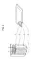
- Fig. 3 shows an example of an electrochemical capacitor using the electrode for an electricity storage device according to the present embodiment.
- Fig. 3 shows an example of a winding cell on the left side, and shows an example of a laminate cell on the right side.
- the electrochemical capacitor in Fig. 3 is provided with a positive electrode 6 on one side of a separator 5, and provided with a negative electrode 7 on the other side of the separator 5.
- a laminated body composed of the separator 5, the positive electrode 6 and the negative electrode 7 is sealed in a casing body 8 together with an electrolyte (electrolyte liquid).
- a tungsten metal flat plate as a substrate was placed in an electric furnace capable of controlling an atmosphere.
- argon containing oxygen was allowed to flow into, the temperature was increased to 100 °C at a rate of temperature rise of 550 °C/hour.
- an oxygen concentration in the flow of argon containing oxygen was 1% by volume (10000 ppm by volume), and a flow rate was 15 cm 3 /minute (1 atm, 25 °C).
- argon containing oxygen was changed to pure argon. While pure argon gas was allowed to flow into, the temperature was increased to 1100 °C at a rate of temperature rise of 550 °C/hour, and kept at 1100 °C for two hours.
- a flow rate of pure argon gas was 15 cm 3 /minute (1 atm, 25 °C).
- the supply of pure argon gas was stopped. Thereafter, the furnace was naturally cooled to room temperature, thereby obtaining an electrode for an electricity storage device of this example.
- the electrode of this example is referred to as a "sample 1".
- the color of the sample 1 was yellow.
- an average length of the whiskers formed therein was approximately 30 ⁇ m, and the electrode thus obtained had a size of 1 cm ⁇ 1 cm, and a thickness of 0.1 mm.
- Example 2 An electrode for an electricity storage device of this example was obtained by carrying out the similar operations to Example 1, except that the supply of argon gas was stopped when the temperature reached 1100 °C.
- the electrode of this example is referred to as a "sample 2".
- the color of the sample 2 was purple.
- an average length of the whiskers formed therein was approximately 30 ⁇ m, and the electrode thus obtained had a size of 1 cm ⁇ 1 cm, and a thickness of 0.1 mm.
- Example 3 An electrode for an electricity storage device of this example was obtained by carrying out the similar operations to Example 1, except that the supply of argon gas was stopped when the temperature reached 300 °C.
- the electrode of this example is referred to as a "sample 3".
- the color of the sample 3 was greenish dark blue.
- an average length of the whiskers formed therein was approximately 30 ⁇ m, and the electrode thus obtained had a size of 1 cm ⁇ 1 cm, and a thickness of 0.1 mm.
- a tungsten metal flat plate as a substrate was placed in an electric furnace capable of controlling an atmosphere. Then, heating in the furnace was started in an atmospheric state. While pure argon was supplied thereto immediately after the start of heating, the temperature was increased to 1100 °C at a rate of temperature rise of 1100 °C/hour, and kept at 1100 °C for eight hours. In this case, a flow rate of pure argon was 300 cm 3 /minute (1 atm, 25 °C). Thereafter, the furnace was naturally cooled to room temperature, thereby obtaining an electrode for an electricity storage device of this example.
- the electrode of this example is referred to as a "sample 4".
- the color of the sample 4 was purple.
- an average length of the whiskers formed therein was approximately 30 ⁇ m, and the electrode thus obtained had a size of 1 cm ⁇ 1 cm, and a thickness of 0.1 mm.
- Example 5 An electrode for an electricity storage device of this example was obtained by carrying out the similar operations to Example 4, except that the keeping time at 1100 °C was two hours.
- the electrode of this example is referred to as a "sample 5".
- the color of the sample 5 was dark blue.
- an average length of the whiskers formed therein was approximately 30 ⁇ m, and the electrode thus obtained had a size of 1 cm ⁇ 1 cm, and a thickness of 0.1 mm.
- Figs. 4 and 5 are, respectively, a graph showing a valence band photoelectron spectrum of the whisker surface and a graph showing a W4f photoelectron spectrum of the whisker surface of the respective examples 1 to 5.
- the peak intensities adjacent to the Fermi level of the sample 1 and the sample 3 were 2/43 and 1/25, which were less than 1/20, with respect to the maximum peak intensity within the range of 5 to 10 eV.
- the peak intensity adjacent to the Fermi level of the sample 4 was 4/15, which was 1/5 or more, with respect to the maximum peak intensity within the range of 5 to 10 eV.
- the peak intensities adjacent to the Fermi level of the sample 2 and the sample 5 were 1/6 and 1/11, which were 1/20 or more, with respect to the maximum peak intensity within the range of 5 to 10 eV.
- the intensity at 34 eV of each of the sample 1 and the sample 3 was 1/37, which was less than 1/20, with respect to the intensity at 36 eV.
- the intensity at 34 eV of the sample 4 was 5/11, which was 1/5 or more, with respect to the intensity at 36 eV.
- the intensities at 34 eV of the sample 2 and the sample 5 were 5/17 and 1/8, which were 1/20 or more, with respect to the intensity at 36 eV.
- Fig. 6 is a graph showing a result (reflectance spectrum) according to a visible light spectroscopic analysis of the whiskers of the respective examples.
- the other three samples did not have clearly distinguishable peaks confirmed in the graph.
- Fig. 7 is a graph showing a result (artificial transmission spectrum) obtained by a Kubelka-Munk (K-M) conversion of the reflectance spectrum of Fig. 6 . According to this spectrum, the sample 2 and the sample 4 indicated by purple were confirmed to have maximum peaks within the range of 500 to 600 nm.
- the properties of the electrodes for an electricity storage device of Example 2 and Example 5 were evaluated by a charge and discharge test and cyclic voltammetry (CV). More specifically, by use of a tripolar cell in which the electrode for an electricity storage device of respective Example 2 and Example 5 was used as a test electrode and lithium foil was used as an auxiliary electrode and a reference electrode, the cyclic voltammetry (CV) was performed to measure.
- Fig. 8 and Fig. 9 show CV curves of the electrodes for an electricity storage device of Example 2 and Example 5, respectively.
- the electrode for an electricity storage device of Example 2 shows excellent cycle resistance performance.
- the electrode of Example 2 can obtain a CV curve indicating no deterioration.
- the electrode for an electricity storage device of Example 5 can also obtain a relatively stable CV curve when the voltage range is between 1.7 and 3.0 V. However, it is confirmed that slight deterioration is caused when the voltage range is extended toward the lower potential side of 1.5 to 3.0 V
- a tungsten metal flat plate as a substrate was placed in an electric furnace capable of controlling an atmosphere. While argon containing oxygen with a high concentration was allowed to flow into, the temperature was increased to 100 °C at a rate of temperature rise of 550 °C/hour. In this case, the oxygen concentration in the flow of argon containing oxygen was 1% by volume (10000 ppm by volume), and a flow rate was 15 cm 3 /minute (1 atm, 25 °C). Then, while argon gas containing oxygen with a low concentration was allowed to flow into, the temperature was increased to 1100 °C at a rate of temperature rise of 550 °C/hour, and kept at 1100 °C for two hours.
- the oxygen concentration in the flow of argon containing oxygen was 0.05% by volume (500 ppm by volume), and a flow rate was 15 cm 3 /minute (1 atm, 25 °C).
- the current applied to the electric furnace was stopped, followed by cooling gradually. While cooling gradually, the supply of argon gas containing oxygen with a low concentration was stopped when the temperature reached 200 °C. Thereafter, the furnace was naturally cooled to room temperature, thereby obtaining an electrode for an electricity storage device of this example.
- the electrode of this example is referred to as a "sample 6".
- the color of the sample 6 was purple.
- an average length of the whiskers formed therein was approximately 30 ⁇ m, and the electrode thus obtained had a size of 1 cm ⁇ 1 cm, and a thickness of 0.1 mm.
- a tungsten metal flat plate as a substrate was placed in an electric furnace capable of controlling an atmosphere. While argon containing oxygen with a high concentration was allowed to flow into, the temperature was increased to 100 °C at a rate of temperature rise of 550 °C/hour. In this case, the oxygen concentration in the flow of argon containing oxygen was 1% by volume (10000 ppm by volume), and a flow rate was 15 cm 3 /minute (1 atm, 25 °C). Then, while argon gas containing oxygen with a low concentration was allowed to flow into, the temperature was increased to 1100 °C at a rate of temperature rise of 550 °C/hour, and kept at 1100 °C for two hours.
- the oxygen concentration in the flow of argon containing oxygen was 0.1°/a by volume (1000 ppm by volume), and a flow rate was 15 cm 3 /minute (1 atm, 25 °C).
- the current applied to the electric furnace was stopped, followed by cooling gradually. While cooling gradually, the supply of argon gas containing oxygen with a low concentration was stopped when the temperature reached 200 °C. Thereafter, the furnace was naturally cooled to room temperature, thereby obtaining an electrode for an electricity storage device of this example.
- the electrode of this example is referred to as a "sample 7".
- the color of the sample 7 was purple.
- an average length of the whiskers formed therein was approximately 30 ⁇ m, and the electrode thus obtained had a size of 1 cm ⁇ 1 cm, and a thickness of 0.1 mm.
- a tungsten metal flat plate as a substrate was placed in an electric furnace capable of controlling an atmosphere. While argon containing oxygen with a high concentration was allowed to flow into, the temperature was increased to 100 °C at a rate of temperature rise of 550 °C/hour. In this case, the oxygen concentration in the flow of argon containing oxygen was 1% by volume (10000 ppm by volume), and a flow rate was 15 cm 3 /minute (1 atm, 25 °C). Then, while argon gas containing oxygen with a low concentration was allowed to flow into, the temperature was increased to 1100 °C at a rate of temperature rise of 550 °C/hour, and kept at 1100 °C for two hours.
- the oxygen concentration in the flow of argon containing oxygen was 0.4% by volume (4000 ppm by volume), and a flow rate was 15 cm 3 /minute (1 atm, 25 °C).
- the current applied to the electric furnace was stopped, followed by cooling gradually. While cooling gradually, the supply of argon gas containing oxygen with a low concentration was stopped when the temperature reached 200 °C. Thereafter, the furnace was naturally cooled to room temperature, thereby obtaining an electrode for an electricity storage device of this example.
- the electrode of this example is referred to as a "sample 8".
- the color of the sample 8 was purple.
- an average length of the whiskers formed therein was approximately 30 ⁇ m, and the electrode thus obtained had a size of 1 cm ⁇ 1 cm, and a thickness of 0.1 mm.
- a tungsten metal flat plate as a substrate was placed in an electric furnace capable of controlling an atmosphere. While argon containing oxygen with a high concentration was allowed to flow into, the temperature was increased to 100 °C at a rate of temperature rise of 550 °C/hour. In this case, the oxygen concentration in the flow of argon containing oxygen was 1% by volume (10000 ppm by volume), and a flow rate was 15 cm 3 /minute (1 atm, 25 °C.). Then, while argon gas containing oxygen with a low concentration was allowed to flow into, the temperature was increased to 1100 °C at a rate of temperature rise of 550 °C/hour, and kept at 1100 °C for two hours.
- the oxygen concentration in the flow of argon containing oxygen was 0.6% by volume (6000 ppm by volume), and a flow rate was 15 cm 3 /minute (1 atm, 25 °C.).
- the current applied to the electric furnace was stopped, followed by cooling gradually. While cooling gradually, the supply of argon gas containing oxygen with a low concentration was stopped when the temperature reached 200 °C. Thereafter, the furnace was naturally cooled to room temperature, thereby obtaining an electrode for an electricity storage device of this example.
- the electrode of this example is referred to as a "sample 9".
- the color of the sample 9 was dark blue.
- an average length of the whiskers formed therein was approximately 30 ⁇ m, and the electrode thus obtained had a size of 1 cm ⁇ 1 cm, and a thickness of 0.1 mm.
- a tungsten metal flat plate as a substrate was placed in an electric furnace capable of controlling an atmosphere. While argon containing oxygen with a high concentration was allowed to flow into, the temperature was increased to 100 °C at a rate of temperature rise of 550 °C/hour. In this case, the oxygen concentration in the flow of argon containing oxygen was 1% by volume (10000 ppm by volume), and a flow rate was 15 cm 3 /minute (1 atm, 25 °C). Then, while argon gas containing oxygen with a low concentration was allowed to flow into, the temperature was increased to 1100 °C at a rate of temperature rise of 550 °C/hour, and kept at 1100 °C for two hours.
- the oxygen concentration in the flow of argon containing oxygen was 0.8% by volume (8000 ppm by volume), and a flow rate was 15 cm 3 /minute (1 atm, 25 °C).
- the current applied to the electric furnace was stopped, followed by cooling gradually. While cooling gradually, the supply of argon gas containing oxygen with a low concentration was stopped when the temperature reached 200 °C. Thereafter, the furnace was naturally cooled to room temperature, thereby obtaining an electrode for an electricity storage device of this example.
- the electrode of this example is referred to as a "sample 10".
- the color of the sample 10 was greenish dark blue.
- an average length of the whiskers formed therein was approximately 30 ⁇ m, and the electrode thus obtained had a size of 1 cm ⁇ 1 cm, and a thickness of 0.1 mm.
- the respective samples 6 to 10 were subjected to an X-ray photoelectron spectroscopic analysis using an X-ray photoelectron spectroscopic analyzer (QUANTUM 2000, manufactured by ULVAC-PHI Inc.) to carry out X-ray photoelectron spectroscopy.
- X-ray photoelectron spectroscopic analyzer (QUANTUM 2000, manufactured by ULVAC-PHI Inc.) to carry out X-ray photoelectron spectroscopy.
- a bipolar cell using the electrode for an electricity storage device of respective Examples 6 to 10 as a test electrode and using lithium foil as an opposite electrode was manufactured.
- EC ethylene carbonate
- DMC dimethyl carbonate
- a glass filter paper was used as a separator.
- the cells using the electrodes for an electricity storage device of Examples 6 to 10 were subjected to charge and discharge in a range of 1.2 to 3 V. First, rapid charge and discharge at 10 mA/cm 2 was carried out twice, and a capacity of the second discharge was measured. Then, charge and discharge at 1 mA/cm 2 was repeated 100 times, and a capacity maintenance ratio after 100 cycles was measured. The results thus obtained are shown in Table 1 and Fig. 10 to Fig. 13 .
- the peak intensity ratio adjacent to the Fermi level represents a ratio of a peak intensity within 1 eV from the Fermi level to a peak intensity within the range of 5 to 10 eV.
- a peak intensity ratio of 34 eV/36 eV represents a ratio of an intensity at 34 eV of a peak within the range of 33 to 34 eV to an intensity at 36 eV of a peak within the range of 35 to 36 eV.
- the asymmetry index ⁇ represents a parameter in a Doniach-Sunjic function.
- the full width at quarter maximum of the Ols peak represents a full width at quarter maximum under the peak within the range of 525 to 535 eV.
- Examples 6 to 9 particularly have excellent battery properties (rapid charge and discharge at 1 mA/cm 2 and discharge capacity maintenance ratio after 100 cycles) among Examples 6 to 10 that belong to the scope of the present invention.
- the present invention has been described above by reference to the embodiments and the examples, the present invention is not limited to those, and it will be apparent to these skilled in the art that various modifications and improvements can be made.
- the electrode for an electricity storage device may also be applied to an electrical double layer capacitor, an electrochemical capacitor, and other rechargeable electricity storage devices.
- the electrode for an electricity storage device includes a porous layer formed from fibers and/or whiskers containing tungsten oxide as a main component having a predetermined peak in a valence band photoelectron spectrum obtained by an X-ray photoelectron spectroscopic analysis. Accordingly, the electrode for an electricity storage device capable of achieving excellent performance of cycle endurance, and the electricity storage device can be provided.
Abstract
Description
- The present invention relates to an electrode for an electricity storage device and a method for manufacturing the same. More specifically, the present invention relates to an electrode for an electricity storage device including a porous layer made of fibers or whiskers containing tungsten oxide having a predetermined peak in a valence band photoelectron spectrum obtained by an X-ray photoelectron spectroscopic analysis, a method for manufacturing the same, and an electricity storage device.
- In the conventional art, an electrode for a capacitor including a porous layer made of fibers or whiskers containing tungsten oxide composed of crystals has been suggested (for example, refer to Patent Literature 1).
-
- Patent Literature 1: Japanese Patent Unexamined Publication No.
2008-103684 - However, the electrode described in Patent Literature does not have a sufficient performance of cycle endurance, and therefore, a further improvement has been required.
- The present invention has been made in view of such a conventional problem. It is an object of the present invention to provide an electrode for an electricity storage device capable of achieving excellent performance of cycle endurance, a method for manufacturing the same, and an electricity storage device.
- An electrode for an electricity storage device according to the first aspect of the present invention includes: a porous layer having either fibers or whiskers containing tungsten oxide, wherein a valence band photoelectron spectrum of the either fibers or whiskers obtained by an X-ray photoelectron spectroscopic analysis has a peak within 1 eV from a Fermi level of tungsten oxide.
- An electricity storage device according to the second aspect of the present invention includes: the electrode for an electricity storage device according to the first aspect, and an electrolyte.
- A method for manufacturing the electrode for an electricity storage device according to the third aspect of the present invention includes: heating a raw material or a substrate raw material including constituent metal of the fibers or whiskers in the presence of a small amount of oxygen so as to form either fibers or whiskers containing tungsten oxide
-
- [
Fig. 1] Fig. 1 shows one example of an electrode for an electricity storage device according to an embodiment of the present invention.Fig. 1(a) is a partial perspective view of an electrode for an electricity storage device, andFig. 1(b) is a cross-sectional view of an electrode for an electricity storage device. - [
Fig. 2] Fig. 2 is a cross-sectional view showing another example of an electrode for an electricity storage device according to an embodiment of the present invention. - [
Fig. 3] Fig. 3 is a schematic view showing an example of an electricity storage device using an electrode for an electricity storage device according to an embodiment of the present invention. - [
Fig. 4] Fig. 4 is a graph showing a valence band photoelectron spectrum of a whisker surface in an electrode for an electricity storage device of each example. - [
Fig. 5] Fig. 5 is a graph showing a W4f photoelectron spectrum of a whisker surface in an electrode for an electricity storage device of each example. - [
Fig. 6] Fig. 6 is a graph showing a result (reflectance spectrum) according to a visible light spectroscopic analysis of whiskers in an electrode for an electricity storage device of each example. - [
Fig. 7] Fig. 7 is a graph showing a result (artificial transmission spectrum) obtained by a Kubelka-Munk (K-M) conversion ofFig. 6 . - [
Fig. 8] Fig. 8 is a. graph showing a CV curve of an electrode for an electricity storage device of Example 2. - [
Fig. 9] Fig. 9 is a graph showing a CV curve of an electrode for an electricity storage device of Example 5. - [
Fig. 10] Fig. 10 is a graph showing a relation between a peak intensity ratio adjacent to a Fermi level and a battery property in Examples 6 to 10. - [
Fig. 11] Fig. 11 is a graph showing a relation between a peak intensity ratio of 34 eV/36 eV and a battery property in Examples 6 to 10. - [
Fig. 12] Fig. 12 is a graph showing a relation between an asymmetry index α and a battery property in Examples 6 to 10. - [
Fig. 13] Fig. 13 is a graph showing a relation between a full width at quarter maximum of an O1s peak and a battery property in Examples 6 to 10. - An electrode for an electricity storage device, a method for manufacturing the electrode for an electricity storage device, and an electricity storage device according to the embodiment of the present invention will be explained. In the description, a "main component" is a component of which 50% by mass or more is included relative to the total amount of constituents in each member. Note that, the dimensional ratios in the drawings are exaggerated for convenience of explanation, and may be different from the actual ratios.
- First, a specific explanation of an electrode for an electricity storage device according to the embodiment of the present invention will be made. The electrode for an electricity storage device according to the present embodiment includes a porous layer having either fibers or whiskers containing tungsten oxide. A valence band photoelectron spectrum of the fibers or the whiskers containing tungsten oxide obtained by an X-ray photoelectron spectroscopic analysis has a peak within 1 eV from a Fermi level of tungsten oxide.
- When the fibers or whiskers containing tungsten oxide has a peak within 1 eV from the Fermi level in the valence band photoelectron spectrum obtained by an X-ray photoelectron spectroscopic analysis, the fibers or whiskers can achieve excellent performance of cycle endurance. The fibers or whiskers having such a peak basically contains a PC (pentagonal column) constitution or a CS (crystallographic shear) constitution as a main component caused by oxygen defects. The PC constitution is a structural change advantageous in an atmosphere with high reducing property or under high pressure, and examples thereof include WO7, W5O14, W12O34, W17O47 and W18O49. The CS constitution is a structural change advantageous at high temperature, and the transition of the CS constitution can be controlled in a stepwise manner between WO2.88 and WO3. Examples of the CS constitution include WO3, a [102] CS constitution and a [103] CS constitution. The fibers or whiskers according to the present embodiment preferably contain a W18O49 constitution as a main component. In such a case, each function of an active material and a current collector can be achieved since the peak appears sharply.
- The "Fermi level" is a parameter determined from a condition in which a sum obtained by adding each f (ε) representing a Fermi-Dirac distribution for all ε is equivalent to the total number of particles, which represents energy in which bond energy is 0. The valence band photoelectron spectrum obtained by the X-ray photoelectron spectroscopic analysis may be measured by use of an X-ray photoelectron spectroscopic analyzer. The Fermi level can be determined by subjecting a spectrum adjacent to the Fermi level to least squares fitting using a function in which a Fermi-Dirac function of a measurement temperature in consideration of an inclination of a state density is subjected to a convolution integration by a Gaussian function with regard to an energy resolution of a device. It is to be noted that when WOx is employed, gold is measured as a reference material, and it is assumed that an energy position of the Fermi level is not changed between each measurement of WOx whiskers and gold. Then, the Fermi level is determined by fitting, and the spectrum is shifted according to the determination.
- The fibers preferably have an average diameter of approximately 0.01 µm to 1 µm, and a length of approximately 1 µm to 10 cm. The whiskers preferably have an average diameter of approximately 0.01 µm to 10 µm, and a length of approximately 1 µm to 1000 µm. The whiskers generally have a constitution composed only of shafts; however, the whiskers may have a branched constitution, a chenille constitution, or a fluff ball constitution. Basically, the whiskers can be formed at an arbitrary portion on the surface of the electrode for an electricity storage device as long as the original purpose of the electrode for an electricity storage device and other manufacturing processes are not inhibited due to the formation of the whiskers.
- In the electrode for an electricity storage device, it is preferable, but not particularly limited to, that a rising edge of the peak of the valence band photoelectron spectrum of the fibers or whiskers obtained by an X-ray photoelectron spectroscopic analysis be started before the Fermi level of tungsten oxide. When the rising edge of the peak of the spectrum is started before the Fermi level, that is, when the rising edge of the peak appears at a lower energy side than the Fermi level, the fibers or whiskers can achieve excellent performance of cycle endurance. Furthermore, the above-mentioned fibers or whiskers exert better electrical conductivity and responsiveness.
- It is preferable, but not particularly limited to, that an intensity of a peak adjacent to the Fermi level of tungsten oxide be 1/20 or more with respect to an intensity of a peak within the range of 5 to 10 eV The intensity of the peak adjacent to the Fermi level is more preferably 1/10 or more, still more preferably 1/5 or more. The peak adjacent to the Fermi level is a peak present in less than 1 eV from the Fermi level. When the intensity of the peak adjacent to the Fermi level is 1/20 or more with respect to the intensity of the peak within the range of 5 to 10 eV, more particularly, with respect to the intensity of the maximum peak adjacent to 6 eV, the electrode can ensure more favorable electrical conductivity, in addition to achieving excellent performance of cycle endurance.
- In the electrode for an electricity storage device, a W4f photoelectron spectrum of the fibers or whiskers obtained by an X-ray photoelectron spectroscopic analysis preferably has, but not particularly limited to, each peak within the range of 33 to 34 eV and within the range of 35 to 36 eV. In the spectrum within the range of 33 to 40 eV showing a 4f electron state of tungsten (W), it is confirmed that a peak derived from hexahydric tungsten (W (VI)) is detected within the range of 33 to 34 eV, and a peak derived from quadrivalent tungsten (W (IV)) is detected within the range of 35 to 36 eV. Therefore, the fibers or whiskers containing tungsten oxide in which the both peaks are detected have an extremely small abundance ratio of an oxide composed only of W (VI) or W (IV) such as WO3 and WO2. Accordingly, the above-mentioned fibers or whiskers can exert better electrical conductivity and responsiveness, in addition to achieving excellent performance of cycle endurance.
- It is preferable, but not particularly limited to, that an intensity at 34 eV of the peak within the range of 33 to 34 eV be 1/20 or more with respect to an intensity at 36 eV of the peak within the range of 35 to 36 eV. The intensity at 34 eV is more preferably 1/10 or more to 2 or less, still more preferably 1/5 or more to 1.3 or less. When the intensity at 34 eV of the peak within the range of 33 to 34 eV is 1/20 or more with respect to the intensity at 36 eV of the peak within the range of 35 to 36 eV, the electrode can ensure more favorable electrical conductivity. In addition, the intensity with 2 or less is preferable in view of an improvement in performance of cycle endurance. Moreover, when the intensity at 34 eV of the peak within the range of 33 to 34 eV is 1/10 or more with respect to the intensity at 36 eV of the peak within the range of 35 to 36 eV, better performance of cycle endurance can be achieved. Furthermore, since much better electrical conductivity and responsibility can be exerted, a rapid discharge capacity becomes large.
- Further, in the electrode for an electricity storage device, a spectrum of the fibers or whiskers obtained by a Kubelka-Munk conversion of a reflectance spectrum by a visible light spectroscopic analysis preferably has, but not particularly limited to, a maximum peak within the range of 500 to 600 nm. Due to such a maximum peak within the range of 500 to 600 nm, not only the electrode can achieve better performance of cycle endurance, but also much better electrical conductivity and responsibility can be exerted. Accordingly, the electrode can have a wider potential window (wide voltage range with stability), and ensure better quality stability.
- With regard to fibers available for a transmitted light analysis, a determination by a common visible light transmission spectrum is available. On the other hand, whiskers generally do not have a sufficient light transmission property. Thus, the whiskers are determined using a spectrum obtained by a Kubelka-Munk conversion of a spectrum in which reflected light from a light source is detected. The light source in this case is preferably a xenon light source or a halogen light source.
- Note that, the "Kubelka-Munk conversion" is a conversion using a Kubelka-Munk (K-M) function (f (R∞). The K-M function is represented by the following formula (1).
-

- However, it is difficult to measure an absolute reflectance R∞ of a sample. Therefore, in the actual measurement, a reflection intensity ratio r∞ of a sample to standard powder such as potassium bromide (KBr) and potassium chloride (KCl) adjacent to K=0 in a measuring region is measured, so as to obtain the following formula (2). Note that, the reflection intensity ratio r∞ represents r'∞ (sample)/r'∞ (standard powder), and "r'∞ (sample)" and "r'∞ (standard powder)" represent reflection intensities of a sample and standard powder, respectively.
-

- In the electrode for an electricity storage device, it is preferable, but not particularly limited to, that an asymmetry index α be 0.07 or more when a peak of the fibers or whiskers within the range of 525 to 535 eV obtained by an X-ray photoelectron spectroscopic analysis is subjected to a least squares approximation using a Doniach-Sunjic function. Note that, the peak within the range of 525 to 535 eV represents a state of Is electrons of oxygen (O). When the asymmetry index α is 0.07 or more, not only better performance of cycle endurance can be achieved, but also better electrical conductivity and responsibility can be exerted. In addition, a rapid discharge capacity becomes large.
- The Doniach-Sunjic function is represented by the following formula (3).
-

I: XPS spectrum intensity
E: XPS energy
E 0: Peak position
Γ: Peak intensity
2γ: Full width at half maximum of peak (γ: half width at half maximum)
α: Asymmetry index - This formula is a theoretical formula of a core spectrum of X-ray photoelectron spectroscopy (XPS), in which an interaction between core electrons and electrons of the Fermi level is reflected. The inventors repeated the experiments on this matter and found out that the asymmetry index α of this formula greatly contributes to a battery property. When the peak of XPS is subjected to least squares fitting by the Doniach-Sunjic function within the range of 525 to 535 eV corresponding to O1s electrons, each parameter can be obtained. The asymmetry index α representing interference between the core electrons and the electrons of the Fermi level has a strong correlation with the battery property.
- Further, in the electrode for an electricity storage device, it is preferable, but not particularly limited to, that a full width at quarter maximum under the peak of the fibers or whiskers in the peak within the range of 525 to 535 eV obtained by an X-ray photoelectron spectroscopic analysis be 2.5 to 4.0 eV. When the full width at quarter maximum under the peak is 2.5 to 4.0 eV, not only the electrode can achieve better performance of cycle endurance, but also much better electrical conductivity and responsibility can be exerted. Moreover, a rapid discharge capacity becomes large.
- As shown in
Figs. 1(a) and 1(b) , an electrode for anelectricity storage device 10 according to the present embodiment preferably includes aporous layer 1 that is made of either fibers or whiskers la and is provided on asubstrate 2 of metal or ceramics including tungsten. Due to such a configuration, excellent performance of cycle endurance can be achieved. In addition, since adhesion between the fibers orwhiskers 1a and thesubstrate 2 is further improved and an electrical contact is also improved, an internal resistance of the electrode can be reduced. Furthermore, excellent electrical conductivity and better responsibility can also be ensured. - The metal including tungsten is not limited to tungsten alone. Examples of the metal include alloys containing cobalt, chromium, manganese, iron, nickel, titanium, vanadium, niobium and molybdenum, in addition to metal and a metal compound composing whiskers or fibers containing tungsten oxide. That is, an alloy composed of tungsten and at least one of cobalt, chromium, manganese, iron, nickel, titanium, vanadium, niobium and molybdenum may be used. Examples of the ceramics include tungsten nitride, tungsten carbide and tungsten boride.
- In addition, as shown in
Fig. 2 , the substrate on which theporous layer 1 made of the fibers or whiskers is formed may include ametal layer 3 containing constituent metal of the whiskers or fibers on the surface thereof. As for the constituent metal of the whiskers or fibers, tungsten may be used as in the case of thesubstrate 2. Namely, themetal layer 3 may include tungsten alone, or include an alloy composed of tungsten and at least one of cobalt, chromium, manganese, iron, nickel, titanium, vanadium, niobium and molybdenum. Due to the constitution in which the substrate composed of tungsten metal and the like and the whiskers composed of tungsten oxide are continuously formed, not only excellent performance of cycle endurance can be achieved, but also an electrical resistance at an interface can be decreased, and therefore, excellent electrical conductivity can be ensured. In addition, a material of other compositions having an excellent physical strength and electrical conductivity may be used as acore member 4, while adhesion between the fibers or whiskers and the substrate is maintained. As a result, an internal resistance of the electrode can be reduced, and better responsibility can be exerted. Moreover, a physical strength can be improved. - Examples of the
core member 4 include metal such as iron, cobalt, nickel, niobium, molybdenum, platinum and titanium, and ceramics with a high melting point such as aluminum oxide and silicon oxide. - The
substrate 2 and thecore member 4 may be a porous body other than a flat plate as shown inFig. 1(a) and Fig. 2 . Thesubstrate 2 and thecore member 4 may employ various configurations such as metal mesh and foam metal other than a flat plate as long as the fibers or whiskers can be provided thereon. When a porous substrate is used, the substrate is preferably formed prior to the formation of the whiskers. - Next, a specific explanation of a method for manufacturing the electrode for an electricity storage device will be made. In the method for manufacturing the electrode for an electricity storage device according to the present embodiment, a raw material or substrate raw material containing constituent metal of the fibers or whiskers is subjected to a heat treatment in the presence of a small amount of oxygen, so as to form the fibers or whiskers.
- The raw material or substrate raw material may contain constituent metal of the whiskers or fibers. More specifically, a flat plate and a porous plate composed of tungsten may be used. Alternatively, a flat plate and a porous plate composed of an alloy of tungsten and at least one of cobalt, chromium, manganese, iron, nickel, titanium, vanadium, niobium and molybdenum may be used. Further, a flat plate and a porous plate provided with the
metal layer 3 and thecore member 4 shown inFig. 2 may also be used. When such a raw material is used, an electrode in which theporous layer 1 made of the whiskers or fibers and the substrate are integrated together can be formed. Namely, adhesion between the substrate and the whiskers or fibers can be improved, and therefore, an electrode for an electricity storage device having excellent performance such as electrical conductivity and responsibility can be obtained. - In the formation of the whiskers or fibers containing tungsten oxide, the raw material is heated in the presence of a small amount of oxygen, such as under an inert gas atmosphere with an oxygen concentration of 1 to 100000 ppm by volume, preferably 100 to 10 000 ppm by volume. In this case, the heating temperature is between 800 and 1600 °C, preferably between 900 and 1200 °C, and the heating time is between 1 minute and 100 hours, preferably 1 to 10 hours. As for the inert gas, argon is preferable.
- In addition, the oxygen concentration is preferably reduced in a stepwise manner or continuously. More specifically, the raw material is heated at 30 to 1100 °C for 1 minute to 100 hours while argon containing oxygen with an oxygen concentration of 100 to 10000 ppm by volume, preferably 5000 to 10000 ppm by volume, is allowed to flow into. In this case, a flow rate of argon containing oxygen is preferably 1 to 5000 cm3/minute (1 atm, 25 °C). Then, while allowing pure argon to flow into, the raw material is heated at 800 to 1600 °C for 1 minute to 100 hours. Thus, the whiskers or fibers containing tungsten oxide can be formed. A flow rate of pure argon is preferably 1 to 5000 cm3/minute (1 atm, 25 °C). The pure argon preferably has a purity of 99.5% or more, and more preferably has a purity of 99.99% or more. Note that, the supply of the pure argon may be stopped in the middle of the process.
- As another manufacturing method, heating of the raw material in air is started, simultaneously with the supply of pure argon, followed by heating at 800 to 1600 °C for 1 minute to 100 hours, so as to form the whiskers or fibers containing tungsten oxide. In this case, a flow rate of pure argon is preferably between 10 and 5000 cm3/minute (1 atm, 25 °C). That is, the raw material is placed in a reaction furnace, and thereafter heating of the raw material in air is started without deairing in the furnace. Subsequently, the temperature in the furnace is increased while supplying pure argon simultaneously with the start of heating of the raw material, and heating is kept at the above-mentioned temperature for the above-mentioned time. Thus, due to the process of continuously decreasing the oxygen concentration simultaneously with the start of heating of the raw material, followed by heating the raw material in such an oxygen concentration, the whiskers or fibers can be formed.
- As still another manufacturing method, the raw material is heated at 30 to 1100 °C for 1 minute to 10 hours while argon containing oxygen with a high oxygen concentration of 2000 to 20000 ppm by volume is allowed to flow into. In this case, a flow rate of argon with such a high oxygen concentration is preferably 1 to 5000 cm3/minute (1 atm, 25 °C). Then, while argon containing oxygen with a low oxygen concentration of 100 to 8000 ppm by volume is allowed to flow into, the raw material is heated at 800 to 1600 °C for 1 minute to 100 hours. Thus, the whiskers or fibers containing tungsten oxide can be formed. The oxygen concentration in argon containing oxygen with a low concentration should be below the oxygen concentration in argon containing oxygen with a high concentration. A flow rate of argon containing oxygen with a low concentration is preferably 1 to 5000 cm3/minute (1 atm, 25 °C). In addition, the supply of argon containing oxygen with a low concentration may be stopped in the middle of the process.
- The amount of inert gas to be introduced is determined in accordance with a size and configuration of a reaction furnace or a substrate to be used. For example, when the content of the furnace is 3 L. inert gas is preferably supplied at 0.1 to 5 L/minute.
- Next, a specific explanation of an electricity storage device according to one embodiment of the present invention will be made. The electricity storage device according to the present embodiment includes the electrode for an electricity storage device, and an electrolyte. The electricity storage device having such a configuration can achieve excellent performance of cycle endurance.
- The electrode for an electricity storage device may be applied to either a positive electrode or a negative electrode. The electrode for an electricity storage device may be used as an electrode by itself, or may be used in combination with other active materials. For example, a positive electrode may be combined with a covering layer containing an active material ensuring the content at a high potential side. In addition, a negative electrode may be combined with a covering layer containing an active material ensuring the stable content at a low potential side. Further, an identical composition may be applied to both electrodes.
- The electrolyte is not particularly limited, but may be a non-aqueous electrolysis solution. The non-aqueous electrolysis solution has a higher resistance to voltage compared to an aqueous electrolysis solution. Therefore, there is an advantage of easily obtaining a large capacity. In addition, since the non-aqueous electrolysis solution has higher viscosity and lower diffusion rate compared to an aqueous electrolysis solution, there is a great advantage available in combination with the electrode for an electricity storage device in which diffusion is smoothly performed. Specific examples of the non-aqueous electrolysis solution include an organic solution and an ionic liquid.
- Moreover, it is preferable to use a solid or gelled electrolyte for the electricity storage device. Such an electrolyte has the advantage of becoming manageable in a safety aspect and a cycle property aspect of a cell. In general, a solid or gelled electrolyte has lower ion conductivity compared to a liquid electrolyte. Therefore, there is a great advantage available in combination with the electrode for an electricity storage device having excellent responsibility. Specific examples of the solid or gelled electrolyte include a polymer electrolyte, a gel electrolyte and a solid acid electrolyte.
- Examples of the electricity storage device include an electrochemical capacitor (electrical double layer capacitor) and a lithium ion battery. The electrode for an electricity storage device according to the present embodiment may be applied to either a positive electrode or a negative electrode of a capacitor or a lithium ion battery.
Fig. 3 shows an example of an electrochemical capacitor using the electrode for an electricity storage device according to the present embodiment.Fig. 3 shows an example of a winding cell on the left side, and shows an example of a laminate cell on the right side. The electrochemical capacitor inFig. 3 is provided with a positive electrode 6 on one side of aseparator 5, and provided with a negative electrode 7 on the other side of theseparator 5. A laminated body composed of theseparator 5, the positive electrode 6 and the negative electrode 7 is sealed in acasing body 8 together with an electrolyte (electrolyte liquid). - Hereinafter, the present invention will be further explained in detail with reference to examples and comparative examples.
- First, a tungsten metal flat plate as a substrate was placed in an electric furnace capable of controlling an atmosphere. Next, while argon containing oxygen was allowed to flow into, the temperature was increased to 100 °C at a rate of temperature rise of 550 °C/hour. In this case, an oxygen concentration in the flow of argon containing oxygen was 1% by volume (10000 ppm by volume), and a flow rate was 15 cm3/minute (1 atm, 25 °C).
Then, argon containing oxygen was changed to pure argon. While pure argon gas was allowed to flow into, the temperature was increased to 1100 °C at a rate of temperature rise of 550 °C/hour, and kept at 1100 °C for two hours. A flow rate of pure argon gas was 15 cm3/minute (1 atm, 25 °C). When the temperature reached 200 °C, the supply of pure argon gas was stopped.
Thereafter, the furnace was naturally cooled to room temperature, thereby obtaining an electrode for an electricity storage device of this example. Hereinafter, the electrode of this example is referred to as a "sample 1". - When the
sample 1 was visually confirmed, the color of thesample 1 was yellow. In addition, when thesample 1 was observed using a scanning electron microscope (SEM), an average length of the whiskers formed therein was approximately 30 µm, and the electrode thus obtained had a size of 1 cm × 1 cm, and a thickness of 0.1 mm. - An electrode for an electricity storage device of this example was obtained by carrying out the similar operations to Example 1, except that the supply of argon gas was stopped when the temperature reached 1100 °C. Hereinafter, the electrode of this example is referred to as a "
sample 2". - When the
sample 2 was visually confirmed, the color of thesample 2 was purple. In addition, when thesample 2 was observed using the SEM, an average length of the whiskers formed therein was approximately 30 µm, and the electrode thus obtained had a size of 1 cm × 1 cm, and a thickness of 0.1 mm. - An electrode for an electricity storage device of this example was obtained by carrying out the similar operations to Example 1, except that the supply of argon gas was stopped when the temperature reached 300 °C. Hereinafter, the electrode of this example is referred to as a "
sample 3". - When the
sample 3 was visually confirmed, the color of thesample 3 was greenish dark blue. In addition, when thesample 3 was observed using the SEM, an average length of the whiskers formed therein was approximately 30 µm, and the electrode thus obtained had a size of 1 cm × 1 cm, and a thickness of 0.1 mm. - A tungsten metal flat plate as a substrate was placed in an electric furnace capable of controlling an atmosphere. Then, heating in the furnace was started in an atmospheric state. While pure argon was supplied thereto immediately after the start of heating, the temperature was increased to 1100 °C at a rate of temperature rise of 1100 °C/hour, and kept at 1100 °C for eight hours. In this case, a flow rate of pure argon was 300 cm3/minute (1 atm, 25 °C).
Thereafter, the furnace was naturally cooled to room temperature, thereby obtaining an electrode for an electricity storage device of this example. Hereinafter, the electrode of this example is referred to as a "sample 4". - When the
sample 4 was visually confirmed, the color of thesample 4 was purple. In addition, when thesample 4 was observed using the SEM, an average length of the whiskers formed therein was approximately 30 µm, and the electrode thus obtained had a size of 1 cm × 1 cm, and a thickness of 0.1 mm. - An electrode for an electricity storage device of this example was obtained by carrying out the similar operations to Example 4, except that the keeping time at 1100 °C was two hours. Hereinafter, the electrode of this example is referred to as a "
sample 5". - When the
sample 5 was visually confirmed, the color of thesample 5 was dark blue. In addition, when thesample 5 was observed using the SEM, an average length of the whiskers formed therein was approximately 30 µm, and the electrode thus obtained had a size of 1 cm × 1 cm, and a thickness of 0.1 mm. - The
respective samples 1 to 5 were subjected to an X-ray photoelectron spectroscopic analysis using an X-ray photoelectron spectroscopic analyzer (QUANTUM 2000, manufactured by ULVAC-PHI Inc.) to carry out X-ray photoelectron spectroscopy.Figs. 4 and5 are, respectively, a graph showing a valence band photoelectron spectrum of the whisker surface and a graph showing a W4f photoelectron spectrum of the whisker surface of the respective examples 1 to 5. - The
sample 1 and thesample 3, which were indicated by yellow and dark blue, each had only a slight peak confirmed adjacent to the Fermi level Ef. In addition, a peak adjacent to 34 eV was not confirmed in thesample 1 and thesample 3. On the other hand, thesample 5, which was indicated by the same dark blue, had a small peak confirmed adjacent to the Fermi level, and thesample 2 and thesample 4, which were indicated by purple, each had an obvious peak confirmed adjacent to the Fermi level. - In
Fig. 4 , the peak intensities adjacent to the Fermi level of thesample 1 and thesample 3 were 2/43 and 1/25, which were less than 1/20, with respect to the maximum peak intensity within the range of 5 to 10 eV. The peak intensity adjacent to the Fermi level of thesample 4 was 4/15, which was 1/5 or more, with respect to the maximum peak intensity within the range of 5 to 10 eV. In addition, the peak intensities adjacent to the Fermi level of thesample 2 and thesample 5 were 1/6 and 1/11, which were 1/20 or more, with respect to the maximum peak intensity within the range of 5 to 10 eV. - In
Fig. 5 , the intensity at 34 eV of each of thesample 1 and thesample 3 was 1/37, which was less than 1/20, with respect to the intensity at 36 eV. The intensity at 34 eV of thesample 4 was 5/11, which was 1/5 or more, with respect to the intensity at 36 eV. In addition, the intensities at 34 eV of thesample 2 and thesample 5 were 5/17 and 1/8, which were 1/20 or more, with respect to the intensity at 36 eV. - In addition, the
respective samples 1 to 5 were subjected to a visible light spectroscopic analysis. More specifically, the respective samples were irradiated with light using a high stability xenon lamp with 150 W as a light source, and the reflected light was introduced into a spectroscope, so as to measure a reflectance spectrum.Fig. 6 is a graph showing a result (reflectance spectrum) according to a visible light spectroscopic analysis of the whiskers of the respective examples. Thesample 1 indicated by yellow and thesample 3 indicated by dark blue had significant peaks. On the other hand, the other three samples did not have clearly distinguishable peaks confirmed in the graph. -
Fig. 7 is a graph showing a result (artificial transmission spectrum) obtained by a Kubelka-Munk (K-M) conversion of the reflectance spectrum ofFig. 6 . According to this spectrum, thesample 2 and thesample 4 indicated by purple were confirmed to have maximum peaks within the range of 500 to 600 nm. - Next, the properties of the electrodes for an electricity storage device of Example 2 and Example 5 were evaluated by a charge and discharge test and cyclic voltammetry (CV). More specifically, by use of a tripolar cell in which the electrode for an electricity storage device of respective Example 2 and Example 5 was used as a test electrode and lithium foil was used as an auxiliary electrode and a reference electrode, the cyclic voltammetry (CV) was performed to measure. In this case, as an electrolyte liquid, a liquid obtained by dissolving lithium perchlorate at a rate of 1 mol/L in a solvent of a mixture of ethylene carbonate (EC):dimethyl carbonate (DMC) = 50:50 (volume ratio) was used.
Fig. 8 andFig. 9 show CV curves of the electrodes for an electricity storage device of Example 2 and Example 5, respectively. - It is confirmed that the electrode for an electricity storage device of Example 2 shows excellent cycle resistance performance. In addition, even when the voltage range is extended toward the lower potential side from 1.7 to 3.0 V to 1.5 to 3.0 V, the electrode of Example 2 can obtain a CV curve indicating no deterioration.
- The electrode for an electricity storage device of Example 5 can also obtain a relatively stable CV curve when the voltage range is between 1.7 and 3.0 V. However, it is confirmed that slight deterioration is caused when the voltage range is extended toward the lower potential side of 1.5 to 3.0 V
- A tungsten metal flat plate as a substrate was placed in an electric furnace capable of controlling an atmosphere. While argon containing oxygen with a high concentration was allowed to flow into, the temperature was increased to 100 °C at a rate of temperature rise of 550 °C/hour. In this case, the oxygen concentration in the flow of argon containing oxygen was 1% by volume (10000 ppm by volume), and a flow rate was 15 cm3/minute (1 atm, 25 °C).
Then, while argon gas containing oxygen with a low concentration was allowed to flow into, the temperature was increased to 1100 °C at a rate of temperature rise of 550 °C/hour, and kept at 1100 °C for two hours. In this case, the oxygen concentration in the flow of argon containing oxygen was 0.05% by volume (500 ppm by volume), and a flow rate was 15 cm3/minute (1 atm, 25 °C). After keeping at 1100 °C for two hours, the current applied to the electric furnace was stopped, followed by cooling gradually. While cooling gradually, the supply of argon gas containing oxygen with a low concentration was stopped when the temperature reached 200 °C.
Thereafter, the furnace was naturally cooled to room temperature, thereby obtaining an electrode for an electricity storage device of this example. Hereinafter, the electrode of this example is referred to as a "sample 6". - When the sample 6 was visually confirmed, the color of the sample 6 was purple. In addition, when the sample 6 was observed using the SEM, an average length of the whiskers formed therein was approximately 30 µm, and the electrode thus obtained had a size of 1 cm × 1 cm, and a thickness of 0.1 mm.
- A tungsten metal flat plate as a substrate was placed in an electric furnace capable of controlling an atmosphere. While argon containing oxygen with a high concentration was allowed to flow into, the temperature was increased to 100 °C at a rate of temperature rise of 550 °C/hour. In this case, the oxygen concentration in the flow of argon containing oxygen was 1% by volume (10000 ppm by volume), and a flow rate was 15 cm3/minute (1 atm, 25 °C).
Then, while argon gas containing oxygen with a low concentration was allowed to flow into, the temperature was increased to 1100 °C at a rate of temperature rise of 550 °C/hour, and kept at 1100 °C for two hours. In this case, the oxygen concentration in the flow of argon containing oxygen was 0.1°/a by volume (1000 ppm by volume), and a flow rate was 15 cm3/minute (1 atm, 25 °C). After keeping at 1100 °C for two hours, the current applied to the electric furnace was stopped, followed by cooling gradually. While cooling gradually, the supply of argon gas containing oxygen with a low concentration was stopped when the temperature reached 200 °C.
Thereafter, the furnace was naturally cooled to room temperature, thereby obtaining an electrode for an electricity storage device of this example. Hereinafter, the electrode of this example is referred to as a "sample 7". - When the sample 7 was visually confirmed, the color of the sample 7 was purple. In addition, when the sample 7 was observed using the SEM, an average length of the whiskers formed therein was approximately 30 µm, and the electrode thus obtained had a size of 1 cm × 1 cm, and a thickness of 0.1 mm.
- A tungsten metal flat plate as a substrate was placed in an electric furnace capable of controlling an atmosphere. While argon containing oxygen with a high concentration was allowed to flow into, the temperature was increased to 100 °C at a rate of temperature rise of 550 °C/hour. In this case, the oxygen concentration in the flow of argon containing oxygen was 1% by volume (10000 ppm by volume), and a flow rate was 15 cm3/minute (1 atm, 25 °C).
Then, while argon gas containing oxygen with a low concentration was allowed to flow into, the temperature was increased to 1100 °C at a rate of temperature rise of 550 °C/hour, and kept at 1100 °C for two hours. In this case, the oxygen concentration in the flow of argon containing oxygen was 0.4% by volume (4000 ppm by volume), and a flow rate was 15 cm3/minute (1 atm, 25 °C). After keeping at 1100 °C for two hours, the current applied to the electric furnace was stopped, followed by cooling gradually. While cooling gradually, the supply of argon gas containing oxygen with a low concentration was stopped when the temperature reached 200 °C.
Thereafter, the furnace was naturally cooled to room temperature, thereby obtaining an electrode for an electricity storage device of this example. Hereinafter, the electrode of this example is referred to as a "sample 8". - When the
sample 8 was visually confirmed, the color of thesample 8 was purple. In addition, when thesample 8 was observed using the SEM, an average length of the whiskers formed therein was approximately 30 µm, and the electrode thus obtained had a size of 1 cm × 1 cm, and a thickness of 0.1 mm. - A tungsten metal flat plate as a substrate was placed in an electric furnace capable of controlling an atmosphere. While argon containing oxygen with a high concentration was allowed to flow into, the temperature was increased to 100 °C at a rate of temperature rise of 550 °C/hour. In this case, the oxygen concentration in the flow of argon containing oxygen was 1% by volume (10000 ppm by volume), and a flow rate was 15 cm3/minute (1 atm, 25 °C.).
Then, while argon gas containing oxygen with a low concentration was allowed to flow into, the temperature was increased to 1100 °C at a rate of temperature rise of 550 °C/hour, and kept at 1100 °C for two hours. In this case, the oxygen concentration in the flow of argon containing oxygen was 0.6% by volume (6000 ppm by volume), and a flow rate was 15 cm3/minute (1 atm, 25 °C.). After keeping at 1100 °C for two hours, the current applied to the electric furnace was stopped, followed by cooling gradually. While cooling gradually, the supply of argon gas containing oxygen with a low concentration was stopped when the temperature reached 200 °C.
Thereafter, the furnace was naturally cooled to room temperature, thereby obtaining an electrode for an electricity storage device of this example. Hereinafter, the electrode of this example is referred to as a "sample 9". - When the sample 9 was visually confirmed, the color of the sample 9 was dark blue. In addition, when the sample 9 was observed using the SEM, an average length of the whiskers formed therein was approximately 30 µm, and the electrode thus obtained had a size of 1 cm × 1 cm, and a thickness of 0.1 mm.
- A tungsten metal flat plate as a substrate was placed in an electric furnace capable of controlling an atmosphere. While argon containing oxygen with a high concentration was allowed to flow into, the temperature was increased to 100 °C at a rate of temperature rise of 550 °C/hour. In this case, the oxygen concentration in the flow of argon containing oxygen was 1% by volume (10000 ppm by volume), and a flow rate was 15 cm3/minute (1 atm, 25 °C).
Then, while argon gas containing oxygen with a low concentration was allowed to flow into, the temperature was increased to 1100 °C at a rate of temperature rise of 550 °C/hour, and kept at 1100 °C for two hours. In this case, the oxygen concentration in the flow of argon containing oxygen was 0.8% by volume (8000 ppm by volume), and a flow rate was 15 cm3/minute (1 atm, 25 °C). After keeping at 1100 °C for two hours, the current applied to the electric furnace was stopped, followed by cooling gradually. While cooling gradually, the supply of argon gas containing oxygen with a low concentration was stopped when the temperature reached 200 °C.
Thereafter, the furnace was naturally cooled to room temperature, thereby obtaining an electrode for an electricity storage device of this example. Hereinafter, the electrode of this example is referred to as a "sample 10". - When the
sample 10 was visually confirmed, the color of thesample 10 was greenish dark blue. In addition, when thesample 10 was observed using the SEM, an average length of the whiskers formed therein was approximately 30 µm, and the electrode thus obtained had a size of 1 cm × 1 cm, and a thickness of 0.1 mm. - The respective samples 6 to 10 were subjected to an X-ray photoelectron spectroscopic analysis using an X-ray photoelectron spectroscopic analyzer (QUANTUM 2000, manufactured by ULVAC-PHI Inc.) to carry out X-ray photoelectron spectroscopy.
- After the X-ray photoelectron spectroscopic analysis, a bipolar cell using the electrode for an electricity storage device of respective Examples 6 to 10 as a test electrode and using lithium foil as an opposite electrode was manufactured. As an electrolyte liquid, a liquid obtained by dissolving lithium perchlorate at a rate of 1 mol/L in a solvent of a mixture of ethylene carbonate (EC):dimethyl carbonate (DMC) = 50:50 (volume ratio) was used. In addition, a glass filter paper was used as a separator.
- The cells using the electrodes for an electricity storage device of Examples 6 to 10 were subjected to charge and discharge in a range of 1.2 to 3 V. First, rapid charge and discharge at 10 mA/cm2 was carried out twice, and a capacity of the second discharge was measured. Then, charge and discharge at 1 mA/cm2 was repeated 100 times, and a capacity maintenance ratio after 100 cycles was measured. The results thus obtained are shown in Table 1 and
Fig. 10 to Fig. 13 . - In Table 1 and
Fig. 10 , the peak intensity ratio adjacent to the Fermi level represents a ratio of a peak intensity within 1 eV from the Fermi level to a peak intensity within the range of 5 to 10 eV. In Table 1 andFig. 11 , a peak intensity ratio of 34 eV/36 eV represents a ratio of an intensity at 34 eV of a peak within the range of 33 to 34 eV to an intensity at 36 eV of a peak within the range of 35 to 36 eV. In Table 1 andFig. 12 , the asymmetry index α represents a parameter in a Doniach-Sunjic function. In Table 1 andFig. 13 , the full width at quarter maximum of the Ols peak represents a full width at quarter maximum under the peak within the range of 525 to 535 eV. -
[Table 1] Peak Intensity Ratio adjacent to Fermi Level (-) 34 eV/36 eV Peak Intensity Ratio (-) Asymmetry Index α (-) O1s Peak Full Width at 1/4 Maximum (eV) 10 mA/cm2 Rapid Discharge Capacity (mAh/cm2) Capacity Maintenance Ratio after 100 Cycles (%) Example 6 0.340 0.421 0.126 3.073 1.2 67 Example 7 0.271 0.310 0,106 2.887 1.02 58 Example 8 0.084 0.131 0.071 2.567 0.51 48 Example 9 0.074 0,134 0.071 2.535 0.45 47 Example 10 0.047 0.092 0.067 2.458 0.01 1 - According to Table 1 and
Fig. 10 to Fig. 13 , it is recognized that Examples 6 to 9 particularly have excellent battery properties (rapid charge and discharge at 1 mA/cm2 and discharge capacity maintenance ratio after 100 cycles) among Examples 6 to 10 that belong to the scope of the present invention. - The entire contents of Japanese Patent Application No.
P2009-036617 (filed on February 19, 2009 P2009-157445 (filed on July 2, 2009 - Although the present invention has been described above by reference to the embodiments and the examples, the present invention is not limited to those, and it will be apparent to these skilled in the art that various modifications and improvements can be made. For example, although the explanations have been made in the above-described examples in the case of applying the electrode for an electricity storage device to a lithium ion battery, the electrode for an electricity storage device may also be applied to an electrical double layer capacitor, an electrochemical capacitor, and other rechargeable electricity storage devices.
- The electrode for an electricity storage device according to the present invention includes a porous layer formed from fibers and/or whiskers containing tungsten oxide as a main component having a predetermined peak in a valence band photoelectron spectrum obtained by an X-ray photoelectron spectroscopic analysis. Accordingly, the electrode for an electricity storage device capable of achieving excellent performance of cycle endurance, and the electricity storage device can be provided.
-
- 1
- Porous layer
- 1a
- Fiber, whisker
- 2
- Substrate
- 3
- Metal layer
- 4
- Core member
- 5
- Separator
- 6
- Positive electrode
- 7
- Negative electrode
- 8
- Casing body
Claims (14)
- An electrode for an electricity storage device, comprising:a porous layer having either fibers or whiskers containing tungsten oxide,wherein a valence band photoelectron spectrum of the fibers or whiskers obtained by an X-ray photoelectron spectroscopic analysis has a peak within 1 eV from a Fermi level of tungsten oxide.
- The electrode for an electricity storage device according to claim 1, wherein a rising edge of the peak of the valence band photoelectron spectrum of the fibers or whiskers obtained by the X-ray photoelectron spectroscopic analysis is started before the Fermi level of tungsten oxide, and an intensity of the peak within 1 eV is 1/20 or more with respect to an intensity of a peak within a range of 5 to 10 eV.
- The electrode for an electricity storage device according to claim 1 or 2. wherein a W4f photoelectron spectrum of the fibers or whiskers obtained by the X-ray photoelectron spectroscopic analysis has each peak within a range of 33 to 34 eV and within a range of 35 to 36 eV.
- The electrode for an electricity storage device according to claim 3, wherein an intensity at 34 eV of the peak within the range of 33 to 34 eV is 1/20 or more with respect to an intensity at 36 eV of the peak within the range of 35 to 36 eV.
- The electrode for an electricity storage device according to claim 4, wherein the intensity at 34 eV of the peak within the range of 33 to 34 eV is 1/10 or more with respect to the intensity at 36 eV of the peak within the range of 35 to 36 eV.
- The electrode for an electricity storage device according to any one of claims 1 to 5, wherein a spectrum of the fibers or whiskers obtained by a Kubelka-Munk conversion of a reflectance spectrum by a visible light spectroscopic analysis has a maximum peak within a range of 500 to 600 nm.
- The electrode for an electricity storage device according to any one of claims 1 to 6, wherein when a peak of the fibers or whiskers within a range of 525 to 535 eV obtained by the X-ray photoelectron spectroscopic analysis is subjected to a least squares approximation using a Doniach-Sunjic function, an asymmetry index α is 0.07 or more.
- The electrode for an electricity storage device according to any one of claims 1 to 7, wherein a full width at quarter maximum under the peak of the fibers or whiskers within the range of 525 to 535 eV obtained by the X-ray photoelectron spectroscopic analysis is within a range of 2.5 to 4.0 eV.
- The electrode for an electricity storage device according to any one of claims 1 to 8, wherein the porous layer is formed on a substrate of metal or ceramics containing tungsten.
- The electrode for an electricity storage device according to any one of claims 1 to 8, wherein the porous layer is formed on a substrate including a metal layer formed on a surface thereof containing constituent metal of the fibers or whiskers.
- An electricity storage device comprising the electrode for an electricity storage device according to any one of claims 1 to 10 and an electrolyte.
- The electricity storage device according to claim 11. wherein the electrolyte is a non-aqueous electrolysis solution.
- The electricity storage device according to claim 11, wherein the electrolyte is a solid or gelled body.
- A method for manufacturing the electrode for an electricity storage device according to any one of claims 1 to 10, comprising:heating a raw material or a substrate raw material including constituent metal of the fibers or whiskers in the presence of a small amount of oxygen so as to form either fibers or whiskers containing tungsten oxide.
Applications Claiming Priority (3)
| Application Number | Priority Date | Filing Date | Title |
|---|---|---|---|
| JP2009036617 | 2009-02-19 | ||
| JP2009157445A JP5561514B2 (en) | 2009-02-19 | 2009-07-02 | Electrode for electricity storage device and method for producing the same |
| PCT/JP2010/052536 WO2010095711A1 (en) | 2009-02-19 | 2010-02-19 | Electricity storage device electrode and manufacturing method for same |
Publications (2)
| Publication Number | Publication Date |
|---|---|
| EP2400584A1 true EP2400584A1 (en) | 2011-12-28 |
| EP2400584A4 EP2400584A4 (en) | 2013-12-04 |
Family
ID=42633990
Family Applications (1)
| Application Number | Title | Priority Date | Filing Date |
|---|---|---|---|
| EP10743836.8A Withdrawn EP2400584A4 (en) | 2009-02-19 | 2010-02-19 | Electricity storage device electrode and manufacturing method for same |
Country Status (6)
| Country | Link |
|---|---|
| US (1) | US20110297419A1 (en) |
| EP (1) | EP2400584A4 (en) |
| JP (1) | JP5561514B2 (en) |
| KR (1) | KR101362528B1 (en) |
| CN (1) | CN102326281A (en) |
| WO (1) | WO2010095711A1 (en) |
Families Citing this family (3)
| Publication number | Priority date | Publication date | Assignee | Title |
|---|---|---|---|---|
| JP6058418B2 (en) * | 2012-03-26 | 2017-01-11 | 株式会社東芝 | Storage battery substrate and storage battery |
| CN106688129B (en) * | 2014-09-11 | 2020-01-31 | 株式会社东芝 | Electrode material, and electrode layer, battery and electrochromic element using same |
| JP2016076400A (en) * | 2014-10-07 | 2016-05-12 | 富士通株式会社 | Evaluation method, evaluation device, and evaluation program |
Citations (3)
| Publication number | Priority date | Publication date | Assignee | Title |
|---|---|---|---|---|
| US6093503A (en) * | 1992-09-01 | 2000-07-25 | Nippondenso Co., Ltd. | Non-aqueous electrolyte lithium secondary cell |
| WO2008035627A1 (en) * | 2006-09-21 | 2008-03-27 | Nissan Motor Co., Ltd. | Capacitor electrode and method for manufacturing the same |
| JP2008181763A (en) * | 2007-01-24 | 2008-08-07 | Nissan Motor Co Ltd | Lithium ion secondary battery using tungsten oxide whisker or fiber |
Family Cites Families (13)
| Publication number | Priority date | Publication date | Assignee | Title |
|---|---|---|---|---|
| DE2025142A1 (en) * | 1969-05-23 | 1971-01-21 | Kabushiki Kaisha Suwa Seikosha, Tokio | Method for producing contact springs for contact detectors |
| JP2004146350A (en) * | 2002-08-28 | 2004-05-20 | Sii Micro Parts Ltd | Nonaqueous electrolyte secondary battery |
| US7754382B2 (en) * | 2003-07-30 | 2010-07-13 | Tdk Corporation | Electrochemical capacitor having at least one electrode including composite particles |
| JP4347631B2 (en) * | 2003-07-30 | 2009-10-21 | Tdk株式会社 | Method for producing composite particle for electrode of electrochemical capacitor, method for producing electrode, and method for producing electrochemical capacitor |
| JP2005101141A (en) * | 2003-09-24 | 2005-04-14 | Renesas Technology Corp | Semiconductor integrated circuit device and its manufacturing method |
| JP2006164689A (en) * | 2004-12-06 | 2006-06-22 | Enerstruct Kk | Electrode structure, secondary battery, and capacitor |
| US8034408B2 (en) * | 2006-09-08 | 2011-10-11 | GM Global Technology Operations LLC | One-dimensional metal and metal oxide nanostructures |
| JP2008117905A (en) * | 2006-11-02 | 2008-05-22 | Gs Yuasa Corporation:Kk | Electrochemical capacitor |
| JP4753141B2 (en) | 2007-08-01 | 2011-08-24 | 独立行政法人 日本原子力研究開発機構 | Method for dissolving and separating uranium using ionic liquid, and method for recovering uranium using the same |
| JP5046110B2 (en) * | 2007-11-08 | 2012-10-10 | 日産自動車株式会社 | Method for producing metal oxide fiber material formed body |
| JP2009157445A (en) | 2007-12-25 | 2009-07-16 | Ricoh Co Ltd | Database development management system and program |
| BRPI0920052A2 (en) * | 2008-10-27 | 2015-12-15 | School Corp Kansai Univ | composite electrode for electricity storage device, method for producing it and electricity storage device |
| KR20170003728A (en) * | 2009-04-13 | 2017-01-09 | 어플라이드 머티어리얼스, 인코포레이티드 | Composite materials containing metallized carbon nanotubes and nanofibers |
-
2009
- 2009-07-02 JP JP2009157445A patent/JP5561514B2/en not_active Expired - Fee Related
-
2010
- 2010-02-19 CN CN2010800083589A patent/CN102326281A/en active Pending
- 2010-02-19 EP EP10743836.8A patent/EP2400584A4/en not_active Withdrawn
- 2010-02-19 US US13/201,697 patent/US20110297419A1/en not_active Abandoned
- 2010-02-19 KR KR1020117019151A patent/KR101362528B1/en not_active IP Right Cessation
- 2010-02-19 WO PCT/JP2010/052536 patent/WO2010095711A1/en active Application Filing
Patent Citations (3)
| Publication number | Priority date | Publication date | Assignee | Title |
|---|---|---|---|---|
| US6093503A (en) * | 1992-09-01 | 2000-07-25 | Nippondenso Co., Ltd. | Non-aqueous electrolyte lithium secondary cell |
| WO2008035627A1 (en) * | 2006-09-21 | 2008-03-27 | Nissan Motor Co., Ltd. | Capacitor electrode and method for manufacturing the same |
| JP2008181763A (en) * | 2007-01-24 | 2008-08-07 | Nissan Motor Co Ltd | Lithium ion secondary battery using tungsten oxide whisker or fiber |
Non-Patent Citations (2)
| Title |
|---|
| FIGUEROA ET AL: "WO3 pillar-type and helical-type thin film structures to be used in microbatteries", JOURNAL OF POWER SOURCES, ELSEVIER SA, CH, vol. 172, no. 1, 20 September 2007 (2007-09-20), pages 422-427, XP022260090, ISSN: 0378-7753, DOI: 10.1016/J.JPOWSOUR.2007.05.080 * |
| See also references of WO2010095711A1 * |
Also Published As
| Publication number | Publication date |
|---|---|
| EP2400584A4 (en) | 2013-12-04 |
| JP5561514B2 (en) | 2014-07-30 |
| KR101362528B1 (en) | 2014-02-13 |
| US20110297419A1 (en) | 2011-12-08 |
| CN102326281A (en) | 2012-01-18 |
| JP2010219022A (en) | 2010-09-30 |
| WO2010095711A1 (en) | 2010-08-26 |
| KR20110105008A (en) | 2011-09-23 |
Similar Documents
| Publication | Publication Date | Title |
|---|---|---|
| Li et al. | A high-rate, high-capacity, nanostructured Sn-based anode prepared using sol-gel template synthesis | |
| Shao et al. | Enhanced ionic conductivity of titanium doped Li7La3Zr2O12 solid electrolyte | |
| EP3543781B1 (en) | Lithium metal oxide materials for electrochromic devices | |
| Yan et al. | Understanding the fast lithium storage performance of hydrogenated TiO 2 nanoparticles | |
| EP3248233B1 (en) | Lithium metal oxide cathode powders for high voltage lithium-ion batteries | |
| EP2400586B1 (en) | Carbon material for lithium ion secondary batteries | |
| EP2352192B1 (en) | Negative electrode material for nonaqueous secondary battery | |
| Lu et al. | High switching speed and coloration efficiency of titanium-doped vanadium oxide thin film electrochromic devices | |
| JP7093588B2 (en) | A method for producing a composite solid electrolyte membrane, and an all-solid-state lithium battery using the composite solid electrolyte membrane. | |
| Le et al. | Highly efficient and stable solid-state Li–O 2 batteries using a perovskite solid electrolyte | |
| CN110510674B (en) | Electrode material for battery, substrate for battery, storage battery, dye-sensitized solar cell, capacitor, and Li-ion secondary battery | |
| CN112447967B (en) | Positive electrode active material, positive electrode plate and lithium ion secondary battery | |
| RU2761772C1 (en) | Electrochromic material and method for manufacture thereof | |
| RU2465691C1 (en) | Composite electrode for power accumulation device, method of its production and power accumulation device | |
| Tomita et al. | Comparative Performance of Anode-Supported SOFCs Using a Thin Ce0. 9Gd0. 1O1. 95 Electrolyte with an Incorporated BaCe0. 8Y0. 2O3− α Layer in Hydrogen and Methane | |
| Wu et al. | Graphene quantum dots as a highly efficient electrocatalyst for lithium–oxygen batteries | |
| Forslund et al. | Comparison of perovskite and perovskite derivatives for use in anion-based pseudocapacitor applications | |
| Yang et al. | A topochemically constructed flexible heterogeneous vanadium-based electrocatalyst for boosted conversion kinetics of polysulfides in Li–S batteries | |
| EP2400584A1 (en) | Electricity storage device electrode and manufacturing method for same | |
| Oswald et al. | Elucidating the implications of morphology on fundamental characteristics of nickel-rich NCMs: cracking, gassing, rate capability, and thermal stability of poly-and single-crystalline NCM622 | |
| Zhang et al. | Improved electrochemical properties of the Li3V2 (PO4) 3 cathode material synthesized from a V (III) precursor | |
| KR102179502B1 (en) | Lithium ion battery iron oxide electrode having a three-dimensional ant-nest network structure | |
| KR102179504B1 (en) | Preparing method of SiO2/TiO2 composite electrode for lithium ion battery with high capacitance as plasma electrolytic oxidation | |
| CN115472838A (en) | Cathode material, preparation method thereof and lithium ion battery | |
| Kashani et al. | Study of counter electrodes as an effective controlling factor of crystal orientation of TiO 2 nanoarrays used as the anode in lithium-ion batteries |
Legal Events
| Date | Code | Title | Description |
|---|---|---|---|
| PUAI | Public reference made under article 153(3) epc to a published international application that has entered the european phase |
Free format text: ORIGINAL CODE: 0009012 |
|
| 17P | Request for examination filed |
Effective date: 20110919 |
|
| AK | Designated contracting states |
Kind code of ref document: A1 Designated state(s): AT BE BG CH CY CZ DE DK EE ES FI FR GB GR HR HU IE IS IT LI LT LU LV MC MK MT NL NO PL PT RO SE SI SK SM TR |
|
| DAX | Request for extension of the european patent (deleted) | ||
| A4 | Supplementary search report drawn up and despatched |
Effective date: 20131105 |
|
| RIC1 | Information provided on ipc code assigned before grant |
Ipc: H01M 4/36 20060101ALN20131029BHEP Ipc: H01M 10/0525 20100101ALN20131029BHEP Ipc: H01G 11/50 20130101ALI20131029BHEP Ipc: H01M 4/485 20100101ALI20131029BHEP Ipc: H01M 10/052 20100101ALI20131029BHEP Ipc: H01M 4/66 20060101ALI20131029BHEP Ipc: H01M 4/131 20100101AFI20131029BHEP |
|
| STAA | Information on the status of an ep patent application or granted ep patent |
Free format text: STATUS: THE APPLICATION IS DEEMED TO BE WITHDRAWN |
|
| 18D | Application deemed to be withdrawn |
Effective date: 20140603 |