EP2400511A1 - Modular non-circular coil for transformers - Google Patents
Modular non-circular coil for transformers Download PDFInfo
- Publication number
- EP2400511A1 EP2400511A1 EP10167489A EP10167489A EP2400511A1 EP 2400511 A1 EP2400511 A1 EP 2400511A1 EP 10167489 A EP10167489 A EP 10167489A EP 10167489 A EP10167489 A EP 10167489A EP 2400511 A1 EP2400511 A1 EP 2400511A1
- Authority
- EP
- European Patent Office
- Prior art keywords
- coil
- transformer
- segments
- coils
- cross
- Prior art date
- Legal status (The legal status is an assumption and is not a legal conclusion. Google has not performed a legal analysis and makes no representation as to the accuracy of the status listed.)
- Withdrawn
Links
Images


Classifications
-
- H—ELECTRICITY
- H01—ELECTRIC ELEMENTS
- H01F—MAGNETS; INDUCTANCES; TRANSFORMERS; SELECTION OF MATERIALS FOR THEIR MAGNETIC PROPERTIES
- H01F27/00—Details of transformers or inductances, in general
- H01F27/28—Coils; Windings; Conductive connections
- H01F27/30—Fastening or clamping coils, windings, or parts thereof together; Fastening or mounting coils or windings on core, casing, or other support
- H01F27/303—Clamping coils, windings or parts thereof together
-
- H—ELECTRICITY
- H01—ELECTRIC ELEMENTS
- H01F—MAGNETS; INDUCTANCES; TRANSFORMERS; SELECTION OF MATERIALS FOR THEIR MAGNETIC PROPERTIES
- H01F27/00—Details of transformers or inductances, in general
- H01F27/28—Coils; Windings; Conductive connections
- H01F27/2871—Pancake coils
-
- H—ELECTRICITY
- H01—ELECTRIC ELEMENTS
- H01F—MAGNETS; INDUCTANCES; TRANSFORMERS; SELECTION OF MATERIALS FOR THEIR MAGNETIC PROPERTIES
- H01F27/00—Details of transformers or inductances, in general
- H01F27/28—Coils; Windings; Conductive connections
- H01F27/30—Fastening or clamping coils, windings, or parts thereof together; Fastening or mounting coils or windings on core, casing, or other support
- H01F27/306—Fastening or mounting coils or windings on core, casing or other support
-
- H—ELECTRICITY
- H01—ELECTRIC ELEMENTS
- H01F—MAGNETS; INDUCTANCES; TRANSFORMERS; SELECTION OF MATERIALS FOR THEIR MAGNETIC PROPERTIES
- H01F27/00—Details of transformers or inductances, in general
- H01F27/28—Coils; Windings; Conductive connections
- H01F27/32—Insulating of coils, windings, or parts thereof
- H01F27/324—Insulation between coil and core, between different winding sections, around the coil; Other insulation structures
Definitions
- the invention relates to coils of transformers.
- the invention relates to a coil for a transformer and a transformer with the coil.
- the patent application WO-98/10445 describes the separate manufacturing of insulated single disks, their stacking, and the over-moulding of the complete stack with a solid insulation for forming a transformer.
- Small transformers from 50 VA up to 3 kVA are encapsulated by a thermoplastic material.
- a coil for a transformer comprising a plurality of coil segments of a modular type, each of which having a uniform cross-section.
- Each coil segment is electrically connected to another coil segment of the plurality of coil segments forming a coil segment stack or the coil, the stack defining a stack axis.
- the uniform cross-section of each of the plurality of coil segments is a non-circular cross-section and the cross-section is in a plane perpendicular to the stack axis.
- Such a coil may provide for considerable cost-savings, especially, for example, for transformers with low ratings. These cost-savings may be provided mainly from faster production cycles compared to a production of a single non-modular coil or in other words one coil body.
- the coil as described above may provide a high degree of standardization concerning the manufacturing of the coil enabling variable sizing of the coil and thus time and cost savings compared to a manufacturing of a non-modular coil which is generally designed for manufacturing a defined size of a transformer.
- the coil with the non-circular cross-section may further enable a reduction of the core steel, as the distance between phases of a transformer may be reduced and thereby less core steel may be used, also if the cores are stacked, for example of cut metal sheets.
- a coil with coil segments with a uniform non-circular cross-section as described above may enable a faster manufacturing of the core of the transformer. Manufacturing a non-circular core by conventional stacking of cut metal sheets may be more efficient than manufacturing a circular core since all metal sheets may have the same width. Furthermore the transformer with a non-circular cross-section may be built more compact compared to a core with a circular cross-section.
- the coil may be a modular coil and the transformer may be a dry transformer or a dry distribution transformer.
- the coil segment may be a modular disk or a disk.
- the disk or modular disk may comprise a supporting device with a thereto wound conductor, wherein an insulation material may be attached to the supporting device and the conductor for insulating the supporting device and the conductor.
- the electrical connecting of the coil segments to each other may comprise the steps of removing enamel of the connecting means at each coil segment of the plurality of coil segments and crimping the connecting means of each coil segment of the plurality of coil segments to a connecting means of an adjacent coil segment of the plurality of coil segments.
- the coil segment comprises at least one high voltage (HV) coil segment.
- HV high voltage
- the coil segment comprises at least one low voltage (LV) coil segment.
- LV low voltage
- a coil with coil segments of a modular type or in other words a coil of a modular type means that HV and/or LV windings may be adapted as disc windings which may be moulded and which may have two connections or terminals such that the disc windings are stackable.
- High voltage and low voltage coils may be combined in one coil segment according to another embodiment of the invention.
- high voltage coils may be in one coil segment and only low voltage coils may be in one coil segment.
- the high voltage coil may be arranged at a secondary possibly low voltage coil comprising a secondary or low voltage coil conductor in insulating material.
- the non-circular cross-section is a cross-section selected from the group consisting of a rectangular, a hexagonal, an oval, and a polygonal cross-section.
- a coil with a non-circular cross-section or an oval cross-section may provide for a compact modular arrangement of the cores of the transformer and the transformer itself.
- each of the plurality of coil segments comprises a conductor, a supporting device for supporting the conductor being wound around the supporting device, and an insulation material for insulating the conductor.
- the insulation material may be moulded around the conductor and the supporting device.
- the insulation material may be adapted for electromagnetically insulating the coil segment.
- the insulation material may be a thermoplastic material instead of a thermosetting material which may make a curing cycle unnecessary when manufacturing the transformer, thus decreasing the production time of the transformer.
- a thermoplastic material instead of a thermosetting material which may make a curing cycle unnecessary when manufacturing the transformer, thus decreasing the production time of the transformer.
- material costs and depreciation during five years cost-savings of up to 50% may be expected by manufacturing a transformer with the above-mentioned coil compared to manufacturing the transformer with a non-modular coil.
- Thermoplastic resins with a higher thermo-conductivity would allow using the modular concept of the coil of the transformer also for transformers with high power.
- the modular concept of a coil with coil segments of a modular type may enable the use of a two-compound injection moulding process enabling to have one field grading compound, smoothing the electrical field around the conductor and thereby allowing for the distance between high voltage and low voltage coils of the transformer to be reduced.
- the supporting device may have a ring form with two sidewalls, in other words the supporting device may be a ring with a U-shaped cross-section.
- the supporting device may have a non-circular form such as one of a rectangular, a non-circular, and a hexagonal form.
- a field control layer arrangement for reducing the maximum field strength of an electric field generated in the coil is provided.
- a first field control layer of the field control layer arrangement is applied at edges of the coil segment.
- the field control layer arrangement may have a high permittivity material with a permittivity of about 10, and the insulation material may have a low permittivity.
- the field control layer arrangement may be injection-moulded around the conductor.
- the field control layer arrangement may reduce the maximum field strength of the coil by 50% compared to a coil without a field control layer arrangement and refractive field control may be provided by the field control layer arrangement.
- the field control layer arrangement may comprise a material selected from the group consisting of a composite material with TiO2, ZnO or BaTiO3 filler. Due to the difference in permittivity between the grading layer and the insulation material, the electric field concentrates in the insulation material and is reduced at the with high permittivity layer coated coil corners or coil edges.
- the permittivity ratio of the insulation material to the field control layer arrangement is 1 to 1.5-20, in particular 1 to 2-5 thereby controlling the electric field.
- Such a refractive field control or control of the electric field may be achieved by a specific arrangement of materials with different permittivity; for example materials or devices with a permittivity ratio of 1 to 1.5-20, particularly 1 to 2-5, may be arranged adjacent to each other or over one another thereby enabling the refractive field control or control of the electric field generated in the coil.
- a first field control layer of the field control layer arrangement is applied at edges of the coil body.
- the first field control layer may be applied at the inner edges of the coil body facing another coil body, such as a LV coil, for example, and/or at the outer edges of the coil body.
- the first field control layer may comprise rounded edges and may have the same features as the above mentioned features of the field control layer arrangement.
- the coil further comprises at least one second field control layer of the field control layer arrangement.
- the supporting device comprises at least one of the at least one second field control layer.
- the at least one second field control layer may be a high epsilon layer.
- the at least one second field control layer may have the same features as the above mentioned features of the field control layer arrangement.
- the coil may further comprise a locking means for preventing rotation of adjacent coil segments of the plurality of coil segments.
- locking means a locking system or locking arrangement is meant that may comprise more than one locking devices.
- the locking means comprises a through-hole in each of the plurality of coil segments and a rod being adapted to pass through the through-hole of each of the plurality of coil segments.
- the rod may be a threaded rod fitting to threads in the through-holes.
- Two through-holes may be arranged on opposite sides of the coil segments and two rods may each pass through one of the two through-holes preventing the coil segments from rotating among each other.
- the locking means comprises a latch arranged at each of the plurality of coil segments in a recess arranged at each of the plurality of coil segments such that the latch of the coil segments of the plurality of coil segments is adapted to fit to the recess of an adjacent coil segment of the plurality of coil segments.
- Such a latch-recess locking mechanism may prevent the rotation of the coil segments among each other efficiently, wherein each coil segment may be easily stacked to another coil segment.
- There may be more than one recess and more than one latch arranged at each of the coil segments.
- Eight latches and eight recesses may be arranged equispaced at each of the coil segments.
- the recess and the latch may be part of the coil segment and both may have one of a circular, a rectangular, a polygonal, a non-circular, a hexagonal, and a triangular form.
- the latch may be pin-like and the recess may be hole-like.
- the locking means comprises a snap-fit connection arranged at adjacent coil segments of the plurality of coil segments.
- the snap-fit connection may comprise a clamp and a matching counterpart being arranged at each of the plurality of coil segments.
- There may be a plurality of clamps and counterparts arranged at each of the plurality of coil segments, for example three clamps and three counterparts per coil segment.
- the coil further comprises a guiding element for the electrical connection, e.g. in form of a clamp connecting or crimp connecting the plurality of coil segments and for clamp or crimp connecting the coil segments to a further coil of a transformer.
- the guiding element may be arranged at each of the conductors of the plurality of coil segments.
- the conductor is in form of a foil wound around the supporting device enabling a faster manufacturing of the coil compared to a manufacturing of the coil wherein the conductor is in form of a wire wound around the supporting device being a further embodiment of the invention.
- the coil body is a high voltage coil body and an insulation material is attached to a low voltage coil.
- the high voltage coil body is combined with the low voltage coil body surrounding a core of the transformer.
- the insulation material may be moulded to the low voltage coil.
- a transformer having a first coil of anyone of the above-mentioned embodiments, the transformer further comprising a core having a cross-section corresponding to the non-circular cross-section of each of a plurality of coil segments of the first coil.
- the core may comprise one of a rectangular, a hexagonal, an oval and a non-circular form or combination thereof.
- the core may generally have a non-circular form.
- the core is an amorphous core.
- the core may be built from thin sheets which are insulated against each other for minimizing the losses from eddy currents.
- Standard core steel usually low C content of less than 0.1% and alloyed with Si of usually less than 3%
- grain oriented core steel wherein the cold rolling of steel orients the magnetic domains which leads to good loss properties in the rolling direction
- amorphous core steel usually low C content of less than 0.1% and alloyed with Si of usually less than 3%
- the core of the transformer may be be stacked or wound, wherein the core may be wound around the mandrel in a first step, cut at one position in a second step, spread/open up for placing the low voltage and high voltage of the transformer in a third step, and the low voltage and high voltage coils may be placed at the core in a fourth step.
- Four equal wound cores of a transformer may be arranged next to each other being combined by three high voltage and low voltage coils forming the transformer.
- Two equal wound small cores and one large wound core could be combined by three high voltage and low voltage coils forming a transformer according to a further embodiment.
- the transformer further comprises a second coil of anyone of the above-mentioned embodiments and a third coil of anyone of the above-mentioned embodiments, wherein each of the first, second and third coils surrounds the core.
- the first, second and third coils are arranged in a triangular way next to each other forming a compact transformer.
- the transformer with triangular arrangement of the coils may provide a greater mechanical stability and a more compact design compared to transformers with coils with a circular cross-section, and also compared to a linear arrangement of the coils.
- a triangular arrangement of coils with a circular cross-section may provide for a minimized distance of the coil axes to each other and thus a better mechanical stability and space-saving compared to a linear arrangement of coils with a non-circular cross-section.
- the transformer further comprises a second coil of anyone of the above-mentioned embodiments and a third coil of anyone of the above-mentioned embodiments, wherein each of the first, second and third coils surrounds the core.
- the first, second and third coils are arranged in a linear way next to each other forming a compact transformer.
- Such a transformer with a linear arrangement of coils with non-circular cross-sections in a plane perpendicular to the transformer axes or to the core limbs may be built more compact due to a possible more room saving arrangement of the non-circular cross-section coils, for example at edges of the coils, compared to a linear arrangement of coils with circular cross-sections.
- a transformer with a plurality of coils may be arranged next to each other in the most compact room-saving way depending on the non-circular shape of the cross-section of each of the plurality of coil segments of the plurality of coils such as a triangular way for a hexagonal, and for an oval-cross section or for a cross-section comprising a combination of a non-circular and a circular cross-section.
- the plurality of coils may be arranged in line, for example three coils next to each other, forming a transformer, wherein each coil segment of the plurality of coil segments of the plurality of coils of the transformer may have one of a rectangular, hexagonal, oval, non-circular, and polygonal form, or a combination of a circular and a non-circular form.
- Each core may be surrounded by a low voltage coil which is surrounded by a high voltage coil.
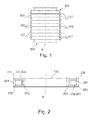
- Fig. 1 depicts a cross-sectional view of one phase of a transformer with a coil 100.
- the coil 100 comprises a plurality of coil segments 102 of a modular type, each of which having a uniform cross-section.
- Each coil segment 102 is electrically connected to another coil segment 102 of the plurality of coil segments 102 forming a coil segment stack 100, the stack 100 defining a stack axis A, or in other words the coil 100.
- Electrical connections or guiding elements 103 for clamp connecting the plurality of coil segments 102 and for clamp connecting the coil segment stack 100 to a further core of another transformer are provided and may ensure the electrical connection of the coil segments 102 to each other.
- a non-circular part of a core 104 of the transformer is surrounded by the coil 100.
- the uniform cross section of each of the plurality of coil segments 102 is a non-circular cross-section and the cross-section is in a plane perpendicular to the stack axis A.
- Fig. 2 shows a non-circular cross-section of a coil segment 102 of Fig. 1 , the cross-section being in a plane perpendicular to the stack axis A.
- the coil segment 102 comprises a conductor 201 which is supported by supporting device 202, wherein the conductor 201 may be wound around the supporting device 202.
- An insulation material 203 is surrounding the conductor 201 and the supporting device 202 and may be used for an electrical insulation of the conductor.
- the supporting device 202 has a U-shape in the form of a ring 205 with sidewalls.
- the supporting device 202 may be moulded by a two compound injection moulding process allowing to have one field grading compound, smoothing the electrical field around the conductor 201 and thereby allowing for a distance between high voltage and low voltage coils to be reduced and a second compound of a material selected form the group consisting of a thermoset and a thermoplast.
- the supporting device 202 may comprise a second field control layer 204 for reducing the maximum field strength of the electric field generated in the coil 100.
- the conductor 201 may form a winding 201 wherein a second field control layer may be applied directly at edges 205 of the coil segment 102.
- the supporting device 202 may comprise high permittivity thermoplastic.
- the insulation material 203 may be attached or impregnated or moulded to the conductor 201 and the supporting device 202 by first over-moulding or attaching the conductor 201, then over-moulding or attaching the sidewalls of the supporting device 202 in form of a ring 202, and third by over-moulding or attaching an inner wall of the ring 202 with the insulation material 203.
- Fig. 3A schematically shows a coil 100 with a plurality of coil bodies 102, wherein a first field control layer 301 is applied at edges 205 of each of the plurality of coil segments 102. Insulation material 203 is attached or moulded over each of the coil segments 102.
- Fig. 1A depicts a field control layer arrangement 200 for reducing the maximum field strength of the electric field generated in the coil 100. A first field control layer 301 of the field control layer arrangement 200 is applied at edges 205 of the coil body 102.
- One first field control layer 301 may be applied at inner edges 205 facing another coil body (not shown), such as a low voltage coil attached or moulded by an insulation material to a low voltage coil body, and an additional first field control layer 301 may be applied at outer edges 205 not-facing the adjacent low voltage coil body.
- the first field control layer 301 may also be arranged circumferentially around the conductor (see Fig. 2 ) of the each coil segment 102 covering all the edges 205 of the coil segment 102.
- At least one second field control layer 204 of the field control layer arrangement 200 is provided.
- the supporting device (see Fig. 2 ) may comprise the at least one second field control layer 204 of the field control layer arrangement 200.
- the field control layer arrangement 200 may either comprise the first field control layer 204 or the at least one second field control layer 301 or both, the first and the second field control layers 301, 204, and may comprises a plurality of field control layers according to exemplary embodiments of the invention.
- the permittivity ratio of the insulation material 203 to the field control layer arrangement 200 may be 1 to 1.5-20, in particular 1 to 2-5 thereby controlling the electric field.
- Refractive field control or control of the electric field may be achieved by a specific arrangement of materials or devices such as the conductor, the supporting device, the insulation material 203, the field control layer arrangement 200, and ambient air with different permittivity; for example materials or devices with a permittivity ratio of 1 to 1.5-20, particularly 1 to 2-5, may be arranged adjacent to each other or over one another thereby enabling the refractive field control or control of the electric field generated in the coil 100.
- the transformer may be a dry transformer and cast coils may be used for the dry transformer.
- the conductor 201 may be made of a wound foil or wound insulated wire. Mechanical reinforcing structures may be in contact with the coil segments 102.
- the insulation material 203 close to the edges of the windings 201 may be submitted to increase electrical stress. To avoid electrical failure of the transformer sufficient insulation distances between coil segments 102 and other metallic parts must be kept, especially when the electric strength of the insulation system is reduced due to the presence of interfaces.
- the main insulation between primary and secondary coil or high voltage and low voltage coils of the dry-type transformer may be air.
- the transformers may have high voltage, especially a voltage of 10 kV and higher.
- the high permittivity of the material may be an intrinsic characteristic of the field control layer material or may be realized by using a filler in a matrix, e.g. high permitted particles in a polymer. If, for example, a first field control layer 301 with epsilon equal to 10 is used, the maximum field strength at the coil segment edge 205 is reduced to 50%. An even better result may be achieved, if the first high permittivity field control layer 301 has rounded corners.
- the insulation material 203 may have a permittivity of 2 to 10.
- the first and second field control layer 301, 204 may have an epsilon 1.5 to 20 times higher than the insulation material 203.
- Fig. 3B schematically shows a cross-section of one phase of a transformer with a middle axis A (the stack axis according to Fig. 1 and Fig. 2 ) separating a core 104 of the transformer.
- the core 104 is coaxially surrounded by a low voltage coil 402 which comprises the low voltage winding 403 and a second insulation material 210 which may be an aluminium sheet attached to the low voltage winding 403 or may be moulded to the low voltage winding 403 having similar characteristics as the first insulation material 203.
- the moulded low voltage coil 402 is surrounded by two high voltage coil segments 102.
- Each high voltage coil segment 102 has a supporting device 202 which may comprise a second field control layer 204 supporting the conductor 201 which may be wound around the supporting device 202.
- Each conductor 201 and supporting device 202 is moulded or attached by a first insulation material 203 which may be have the same material as the second insulation material 210.
- the high voltage coil segments 102 form a high voltage coil segment stack 401 which is arranged around the moulded low voltage coil 402 surrounding the core 104 of the transformer 101.
- the transformer may be manufactured by moulding or attaching the supporting device 202, winding a conductor 201 around the supporting device 202, moulding the conductor 201 and the supporting device 202 with a first insulation material 203, wherein the supporting device 202 and the conductor 201 are inserted into a mould and over-moulded by the first insulation material 203 forming a high voltage coil segment 102.
- the high voltage coil segments 102 are stacked to a high voltage segment stack 401 and the high voltage coil segments 102 are electrically connected to each other.
- the first insulation material 203 may comprise a thermoplastic material moulded by injection moulding, or a thermosetting material, processed by vacuum casting or automatic pressure gelation.
- the high voltage coil module stack 401 is then arranged around the moulded low voltage coil 402 which is applied or wound around the core 104 of the transformer.
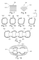
- Fig. 4 schematically shows a perspective view of two coil segments 102, each coil segment 102 comprising two through-holes 701 through which two rods 700 pass, thereby preventing rotation of the two adjacent coil segments 102.
- the through-holes 701 and the rods 702 adapted to pass through the through-holes 701 form a locking means 700 for preventing rotation of the adjacent coil segments 102.
- Fig. 5 schematically shows a perspective view of two coil segments 102, comprising a locking means 700 for preventing rotation of the two adjacent coil segments 102.
- the locking means 700 comprises a latch 801 arranged at each of the plurality coil segments 102 and a recess 802 arranged at each of the two coil segments 102 such that the latch 801 of one coil segment 102 is adapted to fit to the recess of the adjacent coil segment 102.
- the latches 801 are pin-like, and the recesses 802 are hole-like.
- Fig. 6 schematically shows a perspective view of two coil segments 102 having a locking means 700 for preventing rotation of the two adjacent coil segments 102.
- the locking means 700 comprises snap-fit connection 901 arranged at the adjacent coil segments 102, and comprising a clamp 902 and a matching counterpart 903 being arranged at each of the coil segments 102.
- Three clamps 902 and counterparts are arranged at each of the two coil segments.
- Fig. 7 schematically shows a cross-sectional view of a rectangular core 104 of a transformer built from thin sheets 1001 which may be insulated against each other for minimizing the losses from eddy currents.
- Fig. 8 schematically shows a cross-sectional view of a quasi-circular core 104 of a transformer built from thin sheets 1001 which may be insulated against each other for minimizing the losses from eddy currents.
- the steel qualities for the sheets 1001 of Fig. 7 and Fig. 8 may comprise standard core steel, or amorphous core steel.
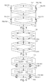
- Fig. 9 schematically shows a cross-sectional view of the windings 1201 of a wound core of a transformer.
- the core may be wound around a mandrel in a first step.
- Fig. 10 schematically shows a cross-sectional view of the windings 1201 of a wound core of a transformer being cut at a certain position indicated by the scissor icon.
- Fig. 11 schematically shows a cross-sectional view of the windings 1201 of a wound core of a transformer being cut and spread/opened in directions indicated by the arrows.
- Fig. 12 schematically shows a cross-sectional view of windings 1201 of a wound core of a transformer wherein moulded high voltage and low voltage coils 601 of a transformer are placed in the windings 1201 of the wound core.
- Fig. 13 schematically shows a cross-sectional view of four windings 1201 of equal wound cores of a transformer being arranged next to each other and combined by three high voltage & low voltage coils 601 forming the transformer.
- Fig. 14 schematically shows a cross-sectional view of windings 1201 of two equally wound small wound cores and one large wound core of a transformer being combined by three high voltage & low voltage coils 601 forming a transformer.
- the core of Fig. 9 to Fig. 14 may comprise one of a non-circular form, such as a rectangular, a hexagonal, or an oval form, and a combination of a circular and a non-circular form.
- Fig. 15 schematically shows a cross-sectional view of three coils 100, 1801 and 1802 of a transformer having a circular cross-section with high voltage coils 401 and low voltage coils 402 being arranged next to each other in the most compact room saving way forming part of a transformer known in the art.
- Fig. 16 schematically shows a cross-sectional view of three coils 100, 1801, 1802 of a transformer having a rectangular cross-section.
- this arrangement is more compact and has a greater mechanical stability as the coils 100, 1801, 1802 are arranged next to each other such that the sides of the rectangular coils 100, 1801, 1802 meet each other in the arrangement providing a shorter distance between the axes of the coils 100, 1801, 1802 compared to the arrangement of Fig. 15 .
- Fig. 17 schematically shows a cross-sectional view of three coils 100, 1801, 1802 of a transformer having a hexagonal form. Compared to the reference arrangement in Fig 15 , this arrangement is more compact and has a greater mechanical stability as the coils 100, 1801, 1802 are arranged next to each other such that the sides of the hexagonal coils 100, 1801, 1802 meet each other in the arrangement providing a shorter distance between the axes of the coils 100, 1801, 1802 compared to the arrangement of Fig. 15 .
- Fig. 18 schematically shows a cross-sectional view of three coils 100, 1801, 1802 of a transformer having an oval form. Compared to the reference arrangement in Fig 15 , this arrangement is more compact and has a greater mechanical stability as the coils 100, 1801, 1802 are arranged next to each other such that the sides of the oval coils 100, 1801, 1802 closest to the axes of the coils 100, 1801, 1802 meet each other in the arrangement providing a shorter distance between the axes of the coils 100, 1801, 1802 compared to the arrangement of Fig. 15 .
- Fig. 19 schematically shows a cross-sectional view of a first coil 100, a second coil 1801, and a third coil 1802 of a transformer.
- Each coil 100, 1801, 1802 may be designed according to Fig. 1 , wherein the coils 100, 1801, 1802 comprise a hexagonal cross-section.
- the coils 100, 1801, 1802 are arranged in a triangular way next to each other such that three sides of the hexagonal coils 100, 1801, 1802 meet each other providing for a greater compactness and mechanical stability of the arrangement compared to a triangular arrangement of coils 100, 1801, 1802 with a circular cross-section according to Fig. 20 because the distances of the axes of the coils 100, 1801, 1802 is shorter compared to the triangular arrangement of Fig. 20 .
- Fig. 20 schematically shows a cross-section of three coils 100, 1801, 1802 having a circular cross-section known in the art.
- the coils 100, 1801, 1802 are arranged in a triangular way next to each other providing for a greater compactness and mechanical stability of the arrangement compared to a linear arrangement of coils 100, 1801, 1802 according to Figs. 15 to 18 because the distances of the axes of the coils 100, 1801, 1802 is shorter compared to the arrangements of Figs. 15 to 18 .
- Fig. 21 schematically shows a cross-sectional view of three coils 100, 1801, 1802 having an oval cross-section.
- Each coil 100, 1801, 1802 may be designed according to Fig. 1 .
- the coils 100, 1801, 1802 are arranged in a triangular way next to each other such that three sides of the oval coils 100, 1801, 1802 closest to the axes of the coils 100, 1801, 1802 meet each other providing for a greater compactness and mechanical stability of the arrangement compared to a triangular arrangement of coils 100, 1801, 1802 with a circular cross-section according to Fig. 20 because the distances of the axes of the coils 100, 1801, 1802 is shorter compared to the triangular arrangement of Fig. 20 .
- Fig. 22 schematically shows a cross-sectional view of three coils 100, 1801, 1802 having a combination of a circular and a non-circular cross-section.
- Each coil 100, 1801, 1802 may be designed according to Fig. 1 .
- the coils 100, 1801, 1802 are arranged in a triangular way next to each other such that three sides of the coils 100, 1801, 1802 closest to the axes of the coils 100, 1801, 1802 meet each other providing for a greater compactness and mechanical stability of the arrangement compared to a triangular arrangement of coils 100, 1801, 1802 with a circular cross-section according to Fig. 20 because the distances of the axes of the coils 100, 1801, 1802 is shorter compared to the triangular arrangement of Fig. 20 .
- Fig. 23 schematically shows a flow-chart of a method 2600 of manufacturing a coil for a transformer with the steps of moulding a supporting device 2601, the moulding comprising the steps of injection-moulding the supporting device by a two-component injection moulding process using a first component comprising a first field control layer and a second component, winding a conductor of a coil module or coil segment around the supporting device of the coil module or coil segment 2602, moulding an insulation material to the conductor and the supporting device 2603, stacking each of the conductors and supporting devices to a coil segment stack or the coil 2604, electrically connecting each coil segment or coil segment of the plurality of coil segments or coil modules to another coil segment or coil module of the plurality of coil segments or coil modules 2605,, and applying a second field control layer of a field control layer arrangement at the edges of the coil segment stack or coil 2606.
- the step of moulding a supporting device 2601 may be omitted.
- the coil may comprise a field control layer arrangement for reducing the maximum field strength of an electric field generated in the coil.
- the supporting devices may comprise a first field control layer.
Abstract
The invention relates to coils of a transformer, and particularly to a transformer having coils arranged to each other. Each coil (100, 1801, 1802) comprising a plurality of coil segments (102) of a modular type, each of which having a uniform cross-section. Each coil segment (102) is electrically connected to another coil segment (102) of the plurality of coil segments (102) forming a stack (100), the stack (100) defining a stack axis (A). The uniform cross-section of each of the plurality of coil segments (102) is a non-circular cross-section. The coils (100, 1801, 1802) of modular coil segments (102) may be efficiently manufactured.

Description
- The invention relates to coils of transformers. In particular, the invention relates to a coil for a transformer and a transformer with the coil.
- In the field of power generation and distribution transformers are widely used.
- The patent application
WO-98/10445 - It may be seen as an object of the invention to provide an improved, flexible and efficient coil for a transformer.
- This object is achieved by a coil for a transformer and by a transformer comprising the coil according to the independent claims. Further embodiments are evident from the dependent claims.
- According to one embodiment of the invention a coil for a transformer is provided comprising a plurality of coil segments of a modular type, each of which having a uniform cross-section. Each coil segment is electrically connected to another coil segment of the plurality of coil segments forming a coil segment stack or the coil, the stack defining a stack axis. The uniform cross-section of each of the plurality of coil segments is a non-circular cross-section and the cross-section is in a plane perpendicular to the stack axis.
- Such a coil may provide for considerable cost-savings, especially, for example, for transformers with low ratings. These cost-savings may be provided mainly from faster production cycles compared to a production of a single non-modular coil or in other words one coil body. The coil as described above may provide a high degree of standardization concerning the manufacturing of the coil enabling variable sizing of the coil and thus time and cost savings compared to a manufacturing of a non-modular coil which is generally designed for manufacturing a defined size of a transformer. The coil with the non-circular cross-section may further enable a reduction of the core steel, as the distance between phases of a transformer may be reduced and thereby less core steel may be used, also if the cores are stacked, for example of cut metal sheets. A coil with coil segments with a uniform non-circular cross-section as described above may enable a faster manufacturing of the core of the transformer. Manufacturing a non-circular core by conventional stacking of cut metal sheets may be more efficient than manufacturing a circular core since all metal sheets may have the same width. Furthermore the transformer with a non-circular cross-section may be built more compact compared to a core with a circular cross-section. The coil may be a modular coil and the transformer may be a dry transformer or a dry distribution transformer. The coil segment may be a modular disk or a disk. The disk or modular disk may comprise a supporting device with a thereto wound conductor, wherein an insulation material may be attached to the supporting device and the conductor for insulating the supporting device and the conductor.
- The electrical connecting of the coil segments to each other may comprise the steps of removing enamel of the connecting means at each coil segment of the plurality of coil segments and crimping the connecting means of each coil segment of the plurality of coil segments to a connecting means of an adjacent coil segment of the plurality of coil segments.
- According to another embodiment of the invention the coil segment comprises at least one high voltage (HV) coil segment.
- According to another embodiment of the invention the coil segment comprises at least one low voltage (LV) coil segment.
- A coil with coil segments of a modular type or in other words a coil of a modular type means that HV and/or LV windings may be adapted as disc windings which may be moulded and which may have two connections or terminals such that the disc windings are stackable.
- High voltage and low voltage coils may be combined in one coil segment according to another embodiment of the invention.
- Furthermore only high voltage coils may be in one coil segment and only low voltage coils may be in one coil segment.
- The high voltage coil may be arranged at a secondary possibly low voltage coil comprising a secondary or low voltage coil conductor in insulating material.
- According to another embodiment of the invention the non-circular cross-section is a cross-section selected from the group consisting of a rectangular, a hexagonal, an oval, and a polygonal cross-section. Such a coil with a non-circular cross-section or an oval cross-section may provide for a compact modular arrangement of the cores of the transformer and the transformer itself.
- According to another embodiment of the invention each of the plurality of coil segments comprises a conductor, a supporting device for supporting the conductor being wound around the supporting device, and an insulation material for insulating the conductor. The insulation material may be moulded around the conductor and the supporting device. The insulation material may be adapted for electromagnetically insulating the coil segment.
- The insulation material may be a thermoplastic material instead of a thermosetting material which may make a curing cycle unnecessary when manufacturing the transformer, thus decreasing the production time of the transformer. Taking into account labour, material costs and depreciation during five years cost-savings of up to 50% may be expected by manufacturing a transformer with the above-mentioned coil compared to manufacturing the transformer with a non-modular coil. Thermoplastic resins with a higher thermo-conductivity would allow using the modular concept of the coil of the transformer also for transformers with high power.
- The modular concept of a coil with coil segments of a modular type may enable the use of a two-compound injection moulding process enabling to have one field grading compound, smoothing the electrical field around the conductor and thereby allowing for the distance between high voltage and low voltage coils of the transformer to be reduced. The supporting device may have a ring form with two sidewalls, in other words the supporting device may be a ring with a U-shaped cross-section. Furthermore the supporting device may have a non-circular form such as one of a rectangular, a non-circular, and a hexagonal form.
- According to another embodiment of the invention a field control layer arrangement for reducing the maximum field strength of an electric field generated in the coil is provided. A first field control layer of the field control layer arrangement is applied at edges of the coil segment.
- The field control layer arrangement may have a high permittivity material with a permittivity of about 10, and the insulation material may have a low permittivity. The field control layer arrangement may be injection-moulded around the conductor. The field control layer arrangement may reduce the maximum field strength of the coil by 50% compared to a coil without a field control layer arrangement and refractive field control may be provided by the field control layer arrangement. The field control layer arrangement may comprise a material selected from the group consisting of a composite material with TiO2, ZnO or BaTiO3 filler. Due to the difference in permittivity between the grading layer and the insulation material, the electric field concentrates in the insulation material and is reduced at the with high permittivity layer coated coil corners or coil edges.
- According to another embodiment of the invention the permittivity ratio of the insulation material to the field control layer arrangement is 1 to 1.5-20, in particular 1 to 2-5 thereby controlling the electric field.
- Such a refractive field control or control of the electric field may be achieved by a specific arrangement of materials with different permittivity; for example materials or devices with a permittivity ratio of 1 to 1.5-20, particularly 1 to 2-5, may be arranged adjacent to each other or over one another thereby enabling the refractive field control or control of the electric field generated in the coil.
- According to another embodiment of the invention a first field control layer of the field control layer arrangement is applied at edges of the coil body.
- The first field control layer may be applied at the inner edges of the coil body facing another coil body, such as a LV coil, for example, and/or at the outer edges of the coil body. The first field control layer may comprise rounded edges and may have the same features as the above mentioned features of the field control layer arrangement.
- According to another embodiment of the invention the coil further comprises at least one second field control layer of the field control layer arrangement.
- According to another embodiment of the invention the supporting device comprises at least one of the at least one second field control layer.
- The at least one second field control layer may be a high epsilon layer. The at least one second field control layer may have the same features as the above mentioned features of the field control layer arrangement.
- According to another embodiment of the invention the coil may further comprise a locking means for preventing rotation of adjacent coil segments of the plurality of coil segments. By locking means a locking system or locking arrangement is meant that may comprise more than one locking devices.
- According to another embodiment of the invention the locking means comprises a through-hole in each of the plurality of coil segments and a rod being adapted to pass through the through-hole of each of the plurality of coil segments.
- The rod may be a threaded rod fitting to threads in the through-holes. Two through-holes may be arranged on opposite sides of the coil segments and two rods may each pass through one of the two through-holes preventing the coil segments from rotating among each other.
- According to another embodiment of the invention the locking means comprises a latch arranged at each of the plurality of coil segments in a recess arranged at each of the plurality of coil segments such that the latch of the coil segments of the plurality of coil segments is adapted to fit to the recess of an adjacent coil segment of the plurality of coil segments.
- Such a latch-recess locking mechanism may prevent the rotation of the coil segments among each other efficiently, wherein each coil segment may be easily stacked to another coil segment. There may be more than one recess and more than one latch arranged at each of the coil segments. Eight latches and eight recesses may be arranged equispaced at each of the coil segments. The recess and the latch may be part of the coil segment and both may have one of a circular, a rectangular, a polygonal, a non-circular, a hexagonal, and a triangular form. Furthermore the latch may be pin-like and the recess may be hole-like.
- According to another embodiment of the invention the locking means comprises a snap-fit connection arranged at adjacent coil segments of the plurality of coil segments. The snap-fit connection may comprise a clamp and a matching counterpart being arranged at each of the plurality of coil segments. There may be a plurality of clamps and counterparts arranged at each of the plurality of coil segments, for example three clamps and three counterparts per coil segment.
- According to another embodiment of the invention the coil further comprises a guiding element for the electrical connection, e.g. in form of a clamp connecting or crimp connecting the plurality of coil segments and for clamp or crimp connecting the coil segments to a further coil of a transformer. The guiding element may be arranged at each of the conductors of the plurality of coil segments.
- According to another embodiment of the invention the conductor is in form of a foil wound around the supporting device enabling a faster manufacturing of the coil compared to a manufacturing of the coil wherein the conductor is in form of a wire wound around the supporting device being a further embodiment of the invention.
- According to another embodiment of the invention the coil body is a high voltage coil body and an insulation material is attached to a low voltage coil. The high voltage coil body is combined with the low voltage coil body surrounding a core of the transformer. The insulation material may be moulded to the low voltage coil.
- According to another embodiment of the invention a transformer is provided having a first coil of anyone of the above-mentioned embodiments, the transformer further comprising a core having a cross-section corresponding to the non-circular cross-section of each of a plurality of coil segments of the first coil. The core may comprise one of a rectangular, a hexagonal, an oval and a non-circular form or combination thereof. The core may generally have a non-circular form.
- According to another embodiment of the invention the core is an amorphous core.
- The core may be built from thin sheets which are insulated against each other for minimizing the losses from eddy currents. Concerning the material of the sheets the following steel qualities for the sheets may be used: Standard core steel (usually low C content of less than 0.1% and alloyed with Si of usually less than 3%); grain oriented core steel, wherein the cold rolling of steel orients the magnetic domains which leads to good loss properties in the rolling direction; amorphous core steel. The core of the transformer may be be stacked or wound, wherein the core may be wound around the mandrel in a first step, cut at one position in a second step, spread/open up for placing the low voltage and high voltage of the transformer in a third step, and the low voltage and high voltage coils may be placed at the core in a fourth step. Four equal wound cores of a transformer may be arranged next to each other being combined by three high voltage and low voltage coils forming the transformer. Two equal wound small cores and one large wound core could be combined by three high voltage and low voltage coils forming a transformer according to a further embodiment.
- According to another embodiment of the invention the transformer further comprises a second coil of anyone of the above-mentioned embodiments and a third coil of anyone of the above-mentioned embodiments, wherein each of the first, second and third coils surrounds the core. The first, second and third coils are arranged in a triangular way next to each other forming a compact transformer.
- Due to the minimal distance of the transformer axes to each other and due to the non-circular cross-sections of the coils in a plane perpendicular to the transformer axes the transformer with triangular arrangement of the coils may provide a greater mechanical stability and a more compact design compared to transformers with coils with a circular cross-section, and also compared to a linear arrangement of the coils. A triangular arrangement of coils with a circular cross-section may provide for a minimized distance of the coil axes to each other and thus a better mechanical stability and space-saving compared to a linear arrangement of coils with a non-circular cross-section.
- According to another embodiment of the invention the transformer further comprises a second coil of anyone of the above-mentioned embodiments and a third coil of anyone of the above-mentioned embodiments, wherein each of the first, second and third coils surrounds the core. The first, second and third coils are arranged in a linear way next to each other forming a compact transformer.
- Such a transformer with a linear arrangement of coils with non-circular cross-sections in a plane perpendicular to the transformer axes or to the core limbs may be built more compact due to a possible more room saving arrangement of the non-circular cross-section coils, for example at edges of the coils, compared to a linear arrangement of coils with circular cross-sections.
- A transformer with a plurality of coils according to anyone of the above mentioned embodiments may be arranged next to each other in the most compact room-saving way depending on the non-circular shape of the cross-section of each of the plurality of coil segments of the plurality of coils such as a triangular way for a hexagonal, and for an oval-cross section or for a cross-section comprising a combination of a non-circular and a circular cross-section. The plurality of coils may be arranged in line, for example three coils next to each other, forming a transformer, wherein each coil segment of the plurality of coil segments of the plurality of coils of the transformer may have one of a rectangular, hexagonal, oval, non-circular, and polygonal form, or a combination of a circular and a non-circular form. Each core may be surrounded by a low voltage coil which is surrounded by a high voltage coil.
- These and other aspects of the present invention will become apparent from and elucidated with reference to the embodiments described hereinafter.
- The subject-matter of the invention will be explained in more detail in the following text with reference to exemplary embodiments which are illustrated in the attached drawings.
-
Fig. 1 schematically shows a cross-sectional view of a coil for a transformer according to an embodiment of the invention. -
Fig. 2 schematically shows a cross-sectional view of a coil segment according to another embodiment of the invention. -
Fig. 3A schematically shows a cross-sectional view of a coil with field control layer arrangements according to another embodiment of the invention. -
Fig. 3B schematically shows a cross-sectional view of one phase of a transformer with a coil according to another embodiment of the invention. -
Fig. 4 schematically shows a perspective view of two coil segments with a locking means comprising holes and rods according to another embodiment of the invention. -
Fig. 5 schematically shows a perspective view of two coil segments with latches and recesses according to another embodiment of the invention. -
Fig. 6 schematically shows a perspective view of two coil segments with snap-fit connections comprising clamps and matching counterparts according to another embodiment of the invention. -
Fig. 7 schematically shows a cross-sectional view of a rectangular core of a transformer according to an embodiment of the invention. -
Fig. 8 schematically shows a cross-sectional view of a circular core of a transformer according to another embodiment of the invention. -
Fig. 9 schematically shows a cross-sectional view of windings of a core of a transformer according to an embodiment of the invention. -
Fig. 10 schematically shows a cross-sectional view of windings of a core of a transformer being cut according to another embodiment of the invention. -
Fig. 11 schematically shows a cross-sectional view of windings of a core of a transformer that have been cut according to another embodiment of the invention. -
Fig. 12 schematically shows a cross-sectional view of high voltage and low voltage coils being placed at windings of a core of a transformer according to another embodiment of the invention. -
Fig. 13 schematically shows a cross-sectional view of four windings of a core of a transformer being connected by high voltage and low voltage coils of the transformer according to another embodiment of the invention. -
Fig. 14 schematically shows a cross-sectional view of three windings of cores of a transformer being connected by high voltage and low voltage coils of the transformer according to another embodiment of the invention. -
Fig. 15 schematically shows a cross-sectional view of three linearly arranged coils of a transformer, the coils having a circular cross-section. -
Fig. 16 schematically shows a cross-sectional view of three linearly arranged coils of a transformer, the coils having a rectangular cross-section according to another embodiment of the invention. -
Fig. 17 schematically shows a cross-sectional view of three linearly arranged coils of a transformer, the coils having a hexagonal cross-section according to another embodiment of the invention. -
Fig. 18 schematically shows a cross-sectional view of three linearly arranged coils of a transformer, the coils having an oval cross-section according to another embodiment of the invention. -
Fig. 19 schematically shows a cross-sectional view of three coils of a transformer, the coils having a hexagonal cross-section being arranged in a triangular way according to an embodiment of the invention. -
Fig. 20 schematically shows a cross-sectional view of three coils of a transformer, the coils having a circular cross-section being arranged in a triangular way. -
Fig. 21 schematically shows a cross-sectional view of three coils of a transformer, the coils having an oval cross-section being arranged in a triangular way according to another embodiment of the invention. -
Fig. 22 schematically shows a cross-sectional view of three coils of a transformer, the coils having a combination of a circular and a non-circular cross-section being arranged in a triangular way according to another embodiment of the invention. -
Fig. 23 schematically shows a flow chart of a method of manufacturing a coil for a transformer according to another embodiment of the invention. - Reference signs used in the drawings, and their meanings, are listed in summary form as a list of reference signs. In principle, identical parts are provided with the same reference signs in the figures.
-
Fig. 1 depicts a cross-sectional view of one phase of a transformer with acoil 100. Thecoil 100 comprises a plurality ofcoil segments 102 of a modular type, each of which having a uniform cross-section. Eachcoil segment 102 is electrically connected to anothercoil segment 102 of the plurality ofcoil segments 102 forming acoil segment stack 100, thestack 100 defining a stack axis A, or in other words thecoil 100. Electrical connections or guidingelements 103 for clamp connecting the plurality ofcoil segments 102 and for clamp connecting thecoil segment stack 100 to a further core of another transformer are provided and may ensure the electrical connection of thecoil segments 102 to each other. A non-circular part of acore 104 of the transformer is surrounded by thecoil 100. The uniform cross section of each of the plurality ofcoil segments 102 is a non-circular cross-section and the cross-section is in a plane perpendicular to the stack axis A. -
Fig. 2 shows a non-circular cross-section of acoil segment 102 ofFig. 1 , the cross-section being in a plane perpendicular to the stack axis A. Thecoil segment 102 comprises aconductor 201 which is supported by supporting device 202, wherein theconductor 201 may be wound around the supporting device 202. Aninsulation material 203 is surrounding theconductor 201 and the supporting device 202 and may be used for an electrical insulation of the conductor. The supporting device 202 has a U-shape in the form of aring 205 with sidewalls. - The supporting device 202 may be moulded by a two compound injection moulding process allowing to have one field grading compound, smoothing the electrical field around the
conductor 201 and thereby allowing for a distance between high voltage and low voltage coils to be reduced and a second compound of a material selected form the group consisting of a thermoset and a thermoplast. - In addition to a first field control layer (not shown, see
Fig. 3A ), the supporting device 202 may comprise a second field control layer 204 for reducing the maximum field strength of the electric field generated in thecoil 100. Theconductor 201 may form a winding 201 wherein a second field control layer may be applied directly atedges 205 of thecoil segment 102. The supporting device 202 may comprise high permittivity thermoplastic. Theinsulation material 203 may be attached or impregnated or moulded to theconductor 201 and the supporting device 202 by first over-moulding or attaching theconductor 201, then over-moulding or attaching the sidewalls of the supporting device 202 in form of a ring 202, and third by over-moulding or attaching an inner wall of the ring 202 with theinsulation material 203. -
Fig. 3A schematically shows acoil 100 with a plurality ofcoil bodies 102, wherein a firstfield control layer 301 is applied atedges 205 of each of the plurality ofcoil segments 102.Insulation material 203 is attached or moulded over each of thecoil segments 102.Fig. 1A depicts a fieldcontrol layer arrangement 200 for reducing the maximum field strength of the electric field generated in thecoil 100. A firstfield control layer 301 of the fieldcontrol layer arrangement 200 is applied atedges 205 of thecoil body 102. One firstfield control layer 301 may be applied atinner edges 205 facing another coil body (not shown), such as a low voltage coil attached or moulded by an insulation material to a low voltage coil body, and an additional firstfield control layer 301 may be applied atouter edges 205 not-facing the adjacent low voltage coil body. The firstfield control layer 301 may also be arranged circumferentially around the conductor (seeFig. 2 ) of the eachcoil segment 102 covering all theedges 205 of thecoil segment 102. At least one second field control layer 204 of the fieldcontrol layer arrangement 200 is provided. The supporting device (seeFig. 2 ) may comprise the at least one second field control layer 204 of the fieldcontrol layer arrangement 200. The fieldcontrol layer arrangement 200 may either comprise the first field control layer 204 or the at least one secondfield control layer 301 or both, the first and the second field control layers 301, 204, and may comprises a plurality of field control layers according to exemplary embodiments of the invention. The permittivity ratio of theinsulation material 203 to the fieldcontrol layer arrangement 200 may be 1 to 1.5-20, in particular 1 to 2-5 thereby controlling the electric field. Refractive field control or control of the electric field may be achieved by a specific arrangement of materials or devices such as the conductor, the supporting device, theinsulation material 203, the fieldcontrol layer arrangement 200, and ambient air with different permittivity; for example materials or devices with a permittivity ratio of 1 to 1.5-20, particularly 1 to 2-5, may be arranged adjacent to each other or over one another thereby enabling the refractive field control or control of the electric field generated in thecoil 100. - The following features and embodiments of descriptions may be applicable to all figures, in particular to
Fig. 1, 2 , and3A . - The transformer may be a dry transformer and cast coils may be used for the dry transformer. The
conductor 201 may be made of a wound foil or wound insulated wire. Mechanical reinforcing structures may be in contact with thecoil segments 102. Theinsulation material 203 close to the edges of thewindings 201 may be submitted to increase electrical stress. To avoid electrical failure of the transformer sufficient insulation distances betweencoil segments 102 and other metallic parts must be kept, especially when the electric strength of the insulation system is reduced due to the presence of interfaces. The main insulation between primary and secondary coil or high voltage and low voltage coils of the dry-type transformer may be air. The transformers may have high voltage, especially a voltage of 10 kV and higher. - The high permittivity of the material may be an intrinsic characteristic of the field control layer material or may be realized by using a filler in a matrix, e.g. high permitted particles in a polymer. If, for example, a first
field control layer 301 with epsilon equal to 10 is used, the maximum field strength at thecoil segment edge 205 is reduced to 50%. An even better result may be achieved, if the first high permittivityfield control layer 301 has rounded corners. - The
insulation material 203 may have a permittivity of 2 to 10. The first and secondfield control layer 301, 204 may have an epsilon 1.5 to 20 times higher than theinsulation material 203. -
Fig. 3B schematically shows a cross-section of one phase of a transformer with a middle axis A (the stack axis according toFig. 1 and Fig. 2 ) separating acore 104 of the transformer. Thecore 104 is coaxially surrounded by alow voltage coil 402 which comprises the low voltage winding 403 and a second insulation material 210 which may be an aluminium sheet attached to the low voltage winding 403 or may be moulded to the low voltage winding 403 having similar characteristics as thefirst insulation material 203. The mouldedlow voltage coil 402 is surrounded by two highvoltage coil segments 102. Each highvoltage coil segment 102 has a supporting device 202 which may comprise a second field control layer 204 supporting theconductor 201 which may be wound around the supporting device 202. Eachconductor 201 and supporting device 202 is moulded or attached by afirst insulation material 203 which may be have the same material as the second insulation material 210. The highvoltage coil segments 102 form a high voltagecoil segment stack 401 which is arranged around the mouldedlow voltage coil 402 surrounding thecore 104 of the transformer 101. - The transformer may be manufactured by moulding or attaching the supporting device 202, winding a
conductor 201 around the supporting device 202, moulding theconductor 201 and the supporting device 202 with afirst insulation material 203, wherein the supporting device 202 and theconductor 201 are inserted into a mould and over-moulded by thefirst insulation material 203 forming a highvoltage coil segment 102. The highvoltage coil segments 102 are stacked to a highvoltage segment stack 401 and the highvoltage coil segments 102 are electrically connected to each other. Thefirst insulation material 203 may comprise a thermoplastic material moulded by injection moulding, or a thermosetting material, processed by vacuum casting or automatic pressure gelation. - The high voltage
coil module stack 401 is then arranged around the mouldedlow voltage coil 402 which is applied or wound around thecore 104 of the transformer. -
Fig. 4 schematically shows a perspective view of twocoil segments 102, eachcoil segment 102 comprising two through-holes 701 through which two rods 700 pass, thereby preventing rotation of the twoadjacent coil segments 102. The through-holes 701 and the rods 702 adapted to pass through the through-holes 701 form a locking means 700 for preventing rotation of theadjacent coil segments 102. -
Fig. 5 schematically shows a perspective view of twocoil segments 102, comprising a locking means 700 for preventing rotation of the twoadjacent coil segments 102. The locking means 700 comprises a latch 801 arranged at each of theplurality coil segments 102 and a recess 802 arranged at each of the twocoil segments 102 such that the latch 801 of onecoil segment 102 is adapted to fit to the recess of theadjacent coil segment 102. The latches 801 are pin-like, and the recesses 802 are hole-like. -
Fig. 6 schematically shows a perspective view of twocoil segments 102 having a locking means 700 for preventing rotation of the twoadjacent coil segments 102. The locking means 700 comprises snap-fit connection 901 arranged at theadjacent coil segments 102, and comprising aclamp 902 and a matchingcounterpart 903 being arranged at each of thecoil segments 102. Three clamps 902 and counterparts are arranged at each of the two coil segments. -
Fig. 7 schematically shows a cross-sectional view of arectangular core 104 of a transformer built fromthin sheets 1001 which may be insulated against each other for minimizing the losses from eddy currents. -
Fig. 8 schematically shows a cross-sectional view of aquasi-circular core 104 of a transformer built fromthin sheets 1001 which may be insulated against each other for minimizing the losses from eddy currents. - The steel qualities for the
sheets 1001 ofFig. 7 and Fig. 8 may comprise standard core steel, or amorphous core steel. -
Fig. 9 schematically shows a cross-sectional view of thewindings 1201 of a wound core of a transformer. The core may be wound around a mandrel in a first step. -
Fig. 10 schematically shows a cross-sectional view of thewindings 1201 of a wound core of a transformer being cut at a certain position indicated by the scissor icon. -
Fig. 11 schematically shows a cross-sectional view of thewindings 1201 of a wound core of a transformer being cut and spread/opened in directions indicated by the arrows. -
Fig. 12 schematically shows a cross-sectional view ofwindings 1201 of a wound core of a transformer wherein moulded high voltage andlow voltage coils 601 of a transformer are placed in thewindings 1201 of the wound core. -
Fig. 13 schematically shows a cross-sectional view of fourwindings 1201 of equal wound cores of a transformer being arranged next to each other and combined by three high voltage &low voltage coils 601 forming the transformer. -
Fig. 14 schematically shows a cross-sectional view ofwindings 1201 of two equally wound small wound cores and one large wound core of a transformer being combined by three high voltage &low voltage coils 601 forming a transformer. - The core of
Fig. 9 to Fig. 14 may comprise one of a non-circular form, such as a rectangular, a hexagonal, or an oval form, and a combination of a circular and a non-circular form. -
Fig. 15 schematically shows a cross-sectional view of threecoils high voltage coils 401 andlow voltage coils 402 being arranged next to each other in the most compact room saving way forming part of a transformer known in the art. -
Fig. 16 schematically shows a cross-sectional view of threecoils Fig 15 , this arrangement is more compact and has a greater mechanical stability as thecoils rectangular coils coils Fig. 15 . -
Fig. 17 schematically shows a cross-sectional view of threecoils Fig 15 , this arrangement is more compact and has a greater mechanical stability as thecoils hexagonal coils coils Fig. 15 . -
Fig. 18 schematically shows a cross-sectional view of threecoils Fig 15 , this arrangement is more compact and has a greater mechanical stability as thecoils oval coils coils coils Fig. 15 . -
Fig. 19 schematically shows a cross-sectional view of afirst coil 100, asecond coil 1801, and athird coil 1802 of a transformer. Eachcoil Fig. 1 , wherein thecoils coils hexagonal coils coils Fig. 20 because the distances of the axes of thecoils Fig. 20 . -
Fig. 20 schematically shows a cross-section of threecoils coils coils Figs. 15 to 18 because the distances of the axes of thecoils Figs. 15 to 18 . -
Fig. 21 schematically shows a cross-sectional view of threecoils coil Fig. 1 . Thecoils oval coils coils coils Fig. 20 because the distances of the axes of thecoils Fig. 20 . -
Fig. 22 schematically shows a cross-sectional view of threecoils coil Fig. 1 . Thecoils coils coils coils Fig. 20 because the distances of the axes of thecoils Fig. 20 . -
Fig. 23 schematically shows a flow-chart of amethod 2600 of manufacturing a coil for a transformer with the steps of moulding a supportingdevice 2601, the moulding comprising the steps of injection-moulding the supporting device by a two-component injection moulding process using a first component comprising a first field control layer and a second component, winding a conductor of a coil module or coil segment around the supporting device of the coil module orcoil segment 2602, moulding an insulation material to the conductor and the supportingdevice 2603, stacking each of the conductors and supporting devices to a coil segment stack or thecoil 2604, electrically connecting each coil segment or coil segment of the plurality of coil segments or coil modules to another coil segment or coil module of the plurality of coil segments orcoil modules 2605,, and applying a second field control layer of a field control layer arrangement at the edges of the coil segment stack orcoil 2606. The step of moulding a supportingdevice 2601 may be omitted. - The coil may comprise a field control layer arrangement for reducing the maximum field strength of an electric field generated in the coil. The supporting devices may comprise a first field control layer.
- While the invention has been illustrated and described in detail in the drawings and the foregoing description, such illustration and description are to be considered illustrative or exemplary and not restricted; the invention is not limited to the disclosed embodiments.
- Other variations of the disclosed embodiments may be understood and effected by those skilled in the art and practising the claimed invention, from a study of the drawings, the disclosure, and the appended claims.
- In the claims, the word "comprising" does not exclude other elements or steps, and the indefinite article "a" or "an" does not exclude a plurality. A single coil or a single transformer may fulfil the function of several items recited in the claims. The mere fact that certain measures are recited in mutually different dependent claims does not indicate that a combination of these measures may not be used to advantage. Any reference signs in the claims should not be construed as limiting the scope.
-
- 100
- Coil, stack of coil segments , first coil
- 102
- coil segment(s), high voltage coil segment(s), modular coil segment(s), coil module(s)
- 103
- Guiding elements, clamps, crimps, electrical connection
- 104
- Core
- 200
- Field control layer arrangement
- 201
- Conductor
- 202
- Supporting device, ring with two sides, ring
- 203
- Insulation material, first insulation material
- 204
- Second field control layer
- 205
- Edges of coil segment(s), edges of supporting device(s)
- 210
- Second insulation material
- 301
- First field control layer
- 401
- High voltage coil segment stack, high voltage coil segment arrangement
- 402
- Moulded low voltage coil(s)
- 403
- Low voltage coil(s), low voltage coil segment
- 601
- High voltage & low voltage coil(s), moulded high voltage coil segment and low voltage coil unit
- 700
- Locking means, locking arrangement
- 701
- Through-hole(s)
- 702
- Rod(s)
- 801
- Latch, latches
- 802
- Recess, recesses
- 901
- Snap-fit connection
- 902
- Clamp(s)
- 903
- Counterpart(s)
- 1001
- Sheet(s), metal sheet(s)
- 1201
-
Windings 1801 Second coil - 1802
- Third coil
Claims (15)
- A coil (100, 1801, 1802) for a transformer, comprising:a plurality of coil segments (102) of a modular type, each of which having a uniform cross-section;wherein each coil segment (102) is electrically connected to another coil segment (102) of the plurality of coil segments (102) forming a stack (100) of coil segments, the stack (100) defining a stack axis (A);wherein the uniform cross-section of each of the plurality of coil segments (102) is a non-circular cross-section and the cross-section is in a plane perpendicular to the stack axis (A).
- The coil (100, 1801, 1802) of claim 1,
wherein the coil segment (102) comprises at least one high voltage (HV) coil segment (102). - The coil (100, 1801, 1802) of claim 1 or 2,
wherein the coil segment (102) comprises at least one low voltage (LV) coil segment (403). - The coil (100, 1801, 1802) of anyone of the preceding claims,
wherein the non-circular cross-section is a cross-section selected from the group consisting of a rectangular, a hexagonal, an oval and a polygonal cross-section. - The coil (100, 1801, 1802) of anyone of the preceding claims,
wherein each of the plurality of coil segments (102) comprises:a conductor (201);a supporting device (202) for supporting the conductor (201) being wound around the supporting device (202),an insulation material (203) for insulating the conductor (201) and the supporting device (202). - The coil (100, 1801, 1802) of anyone of the preceding claims, further comprising:a field control layer arrangement (200) for reducing the maximum field strength of an electric field generated in the coil (100, 1801, 1802);wherein a first field control layer (301) of the field control layer arrangement (200) is applied at edges (205) of the coil segment (102).
- The coil (100, 1801, 1802) of anyone of the preceding claims, further comprising:a locking means (700) for preventing rotation of adjacent coil segments (102) of the plurality of coil segments (102).
- The coil (100, 1801, 1802) of claim 7,
wherein the locking means (700) comprises a through hole (701) in each of the plurality of coil segments (102) and a rod (702) being adapted to pass through the through hole (701) of each of the plurality of coil segments (102). - The coil (100, 1801, 1802) of anyone of claims 7 or 8,
wherein the locking means (700) comprises a latch (801) arranged at each of the plurality of coil segments (102) and a recess (802) arranged at each of the plurality of coil segments (102) such that the latch (801) of a coil segment (102) of the plurality of coil segments (102) is adapted to fit to the recess (802) of an adjacent coil segment (102) of the plurality of coil segments (102). - The coil (100, 1801, 1802) of anyone of claims 7 to 9,
wherein the locking means (700) comprises a snap-fit connection (901) arranged at adjacent coil segments (102) of the plurality of coil segments (102). - The coil (100, 1801, 1802) of anyone of the preceding claims, further comprising:a guiding element (103) for clamp connecting the plurality of coil segments (102) andfor clamp connecting the coil segment stack (100) to a further coil of a transformer.
- The coil (100, 1801, 1802) of anyone of claims 5 to 11,
wherein the conductor (201) is in form of a foil wound around the supporting device (202). - A transformer comprising:a first coil (100) of anyone of claims 1 to 12; anda core (104) having a cross-section corresponding to the non-circular cross-section of each of a plurality of coil segments (102).
- The transformer of claim 13, further comprising:a second coil (1801) of anyone of claims 1 to 12; anda third coil (1802) of anyone of claims 1 to 12;wherein each of the first, second, and third coils (100, 1801, 1802) surrounds a core (104);wherein the first, second, and third coils (100, 1801, 1802) are arranged in a triangular way next to each other forming a compact transformer.
- The transformer of claim 13, further comprising:a second coil (1801) of anyone of claims 1 to 12; anda third coil (1802) of anyone of claims 1 to 12;wherein each of the first, second, and third coils (100, 1801, 1802) surrounds a core (104);wherein the first, second, and third coils (100, 1801, 1802) are arranged in a linear way next to each other forming a compact transformer.
Priority Applications (1)
| Application Number | Priority Date | Filing Date | Title |
|---|---|---|---|
| EP10167489A EP2400511A1 (en) | 2010-06-28 | 2010-06-28 | Modular non-circular coil for transformers |
Applications Claiming Priority (1)
| Application Number | Priority Date | Filing Date | Title |
|---|---|---|---|
| EP10167489A EP2400511A1 (en) | 2010-06-28 | 2010-06-28 | Modular non-circular coil for transformers |
Publications (1)
| Publication Number | Publication Date |
|---|---|
| EP2400511A1 true EP2400511A1 (en) | 2011-12-28 |
Family
ID=42829338
Family Applications (1)
| Application Number | Title | Priority Date | Filing Date |
|---|---|---|---|
| EP10167489A Withdrawn EP2400511A1 (en) | 2010-06-28 | 2010-06-28 | Modular non-circular coil for transformers |
Country Status (1)
| Country | Link |
|---|---|
| EP (1) | EP2400511A1 (en) |
Cited By (1)
| Publication number | Priority date | Publication date | Assignee | Title |
|---|---|---|---|---|
| WO2018208708A1 (en) * | 2017-05-10 | 2018-11-15 | Raytheon Company | High voltage high frequency transformer |
Citations (12)
| Publication number | Priority date | Publication date | Assignee | Title |
|---|---|---|---|---|
| US1411619A (en) * | 1919-12-10 | 1922-04-04 | Gen Electric | Electrical apparatus |
| US3467931A (en) * | 1966-09-23 | 1969-09-16 | Gen Electric | Continuous disk winding and integral radial coil connector for electric transformer and the like |
| US3708875A (en) * | 1971-09-17 | 1973-01-09 | Westinghouse Electric Corp | Methods of constructing electrical inductive apparatus |
| US4344126A (en) * | 1980-10-03 | 1982-08-10 | Ford Motor Company | Low ripple D.C. power supply |
| US4837544A (en) * | 1977-05-13 | 1989-06-06 | Mcdougal John A | Spiral windings |
| WO1998010445A1 (en) | 1996-09-04 | 1998-03-12 | Schneider Electric S.A. | Single coil constitutive of windings for air-core transformers |
| US6269531B1 (en) * | 1998-08-10 | 2001-08-07 | Electro Componentes Mexicana S.A. De C.V. | Method of making high-current coils |
| EP1293995A2 (en) * | 2001-09-14 | 2003-03-19 | STS, Spezial-Transformatoren-Stockach GmbH & Co. | Inductive electronic flat-type component, in particular planar transformer or planar inductor |
| US6806803B2 (en) * | 2002-12-06 | 2004-10-19 | Square D Company | Transformer winding |
| US20060197643A1 (en) * | 2005-03-01 | 2006-09-07 | Darfon Electronics Corp. | Bobbin module of transformer |
| JP2009026951A (en) * | 2007-07-19 | 2009-02-05 | Mitsubishi Electric Corp | Molded coil |
| US20100079229A1 (en) * | 2008-09-26 | 2010-04-01 | Lincoln Global, Inc. | Planar transformer and method of manufacturing |
-
2010
- 2010-06-28 EP EP10167489A patent/EP2400511A1/en not_active Withdrawn
Patent Citations (12)
| Publication number | Priority date | Publication date | Assignee | Title |
|---|---|---|---|---|
| US1411619A (en) * | 1919-12-10 | 1922-04-04 | Gen Electric | Electrical apparatus |
| US3467931A (en) * | 1966-09-23 | 1969-09-16 | Gen Electric | Continuous disk winding and integral radial coil connector for electric transformer and the like |
| US3708875A (en) * | 1971-09-17 | 1973-01-09 | Westinghouse Electric Corp | Methods of constructing electrical inductive apparatus |
| US4837544A (en) * | 1977-05-13 | 1989-06-06 | Mcdougal John A | Spiral windings |
| US4344126A (en) * | 1980-10-03 | 1982-08-10 | Ford Motor Company | Low ripple D.C. power supply |
| WO1998010445A1 (en) | 1996-09-04 | 1998-03-12 | Schneider Electric S.A. | Single coil constitutive of windings for air-core transformers |
| US6269531B1 (en) * | 1998-08-10 | 2001-08-07 | Electro Componentes Mexicana S.A. De C.V. | Method of making high-current coils |
| EP1293995A2 (en) * | 2001-09-14 | 2003-03-19 | STS, Spezial-Transformatoren-Stockach GmbH & Co. | Inductive electronic flat-type component, in particular planar transformer or planar inductor |
| US6806803B2 (en) * | 2002-12-06 | 2004-10-19 | Square D Company | Transformer winding |
| US20060197643A1 (en) * | 2005-03-01 | 2006-09-07 | Darfon Electronics Corp. | Bobbin module of transformer |
| JP2009026951A (en) * | 2007-07-19 | 2009-02-05 | Mitsubishi Electric Corp | Molded coil |
| US20100079229A1 (en) * | 2008-09-26 | 2010-04-01 | Lincoln Global, Inc. | Planar transformer and method of manufacturing |
Cited By (3)
| Publication number | Priority date | Publication date | Assignee | Title |
|---|---|---|---|---|
| WO2018208708A1 (en) * | 2017-05-10 | 2018-11-15 | Raytheon Company | High voltage high frequency transformer |
| US10672553B2 (en) | 2017-05-10 | 2020-06-02 | Raytheon Company | High voltage high frequency transformer |
| US11721477B2 (en) | 2017-05-10 | 2023-08-08 | Raytheon Company | High voltage high frequency transformer |
Similar Documents
| Publication | Publication Date | Title |
|---|---|---|
| CN101512691B (en) | Disc wound transformer and manufacturing method thereof | |
| EP2584574B1 (en) | Reactor | |
| US9197102B2 (en) | Stator assembly for motor having hall sensor part fixed to end of tooth of stator | |
| US20100085139A1 (en) | High Current Amorphous Powder Core Inductor | |
| EP2648317A1 (en) | Stator for rotating electric machine | |
| US8154374B2 (en) | Transformer winding and a method of reinforcing a transformer winding | |
| EP2797090A1 (en) | Thermal management system for SMC inductors | |
| EP2695174B1 (en) | Cable and electromagnetic device comprising the same | |
| WO2012000985A1 (en) | Transformer with field control layer arrangement | |
| US6806803B2 (en) | Transformer winding | |
| KR20150056771A (en) | Optimal inductor | |
| WO2013187501A1 (en) | Coiled member and coil device | |
| CN208127003U (en) | three-phase reactor | |
| CN107077953A (en) | Coil form with low interwinding capacity | |
| EP2400511A1 (en) | Modular non-circular coil for transformers | |
| WO2012000984A1 (en) | Coil for transformers made from coil segments with locking means | |
| EP2400510A1 (en) | Transformer coil with conductive electrical shielding | |
| US8487732B2 (en) | Coil transformer composed of unit configuration | |
| JP2005158857A (en) | Mold coil | |
| WO1999028919A1 (en) | Magnetic core assemblies | |
| JP2016039322A (en) | Coil and coil component | |
| CN112216481A (en) | Magnetic induction coil | |
| EP2479764B1 (en) | Resin molded coil and molded transformer using the same | |
| CN210325464U (en) | Magnetic induction coil | |
| JP2009178002A (en) | Bobbin, rotary electric machine, and method of manufacturing bobbin |
Legal Events
| Date | Code | Title | Description |
|---|---|---|---|
| AK | Designated contracting states |
Kind code of ref document: A1 Designated state(s): AL AT BE BG CH CY CZ DE DK EE ES FI FR GB GR HR HU IE IS IT LI LT LU LV MC MK MT NL NO PL PT RO SE SI SK SM TR |
|
| AX | Request for extension of the european patent |
Extension state: BA ME RS |
|
| PUAI | Public reference made under article 153(3) epc to a published international application that has entered the european phase |
Free format text: ORIGINAL CODE: 0009012 |
|
| STAA | Information on the status of an ep patent application or granted ep patent |
Free format text: STATUS: THE APPLICATION IS DEEMED TO BE WITHDRAWN |
|
| 18D | Application deemed to be withdrawn |
Effective date: 20120629 |