EP2400322A1 - Image display body and image formation method - Google Patents
Image display body and image formation method Download PDFInfo
- Publication number
- EP2400322A1 EP2400322A1 EP11182061A EP11182061A EP2400322A1 EP 2400322 A1 EP2400322 A1 EP 2400322A1 EP 11182061 A EP11182061 A EP 11182061A EP 11182061 A EP11182061 A EP 11182061A EP 2400322 A1 EP2400322 A1 EP 2400322A1
- Authority
- EP
- European Patent Office
- Prior art keywords
- colored
- diffraction structure
- optical diffraction
- hologram
- image display
- Prior art date
- Legal status (The legal status is an assumption and is not a legal conclusion. Google has not performed a legal analysis and makes no representation as to the accuracy of the status listed.)
- Withdrawn
Links
- 238000000034 method Methods 0.000 title claims description 45
- 230000015572 biosynthetic process Effects 0.000 title claims description 5
- 230000003287 optical effect Effects 0.000 claims abstract description 81
- 239000000463 material Substances 0.000 claims abstract description 38
- 238000009792 diffusion process Methods 0.000 claims abstract description 22
- 238000012546 transfer Methods 0.000 claims description 68
- 230000000694 effects Effects 0.000 abstract description 14
- 239000010410 layer Substances 0.000 description 71
- 239000002184 metal Substances 0.000 description 13
- 229910052751 metal Inorganic materials 0.000 description 13
- 239000003086 colorant Substances 0.000 description 6
- 239000010931 gold Substances 0.000 description 4
- 229910052737 gold Inorganic materials 0.000 description 4
- 239000010409 thin film Substances 0.000 description 4
- 239000000956 alloy Substances 0.000 description 3
- 238000004040 coloring Methods 0.000 description 3
- 238000013461 design Methods 0.000 description 3
- 230000002195 synergetic effect Effects 0.000 description 3
- UCKMPCXJQFINFW-UHFFFAOYSA-N Sulphide Chemical compound [S-2] UCKMPCXJQFINFW-UHFFFAOYSA-N 0.000 description 2
- 229910045601 alloy Inorganic materials 0.000 description 2
- 229910052782 aluminium Inorganic materials 0.000 description 2
- 229910052804 chromium Inorganic materials 0.000 description 2
- 230000001276 controlling effect Effects 0.000 description 2
- 238000007796 conventional method Methods 0.000 description 2
- 230000008021 deposition Effects 0.000 description 2
- 239000011888 foil Substances 0.000 description 2
- PCHJSUWPFVWCPO-UHFFFAOYSA-N gold Chemical compound [Au] PCHJSUWPFVWCPO-UHFFFAOYSA-N 0.000 description 2
- 229910052759 nickel Inorganic materials 0.000 description 2
- 150000004767 nitrides Chemical class 0.000 description 2
- 229910052709 silver Inorganic materials 0.000 description 2
- 230000000007 visual effect Effects 0.000 description 2
- 241000579895 Chlorostilbon Species 0.000 description 1
- 150000001875 compounds Chemical class 0.000 description 1
- 238000011109 contamination Methods 0.000 description 1
- 230000002596 correlated effect Effects 0.000 description 1
- 230000000875 corresponding effect Effects 0.000 description 1
- 238000005034 decoration Methods 0.000 description 1
- 238000010586 diagram Methods 0.000 description 1
- 229910052876 emerald Inorganic materials 0.000 description 1
- 239000010976 emerald Substances 0.000 description 1
- 239000000314 lubricant Substances 0.000 description 1
- 238000012986 modification Methods 0.000 description 1
- 230000004048 modification Effects 0.000 description 1
- 239000011241 protective layer Substances 0.000 description 1
- 239000010979 ruby Substances 0.000 description 1
- 229910001750 ruby Inorganic materials 0.000 description 1
- 229910052594 sapphire Inorganic materials 0.000 description 1
- 239000010980 sapphire Substances 0.000 description 1
- 230000008022 sublimation Effects 0.000 description 1
- 238000000859 sublimation Methods 0.000 description 1
- 238000005092 sublimation method Methods 0.000 description 1
- 239000000126 substance Substances 0.000 description 1
Images







Classifications
-
- G—PHYSICS
- G02—OPTICS
- G02B—OPTICAL ELEMENTS, SYSTEMS OR APPARATUS
- G02B5/00—Optical elements other than lenses
- G02B5/18—Diffraction gratings
- G02B5/1842—Gratings for image generation
-
- G—PHYSICS
- G03—PHOTOGRAPHY; CINEMATOGRAPHY; ANALOGOUS TECHNIQUES USING WAVES OTHER THAN OPTICAL WAVES; ELECTROGRAPHY; HOLOGRAPHY
- G03H—HOLOGRAPHIC PROCESSES OR APPARATUS
- G03H1/00—Holographic processes or apparatus using light, infrared or ultraviolet waves for obtaining holograms or for obtaining an image from them; Details peculiar thereto
- G03H1/04—Processes or apparatus for producing holograms
- G03H1/18—Particular processing of hologram record carriers, e.g. for obtaining blazed holograms
-
- B—PERFORMING OPERATIONS; TRANSPORTING
- B44—DECORATIVE ARTS
- B44C—PRODUCING DECORATIVE EFFECTS; MOSAICS; TARSIA WORK; PAPERHANGING
- B44C1/00—Processes, not specifically provided for elsewhere, for producing decorative surface effects
- B44C1/16—Processes, not specifically provided for elsewhere, for producing decorative surface effects for applying transfer pictures or the like
- B44C1/165—Processes, not specifically provided for elsewhere, for producing decorative surface effects for applying transfer pictures or the like for decalcomanias; sheet material therefor
- B44C1/17—Dry transfer
- B44C1/1704—Decalcomanias provided with a particular decorative layer, e.g. specially adapted to allow the formation of a metallic or dyestuff layer on a substrate unsuitable for direct deposition
-
- B—PERFORMING OPERATIONS; TRANSPORTING
- B44—DECORATIVE ARTS
- B44F—SPECIAL DESIGNS OR PICTURES
- B44F1/00—Designs or pictures characterised by special or unusual light effects
- B44F1/08—Designs or pictures characterised by special or unusual light effects characterised by colour effects
-
- G—PHYSICS
- G02—OPTICS
- G02B—OPTICAL ELEMENTS, SYSTEMS OR APPARATUS
- G02B5/00—Optical elements other than lenses
- G02B5/18—Diffraction gratings
Definitions
- the present invention relates to an image display body in which an optical diffraction structure is formed in a halftone dot state and an image information method for the image display body.
- a transfer foil having an optical diffraction structure forming layer is utilized for the purposes of improving design performance and security performance.
- the optical diffraction structure having a fine concavo-convex relief structure such as a hologram and a diffraction grating is formed in the optical diffraction structure forming layer.
- JP09-160475 and JP08-328456 describe a colored layer transfer material having a fine relief structure and a reflecting layer made of a metal colored a unique color to obtain an effect of looking like a colored optical diffraction structure (hereinafter sometimes referred to as "colored hologram").
- JP61-238079 and JP62-17784 disclose a layer configuration, in which the optical diffraction structure forming layer and the reflecting layer are laminated and a colored layer is added to an observation side to the reflecting layer in order to obtain the effect of looking like the colored hologram
- JP63-30288 , JP63-230389 and JP09-11638 describe a colored layer transfer material having the colored layer and the metal layer (the reflecting layer) looking like, for example, gold.
- the colored layer transfer material can be transferred onto a transfer body to obtain a colored-metal glossy color.
- the fine concavo-convex relief structure such as a hologram and a diffraction grating which exerts the optical diffraction effect is not provided, the particular design or the optical effect cannot be obtained.
- JP08-123299 , JP11-227368 and JP2004-101834 describe methods of forming an optical diffraction structure portion having optical diffraction structure in a halftone dot state to add a decorative effect by diffracted light to an image, by transferring the optical diffraction structure in a halftone dot state onto a base material having a predetermined image.
- the colored layer transfer material has a single color, and it is impossible to color the optical diffraction structure plural desired colors. For example, it is difficult to color plural portions of the optical diffraction structure different colors such as gold, a sapphire tone, an emerald tone, and a ruby tone. Accordingly, there is no colored layer transfer material having a low cost, good productivity, good storage stability of a color tone, and the optical diffraction effect by the optical diffraction structure.
- the present invention seeks to provide an image display body in which the optical diffraction structure appears to be colored a desired color and where the decoration effect is obtained more effectively.
- an image display body in which an optical diffraction structure portion constituted by an optical diffraction structure in a halftone dot state is provided in a colored region on a base material, wherein the percentage of the dot area of the halftone dots, constituting the optical diffraction structure portion, to the colored region ranges from 15% to 60%, the area of each halftone dot is smaller than 0.25 mm 2 , and the halftone dots are diffused to be provided by an error diffusion method.
- the inventor has discovered that natural brightness based on diffracted light can be given evenly to the colored region by providing the halftone dots on the colored region, where the halftone dots are diffused by an error diffusion method and have the percentages defined.
- the brightness can be given evenly to the colored region
- the colored region where the optical diffraction structure portion is formed can be used such as a colored optical diffraction structure.
- the optical diffraction structure includes a diffraction grating having a constant concavo-convex pattern and a hologram where a fringe pattern generating a predetermined hologram image is formed. It doesn't matter which error diffusion method is employed such as a random dithering method, Floyd&Steinberg type, and Judice&Ninke type. Also, it doesn't matter which printing method is taken for the colored region. Moreover, the colored region may be colored a single color. Thereby, the colored region where the optical diffraction structure is formed can be used as a single-colored optical diffraction structure colored the color of the colored region.
- the present invention also extends to an image formation method in which an optical diffraction structure forming layer is transferred in a halftone dot state to a colored region on a transfer body to form an optical diffraction structure portion by using a transfer sheet where the optical diffraction structure forming layer in which an optical diffraction structure is formed is laminated on a base material sheet thereof, wherein the halftone dots constituting the optical diffraction structure portion are transferred to the colored region in a diffused state by an error diffusion method so that the area of the halftone dot is smaller than 0.25 mm 2 and the percentage of the dot area to the colored region ranges from 15% to 60%.
- the first image display body can be obtained.
- the optical diffraction structure forming layer may be thermally transferred from the transfer sheet to the colored region by using a thermal head, and each of the halftone dots may be transferred based on printing energy applied to the thermal head so that the halftone dots are diffused in a state of the area and the dot area percent by the error diffusion method.
- the printing energy of the thermal head can be optimized based on materials of the optical diffraction structure and the transfer body. As each halftone dot is transferred based on the optimized printing energy, the image display body having more natural brightness can be obtained.
- the colored region of the transfer body may be colored a single color.
- the colored region where the optical diffraction structure is formed can be used as a single-colored optical diffraction structure colored the color of the colored region.
- the diffraction structure in a halftone dot state is provided to the colored region under the conditions that the area of each halftone dot is smaller than 0.25 mm 2 , the dot area percent ranges from 15% to 60%, and the halftone dots are diffused by the error diffusion method.
- the image display body and the like in which the optical diffraction structure appeared to be colored the desired color, and the decorative effect is obtained more effectively can be provided.
- the mode where halftone dots are arranged on an image in a size and a distance the image display body where more decorative effect by an optical diffraction structure is given to the image can be provided
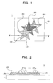
- Fig. 1 shows an example of an image display body 1 of the present invention.
- the image display body 1 includes plural colored portions 20, 30, and 40 on a base material 10.
- the colored portions 20, 30, and 40 are colored the different colors respectively.
- an optical diffraction structure in a halftone dot state is provided as an optical diffraction structure portion 21. Therefore, a visual effect by diffracted light is given to the colored portion 20 in addition to the coloring.
- the colored portion 20 in the state in which the optical diffraction structure portion 21 is provided is referred to as colored hologram portion 22.
- the colored portions 20, 30, and 40 are colored by a dye sublimation printing in the present embodiment, any printing method may be employed to color the colored portions 20, 30, and 40.
- a diffraction grating is used as the optical diffraction structure constituting the optical diffraction structure portion 21.
- the optical diffraction structure includes the diffraction grating and a hologram, and the diffraction grating constituted by a constant concavo-convex pattern is strictly distinguished from the hologram constituted by a fringe pattern generating a predetermined hologram image.
- the hologram is used in the same meaning of the optical diffraction structure. Materials respectively used for the base material 10 and colored portion 20 may be appropriately determined according to a use purpose of the image display body 1.
- hologram Any type of hologram may be used in the optical diffraction structure portion 21 as long as a hologram is a diffraction grating which can be formed as a hologram forming layer onto a later-mentioned hologram transfer sheet.
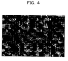
- the colored portion 20 constituted with ink is laminated on the base material 10 in the colored hologram portion 22 of the image display body 1, and plural halftone dots 21 a, ..., 21 a constituting the optical diffraction structure portion 21 are provided all over the colored portion 20.
- An area of each halftone dot 21 a is smaller than 0.25 mm 2 , and a halftone dot area percent to the colored hologram portion 22 ranges from 15% to 60%.
- the halftone dots 21 a are provided while diffused by an error diffusion method, namely, the halftone dots 21 a are provided not in a state where the halftone dots having a constant shape are regularly arranged at equal intervals, but in a state where the uneven halftone dots are unevenly disposed.
- the plural halftone dots 21 a, ... , 21 a constituting the optical diffraction structure portion 21 are provided in the colored portion 20 under the above conditions, whereby natural brightness by the diffracted light is represented in all over the colored hologram portion 22, and the colored hologram portion 22 looks like a hologram colored the color of the colored portion 20.
- the colored hologram portion 22 looks like the hologram colored red.
- Figs. 3 to 5 show the states in which the plural halftone dots 21 a are provided in the colored portion 20 with dot area percents of 15%, 35%, and 60% respectively. In each drawing, a whitish portion is a portion where the halftone dot 21 a is provided.
- the image display body 1 is produced with an image producing apparatus 50 as shown in Fig. 6 .
- the image producing apparatus 50 includes an input unit 51, a display unit 52, a hologram transfer unit 53, a storage unit 54, a body where to be transferred supply unit 55, a discharge unit 56, and a control unit 57.
- the input unit 51 accepts various kinds of setting operations of a user.
- the display unit 52 displays an image corresponding to the setting by the user or various messages to the user.
- the hologram transfer unit 53 transfers the hologram.
- Various kinds of drawing patterns and various kinds of information to be provided on the base material 10 are stored in the storage unit 54.
- the transfer body supply unit 55 supplies a transfer body.
- the discharge unit 56 discharges the produced image display body 1.
- the control unit 57 controls operations of the units 51, ..., 56.
- the hologram transfer unit 53 prints the hologram by using a hologram transfer sheet 60 shown in Fig. 7 by a thermal transfer method.
- a peel layer 62, a hologram forming layer 63 in which the hologram is formed, a reflecting layer 64, and a bonding layer 65 are laminated on one side of a base material sheet 61, while a heat-resistant layer 66 is provided on the other side of the base material sheet 61.
- the hologram transfer sheet 60 of the present embodiment is a transfer foil in which the diffraction grating is formed as the hologram of the hologram forming layer 63.
- the bonding layer 65 is bonded to the transfer body, and a thermal head is pressed against the hologram transfer sheet 60 from the side of the heat-resistant layer 66, which peels off the side of the base material sheet 61 from the side of the hologram forming layer 63 to transfer the hologram forming layer 63 onto the transfer body.
- Each of the layers 61, ... , 66 may be made of well-known materials.
- An aspect in which the hologram forming layer 63 is transferred onto the transfer body includes an aspect in which the hologram transfer sheet 60 is peeled off between the base material sheet 61 and the peel layer 62 to transfer the layers 62 to 65 including the hologram forming layer 63 onto the transfer body, an aspect in which the hologram transfer sheet 60 is peeled off between the peel layer 62 and the hologram forming layer 63 to transfer the layers 63 to 65 including the hologram forming layer 63 onto the transfer body, and an aspect in which the hologram transfer sheet 60 is peeled off at the peel layer 62 into the side of the hologram forming layer 63 and the side of the base material sheet 61 to transfer the hologram forming layer 63 onto the transfer body.
- a relief diffraction effect can be enhanced by providing the reflecting layer 64 to a relief surface of the hologram forming layer 63.
- the reflecting layer 64 is made of a metal having a high light reflectance. The higher light reflectance of the metal constituting the reflecting layer 64 is, the brighter diffracted light is obtained.
- the reflecting layer 64 may be formed by a single thin film made of a metal such as Cr, Ni, Ag, Au, and Al, an oxide, a sulfide, and a nitride thereof, and a combination thereof.
- the metal thin film having the high light reflectance has a thickness ranging from around 10 to 2000 nm, preferably from 20 to 1000 nm so as to obtain a sufficient reflecting effect.
- An image display body 1' as shown in Fig. 8 may be used as the transfer body.
- the plural colored portions 20, 30, and 40 are provided on the base material 10.
- the coloring of the colored portions 20, 30, and 40 is printed by the dye sublimation method, the colored portions 20, 30, and 40 may be colored by other printing methods.
- the transfer body supply unit 55 plural variations colored different colors are prepared as the colored portions 20, 30, and 40.
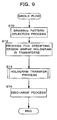
- Step S70 a drawing pattern selection process is performed (Step S70).
- the process lets the user select his/her desiring colored drawing-pattern to be provided on the base material 10.
- the plural selectable colored drawing-patterns are displayed on the display unit 52, and the input unit 51 accepts the user selection operation.
- the image display body 1' is displayed on the display unit 52 according to the user selection operation during the drawing pattern selection process. At this point, sizes and positions of the colored portions 20, 30, and 40 may be appropriately changed by the input operation of the user.
- the process lets the user specify a region where the hologram is transferred in the image display body 1' (Step S72).
- the process lets the user select the drawing pattern onto which the hologram is transferred in the image display body 1'.
- the case in which the colored portion 20 of the image display body 1' is selected will be described below.
- a hologram transfer process is performed (Step S74).
- the optical diffraction structure portion 21 is formed in the colored portion 20 to produce the image display body 1.
- the specific process of the hologram transfer process is described later.
- the produced image display body 1 is discharged from the discharge unit 56 (Step S76), and the processes concerning producing of the image display body 1 finishes.
- the hologram transfer process will be specifically described with reference to a flowchart shown in Fig. 10 .
- gray-scale information is read from the storage unit 54 (Step S80).
- the gray-scale information means a proportion of an area which the hologram occupies to a predetermined region, e.g. one dot, when the hologram is transferred.
- the gray-scale information is set as a value of printing energy given to the thermal head.
- the optimum value of the gray-scale information is previously set according to the material constituting the hologram of the hologram forming layer 63 and the image display body 1', and the use application of the image display body 1.
- the optimum value of the gray-scale information is stored in the storage unit 54.
- a diffusion process is performed based on the gray-scale information (Step S82).
- the information on the halftone dot 21 a determined in the diffusion process is referred to as halftone dot information.
- the predetermined conditions mean the area of the halftone dot, the dot area percent to the colored portion 20, and the process performed by the error diffusion method.
- the halftone dot information on each halftone dot 21 a is computed such that the halftone dot 21 a has the area of 0.04 mm 2 , the dot area percent is 30%, and the halftone dots 21 a are arranged in a state of being diffused by a random dithering method which is one of the error diffusion methods.
- the area of the halftone dot 21 a may be smaller than 0.25mm 2 , and the dot area percent may range from 15% to 60%.
- the error diffusion method is not limited to the random dithering method, but any method may be employed. Appropriate values of the area and dot area percent are previously set according to the use purpose of the image display body 1.
- the gray-scale information is the proportion of the area which the hologram can occupy to the predetermined region.
- a white region 90 where to transfer the hologram occupies 35% of the whole of the colored portion 20 and a black region 91 where not to transfer the hologram occupies the other 65%.
- a post-diffusion process state B of Fig. 11 shows a state where the diffusion is performed at the dot area percent of 35% in the colored portion 20 which is a rectangular shape.
- the thermal head operation is controlled based on the halftone dot information, and the hologram forming layer 63 is thermally transferred from the hologram transfer sheet 60 onto the colored portion 20 in the halftone dot state in the above-described manner (Step S84).
- the optical diffraction structure portion 21 can be provided on the colored portion 20.
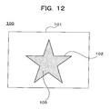
- Fig. 12 is a view showing an example of an image display body 100 which may not be an embodiment of the present invention.
- an optical diffraction structure portion 103 constituted by optical diffraction structure is formed in a halftone dot state on an image 102 provided to a predetermined base material 101.
- each of plural halftone dots 110, ... , 110 constituting the optical diffraction structure portion 103 can be enclosed by each of square regions 111, ... , 111 whose sizes are equal to one another, and the plural square regions 111, ... , 111 are formed so as to be arranged at equal intervals in diagonal directions 112, ... , 112.
- a length of one side of the square region 111 may be 400 ⁇ m or less, and preferably the length ranges from 100 to 200 ⁇ m.
- all distances d between a corner 11 a of one of the square region 11 and a corner 11 b of the other square region 11 are equal to one another and should be 220 ⁇ m or less.
- the distance d ranges from 50 to 150 ⁇ m.
- the dot area percent of the halftone dots 110, ... , 110 to the area of the image 102 is 40% or less.
- the material for the base material 101 and the method of forming the image 102 may be appropriately determined according to the use application of the image display body 100.
- Examples of the image display body 100 include cards such as a credit card, an ID card, and a prepaid card and paper tickets such as an exchange coupon, a check, paper money, a stock certificate, an entrance ticket, and various certificates. Any card or paper ticket can be used as the image display body 100 as long as the card or paper ticket has the image 102 on the base material 101.
- the image 102 also includes a substance formed by various kinds of printing methods and a photograph.
- a method of forming the optical diffraction structure portion 103 in the image 102 by using a transfer sheet 120 shown in Fig. 14 will be described.
- a peel layer 122, an optical diffraction structure layer 123, a reflecting layer 124, and a bonding layer 125 are laminated on a base material sheet 121, and a heat-resistant protective layer 126 is formed on the backside of the base material sheet 121.
- the concavo-convex pattern of the diffraction grating is formed as the optical diffraction structure.
- the relief diffraction effect can be enhanced by providing the reflecting layer 124 on the relief surface of the optical diffraction structure layer 123.
- the reflecting layer 124 is made of a metal having the high light reflectance.
- the higher light reflectance of the metal constituting the reflecting layer 124 is, the brighter diffracted light is obtained.
- the reflecting layer 124 may be formed by a single thin film made of a metal such as Cr, Ni, Ag, Au, and Al, an oxide, a sulfide, or a nitride thereof, or a combination thereof.
- the metal thin film having the high light reflectance has a thickness ranging from around 10 to 2000 nm, preferably from 20 to 1000 nm so as to obtain the sufficient reflecting effect.
- the thermal transfer printer transfers the optical diffraction structure layer 123 of the transfer sheet 120 to a transfer body 130 in which the image 102 is provided to the base material 101 as shown in Fig. 15A .
- the thermal transfer printer By controlling the thermal head operation of the thermal transfer printer, the halftone dots 110, ... , 110 can be formed on the image 102 in the above mentioned sate by the optical diffraction structure layer 123.
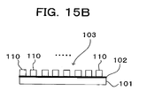
- Fig. 15B is a view showing the state in which the optical diffraction structure portion 103 is formed by transferring the optical diffraction structure layer 123 as the halftone dots 110, ... , 110 onto the image 102 provided to the base material 101.
- the optical diffraction structure portion 103 is formed on the image 102, and a natural lame effect can be given to the image 102 by the diffracted light.
- An image display body 1 of the present invention is not limited to the described embodiment, and can be realized in various embodiments. At least one colored portion of the image display body 1 may be required, and the whole of the image display body 1 may be colored. The colors of the plural colored portions may be different from one another or identical to one another.
- the shape of the colored portion 20 of the image display body 1 is not limited to the star shape.
- plural kinds of transferable holograms may be prepared and the user may be allowed to select the desired hologram.
- the optimum gray-scale information may be previously set to each hologram and correlated with the hologram.
- the region to which the hologram is transferred may be previously determined.
- a printing unit which colors the base material 10 may be provided in the image producing apparatus 50.
- the peel layer 62 and the bonding layer 65 when the other layers have the sufficient peel properties or bonding properties.
- Other layers such as a surface lubricant layer may be provided if needed.
Landscapes
- Physics & Mathematics (AREA)
- General Physics & Mathematics (AREA)
- Optics & Photonics (AREA)
- Credit Cards Or The Like (AREA)
- Holo Graphy (AREA)
- Diffracting Gratings Or Hologram Optical Elements (AREA)
Abstract
An image display body (1) has an optical diffraction structure portion (21) which is provided in a colored region 20 on a base material 10 in a halftone dot state. In the image display body (1), the percentage of the dot area of a halftone dot (21 a) constituting the optical diffraction structure portion (21) to the colored region 20 ranges from 15% to 60%. The area of each halftone dot (21 a) is smaller than 0.25 mm2. The halftone dots (21 a) are diffused by an error diffusion method. As a result, the image display body (1) has a decorative effect which has been obtained more effectively.
Description
- The present invention relates to an image display body in which an optical diffraction structure is formed in a halftone dot state and an image information method for the image display body.
- A transfer foil having an optical diffraction structure forming layer is utilized for the purposes of improving design performance and security performance. The optical diffraction structure having a fine concavo-convex relief structure such as a hologram and a diffraction grating is formed in the optical diffraction structure forming layer. There is a known method of coloring the optical diffraction structure in order to improve the design performance and the security performance. For example,
JP09-160475 JP08-328456 -
JP61-238079 JP62-17784 -
JP63-30288 JP63-230389 JP09-11638 -
JP08-123299 JP11-227368 JP2004-101834 - However, in the method of configuring the reflecting layer by using the metal colored the unique color, due to the use of an alloy having its unique color, it is very difficult that continuous deposition is performed while a desired compound ratio of the alloy is stably kept. It takes a lot of time to provide an exchange a predetermined alloy material during the deposition, that could cause a risk of contamination (pollution with the material used before and after) is generated, and thereby the method of forming the reflecting layer with the metal colored the intrinsic color has a cost disadvantage.
- In the method of adding and providing the colored layer, basically the colored layer transfer material has a single color, and it is impossible to color the optical diffraction structure plural desired colors. For example, it is difficult to color plural portions of the optical diffraction structure different colors such as gold, a sapphire tone, an emerald tone, and a ruby tone. Accordingly, there is no colored layer transfer material having a low cost, good productivity, good storage stability of a color tone, and the optical diffraction effect by the optical diffraction structure.
- Additionally, in the conventional method of transferring the optical diffraction structure in the halftone dot state, a visual synergic effect obtained by the diffracted light of the optical diffraction structure portion and the color of a region located below the optical diffraction structure portion is hardly considered. Accordingly, it sometimes happens that almost of the colored region is covered with the transferred optical diffraction structure.
- Even if the case where the above synergic effect is considered, in the conventional transfer method, brightness by the diffracted light of the optical diffraction structure portion frequently becomes unnatural, and the synergic effect is not sufficiently exerted.
- The present invention seeks to provide an image display body in which the optical diffraction structure appears to be colored a desired color and where the decoration effect is obtained more effectively.
- According to a first aspect of the present invention there is provided an image display body in which an optical diffraction structure portion constituted by an optical diffraction structure in a halftone dot state is provided in a colored region on a base material, wherein the percentage of the dot area of the halftone dots, constituting the optical diffraction structure portion, to the colored region ranges from 15% to 60%, the area of each halftone dot is smaller than 0.25 mm2, and the halftone dots are diffused to be provided by an error diffusion method.
- The inventor has discovered that natural brightness based on diffracted light can be given evenly to the colored region by providing the halftone dots on the colored region, where the halftone dots are diffused by an error diffusion method and have the percentages defined. As the brightness can be given evenly to the colored region, the colored region where the optical diffraction structure portion is formed can be used such as a colored optical diffraction structure.
- In an embodiment, the optical diffraction structure includes a diffraction grating having a constant concavo-convex pattern and a hologram where a fringe pattern generating a predetermined hologram image is formed. It doesn't matter which error diffusion method is employed such as a random dithering method, Floyd&Steinberg type, and Judice&Ninke type. Also, it doesn't matter which printing method is taken for the colored region. Moreover, the colored region may be colored a single color. Thereby, the colored region where the optical diffraction structure is formed can be used as a single-colored optical diffraction structure colored the color of the colored region.
- The present invention also extends to an image formation method in which an optical diffraction structure forming layer is transferred in a halftone dot state to a colored region on a transfer body to form an optical diffraction structure portion by using a transfer sheet where the optical diffraction structure forming layer in which an optical diffraction structure is formed is laminated on a base material sheet thereof, wherein the halftone dots constituting the optical diffraction structure portion are transferred to the colored region in a diffused state by an error diffusion method so that the area of the halftone dot is smaller than 0.25 mm2 and the percentage of the dot area to the colored region ranges from 15% to 60%.
- With embodiments of a method of the invention, the first image display body can be obtained.
- The optical diffraction structure forming layer may be thermally transferred from the transfer sheet to the colored region by using a thermal head, and each of the halftone dots may be transferred based on printing energy applied to the thermal head so that the halftone dots are diffused in a state of the area and the dot area percent by the error diffusion method. Thereby, the printing energy of the thermal head can be optimized based on materials of the optical diffraction structure and the transfer body. As each halftone dot is transferred based on the optimized printing energy, the image display body having more natural brightness can be obtained.
- The colored region of the transfer body may be colored a single color. Thereby, the colored region where the optical diffraction structure is formed can be used as a single-colored optical diffraction structure colored the color of the colored region.
- As set out above, the diffraction structure in a halftone dot state is provided to the colored region under the conditions that the area of each halftone dot is smaller than 0.25 mm2, the dot area percent ranges from 15% to 60%, and the halftone dots are diffused by the error diffusion method. By these means, the image display body and the like in which the optical diffraction structure appeared to be colored the desired color, and the decorative effect is obtained more effectively can be provided. Moreover, by specifying the mode where halftone dots are arranged on an image in a size and a distance, the image display body where more decorative effect by an optical diffraction structure is given to the image can be provided
- Embodiments of the present invention will hereinafter be described, by way of example, with reference to the accompanying drawings, in which:
-
Fig. 1 is a view showing an example of an image display body of the present invention; -
Fig. 2 is a sectional view taken along the line V-V ofFig. 1 ; -
Fig. 3 is an enlarged view of a colored hologram portion which is formed with dot area percent of 15%; -
Fig. 4 is an enlarged view of a colored hologram portion which is formed with dot area percent of 35%; -
Fig. 5 is an enlarged view of a colored hologram portion which is formed with dot area percent of 60%; -
Fig. 6 shows a block diagram of an image producing apparatus; -
Fig. 7 is a sectional view of a hologram transfer sheet used in the image producing apparatus ofFig. 6 ; -
Fig. 8 is a view showing a state in which a colored portion is provided in a base material; -
Fig. 9 is a flowchart showing steps in a process for producing an image display body; -
Fig. 10 is a flowchart showing a hologram transfer process; -
Fig. 11 illustrates the obtaining of halftone dot information from gray-scale information; -
Fig. 12 shows an example of a second image display body; -
Fig. 13 is a partially enlarged view of an optical diffraction structure portion of the image display body ofFig. 12 ; -
Fig. 14 shows a section of an example of a transfer sheet; -
Fig. 15A shows a transfer body in which the image display body shown inFig. 12 is formed; and -
Fig. 15B is a partially enlarged sectional view of the image display body shown inFig. 12 , in which the optical diffraction structure portion is formed. -
Fig. 1 shows an example of animage display body 1 of the present invention. Theimage display body 1 includes plural coloredportions base material 10. Thecolored portions colored portion 20, an optical diffraction structure in a halftone dot state is provided as an opticaldiffraction structure portion 21. Therefore, a visual effect by diffracted light is given to thecolored portion 20 in addition to the coloring. Hereinafter thecolored portion 20 in the state in which the opticaldiffraction structure portion 21 is provided is referred to ascolored hologram portion 22. Although thecolored portions colored portions - A diffraction grating is used as the optical diffraction structure constituting the optical
diffraction structure portion 21. The optical diffraction structure includes the diffraction grating and a hologram, and the diffraction grating constituted by a constant concavo-convex pattern is strictly distinguished from the hologram constituted by a fringe pattern generating a predetermined hologram image. However, hereinafter the hologram is used in the same meaning of the optical diffraction structure. Materials respectively used for thebase material 10 andcolored portion 20 may be appropriately determined according to a use purpose of theimage display body 1. Any type of hologram may be used in the opticaldiffraction structure portion 21 as long as a hologram is a diffraction grating which can be formed as a hologram forming layer onto a later-mentioned hologram transfer sheet. - As shown in
Fig. 2 , thecolored portion 20 constituted with ink is laminated on thebase material 10 in thecolored hologram portion 22 of theimage display body 1, andplural halftone dots 21 a, ..., 21 a constituting the opticaldiffraction structure portion 21 are provided all over thecolored portion 20. An area of each halftone dot 21 a is smaller than 0.25 mm2, and a halftone dot area percent to thecolored hologram portion 22 ranges from 15% to 60%. Thehalftone dots 21 a are provided while diffused by an error diffusion method, namely, thehalftone dots 21 a are provided not in a state where the halftone dots having a constant shape are regularly arranged at equal intervals, but in a state where the uneven halftone dots are unevenly disposed. - The
plural halftone dots 21 a, ... , 21 a constituting the opticaldiffraction structure portion 21 are provided in thecolored portion 20 under the above conditions, whereby natural brightness by the diffracted light is represented in all over thecolored hologram portion 22, and thecolored hologram portion 22 looks like a hologram colored the color of thecolored portion 20. For example, in the case where thecolored portion 20 is colored red, thecolored hologram portion 22 looks like the hologram colored red.Figs. 3 to 5 show the states in which theplural halftone dots 21 a are provided in thecolored portion 20 with dot area percents of 15%, 35%, and 60% respectively. In each drawing, a whitish portion is a portion where the halftone dot 21 a is provided. - The
image display body 1 is produced with animage producing apparatus 50 as shown inFig. 6 . Theimage producing apparatus 50 includes aninput unit 51, adisplay unit 52, ahologram transfer unit 53, astorage unit 54, a body where to be transferredsupply unit 55, adischarge unit 56, and acontrol unit 57. Theinput unit 51 accepts various kinds of setting operations of a user. Thedisplay unit 52 displays an image corresponding to the setting by the user or various messages to the user. Thehologram transfer unit 53 transfers the hologram. Various kinds of drawing patterns and various kinds of information to be provided on thebase material 10 are stored in thestorage unit 54. The transferbody supply unit 55 supplies a transfer body. Thedischarge unit 56 discharges the producedimage display body 1. Thecontrol unit 57 controls operations of theunits 51, ..., 56. - The
hologram transfer unit 53 prints the hologram by using ahologram transfer sheet 60 shown inFig. 7 by a thermal transfer method. In thehologram transfer sheet 60, apeel layer 62, ahologram forming layer 63 in which the hologram is formed, a reflectinglayer 64, and abonding layer 65 are laminated on one side of abase material sheet 61, while a heat-resistant layer 66 is provided on the other side of thebase material sheet 61. Thehologram transfer sheet 60 of the present embodiment is a transfer foil in which the diffraction grating is formed as the hologram of thehologram forming layer 63. - The
bonding layer 65 is bonded to the transfer body, and a thermal head is pressed against thehologram transfer sheet 60 from the side of the heat-resistant layer 66, which peels off the side of thebase material sheet 61 from the side of thehologram forming layer 63 to transfer thehologram forming layer 63 onto the transfer body. Each of thelayers 61, ... , 66 may be made of well-known materials. An aspect in which thehologram forming layer 63 is transferred onto the transfer body includes an aspect in which thehologram transfer sheet 60 is peeled off between thebase material sheet 61 and thepeel layer 62 to transfer thelayers 62 to 65 including thehologram forming layer 63 onto the transfer body, an aspect in which thehologram transfer sheet 60 is peeled off between thepeel layer 62 and thehologram forming layer 63 to transfer thelayers 63 to 65 including thehologram forming layer 63 onto the transfer body, and an aspect in which thehologram transfer sheet 60 is peeled off at thepeel layer 62 into the side of thehologram forming layer 63 and the side of thebase material sheet 61 to transfer thehologram forming layer 63 onto the transfer body. - A relief diffraction effect can be enhanced by providing the reflecting
layer 64 to a relief surface of thehologram forming layer 63. Desirably, the reflectinglayer 64 is made of a metal having a high light reflectance. The higher light reflectance of the metal constituting the reflectinglayer 64 is, the brighter diffracted light is obtained. Specifically, the reflectinglayer 64 may be formed by a single thin film made of a metal such as Cr, Ni, Ag, Au, and Al, an oxide, a sulfide, and a nitride thereof, and a combination thereof. The metal thin film having the high light reflectance has a thickness ranging from around 10 to 2000 nm, preferably from 20 to 1000 nm so as to obtain a sufficient reflecting effect. - An image display body 1' as shown in
Fig. 8 may be used as the transfer body. In the image display body 1', the pluralcolored portions base material 10. Although the coloring of thecolored portions colored portions body supply unit 55, plural variations colored different colors are prepared as thecolored portions - The flow of whole processes for producing the
image display body 1 with theimage producing apparatus 50 will be described with reference to the flowchart ofFig. 9 . Each process in the flowchart ofFig. 9 is performed by thecontrol unit 57 according to a predetermined program. First a drawing pattern selection process is performed (Step S70). In the drawing pattern selection process, the process lets the user select his/her desiring colored drawing-pattern to be provided on thebase material 10. For example, the plural selectable colored drawing-patterns are displayed on thedisplay unit 52, and theinput unit 51 accepts the user selection operation. - The image display body 1' is displayed on the
display unit 52 according to the user selection operation during the drawing pattern selection process. At this point, sizes and positions of thecolored portions portion 20 of the image display body 1' is selected will be described below. When thecolored portion 20 is specified as the region to which the hologram is transferred, a hologram transfer process is performed (Step S74). In the hologram transfer process, the opticaldiffraction structure portion 21 is formed in thecolored portion 20 to produce theimage display body 1. The specific process of the hologram transfer process is described later. Finally the producedimage display body 1 is discharged from the discharge unit 56 (Step S76), and the processes concerning producing of theimage display body 1 finishes. - The hologram transfer process will be specifically described with reference to a flowchart shown in
Fig. 10 . When thecolored portion 20 is specified as the region where the hologram is transferred, gray-scale information is read from the storage unit 54 (Step S80). The gray-scale information means a proportion of an area which the hologram occupies to a predetermined region, e.g. one dot, when the hologram is transferred. The gray-scale information is set as a value of printing energy given to the thermal head. The optimum value of the gray-scale information is previously set according to the material constituting the hologram of thehologram forming layer 63 and the image display body 1', and the use application of theimage display body 1. The optimum value of the gray-scale information is stored in thestorage unit 54. - Then, a diffusion process is performed based on the gray-scale information (Step S82). In the diffusion process, on the basis of the gray-scale information, the position and size of the halftone dot 21 a provided as the optical
diffraction structure portion 21 on thecolored portion 20 so that the predetermined conditions are satisfied. Hereinafter the information on the halftone dot 21 a determined in the diffusion process is referred to as halftone dot information. The predetermined conditions mean the area of the halftone dot, the dot area percent to thecolored portion 20, and the process performed by the error diffusion method. In the present embodiment, the halftone dot information on each halftone dot 21 a is computed such that the halftone dot 21 a has the area of 0.04 mm2, the dot area percent is 30%, and thehalftone dots 21 a are arranged in a state of being diffused by a random dithering method which is one of the error diffusion methods. - The area of the halftone dot 21 a may be smaller than 0.25mm2, and the dot area percent may range from 15% to 60%. The error diffusion method is not limited to the random dithering method, but any method may be employed. Appropriate values of the area and dot area percent are previously set according to the use purpose of the
image display body 1. - A method of obtaining the halftone dot information using the gray-scale information will be described with reference to
Fig. 11 . As described above, the gray-scale information is the proportion of the area which the hologram can occupy to the predetermined region. For example, when the case of the gray-scale information of 35% about thecolored portion 20 is conceptually shown, as a pre-diffusion process state A, awhite region 90 where to transfer the hologram occupies 35% of the whole of thecolored portion 20, and ablack region 91 where not to transfer the hologram occupies the other 65%. By diffusing thewhite region 90 where to transfer the hologram in the uneven halftone dot state by the error diffusion method while satisfying the above conditions, the halftone dot information on each halftone dot 21 a is computed. A post-diffusion process state B ofFig. 11 shows a state where the diffusion is performed at the dot area percent of 35% in thecolored portion 20 which is a rectangular shape. - Returning to
Fig. 10 , when the halftone dot information is obtained through the diffusion process, the thermal head operation is controlled based on the halftone dot information, and thehologram forming layer 63 is thermally transferred from thehologram transfer sheet 60 onto thecolored portion 20 in the halftone dot state in the above-described manner (Step S84). Thereby the opticaldiffraction structure portion 21 can be provided on thecolored portion 20. -
Fig. 12 is a view showing an example of animage display body 100 which may not be an embodiment of the present invention. In theimage display body 100, an opticaldiffraction structure portion 103 constituted by optical diffraction structure is formed in a halftone dot state on animage 102 provided to apredetermined base material 101. As shown inFig. 13 , each ofplural halftone dots 110, ... , 110 constituting the opticaldiffraction structure portion 103 can be enclosed by each ofsquare regions 111, ... , 111 whose sizes are equal to one another, and the pluralsquare regions 111, ... , 111 are formed so as to be arranged at equal intervals indiagonal directions 112, ... , 112. - A length of one side of the
square region 111 may be 400 µm or less, and preferably the length ranges from 100 to 200 µm. In the adjacent square regions 11 and 11, all distances d between a corner 11 a of one of the square region 11 and a corner 11 b of the other square region 11 are equal to one another and should be 220 µm or less. Preferably the distance d ranges from 50 to 150 µm. Moreover, Preferably the dot area percent of thehalftone dots 110, ... , 110 to the area of theimage 102 is 40% or less. - The material for the
base material 101 and the method of forming theimage 102 may be appropriately determined according to the use application of theimage display body 100. Examples of theimage display body 100 include cards such as a credit card, an ID card, and a prepaid card and paper tickets such as an exchange coupon, a check, paper money, a stock certificate, an entrance ticket, and various certificates. Any card or paper ticket can be used as theimage display body 100 as long as the card or paper ticket has theimage 102 on thebase material 101. Theimage 102 also includes a substance formed by various kinds of printing methods and a photograph. - Then, a method of forming the optical
diffraction structure portion 103 in theimage 102 by using atransfer sheet 120 shown inFig. 14 will be described. In thetransfer sheet 120, apeel layer 122, an opticaldiffraction structure layer 123, a reflectinglayer 124, and abonding layer 125 are laminated on abase material sheet 121, and a heat-resistantprotective layer 126 is formed on the backside of thebase material sheet 121. In the opticaldiffraction structure layer 123, the concavo-convex pattern of the diffraction grating is formed as the optical diffraction structure. The relief diffraction effect can be enhanced by providing the reflectinglayer 124 on the relief surface of the opticaldiffraction structure layer 123. Desirably the reflectinglayer 124 is made of a metal having the high light reflectance. The higher light reflectance of the metal constituting the reflectinglayer 124 is, the brighter diffracted light is obtained. Specifically, the reflectinglayer 124 may be formed by a single thin film made of a metal such as Cr, Ni, Ag, Au, and Al, an oxide, a sulfide, or a nitride thereof, or a combination thereof. The metal thin film having the high light reflectance has a thickness ranging from around 10 to 2000 nm, preferably from 20 to 1000 nm so as to obtain the sufficient reflecting effect. - The thermal transfer printer transfers the optical
diffraction structure layer 123 of thetransfer sheet 120 to atransfer body 130 in which theimage 102 is provided to thebase material 101 as shown inFig. 15A . By controlling the thermal head operation of the thermal transfer printer, thehalftone dots 110, ... , 110 can be formed on theimage 102 in the above mentioned sate by the opticaldiffraction structure layer 123. - The conventional method in which the optical diffraction structure is transferred in a halftone dot state from the transfer sheet with the thermal transfer printer may be employed as the method of controlling the thermal head operation.
Fig. 15B is a view showing the state in which the opticaldiffraction structure portion 103 is formed by transferring the opticaldiffraction structure layer 123 as thehalftone dots 110, ... , 110 onto theimage 102 provided to thebase material 101. Through the above forming method, the opticaldiffraction structure portion 103 is formed on theimage 102, and a natural lame effect can be given to theimage 102 by the diffracted light. - An
image display body 1 of the present invention is not limited to the described embodiment, and can be realized in various embodiments. At least one colored portion of theimage display body 1 may be required, and the whole of theimage display body 1 may be colored. The colors of the plural colored portions may be different from one another or identical to one another. The shape of thecolored portion 20 of theimage display body 1 is not limited to the star shape. - In the
image producing apparatus 50, plural kinds of transferable holograms may be prepared and the user may be allowed to select the desired hologram. In this case, the optimum gray-scale information may be previously set to each hologram and correlated with the hologram. The region to which the hologram is transferred may be previously determined. A printing unit which colors thebase material 10 may be provided in theimage producing apparatus 50. - In the
hologram transfer sheet 60, it is not necessary to provide thepeel layer 62 and thebonding layer 65 when the other layers have the sufficient peel properties or bonding properties. Other layers such as a surface lubricant layer may be provided if needed. - It will be appreciated that variations in, and modifications to the embodiments as described and illustrated may be made within the scope of the accompanying claims.
Claims (5)
- An image display body in which an optical diffraction structure portion constituted by an optical diffraction structure in a halftone dot state is provided in a colored region on a base material,
wherein the percentage of the dot area of the halftone dots, constituting the optical diffraction structure portion, to the colored region ranges from 15% to 60%, the area of each halftone dot is smaller than 0.25 mm2, and the halftone dots are diffused to be provided by an error diffusion method. - An image display body as claimed in Claim 1, wherein the colored region is colored a single color.
- An image formation method in which an optical diffraction structure forming layer is transferred in a halftone dot state to a colored region on a transfer body to form an optical diffraction structure portion by using a transfer sheet where the optical diffraction structure forming layer in which an optical diffraction structure is formed is laminated on a base material sheet thereof,
wherein the halftone dots constituting the optical diffraction structure portion are transferred to the colored region in a diffused state by an error diffusion method so that the area of the halftone dot is smaller than 0.25 mm2 and the percentage of the dot area to the colored region ranges from 15% to 60%. - An image formation method as claimed in Claim 3, wherein the optical diffraction structure forming layer is thermally transferred from the transfer sheet to the colored region by using a thermal head, and each of the halftone dots is transferred based on printing energy applied to the thermal head so that the halftone dots are diffused in a state of the area and the dot area percent by the error diffusion method.
- An image formation method as claimed in Claim 3 or Claim 4, wherein the colored region of the transfer body is colored a single color.
Applications Claiming Priority (3)
| Application Number | Priority Date | Filing Date | Title |
|---|---|---|---|
| JP2005070567A JP4663356B2 (en) | 2005-03-14 | 2005-03-14 | Image display body and image display body manufacturing method |
| JP2005070993A JP2006248157A (en) | 2005-03-14 | 2005-03-14 | Image display body and image forming method |
| EP06715605A EP1868014A4 (en) | 2005-03-14 | 2006-03-13 | Image display body and image formation method |
Related Parent Applications (1)
| Application Number | Title | Priority Date | Filing Date |
|---|---|---|---|
| EP06715605.9 Division | 2006-03-13 |
Publications (1)
| Publication Number | Publication Date |
|---|---|
| EP2400322A1 true EP2400322A1 (en) | 2011-12-28 |
Family
ID=36991606
Family Applications (2)
| Application Number | Title | Priority Date | Filing Date |
|---|---|---|---|
| EP06715605A Withdrawn EP1868014A4 (en) | 2005-03-14 | 2006-03-13 | Image display body and image formation method |
| EP11182061A Withdrawn EP2400322A1 (en) | 2005-03-14 | 2006-03-13 | Image display body and image formation method |
Family Applications Before (1)
| Application Number | Title | Priority Date | Filing Date |
|---|---|---|---|
| EP06715605A Withdrawn EP1868014A4 (en) | 2005-03-14 | 2006-03-13 | Image display body and image formation method |
Country Status (5)
| Country | Link |
|---|---|
| US (2) | US7884983B2 (en) |
| EP (2) | EP1868014A4 (en) |
| KR (2) | KR100997307B1 (en) |
| TW (2) | TW200643477A (en) |
| WO (1) | WO2006098264A1 (en) |
Families Citing this family (5)
| Publication number | Priority date | Publication date | Assignee | Title |
|---|---|---|---|---|
| WO2006098264A1 (en) * | 2005-03-14 | 2006-09-21 | Dai Nippon Printing Co., Ltd. | Image display body and image formation method |
| GB201003136D0 (en) * | 2010-02-24 | 2010-04-14 | Rue De Int Ltd | Optically variable security device comprising a coloured cast cured hologram |
| GB201400910D0 (en) * | 2014-01-20 | 2014-03-05 | Rue De Int Ltd | Security elements and methods of their manufacture |
| GB2576218B (en) * | 2018-08-10 | 2021-09-15 | De La Rue Int Ltd | Security devices and methods of authentication thereof |
| KR20240071759A (en) | 2022-11-16 | 2024-05-23 | 동명기술 주식회사 | Biodegradable composite fiber and method of manufacturing the same |
Citations (13)
| Publication number | Priority date | Publication date | Assignee | Title |
|---|---|---|---|---|
| JPS61238079A (en) | 1985-04-15 | 1986-10-23 | Dainippon Printing Co Ltd | Colored hologram sheet |
| JPS6217784A (en) | 1985-07-16 | 1987-01-26 | Dainippon Printing Co Ltd | Colored hologram transfer sheet |
| JPS6330288A (en) | 1986-07-25 | 1988-02-08 | Toppan Printing Co Ltd | Metal gloss thermal transfer recording medium |
| JPS63230389A (en) | 1987-03-18 | 1988-09-26 | Toppan Printing Co Ltd | Electrothermo-transfer recording medium provided with metallic luster printing |
| JPH08123299A (en) | 1994-10-28 | 1996-05-17 | Dainippon Printing Co Ltd | Light diffractive structure forming method and light diffractive structure forming body |
| JPH08328456A (en) | 1995-03-31 | 1996-12-13 | Toppan Printing Co Ltd | Hologram and hologram transfer foil |
| JPH0911638A (en) | 1995-06-26 | 1997-01-14 | Dainippon Printing Co Ltd | Metallic luster color thermal transfer recording material, its recording method, and color recorded matter |
| JPH09160475A (en) | 1995-12-08 | 1997-06-20 | Mitsubishi Shindoh Co Ltd | Holographic transfer sheet and holographic display |
| US5854882A (en) * | 1994-04-08 | 1998-12-29 | The University Of Rochester | Halftone correction systems |
| JPH11227368A (en) | 1998-02-19 | 1999-08-24 | Toppan Printing Co Ltd | Information display medium and method of manufacturing the same |
| JP2004101834A (en) | 2002-09-09 | 2004-04-02 | Dainippon Printing Co Ltd | Image display medium and method of manufacturing the same |
| EP1406433A2 (en) * | 2002-09-17 | 2004-04-07 | Agfa-Gevaert | Constraint correlation for computer to plate inkjet system |
| US20040080606A1 (en) * | 2002-09-09 | 2004-04-29 | Tadahiro Ishida | Transfer ribbon, image expressing medium and method for production of them |
Family Cites Families (5)
| Publication number | Priority date | Publication date | Assignee | Title |
|---|---|---|---|---|
| US4975786A (en) * | 1987-12-28 | 1990-12-04 | Canon Kabushiki Kaisha | Image processing method and apparatus with error diffusion capability |
| US5340159A (en) * | 1991-07-12 | 1994-08-23 | The Standard Register Company | Varying tone security document |
| JP2002328213A (en) * | 2001-05-02 | 2002-11-15 | Toppan Printing Co Ltd | Information display medium and manufacturing method thereof, and OVD transfer foil and OVD seal |
| EP1421705A4 (en) * | 2001-08-07 | 2009-08-05 | Pacific Holographics Inc | SYSTEM AND METHOD FOR ENCODING AND DECODING AN IMAGE OR A DOCUMENT AND DOCUMENT SO CODE |
| WO2006098264A1 (en) * | 2005-03-14 | 2006-09-21 | Dai Nippon Printing Co., Ltd. | Image display body and image formation method |
-
2006
- 2006-03-13 WO PCT/JP2006/304882 patent/WO2006098264A1/en not_active Ceased
- 2006-03-13 EP EP06715605A patent/EP1868014A4/en not_active Withdrawn
- 2006-03-13 KR KR1020077023407A patent/KR100997307B1/en not_active Expired - Fee Related
- 2006-03-13 KR KR1020107002297A patent/KR100992348B1/en not_active Expired - Fee Related
- 2006-03-13 US US11/908,520 patent/US7884983B2/en not_active Expired - Fee Related
- 2006-03-13 EP EP11182061A patent/EP2400322A1/en not_active Withdrawn
- 2006-03-14 TW TW095108541A patent/TW200643477A/en unknown
- 2006-03-14 TW TW101139654A patent/TWI481911B/en not_active IP Right Cessation
-
2010
- 2010-06-02 US US12/792,170 patent/US20100238553A1/en not_active Abandoned
Patent Citations (13)
| Publication number | Priority date | Publication date | Assignee | Title |
|---|---|---|---|---|
| JPS61238079A (en) | 1985-04-15 | 1986-10-23 | Dainippon Printing Co Ltd | Colored hologram sheet |
| JPS6217784A (en) | 1985-07-16 | 1987-01-26 | Dainippon Printing Co Ltd | Colored hologram transfer sheet |
| JPS6330288A (en) | 1986-07-25 | 1988-02-08 | Toppan Printing Co Ltd | Metal gloss thermal transfer recording medium |
| JPS63230389A (en) | 1987-03-18 | 1988-09-26 | Toppan Printing Co Ltd | Electrothermo-transfer recording medium provided with metallic luster printing |
| US5854882A (en) * | 1994-04-08 | 1998-12-29 | The University Of Rochester | Halftone correction systems |
| JPH08123299A (en) | 1994-10-28 | 1996-05-17 | Dainippon Printing Co Ltd | Light diffractive structure forming method and light diffractive structure forming body |
| JPH08328456A (en) | 1995-03-31 | 1996-12-13 | Toppan Printing Co Ltd | Hologram and hologram transfer foil |
| JPH0911638A (en) | 1995-06-26 | 1997-01-14 | Dainippon Printing Co Ltd | Metallic luster color thermal transfer recording material, its recording method, and color recorded matter |
| JPH09160475A (en) | 1995-12-08 | 1997-06-20 | Mitsubishi Shindoh Co Ltd | Holographic transfer sheet and holographic display |
| JPH11227368A (en) | 1998-02-19 | 1999-08-24 | Toppan Printing Co Ltd | Information display medium and method of manufacturing the same |
| JP2004101834A (en) | 2002-09-09 | 2004-04-02 | Dainippon Printing Co Ltd | Image display medium and method of manufacturing the same |
| US20040080606A1 (en) * | 2002-09-09 | 2004-04-29 | Tadahiro Ishida | Transfer ribbon, image expressing medium and method for production of them |
| EP1406433A2 (en) * | 2002-09-17 | 2004-04-07 | Agfa-Gevaert | Constraint correlation for computer to plate inkjet system |
Also Published As
| Publication number | Publication date |
|---|---|
| EP1868014A4 (en) | 2011-03-30 |
| KR100997307B1 (en) | 2010-11-29 |
| US20100238553A1 (en) | 2010-09-23 |
| WO2006098264A1 (en) | 2006-09-21 |
| US7884983B2 (en) | 2011-02-08 |
| KR100992348B1 (en) | 2010-11-04 |
| KR20070112265A (en) | 2007-11-22 |
| KR20100020043A (en) | 2010-02-19 |
| TW201305615A (en) | 2013-02-01 |
| TW200643477A (en) | 2006-12-16 |
| EP1868014A1 (en) | 2007-12-19 |
| TWI481911B (en) | 2015-04-21 |
| US20090141353A1 (en) | 2009-06-04 |
Similar Documents
| Publication | Publication Date | Title |
|---|---|---|
| JPH0633018B2 (en) | Certificate card manufacturing method | |
| JP3938951B2 (en) | Optically variable member and data carrier comprising the optically variable member | |
| JP5361741B2 (en) | Security element of security document and manufacturing method thereof | |
| EP1144201B1 (en) | Security document with a perforation pattern | |
| US20100238553A1 (en) | Image display body and image formation method | |
| CA2198904C (en) | Scanning image and thermotransfer foil for the production thereof | |
| JP2005512846A (en) | Certificate of value | |
| JP2003150027A (en) | Metal vapor deposition type hologram sheet for thermal transfer and its processing method | |
| JPH10505021A (en) | Scanned image and thermal transfer foil for producing it | |
| EP4019269A1 (en) | Display body and article provided with display body | |
| CN101142503A (en) | Image display body and image forming method | |
| WO1998047715A1 (en) | Transitory image structure | |
| JP4783943B2 (en) | Hologram sheet and printing medium | |
| JP4783944B2 (en) | Hologram sheet and printing medium | |
| JP4848852B2 (en) | Light diffraction structure | |
| JP3619896B2 (en) | Laminated body having light-reflective substrate | |
| GB2564076A (en) | Security devices | |
| JP2712258B2 (en) | Colored display card with transparency | |
| JP2001301373A (en) | Scratch report | |
| KR100402932B1 (en) | Letter-marking method used for scratch-hologram sticker | |
| CN101115626A (en) | Data carrier with halftone images | |
| CA2198903C (en) | Scanning image and thermotransfer foil for the production thereof | |
| JP4240396B2 (en) | Image forming method and image forming body | |
| CN119654240A (en) | Security element for value documents with an optically variable primary surface pattern and a hidden secondary surface pattern and method for producing a security element | |
| JPWO2006051832A1 (en) | Scratch-type printed matter |
Legal Events
| Date | Code | Title | Description |
|---|---|---|---|
| AC | Divisional application: reference to earlier application |
Ref document number: 1868014 Country of ref document: EP Kind code of ref document: P |
|
| AK | Designated contracting states |
Kind code of ref document: A1 Designated state(s): DE FR GB |
|
| PUAI | Public reference made under article 153(3) epc to a published international application that has entered the european phase |
Free format text: ORIGINAL CODE: 0009012 |
|
| 17P | Request for examination filed |
Effective date: 20120330 |
|
| 17Q | First examination report despatched |
Effective date: 20120716 |
|
| STAA | Information on the status of an ep patent application or granted ep patent |
Free format text: STATUS: THE APPLICATION IS DEEMED TO BE WITHDRAWN |
|
| 18D | Application deemed to be withdrawn |
Effective date: 20191015 |