EP2400284A2 - Optical fiber temperature distribution measuring device - Google Patents
Optical fiber temperature distribution measuring device Download PDFInfo
- Publication number
- EP2400284A2 EP2400284A2 EP11170566A EP11170566A EP2400284A2 EP 2400284 A2 EP2400284 A2 EP 2400284A2 EP 11170566 A EP11170566 A EP 11170566A EP 11170566 A EP11170566 A EP 11170566A EP 2400284 A2 EP2400284 A2 EP 2400284A2
- Authority
- EP
- European Patent Office
- Prior art keywords
- temperature
- optical fiber
- light
- stokes
- angular frequency
- Prior art date
- Legal status (The legal status is an assumption and is not a legal conclusion. Google has not performed a legal analysis and makes no representation as to the accuracy of the status listed.)
- Granted
Links
Images




Classifications
-
- G—PHYSICS
- G01—MEASURING; TESTING
- G01K—MEASURING TEMPERATURE; MEASURING QUANTITY OF HEAT; THERMALLY-SENSITIVE ELEMENTS NOT OTHERWISE PROVIDED FOR
- G01K11/00—Measuring temperature based upon physical or chemical changes not covered by groups G01K3/00, G01K5/00, G01K7/00 or G01K9/00
- G01K11/32—Measuring temperature based upon physical or chemical changes not covered by groups G01K3/00, G01K5/00, G01K7/00 or G01K9/00 using changes in transmittance, scattering or luminescence in optical fibres
-
- G—PHYSICS
- G01—MEASURING; TESTING
- G01K—MEASURING TEMPERATURE; MEASURING QUANTITY OF HEAT; THERMALLY-SENSITIVE ELEMENTS NOT OTHERWISE PROVIDED FOR
- G01K11/00—Measuring temperature based upon physical or chemical changes not covered by groups G01K3/00, G01K5/00, G01K7/00 or G01K9/00
- G01K11/32—Measuring temperature based upon physical or chemical changes not covered by groups G01K3/00, G01K5/00, G01K7/00 or G01K9/00 using changes in transmittance, scattering or luminescence in optical fibres
- G01K11/324—Measuring temperature based upon physical or chemical changes not covered by groups G01K3/00, G01K5/00, G01K7/00 or G01K9/00 using changes in transmittance, scattering or luminescence in optical fibres using Raman scattering
-
- G—PHYSICS
- G01—MEASURING; TESTING
- G01K—MEASURING TEMPERATURE; MEASURING QUANTITY OF HEAT; THERMALLY-SENSITIVE ELEMENTS NOT OTHERWISE PROVIDED FOR
- G01K15/00—Testing or calibrating of thermometers
- G01K15/005—Calibration
Definitions
- Embodiments described herein relate to an optical fiber temperature distribution measuring device using backward Raman scattering light.
- thermometer which measures a temperature distribution along an optical fiber. This technique utilizes backward scattering light that is generated in an optical fiber.
- backward Raman scattering light which has high temperature dependence is used for temperature measurements.
- a measurement is performed by wavelength-dividing backward Raman scattering light.
- Backward Raman scattering light has two types, that is, anti-Stokes light AS having a shorter wavelength than incident light and Stokes light ST having a longer wavelength than incident light.
- Optical fiber temperature distribution measuring devices measure anti-Stokes light intensity I as and Stokes light intensity I st , calculate a temperature from their ratio, and display a temperature distribution along the optical fiber.
- Such optical fiber temperature distribution measuring devices are used in such fields of temperature management of plant facilities, research and study relating to disaster prevention, and air-conditioning of big constructions.
- Fig. 8 is a block diagram showing the configuration of an example basic optical fiber temperature distribution measuring device.
- a light source 1 is connected to an input port of an optical demultiplexer 2 and an optical fiber 3 is connected to an input/output port of the optical demultiplexer 2.
- a photoelectric converter (hereinafter referred to as an O/E converter) 4st is connected to one output port of the optical demultiplexer 2 and an O/E converter 4as is connected to the other output port the optical demultiplexer 2.
- An output terminal of the O/E converter 4st is connected to a arithmetic controller 7 via an amplifier 5st and an A/D converter 6st.
- An output terminal of the O/E converter 4as is connected to the arithmetic controller 7 via an amplifier 5as and an A/D converter 6as.
- the arithmetic controller 7 is connected to the light source 1 via a pulse generator 8.
- the optical demultiplexer 2 receives, at its input port, the pulse light emitted from the light source 1, and provides the received pulse light to the optical fiber 3 from its input/output port.
- the optical demultiplexer 2 receives, at its input port, backward Raman scattering light that is generated in the optical fiber 3 and wavelength-divides the backward Raman scattering light into Stokes light and anti-Stokes light.
- the optical fiber 3 receives, at its input port, the pulse light from the optical demultiplexer 2, and provides the backward Raman scattering light to the optical demultiplexer 2 from its input port.
- the O/E converters 4st and 4as are photodiodes, for example.
- the Stokes light that is output from the one output port of the optical demultiplexer 2 is provided to the O/E converter 4st, and the anti-Stokes light that is output from the other output port of the optical demultiplexer 2 is provided to the O/E converter 4as.
- the O/E converters 4st and 4as are configured to generate electrical signals corresponding to the received light beams, respectively.
- the amplifiers 5st and 5as amplify the electrical signals that are output from the O/E converters 4st and 4as, respectively.
- the A/D converters 6st and 6as convert signals that are output from the amplifiers 5st and 5as into digital signals, respectively.
- the arithmetic controller 7 calculates a temperature based on the digital signals that are output from the A/D converters 6st and 6as, that is, from an intensity ratio between the two components (Stokes light and anti-Stokes light) of the backward scattering light, and displays, on a display unit (not shown), a temperature distribution along the optical fiber 3 based on a resulting time series of temperatures.
- a relationship between the intensity ratio and the temperature is stored in the arithmetic controller 7 in advance in the form of a table or a formula.
- the arithmetic controller 7 provides the timing signal to the light source 1 and controls the output timing of light pulses that are output from the light source 1.
- a time function representing the signal intensity of each of Stokes light and anti-Stokes light with a light-emitting time point of the light source 1 as a reference can be converted into a function of the distance along the optical fiber as measured from the light source 1, that is, a distance distribution in which the horizontal axis represents the distance and the vertical axis is the light intensity of Stokes light or anti-Stokes light generated at each position in the optical fiber 3.
- each of the anti-Stokes light intensity I as and the Stokes light intensity I st and their ratio I as /I st depend on the temperature of the optical fiber 3. Therefore, the temperature at a position of generation of Raman scattering light can be obtained if an intensity ratio I as /I st becomes known. Since the intensity ratio I as /I st is a function I as (x)/I st (x) of the distance x, a temperature distribution T(x) along the optical fiber 3 can be obtained from the intensity ratio I as (x)/I st (x).
- Fig. 9 is a block diagram of an optical fiber temperature distribution measuring device in a related art. Components having the same components in Fig. 8 are given the same reference symbols as the latter.
- a temperature reference unit 9 having a rolled-up optical fiber of several tens of meters is provided between the optical demultiplexer 2 and the optical fiber 3 (connected to the optical fiber 3 via a connector 13.)
- the temperature reference unit 9 is provided with a thermometer 10 which has a platinum resistance thermometer sensor, for example, and configured to measure an actual temperature.
- An output signal of the thermometer 10 is provided to the arithmetic controller 7.
- a reference thermometer 11 which has a platinum resistance thermometer sensor, for example, and configured to measure an actual temperature is also provided in the vicinity of the optical fiber 3 which is used as a temperature sensor.
- I as I st G as ⁇ ⁇ 0 + ⁇ r ⁇ 0 - ⁇ r 4 ⁇ exp - h ⁇ ⁇ r 2 ⁇ ⁇ kT
- Ln is unknown in an actual system, but Ln can be calculated using temperature data of the temperature sensor 10 which is provided in the temperature reference unit 9.
- T 0 and G 0 (T 0 ) represent the temperature measured by the temperature sensor 10 and the corresponding intensity ratio I as /I st , respectively.
- Equation (3) is obtained from Equations (1) and (2).
- a coefficient correction and an offset correction are used in the following manner:
- JP-A-2008-249515 proposes a method in which a temperature reference unit to provide a reference for temperature calculation outside the device main body, that is, on the path of the optical fiber for measurement.
- a correction that is performed using a coefficient and an offset is a linear correction whereas the relationship between the Raman scattering intensity and the temperature is nonlinear. This causes large errors at temperatures that are much different from the temperature used for the correction.
- the total configuration becomes complex.
- the temperature reference unit needs to be constructed at an installation site of the optical fiber for measurement, resulting in a problem that temperature correction work is complicated.
- Exemplary embodiments provide an optical fiber temperature distribution measuring device which can simplify a temperature correction process and increase the correction accuracy.
- an optical fiber temperature distribution measuring device which measures a temperature distribution along an optical fiber using backward Raman scattering light generated in the optical fiber.
- the device includes: a reference temperature thermometer disposed in the vicinity of the optical fiber so as to measure a reference temperature of the optical fiber; an arithmetic controller that calculates a temperature of the optical fiber based on the backward Raman scattering light; and a temperature corrector that correct the calculated temperature based on a correction formula containing the reference temperature as a parameter.
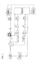
- Fig. 1 is a block diagram of an optical fiber temperature distribution measuring device according to an embodiment of the present invention. Components having the same components in Fig. 9 are given the same reference symbols as the latter and redundant description will be avoided.
- the optical fiber temperature distribution measuring device of Fig. 1 is different from that of Fig. 9 in that in the former a temperature corrector 12 is connected to the arithmetic controller 7.
- the temperature corrector 12 corrects a temperature calculated by the arithmetic controller 7 of the device main body using temperature measurement data of the reference thermometer 11 which is disposed in the vicinity of the optical fiber 3 used as the temperature sensor and a correction formula according to the invention, and outputs a highly accurate temperature measurement result.
- the temperature corrector 12 corrects the temperature calculated by the arithmetic controller 7 as follows. First of all, a temperature T is calculated based on Equation (4) using an intensity ratio between anti-Stokes light AS and Stokes light ST and measurement data of the thermometer 10 which is provided in the temperature reference unit 9.
- the temperature reference unit 9 is incorporated in the device main body.
- T r ⁇ 1 ⁇ r T - ⁇ r T 1 ⁇ ⁇ + ⁇ 1 T 1
- ⁇ 1 corresponds to the Raman shift angular frequency of the optical fiber 3 used as the temperature sensor and is calculated according to the following Equation (6):
- ⁇ 1 ⁇ r ⁇ T 2 ⁇ ⁇ - T 1 ⁇ ⁇ T 1 ⁇ ⁇ ⁇ T 2 ⁇ ⁇ ⁇ T 2 ⁇ T 1 T 2 - T 1
- Equation (6) is used for two-point temperature calibration. If the Raman shift angular frequency of the optical fiber 3 which is used as the temperature sensor is known, it is not necessary to calculate ⁇ 1 according to Equation (6) and one-point calibration can be performed using only T 1 and T 1 '.
- Equation (5) makes it unnecessary to perform a fine adjustment of the shift angular frequency, an adjustment using a coefficient and an offset, or determination of parameters by repetitive calculations. Accordingly, the calibration can be performed in a short time with only a small error.
- the calibration according to Equation (5) will be described below.
- Equation (1) the intensity ratio between anti-Stokes light AS and Stokes light ST that are output from the device main body which incorporates the temperature reference unit 9 is given by the following Equation (7):
- T h ⁇ ⁇ d 2 ⁇ ⁇ k ⁇ 1 - log G + log G 0 T 0 + h ⁇ ⁇ d 2 ⁇ ⁇ kT 0
- ⁇ d is a Raman shift angular frequency that is used as a temperature calculation parameter in the arithmetic controller 7.
- Equation (11) The parameter L 1 in Equation (10) is given by the following Equation (11):
- temperature T is calculated by the arithmetic controller 7 when the temperature of the optical fiber 3 is T r :
- Equation (12) if the shift angular frequency ⁇ r inside the main body and the shift angular frequency ⁇ d used for the calculation are the same, the term involving T 0 on the right side disappears, and thus the temperature T calculated using the optical fiber 3 which is used as the temperature sensor does not depend on the temperature of the main body. Accordingly, to prevent the measured temperature from varying in response to the variation in the temperature of the main body, it is necessary to use a true shift angular frequency of the optical fiber used in the temperature reference unit 9 which is disposed in the device main body.
- the temperature calibration of the optical fiber 3 which is used as the temperature sensor will be described with assumptions that the shift angular frequency of the optical fiber used in the temperature reference unit 9 is known and equal to the shift angular frequency used for the temperature calculation.
- the Raman shift angular frequency ⁇ 1 of the optical fiber 3 can be corrected according to Equation (6) using two reference temperatures T 1 and T 2 measured at the same position by the reference thermometer 11 and values T 1 ' and T 2 ' calculated by the arithmetic controller 7.
- a first temperature is calculated based on the following Equation (14):
- Equation 15 By substituting Equations (7) and (10) into Equation (14), the following Equation (15) is obtained:
- Equation (16) By solving Equation (15) for T r , the following Equation (16) is obtained:
- T 1 h ⁇ ⁇ 1 2 ⁇ ⁇ k ⁇ 1 h ⁇ ⁇ r 2 ⁇ ⁇ kT + log L 1 - log L r + log ⁇ ⁇ G c
- the true temperature Tr is calculated from the temperature T calculated by the arithmetic controller 7.
- the parameter X -logL 1 + logL T - log ⁇ G c can be calculated based on temperature measurement data of the reference thermometer 11 which is disposed in the vicinity of the optical fiber 3.
- Equation (17) the relationship between the actual temperature T r of the optical fiber 3 and the temperature T calculated by the arithmetic controller 7 is given by the following Equation (17):
- Equation (17) If the reference temperature T 1 measured by the reference thermometer 11 is known and the corresponding temperature calculation value is T 1 ', X is calculated from Equation (17) as follows:
- Equation (5) (temperature calibration formula) can be derived as follows as Equation (19):
- Equation (19) for temperature correction clearly shows that the corrected temperature Tr is irrelevant to the difference ⁇ G c between the losses for anti-Stokes light AS and Stokes light ST. This mans that the influence of the losses occurring at the connecting portion between the device main body and the optical fiber 3 which is used as the temperature sensor is also corrected.
- Equation (19) is basically for one-point temperature calibration and is applicable to the case that the Raman shift angular frequency ⁇ 1 of the optical fiber 3 which is used as the sensor is known. Where the Raman shift angular frequency ⁇ 1 is unknown, ⁇ 1 can be calculated by two-point temperature calibration according to Equation (6) (described below).
- Equation (20) is obtained from Equation (1):
- Equation (21) Assuming the true Raman shift angular frequency ⁇ 1 of the optical fiber 3 which is used as the temperature sensor is equal to ⁇ 1 and a temperature T 1 ' has been measured (calculated) before correction with the true temperature T 1 , Equation (21) is given as follows:
- Equation (22) Assuming the true Raman shift angular frequency ⁇ 1 of the optical fiber 3 which is used as the temperature sensor is equal to ⁇ 1 and a temperature T 2 ' has been measured (calculated) before correction with the true temperature T 2 , Equation (22) is given as follows:
- Equation (23) is obtained by subtracting Equation (22) from Equation (21):
- Equation (24) which is the same as Equation (6) is obtained from Equation (23):
- ⁇ 1 ⁇ r ⁇ T 2 ⁇ ⁇ - T 1 ⁇ ⁇ T 1 ⁇ ⁇ ⁇ T 2 ⁇ ⁇ ⁇ T 2 ⁇ T 1 T 2 - T 1
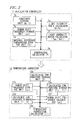
- Fig. 2 is a block diagram of specific examples of the arithmetic controller 7 and the temperature corrector 12.
- the arithmetic controller 7 includes a temperature calculator 7a (main section) for calculating a temperature according to Equation (4), a constants storage unit 7b which is stored with the Planck constant h and the Boltzmann constant k, a Raman shift frequency storage unit 7c for storing a Raman shift angular frequency or of the temperature reference unit 9 which is disposed inside the device, an internal reference temperature storage unit 7d for storing a measured temperature T 0 of the temperature reference unit 9, a light intensity ratio calculator 7e for calculating a light intensity ratio G 0 (T 0 ) in the temperature reference unit 9, a light intensity ratio calculator 7f for calculating a light intensity ratio I as /I st of the optical fiber 3 which is used as the temperature sensor, etc.
- a temperature calculator 7a main section for calculating a temperature according to Equation (4)
- a constants storage unit 7b which is stored with the Planck constant h and the Boltzmann constant k
- a Raman shift frequency storage unit 7c
- the temperature corrector 12 includes a temperature correction calculator 12a (main section) for performing a temperature correcting calculation according to Equations (5) or (19), a calculated temperature storage unit 12b for storing a temperature T calculated by the temperature calculator 7a of the arithmetic controller 7, a Raman shift frequency storage unit 12c for storing a Raman shift angular frequency or of the temperature reference unit 9 which is disposed inside the device, a reference temperature storage unit 12d for storing reference temperatures T 1 and T 2 measured by the reference thermometer 11 which is disposed in the vicinity of the optical fiber 3 which is used as the temperature sensor, a calculated temperatures storage unit 12e for storing temperatures T 1 ' and T 2 ' measured before correction when the reference temperature is T 1 and T 2 , respectively, a Raman shift frequency calculator 12f for calculating a Roman shift angular frequency ⁇ 1 of the optical fiber 3, etc.
- a temperature correction calculator 12a main section for performing a temperature correcting calculation according to Equations (5) or (19)
- a calculated temperature storage unit 12b for
- Fig. 3 is a graph showing an example effect of a temperature correction using the correction formula.
- Parameter values in the correction formula are as follows: Raman shift angular frequency ⁇ r used for temperature calculation before correction: 72.4 x 10 12 rad/Hz Actual temperatures T 1 , T 2 : 295.85 K (22.7°C), 521.25 K (248.1°C) Calculated temperatures T 1 ', T 2 ' before temperature correction: 298.15 K (25.0°C), 540.25 K (267.1°C)
- Temperature measurement errors before the correction are large, for example, about 6°C and about 19°C when the actual temperature is 100°C and 250°C, respectively. This is considered due to connection loss of the device main body and the optical fiber 3 and the difference between the Raman shift angular frequency of the optical fiber and the Raman shift angular frequency of the optical fiber 3.
- temperature measurement errors after the correction using the correction formula are very small, for example, smaller than -0.1 °C and about 0°C when the actual temperature is 100°C and 250°C, respectively.
- the reference thermometer 11 is disposed in the vicinity of the optical fiber 3 and its temperature measurement data are acquired offline and used as calculation parameters in the arithmetic controller 7.
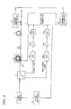
- data of the reference thermometer 11 may be taken in real time (indicated by the solid line in Fig. 4 ) so that the parameters in the temperature calculation formula are varied in real time.
- the reference thermometer 11 cannot be disposed in the vicinity of the optical fiber 3. Even in such a case, it is necessary to determine reference temperatures by a certain method.
- the difference between losses of Stokes wavelength light and anti-Stokes wavelength light in the sensor optical fiber 3 mainly causes a temperature measurement error. It is necessary to determine reference temperatures by removing this above difference.
- JP-A-2004-69685 describes that two separate light sources are provided for the Stokes wavelength and the anti-Stokes wavelength in addition to a DTS optoelectronics module and a temperature correction is calculated by measuring losses of Stokes wavelength light and anti-Stokes wavelength light by determining Rayleigh scattering intensities at the respective wavelengths.
- this method requires the three light sources and thus the system becomes expensive.
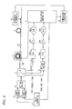
- Fig. 5 is a block diagram of an optical fiber temperature distribution measuring device according to another embodiment of the invention. Components having the same components shown in Fig. 1 or 4 are given the same reference symbols.
- the light source 1a is used for calculating a temperature using an intensity ratio between Stokes light and anti-Stokes light like the light source 1 shown in Figs. 1 and 4 .
- the light source 1b is an anti-Stokes wavelength light source for measuring Rayleigh scattering light at the anti-Stokes wavelength.
- the optical switch 14 switches between output light beams of the light sources 1a and 1b and provides the resulting light to the optical demultiplexer 2.
- the optical demultiplexer 2 is provided with three output ports. A first output port, a second output port, and a third output port are connected to the O/E converter 4st, the O/E converters 4as, and an O/E converter 4rl, respectively.
- the output terminal of the O/E converter 4st is connected to the arithmetic controller 7 via the amplifier 5st and the A/D converter 6st.
- the output terminal of the O/E converter 4as is connected to the arithmetic controller 7 via the amplifier 5as and the A/D converter 6as.
- the output terminal of the O/E converter 4rl is connected to the arithmetic controller 7 via the amplifier 5rl and the A/D converter 6rl.
- the arithmetic controller 7 is connected to the light sources 1a and 1b via the pulse generator 8.
- the O/E converter 4rl, the amplifier 5rl, and the A/D converter 6rl are provided to measure Rayleigh spattering light that is included in light emitted from the light source 1a.
- I as x ⁇ T G as ⁇ P 0 ⁇ L ld x ⁇ L as x ⁇ ⁇ 0 + ⁇ r ⁇ 0 - ⁇ r 4 ⁇ 1 exp h ⁇ ⁇ r 2 ⁇ ⁇ kT - 1
- Equation (26) a Rayleigh scattering light intensity I rld when the light source 1a is used is given by the following Equation (26):
- I rld x P ld ⁇ G rld ⁇ L ld x ⁇ L ld x
- Equation (27) A Rayleigh scattering light intensity I ras when the anti-Stokes wavelength light source 1b is used is given by the following Equation (27):
- I ras x P as ⁇ G ras ⁇ L as x ⁇ L as x
- Equation (25) Equation (25) divided by the square root of the product of Equations (26) and (27), is given by the following Equation (28):
- the anti-Stokes light intensity divided by the square root of the product of the Rayleigh light intensities measured at the anti-Stokes wavelength and the wavelength of the light source 1a is not affected by the losses occurring at the anti-Stokes wavelength and the Rayleigh wavelength. In this manner, a temperature that is not affected by losses occurring at the anti-Stokes wavelength and the Rayleigh wavelength can be calculated.
- G 0 G as ⁇ P 0 P ld ⁇ G rld ⁇ P as ⁇ G ras
- Go of Equation (29) can be calculated as follows by using a value G(X ref , T ref ) that is obtained when a temperature reference unit (located at a position X ref ) shows a known temperature T ref :
- G 0 G x ref ⁇ T ref ⁇ ⁇ 0 - ⁇ ref ⁇ 0 + ⁇ ref 4 ⁇ exp h ⁇ ⁇ ref 2 ⁇ ⁇ k ⁇ T ref - 1
- ⁇ ref is the Raman shift angular frequency of the temperature reference portion.
- T x h ⁇ ⁇ r 2 ⁇ ⁇ k ⁇ log ⁇ 1 G 0 G x ⁇ T ⁇ ⁇ 0 - ⁇ r ⁇ 0 - ⁇ r 4 + 1
- Equation (31) shows that a correct temperature that is not affected by fiber losses can be measured by using G(x, T) which is obtained by dividing an anti-Stokes light intensity by the square root of the product of Rayleigh light intensities measured at the anti-Stokes wavelength and the wavelength of the light source 1a.
- a target temperature can be obtained by correcting a temperature that is measured ordinarily using the ratio between an anti-Stokes light intensity and a Stokes light intensity and using, as a reference temperature, the temperature obtained by the calibration.
- a positive temperature as a reference of correction is measured using Rayleigh light and anti-Stokes light.
- a positive temperature as a reference of correction can also be measured using Rayleigh light and Stokes light in a similar manner.
- the Rayleigh light measuring circuit is provided separately.
- Figs. 6 and 7 show other embodiments which employ an optical switch 15.
- the optical switch 15 provides Rayleigh light, instead of anti-Stokes light or Stokes light, to the anti-Stokes light measuring circuit or the Stokes light measuring circuit.
- the anti-Stokes light measuring circuit or the Stokes light measuring circuit is used as a Rayleigh light measuring circuit.
- a temperature is determine by a correction according to the temperature correction formula using a temperature(s) of the reference thermometer or the temperature reference portion as a parameter(s). Therefore, the calibration work is simplified and can be performed in a short time.
- the present embodiment is suitably applied to temperature distribution measurement, detection of a failure, etc. which use an optical fiber as a sensor.
Landscapes
- Physics & Mathematics (AREA)
- General Physics & Mathematics (AREA)
- Measuring Temperature Or Quantity Of Heat (AREA)
Abstract
Description
- Embodiments described herein relate to an optical fiber temperature distribution measuring device using backward Raman scattering light.
- Among distribution measuring devices using an optical fiber as a sensor, there is a temperature thermometer which measures a temperature distribution along an optical fiber. This technique utilizes backward scattering light that is generated in an optical fiber.
- Among various type of backward scattering light such as Rayleigh scattering light, Brillouin scattering, and Raman scattering light, backward Raman scattering light which has high temperature dependence is used for temperature measurements. A measurement is performed by wavelength-dividing backward Raman scattering light. Backward Raman scattering light has two types, that is, anti-Stokes light AS having a shorter wavelength than incident light and Stokes light ST having a longer wavelength than incident light.
- Optical fiber temperature distribution measuring devices measure anti-Stokes light intensity Ias and Stokes light intensity Ist, calculate a temperature from their ratio, and display a temperature distribution along the optical fiber. Such optical fiber temperature distribution measuring devices are used in such fields of temperature management of plant facilities, research and study relating to disaster prevention, and air-conditioning of big constructions.
-
Fig. 8 is a block diagram showing the configuration of an example basic optical fiber temperature distribution measuring device. As shown inFig. 8 , alight source 1 is connected to an input port of anoptical demultiplexer 2 and anoptical fiber 3 is connected to an input/output port of theoptical demultiplexer 2. A photoelectric converter (hereinafter referred to as an O/E converter) 4st is connected to one output port of theoptical demultiplexer 2 and an O/E converter 4as is connected to the other output port theoptical demultiplexer 2. - An output terminal of the O/E converter 4st is connected to a
arithmetic controller 7 via an amplifier 5st and an A/D converter 6st. An output terminal of the O/E converter 4as is connected to thearithmetic controller 7 via an amplifier 5as and an A/D converter 6as. Thearithmetic controller 7 is connected to thelight source 1 via apulse generator 8. - The
light source 1, which is a laser diode, for example, emits pulse light in synchronism with a timing signal that is supplied from thearithmetic controller 7 via thepulse generator 8. Theoptical demultiplexer 2 receives, at its input port, the pulse light emitted from thelight source 1, and provides the received pulse light to theoptical fiber 3 from its input/output port. Theoptical demultiplexer 2 receives, at its input port, backward Raman scattering light that is generated in theoptical fiber 3 and wavelength-divides the backward Raman scattering light into Stokes light and anti-Stokes light. Theoptical fiber 3 receives, at its input port, the pulse light from theoptical demultiplexer 2, and provides the backward Raman scattering light to theoptical demultiplexer 2 from its input port. - The O/E converters 4st and 4as are photodiodes, for example. The Stokes light that is output from the one output port of the
optical demultiplexer 2 is provided to the O/E converter 4st, and the anti-Stokes light that is output from the other output port of theoptical demultiplexer 2 is provided to the O/E converter 4as. The O/E converters 4st and 4as are configured to generate electrical signals corresponding to the received light beams, respectively. - The amplifiers 5st and 5as amplify the electrical signals that are output from the O/E converters 4st and 4as, respectively. The A/D converters 6st and 6as convert signals that are output from the amplifiers 5st and 5as into digital signals, respectively.
- The
arithmetic controller 7 calculates a temperature based on the digital signals that are output from the A/D converters 6st and 6as, that is, from an intensity ratio between the two components (Stokes light and anti-Stokes light) of the backward scattering light, and displays, on a display unit (not shown), a temperature distribution along theoptical fiber 3 based on a resulting time series of temperatures. A relationship between the intensity ratio and the temperature is stored in thearithmetic controller 7 in advance in the form of a table or a formula. Thearithmetic controller 7 provides the timing signal to thelight source 1 and controls the output timing of light pulses that are output from thelight source 1. - Next, the principle of temperature distribution measurement will be now described. Since the light speed in the
optical fiber 3 is known, a time function representing the signal intensity of each of Stokes light and anti-Stokes light with a light-emitting time point of thelight source 1 as a reference can be converted into a function of the distance along the optical fiber as measured from thelight source 1, that is, a distance distribution in which the horizontal axis represents the distance and the vertical axis is the light intensity of Stokes light or anti-Stokes light generated at each position in theoptical fiber 3. - On the other hand, each of the anti-Stokes light intensity Ias and the Stokes light intensity Ist and their ratio Ias/Ist depend on the temperature of the
optical fiber 3. Therefore, the temperature at a position of generation of Raman scattering light can be obtained if an intensity ratio Ias/Ist becomes known. Since the intensity ratio Ias/Ist is a function Ias(x)/Ist(x) of the distance x, a temperature distribution T(x) along theoptical fiber 3 can be obtained from the intensity ratio Ias(x)/Ist(x). -
Fig. 9 is a block diagram of an optical fiber temperature distribution measuring device in a related art. Components having the same components inFig. 8 are given the same reference symbols as the latter. - As shown in
Fig. 9 , atemperature reference unit 9 having a rolled-up optical fiber of several tens of meters is provided between theoptical demultiplexer 2 and the optical fiber 3 (connected to theoptical fiber 3 via aconnector 13.) Thetemperature reference unit 9 is provided with athermometer 10 which has a platinum resistance thermometer sensor, for example, and configured to measure an actual temperature. An output signal of thethermometer 10 is provided to thearithmetic controller 7. Areference thermometer 11 which has a platinum resistance thermometer sensor, for example, and configured to measure an actual temperature is also provided in the vicinity of theoptical fiber 3 which is used as a temperature sensor. - With the above configuration, when the temperature of the
optical fiber 3 is T (K), the intensity ratio Ias/Ist between anti-Stokes light and Stokes light is given by the following Equation (1): -

- where
- Gas: ratio of an anti-Stokes light gain to a Stokes light gain;
- ω0: angular frequency of an optical signal;
- ωr: Raman shift angular frequency of the
temperature reference unit 9; - h: Planck constant (6.626 × 10⁻³⁴ J·s); and
- k: Boltzmann constant (1.38 × 10⁻²³ J·K-1).
- Although the parameter

- Ln is unknown in an actual system, but Ln can be calculated using temperature data of the
temperature sensor 10 which is provided in thetemperature reference unit 9. - Letting T0 and G0(T0) represent the temperature measured by the
temperature sensor 10 and the corresponding intensity ratio Ias/Ist, respectively. As shown below, Equation (3) is obtained from Equations (1) and (2). -

- Using this value, an equation for calculating a temperature T from an intensity ratio Ias/Ist between anti-Stokes light AS and Stokes light ST is given by:
-

- Actually, an error is caused by a loss occurring at the collecting portion between the device main body and the
optical fiber 3 and the difference between a Raman shift angular frequency of theoptical fiber 3 and a Raman shift angular frequency used in the calculation. Therefore, a true temperature is measured by thereference thermometer 11 which is disposed in the vicinity of theoptical fiber 3, and the Raman shift angular frequency ωr used for the temperature calculation is adjusted finely and a temperature T calculated according to Equation (4) is corrected using a coefficient and an offset. - For example, a coefficient correction and an offset correction are used in the following manner:
- Tr = A × T + C
- Tr: corrected temperature (K);
- T: temperature (K) before correction;
- A: correction coefficient; and
- C: correction offset.
- To eliminate an error that is caused by a loss occurring at the connecting portion and the difference between the Raman shift angular frequency of the optical fiber used in the
temperature reference unit 9 and that of theoptical fiber 3 used as the sensor,JP-A-2008-249515 - However, in the related-art configuration shown in
Fig. 9 , to perform fitting while adjusting the Raman shift angular frequency finely, it is necessary to repeatedly measure a temperature while finely adjusting the Raman shift angular frequency used for the calculation. Thus, the calibration takes long time. - Even after the fine adjustment of the Raman shift angular frequency, a temperature measurement error occurs due to the difference between the Raman shift angular frequency of the optical fiber used in the
temperature reference unit 9 and Raman shift angular frequency of theoptical fiber 3 used as the temperature sensor. - Furthermore, a correction that is performed using a coefficient and an offset is a linear correction whereas the relationship between the Raman scattering intensity and the temperature is nonlinear. This causes large errors at temperatures that are much different from the temperature used for the correction.
- Still further, where the temperature reference unit for providing a reference for temperature calculation outside the device main body, that is, on the path of the optical fiber for measurement, the total configuration becomes complex. The temperature reference unit needs to be constructed at an installation site of the optical fiber for measurement, resulting in a problem that temperature correction work is complicated.
- Exemplary embodiments provide an optical fiber temperature distribution measuring device which can simplify a temperature correction process and increase the correction accuracy.
- According to one or more illustrative aspects of the present invention, there is provided an optical fiber temperature distribution measuring device which measures a temperature distribution along an optical fiber using backward Raman scattering light generated in the optical fiber. The device includes: a reference temperature thermometer disposed in the vicinity of the optical fiber so as to measure a reference temperature of the optical fiber; an arithmetic controller that calculates a temperature of the optical fiber based on the backward Raman scattering light; and a temperature corrector that correct the calculated temperature based on a correction formula containing the reference temperature as a parameter.
- Other aspects and advantages of the present invention will be apparent from the following description, the drawings and the claims.
-
-
Fig. 1 is a block diagram of an optical fiber temperature distribution measuring device according to an embodiment of the invention; -
Fig. 2 is a block diagram of specific examples of a arithmetic controller and a temperature corrector; -
Fig. 3 is a graph showing an example effect of a temperature correction using the correction formula according to the embodiment; -
Fig. 4 is a block diagram showing another embodiment of the invention; -
Fig. 5 is a block diagram showing another embodiment of the invention; -
Fig. 6 is a block diagram showing another embodiment of the invention; -
Fig. 7 is a block diagram showing another embodiment of the invention; -
Fig. 8 is a block diagram showing the configuration of an example basic optical fiber temperature distribution measuring device; and -
Fig. 9 is a block diagram of an optical fiber temperature distribution measuring device in a related art. - Embodiments of the present invention will be hereinafter described in detail with reference to the drawings.
Fig. 1 is a block diagram of an optical fiber temperature distribution measuring device according to an embodiment of the present invention. Components having the same components inFig. 9 are given the same reference symbols as the latter and redundant description will be avoided. The optical fiber temperature distribution measuring device ofFig. 1 is different from that ofFig. 9 in that in the former atemperature corrector 12 is connected to thearithmetic controller 7. - The
temperature corrector 12 corrects a temperature calculated by thearithmetic controller 7 of the device main body using temperature measurement data of thereference thermometer 11 which is disposed in the vicinity of theoptical fiber 3 used as the temperature sensor and a correction formula according to the invention, and outputs a highly accurate temperature measurement result. - For details, the
temperature corrector 12 corrects the temperature calculated by thearithmetic controller 7 as follows.
First of all, a temperature T is calculated based on Equation (4) using an intensity ratio between anti-Stokes light AS and Stokes light ST and measurement data of thethermometer 10 which is provided in thetemperature reference unit 9. Here, thetemperature reference unit 9 is incorporated in the device main body. - Next, the temperature T is corrected based on the following correction formula:
-

- where ω1 corresponds to the Raman shift angular frequency of the
optical fiber 3 used as the temperature sensor and is calculated according to the following Equation (6): -

- where
- ω1: true Raman shift angular frequency;
- ωr: Raman shift angular frequency of the
temperature reference unit 9; - T: temperature (K) before corrected by the
temperature corrector 12; - T1, T2: reference temperatures (K) measured by the
reference thermometer 11; and - T1', T2': temperatures (K) measured before correction when the reference temperature is T1 and T2, respectively.
- Equation (6) is used for two-point temperature calibration. If the Raman shift angular frequency of the
optical fiber 3 which is used as the temperature sensor is known, it is not necessary to calculate ω1 according to Equation (6) and one-point calibration can be performed using only T1 and T1'. - The use of Equation (5) makes it unnecessary to perform a fine adjustment of the shift angular frequency, an adjustment using a coefficient and an offset, or determination of parameters by repetitive calculations. Accordingly, the calibration can be performed in a short time with only a small error. The calibration according to Equation (5) will be described below.
- As can seen from Equation (1), the intensity ratio between anti-Stokes light AS and Stokes light ST that are output from the device main body which incorporates the
temperature reference unit 9 is given by the following Equation (7): -

- where
- Gr(T0): intensity ratio between anti-Stokes light AS and Stokes light ST that are output from the
temperature reference unit 9 when the temperature of thetemperature reference unit 9 is at To; - Gas: ratio of an anti-Stokes light gain to a Stokes light gain;
- ω0: angular frequency of an optical signal; and
- ωr: Raman shift angular frequency of the
temperature reference unit 9. - The parameter Lr is given by the following Equation (8):
-

- On the other hand, a temperature T is calculated by the
arithmetic controller 7 from an intensity ratio Ias/Ist (= G) between anti-Stokes light AS and Stokes light ST as shown in following Equation (9). -

- where ωd is a Raman shift angular frequency that is used as a temperature calculation parameter in the
arithmetic controller 7. - The light intensity ratio Ias/Ist (= G1(Tr)) when the temperature of the
optical fiber 3 which is used as the temperature sensor is Tr is given by the following Equation (10): -

- The parameter L1 in Equation (10) is given by the following Equation (11):
-

- where
- ω1: True Raman shift angular frequency of the
optical fiber 3 which is used as the temperature sensor; and - ΔGc: difference between losses for anti-Stokes light AS and Stokes light ST of the
connector 13 which connects the device main body and theoptical fiber 3. - From Equations (9) and (10), as shown in following Equation (11), temperature T is calculated by the
arithmetic controller 7 when the temperature of theoptical fiber 3 is Tr: -

- As can be seen from Equation (12), if the shift angular frequency ωr inside the main body and the shift angular frequency ωd used for the calculation are the same, the term involving T0 on the right side disappears, and thus the temperature T calculated using the
optical fiber 3 which is used as the temperature sensor does not depend on the temperature of the main body. Accordingly, to prevent the measured temperature from varying in response to the variation in the temperature of the main body, it is necessary to use a true shift angular frequency of the optical fiber used in thetemperature reference unit 9 which is disposed in the device main body. - The temperature calibration of the
optical fiber 3 which is used as the temperature sensor will be described with assumptions that the shift angular frequency of the optical fiber used in thetemperature reference unit 9 is known and equal to the shift angular frequency used for the temperature calculation. - Assuming ωd = ωr in Equation (12), the measured temperature T is expressed as follows:
-

- The Raman shift angular frequency ω1 of the
optical fiber 3 can be corrected according to Equation (6) using two reference temperatures T1 and T2 measured at the same position by thereference thermometer 11 and values T1' and T2' calculated by thearithmetic controller 7. - A first temperature is calculated based on the following Equation (14):
-

- where
- Tr: actual temperature (measured by the reference thermometer 11);
- G1(Tr): intensity ratio between anti-Stokes light AS and Stokes light ST measured using the optical fiber 3 (at the temperature Tr);
- Gr(T0): intensity ratio between anti-Stokes light AS and Stokes light ST measured using the optical fiber of the temperature reference unit 9 (at the reference temperature T0); and
- ωr: Raman shift angular frequency used for the temperature calculation (Raman shift angular frequency of the temperature reference unit 9).
- By substituting Equations (7) and (10) into Equation (14), the following Equation (15) is obtained:
-
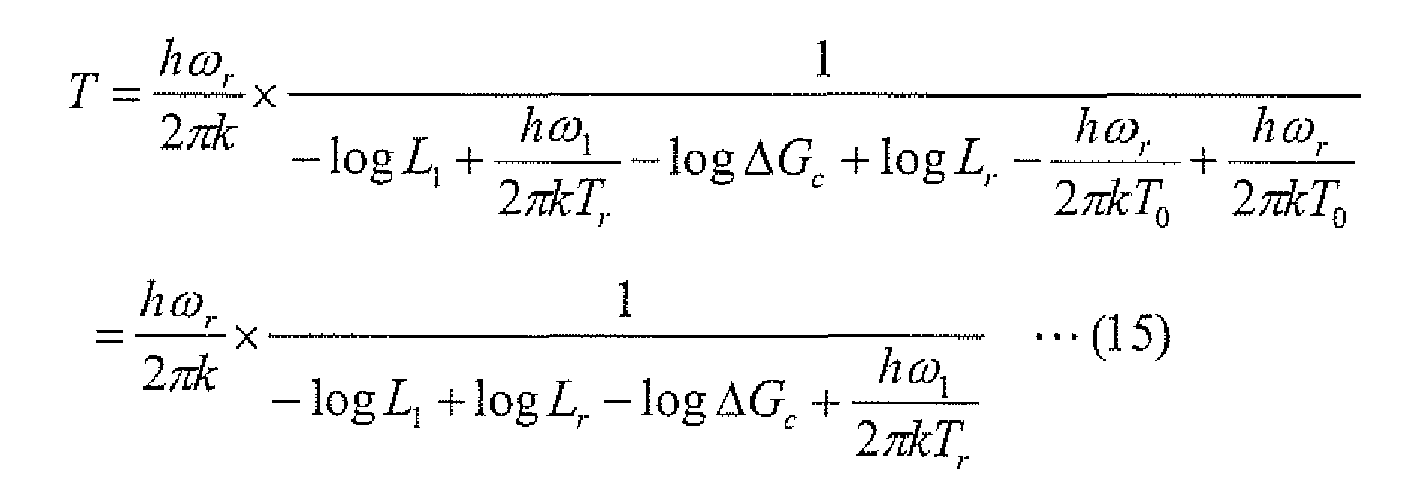
- By solving Equation (15) for Tr, the following Equation (16) is obtained:
-

- According to Equation (16), the true temperature Tr is calculated from the temperature T calculated by the
arithmetic controller 7. The parameter X = -logL1 + logLT - logΔGc can be calculated based on temperature measurement data of thereference thermometer 11 which is disposed in the vicinity of theoptical fiber 3. - By rewriting Equation (13), the relationship between the actual temperature Tr of the
optical fiber 3 and the temperature T calculated by thearithmetic controller 7 is given by the following Equation (17): -

- If the reference temperature T1 measured by the
reference thermometer 11 is known and the corresponding temperature calculation value is T1', X is calculated from Equation (17) as follows: -

- By combining Equations (16) and (18), Equation (5) (temperature calibration formula) can be derived as follows as Equation (19):
-

- where
- T: temperature (K) before correction calculated by the
arithmetic controller 7; - T1: reference temperature (K) measured by the
reference thermometer 11; - T1': temperature (K) measured before correction when the reference temperature is T1
- ω1: true Raman shift angular frequency of the
optical fiber 3; and - ωr: Raman shift angular frequency of the
temperature reference unit 9. - The above process of deriving Equation (19) for temperature correction clearly shows that the corrected temperature Tr is irrelevant to the difference ΔGc between the losses for anti-Stokes light AS and Stokes light ST. This mans that the influence of the losses occurring at the connecting portion between the device main body and the
optical fiber 3 which is used as the temperature sensor is also corrected. - Equation (19) is basically for one-point temperature calibration and is applicable to the case that the Raman shift angular frequency ω1 of the
optical fiber 3 which is used as the sensor is known. Where the Raman shift angular frequency ω1 is unknown, ω1 can be calculated by two-point temperature calibration according to Equation (6) (described below). - The following Equation (20) is obtained from Equation (1):
-

- Assuming the true Raman shift angular frequency ω1 of the
optical fiber 3 which is used as the temperature sensor is equal to ω1 and a temperature T1' has been measured (calculated) before correction with the true temperature T1, Equation (21) is given as follows: -

- Assuming the true Raman shift angular frequency ω1 of the
optical fiber 3 which is used as the temperature sensor is equal to ω1 and a temperature T2' has been measured (calculated) before correction with the true temperature T2, Equation (22) is given as follows: -

- The following Equation (23) is obtained by subtracting Equation (22) from Equation (21):
-

- The following Equation (24) which is the same as Equation (6) is obtained from Equation (23):
-

- where
- ω1: true Raman shift angular frequency of the
optical fiber 3; - ωr: Raman shift angular frequency of the
temperature reference unit 9; - T: temperature (K) before correction calculated by the instrument;
- T1, T2: reference temperatures (K) measured by the
reference thermometer 11; and - T1', T2': temperatures (K) calculated before correction when the reference temperature is T1 and T2, respectively.
-
Fig. 2 is a block diagram of specific examples of thearithmetic controller 7 and thetemperature corrector 12. - The
arithmetic controller 7 includes atemperature calculator 7a (main section) for calculating a temperature according to Equation (4), aconstants storage unit 7b which is stored with the Planck constant h and the Boltzmann constant k, a Raman shiftfrequency storage unit 7c for storing a Raman shift angular frequency or of thetemperature reference unit 9 which is disposed inside the device, an internal referencetemperature storage unit 7d for storing a measured temperature T0 of thetemperature reference unit 9, a lightintensity ratio calculator 7e for calculating a light intensity ratio G0(T0) in thetemperature reference unit 9, a lightintensity ratio calculator 7f for calculating a light intensity ratio Ias/Ist of theoptical fiber 3 which is used as the temperature sensor, etc. - The
temperature corrector 12 includes atemperature correction calculator 12a (main section) for performing a temperature correcting calculation according to Equations (5) or (19), a calculatedtemperature storage unit 12b for storing a temperature T calculated by thetemperature calculator 7a of thearithmetic controller 7, a Raman shiftfrequency storage unit 12c for storing a Raman shift angular frequency or of thetemperature reference unit 9 which is disposed inside the device, a referencetemperature storage unit 12d for storing reference temperatures T1 and T2 measured by thereference thermometer 11 which is disposed in the vicinity of theoptical fiber 3 which is used as the temperature sensor, a calculatedtemperatures storage unit 12e for storing temperatures T1' and T2' measured before correction when the reference temperature is T1 and T2, respectively, a Ramanshift frequency calculator 12f for calculating a Roman shift angular frequency ω1 of theoptical fiber 3, etc. -
Fig. 3 is a graph showing an example effect of a temperature correction using the correction formula. Parameter values in the correction formula are as follows:
Raman shift angular frequency ωr used for temperature calculation before correction: 72.4 x 10¹² rad/Hz
Actual temperatures T1, T2: 295.85 K (22.7°C), 521.25 K (248.1°C)
Calculated temperatures T1', T2' before temperature correction: 298.15 K (25.0°C), 540.25 K (267.1°C) - Temperature measurement errors before the correction are large, for example, about 6°C and about 19°C when the actual temperature is 100°C and 250°C, respectively. This is considered due to connection loss of the device main body and the
optical fiber 3 and the difference between the Raman shift angular frequency of the optical fiber and the Raman shift angular frequency of theoptical fiber 3. In contrast, temperature measurement errors after the correction using the correction formula are very small, for example, smaller than -0.1 °C and about 0°C when the actual temperature is 100°C and 250°C, respectively. - In the above-described embodiment, the
reference thermometer 11 is disposed in the vicinity of theoptical fiber 3 and its temperature measurement data are acquired offline and used as calculation parameters in thearithmetic controller 7. However, where the connection loss of the device main body and theoptical fiber 3 varies, data of thereference thermometer 11 may be taken in real time (indicated by the solid line inFig. 4 ) so that the parameters in the temperature calculation formula are varied in real time. - In actual service, there may be a case that the
reference thermometer 11 cannot be disposed in the vicinity of theoptical fiber 3. Even in such a case, it is necessary to determine reference temperatures by a certain method. In an actual system, the difference between losses of Stokes wavelength light and anti-Stokes wavelength light in the sensoroptical fiber 3 mainly causes a temperature measurement error. It is necessary to determine reference temperatures by removing this above difference. - To eliminate such an error,
JP-A-2004-69685 - In contrast, a configuration shown in
Fig. 5 makes it possible to correct an error due to the difference between losses of Stokes wavelength light and anti-Stokes wavelength light relatively inexpensively.Fig. 5 is a block diagram of an optical fiber temperature distribution measuring device according to another embodiment of the invention. Components having the same components shown inFig. 1 or4 are given the same reference symbols. - As shown in
Fig. 5 , twolight sources optical switch 14 are provided in place of thelight source 1 shown inFigs. 1 and4 . Thelight source 1a is used for calculating a temperature using an intensity ratio between Stokes light and anti-Stokes light like thelight source 1 shown inFigs. 1 and4 . Thelight source 1b is an anti-Stokes wavelength light source for measuring Rayleigh scattering light at the anti-Stokes wavelength. Theoptical switch 14 switches between output light beams of thelight sources optical demultiplexer 2. - The
optical demultiplexer 2 is provided with three output ports. A first output port, a second output port, and a third output port are connected to the O/E converter 4st, the O/E converters 4as, and an O/E converter 4rl, respectively. - The output terminal of the O/E converter 4st is connected to the
arithmetic controller 7 via the amplifier 5st and the A/D converter 6st. The output terminal of the O/E converter 4as is connected to thearithmetic controller 7 via the amplifier 5as and the A/D converter 6as. The output terminal of the O/E converter 4rl is connected to thearithmetic controller 7 via the amplifier 5rl and the A/D converter 6rl. Thearithmetic controller 7 is connected to thelight sources pulse generator 8. The O/E converter 4rl, the amplifier 5rl, and the A/D converter 6rl are provided to measure Rayleigh spattering light that is included in light emitted from thelight source 1a. - A description will be made of a method for correcting an error due to the difference between losses of Stokes wavelength light and anti-Stokes wavelength light in the configuration of
Fig. 5 . An anti-Stokes light intensity corresponding to a detection position x of the photo detector when the temperature at the position x is T (K) is given by the following Equation (25): -

- where
- Gas: anti-Stokes light gain;
- P0: optical power of the
light source 1a when an anti-Stokes light is measured; - L1d(x): one-way loss to the position x of light emitted from the
light source 1a; - Las(x): one-way loss from the position x to the photo detector of anti-Stokes light;
- ω0: angular frequency of light emitted from the
light source 1a; - ωr: Raman shift angular frequency;
- h: Planck constant (6.624 × 10⁻³⁴ J·s);
- k: Boltzmann constant (1.38 × 10⁻²³ J·K-1); and
- T: absolute temperature (K).
- On the other hand, a Rayleigh scattering light intensity Irld when the
light source 1a is used is given by the following Equation (26): -

- A Rayleigh scattering light intensity Iras when the anti-Stokes wavelength
light source 1b is used is given by the following Equation (27): -

- G(x, T), which is defined as Equation (25) divided by the square root of the product of Equations (26) and (27), is given by the following Equation (28):
-

- That is, the anti-Stokes light intensity divided by the square root of the product of the Rayleigh light intensities measured at the anti-Stokes wavelength and the wavelength of the
light source 1a is not affected by the losses occurring at the anti-Stokes wavelength and the Rayleigh wavelength. In this manner, a temperature that is not affected by losses occurring at the anti-Stokes wavelength and the Rayleigh wavelength can be calculated. - A parameters Go is defined as follows:
-

- As can be seen from Equation (28), Go of Equation (29) can be calculated as follows by using a value G(Xref, Tref) that is obtained when a temperature reference unit (located at a position Xref) shows a known temperature Tref:
-

- where ωref is the Raman shift angular frequency of the temperature reference portion.
- From Equations (28) and (29), the temperature T(x) is expressed as follows using G(x, T):
-

- Equation (31) shows that a correct temperature that is not affected by fiber losses can be measured by using G(x, T) which is obtained by dividing an anti-Stokes light intensity by the square root of the product of Rayleigh light intensities measured at the anti-Stokes wavelength and the wavelength of the
light source 1a. - Although the above temperature measurement takes a relatively long time because two kinds of Rayleigh scattering light and one kind of Raman scattering light are measured with high accuracy, in actual, it is adequate that the above temperature measurement be performed only in calibrating the device. A target temperature can be obtained by correcting a temperature that is measured ordinarily using the ratio between an anti-Stokes light intensity and a Stokes light intensity and using, as a reference temperature, the temperature obtained by the calibration.
- As a result, a more accurate temperature measurement can be performed even in the case where losses of anti-Stokes light and Stokes light are varied due to deterioration of the
optical fiber 3. Further, in this case, the above measurement can be implemented at a relatively low cost. - In the above embodiment, a positive temperature as a reference of correction is measured using Rayleigh light and anti-Stokes light. A positive temperature as a reference of correction can also be measured using Rayleigh light and Stokes light in a similar manner.
- In the above embodiment, the Rayleigh light measuring circuit is provided separately.
Figs. 6 and7 show other embodiments which employ anoptical switch 15. Theoptical switch 15 provides Rayleigh light, instead of anti-Stokes light or Stokes light, to the anti-Stokes light measuring circuit or the Stokes light measuring circuit. The anti-Stokes light measuring circuit or the Stokes light measuring circuit is used as a Rayleigh light measuring circuit. - As described above, a temperature is determine by a correction according to the temperature correction formula using a temperature(s) of the reference thermometer or the temperature reference portion as a parameter(s). Therefore, the calibration work is simplified and can be performed in a short time.
- Since a correction is performed according to the correction formula that is derived from the formula of principle, a highly accurate calibration can be realized without an error as occurs in the case of linear approximation. As such, the present embodiment is suitably applied to temperature distribution measurement, detection of a failure, etc. which use an optical fiber as a sensor.
- Furthermore, a more accurate temperature measurement can be performed even in the case where losses of anti-Stokes light and Stokes light are varied due to deterioration of the optical fiber.
Claims (5)
- An optical fiber temperature distribution measuring device which measures a temperature distribution along an optical fiber (3) using backward Raman scattering light generated in the optical fiber, the device comprising:a reference temperature thermometer (11) disposed in the vicinity of the optical fiber so as to measure a reference temperature (T1, T2) of the optical fiber;an arithmetic controller (7) that calculates a temperature (T) of the optical fiber based on the backward Raman scattering light; anda temperature corrector (12) that corrects the calculated temperature (T) based on a correction formula containing the reference temperature as a parameter.
- The device according to claim 1, further comprising:a temperature reference unit (9) that measures a Raman shift angular frequency (ωr),wherein the correction formula contains the reference temperature, the Raman shift angular frequency (ωr) measured by the temperature reference unit, a Raman shift angular frequency (ω0) of the optical fiber as parameters.
- The device according to claim 2, wherein the Raman shift frequency of the optical fiber is calculated based on the reference temperature (T1, T2) and the calculated temperature (T).
- The device according to claim 1,
wherein the temperature corrector receives the reference temperature (T1, T2) from the reference temperature thermometer in real time. - The device according to claim 1,
wherein the temperature corrector measures a reference temperature (T1,T2) of the optical fiber using Rayleigh light and anti-Stokes light or Rayleigh light and Stokes light.
Applications Claiming Priority (2)
| Application Number | Priority Date | Filing Date | Title |
|---|---|---|---|
| JP2010141538 | 2010-06-22 | ||
| JP2010243399A JP5152540B2 (en) | 2010-06-22 | 2010-10-29 | Optical fiber temperature distribution measuring device |
Publications (3)
| Publication Number | Publication Date |
|---|---|
| EP2400284A2 true EP2400284A2 (en) | 2011-12-28 |
| EP2400284A3 EP2400284A3 (en) | 2014-04-30 |
| EP2400284B1 EP2400284B1 (en) | 2016-03-09 |
Family
ID=44736134
Family Applications (1)
| Application Number | Title | Priority Date | Filing Date |
|---|---|---|---|
| EP11170566.1A Active EP2400284B1 (en) | 2010-06-22 | 2011-06-20 | Optical fiber temperature distribution measuring device |
Country Status (3)
| Country | Link |
|---|---|
| US (1) | US8858069B2 (en) |
| EP (1) | EP2400284B1 (en) |
| JP (1) | JP5152540B2 (en) |
Cited By (6)
| Publication number | Priority date | Publication date | Assignee | Title |
|---|---|---|---|---|
| CN102853936A (en) * | 2012-09-12 | 2013-01-02 | 威海北洋电气集团股份有限公司 | Remote distributed fiber Raman temperature sensor |
| CN103335742A (en) * | 2013-07-12 | 2013-10-02 | 杭州欧忆光电科技有限公司 | High-precision distributed optical fiber temperature sensing system |
| CN105334008A (en) * | 2015-11-27 | 2016-02-17 | 中国电力科学研究院 | Performance detecting device for optical fiber type oil temperature sensor for transformer |
| CN106768278A (en) * | 2017-01-06 | 2017-05-31 | 天津大学 | A kind of distributed optical fiber vibration and the double physical quantity sensing positioning systems of temperature |
| CN110907062A (en) * | 2019-12-11 | 2020-03-24 | 山东省科学院激光研究所 | Method and system for improving sampling rate of distributed temperature measurement system |
| CN111307324A (en) * | 2020-03-11 | 2020-06-19 | 中船海洋探测技术研究院有限公司 | Method for compensating APD temperature drift in Raman distributed optical fiber temperature measurement system |
Families Citing this family (15)
| Publication number | Priority date | Publication date | Assignee | Title |
|---|---|---|---|---|
| JP5742861B2 (en) | 2013-02-28 | 2015-07-01 | 横河電機株式会社 | Optical fiber temperature distribution measuring device |
| JP5761235B2 (en) * | 2013-03-06 | 2015-08-12 | 横河電機株式会社 | Optical fiber temperature distribution measuring device |
| CN103364112B (en) * | 2013-07-31 | 2015-10-21 | 北京航空航天大学 | A kind of parameter calibration for temperature-measuring system of distributed fibers and automatic calibrating method |
| JP6201709B2 (en) * | 2013-12-12 | 2017-09-27 | 横河電機株式会社 | Optical fiber temperature distribution measuring device |
| CN103630266A (en) * | 2013-12-16 | 2014-03-12 | 上海华魏光纤传感技术有限公司 | Optical fiber temperature measurement host, optical fiber temperature measurement system and optical fiber temperature measurement method |
| GB2523319B (en) * | 2014-02-19 | 2017-08-16 | Ap Sensing Gmbh | Distributed optical sensing with two-step evaluation |
| DE102014204371A1 (en) * | 2014-03-11 | 2014-11-20 | Siemens Aktiengesellschaft | Method for operating a device for detecting a physical or chemical quantity |
| JP5975064B2 (en) | 2014-05-13 | 2016-08-23 | 横河電機株式会社 | Optical fiber temperature distribution measuring device |
| JP6314678B2 (en) * | 2014-06-16 | 2018-04-25 | 横河電機株式会社 | Optical fiber temperature distribution measuring device |
| JP6206348B2 (en) * | 2014-07-07 | 2017-10-04 | 横河電機株式会社 | Optical fiber temperature distribution measuring device |
| JP6020521B2 (en) * | 2014-07-16 | 2016-11-02 | 横河電機株式会社 | Optical fiber temperature distribution measuring device |
| JP6308184B2 (en) * | 2015-08-24 | 2018-04-11 | 沖電気工業株式会社 | Optical fiber strain measuring device and optical fiber strain measuring method |
| CN108760080B (en) * | 2018-05-18 | 2019-10-08 | 太原理工大学 | A distributed optical fiber Raman temperature measurement device and method based on ASE noise |
| US20240151559A1 (en) * | 2021-03-10 | 2024-05-09 | Nec Corporation | Correction system, correction apparatus, and correction method |
| EP4741786A1 (en) | 2024-11-08 | 2026-05-13 | Telefonica, S.A. | Method, device and system for monitoring temperature in fiber optic networks |
Citations (2)
| Publication number | Priority date | Publication date | Assignee | Title |
|---|---|---|---|---|
| JP2004069685A (en) | 2002-06-21 | 2004-03-04 | Schlumberger Holdings Ltd | Method of measuring and calibrating measured values using an optical fiber distributed sensor |
| JP2008249515A (en) | 2007-03-30 | 2008-10-16 | Occ Corp | Temperature distribution measuring system and temperature distribution measuring method |
Family Cites Families (21)
| Publication number | Priority date | Publication date | Assignee | Title |
|---|---|---|---|---|
| JPH0769223B2 (en) * | 1989-06-08 | 1995-07-26 | 旭硝子株式会社 | Temperature measurement method and distributed optical fiber temperature sensor |
| JPH07218353A (en) * | 1994-02-04 | 1995-08-18 | Nkk Corp | Method and apparatus for measuring temperature distribution by OTDR |
| US6547435B1 (en) * | 1998-05-15 | 2003-04-15 | GESO Gesellschaft für Sensorik, Geotechnischen Umweltschutz und Mathematische Modellierung mbH Jena | Device for monitoring temperature distribution on the basis of distributed fiber-optic sensing, and use of same |
| JP2006517677A (en) * | 2003-02-12 | 2006-07-27 | センサーネットリミテッド | Method and apparatus for generating and transmitting high energy optical pulses for long distance measurements |
| GB0409865D0 (en) * | 2004-05-01 | 2004-06-09 | Sensornet Ltd | Direct measurement of brillouin frequency in distributed optical sensing systems |
| JP2006023260A (en) * | 2004-07-09 | 2006-01-26 | J-Power Systems Corp | Optical fiber temperature distribution measuring method and optical fiber temperature distribution measuring apparatus |
| JP2006071532A (en) * | 2004-09-03 | 2006-03-16 | Hitachi Cable Ltd | Optical fiber temperature distribution sensor |
| JP4874254B2 (en) * | 2004-09-10 | 2012-02-15 | ライオス テヒノロギー ゲーエムベーハー | Calibration of optical FMCW backscattering measurement system |
| US7585107B2 (en) * | 2006-01-17 | 2009-09-08 | Weatherford/Lamb, Inc. | Corrected DTS measurements based on Raman-Stokes signals |
| US7628531B2 (en) * | 2006-03-13 | 2009-12-08 | SensorTran, Inc | Methods and apparatus for dual source calibration for distributed temperature systems |
| CN101421600B (en) * | 2006-04-11 | 2011-11-30 | 萨索特兰公司 | Method and apparatus for calibrating a distributed fiber temperature sensing system |
| US7744275B2 (en) * | 2006-05-31 | 2010-06-29 | Hitachi Cable, Ltd. | Optical fiber temperature sensing device |
| WO2008035436A1 (en) * | 2006-09-22 | 2008-03-27 | J-Power Systems Corporation | Device for measuring temperature distribution of optical fiber and method for measuring temperature distribution of optical fiber |
| US8496376B2 (en) * | 2007-07-18 | 2013-07-30 | Sensortran, Inc. | Dual source auto-correction in distributed temperature systems |
| JP2009174987A (en) * | 2008-01-24 | 2009-08-06 | Hitachi Cable Ltd | Distributed optical fiber temperature sensor |
| CA2738627A1 (en) * | 2008-09-27 | 2010-04-01 | Sensortran, Inc. | Auto-correcting or self-calibrating dts temperature sensing sytems and methods |
| JP2010223831A (en) * | 2009-03-24 | 2010-10-07 | Yokogawa Electric Corp | Temperature measuring device |
| CN101825498B (en) * | 2010-04-13 | 2012-03-21 | 中国计量学院 | Distributed optical fiber Raman temperature sensor (DOFRTS) with self-correction of dispersion and loss spectra |
| WO2012177241A1 (en) * | 2011-06-21 | 2012-12-27 | Halliburton Energy Services, Inc. | Fluid densitometer with temperature sensor to provide temperature correction |
| JP5673830B2 (en) * | 2011-08-15 | 2015-02-18 | 富士通株式会社 | Temperature distribution measuring device and temperature distribution measuring method |
| JP2013092388A (en) * | 2011-10-24 | 2013-05-16 | Yokogawa Electric Corp | Fiber temperature distribution measurement device |
-
2010
- 2010-10-29 JP JP2010243399A patent/JP5152540B2/en active Active
-
2011
- 2011-06-20 EP EP11170566.1A patent/EP2400284B1/en active Active
- 2011-06-21 US US13/164,975 patent/US8858069B2/en active Active
Patent Citations (2)
| Publication number | Priority date | Publication date | Assignee | Title |
|---|---|---|---|---|
| JP2004069685A (en) | 2002-06-21 | 2004-03-04 | Schlumberger Holdings Ltd | Method of measuring and calibrating measured values using an optical fiber distributed sensor |
| JP2008249515A (en) | 2007-03-30 | 2008-10-16 | Occ Corp | Temperature distribution measuring system and temperature distribution measuring method |
Cited By (10)
| Publication number | Priority date | Publication date | Assignee | Title |
|---|---|---|---|---|
| CN102853936A (en) * | 2012-09-12 | 2013-01-02 | 威海北洋电气集团股份有限公司 | Remote distributed fiber Raman temperature sensor |
| CN103335742A (en) * | 2013-07-12 | 2013-10-02 | 杭州欧忆光电科技有限公司 | High-precision distributed optical fiber temperature sensing system |
| CN103335742B (en) * | 2013-07-12 | 2015-04-29 | 杭州欧忆光电科技有限公司 | High-precision distributed optical fiber temperature sensing system |
| CN105334008A (en) * | 2015-11-27 | 2016-02-17 | 中国电力科学研究院 | Performance detecting device for optical fiber type oil temperature sensor for transformer |
| CN105334008B (en) * | 2015-11-27 | 2020-01-17 | 中国电力科学研究院 | An optical fiber oil temperature sensor performance detection device for transformers |
| CN106768278A (en) * | 2017-01-06 | 2017-05-31 | 天津大学 | A kind of distributed optical fiber vibration and the double physical quantity sensing positioning systems of temperature |
| CN106768278B (en) * | 2017-01-06 | 2020-07-31 | 天津大学 | Distributed optical fiber vibration and temperature dual-physical quantity sensing and positioning system |
| CN110907062A (en) * | 2019-12-11 | 2020-03-24 | 山东省科学院激光研究所 | Method and system for improving sampling rate of distributed temperature measurement system |
| CN111307324A (en) * | 2020-03-11 | 2020-06-19 | 中船海洋探测技术研究院有限公司 | Method for compensating APD temperature drift in Raman distributed optical fiber temperature measurement system |
| CN111307324B (en) * | 2020-03-11 | 2022-03-22 | 中船海洋探测技术研究院有限公司 | Method for compensating APD temperature drift in Raman distributed optical fiber temperature measurement system |
Also Published As
| Publication number | Publication date |
|---|---|
| EP2400284A3 (en) | 2014-04-30 |
| JP5152540B2 (en) | 2013-02-27 |
| US20110310925A1 (en) | 2011-12-22 |
| EP2400284B1 (en) | 2016-03-09 |
| US8858069B2 (en) | 2014-10-14 |
| JP2012027001A (en) | 2012-02-09 |
Similar Documents
| Publication | Publication Date | Title |
|---|---|---|
| EP2400284B1 (en) | Optical fiber temperature distribution measuring device | |
| EP2587238B1 (en) | Optical fibre temperature distribution measurement apparatus | |
| CA2692804C (en) | Dual source auto-correction in distributed temperature systems | |
| US9322721B2 (en) | Optic fiber distributed temperature sensor system with self-correction function and temperature measuring method using thereof | |
| US7628531B2 (en) | Methods and apparatus for dual source calibration for distributed temperature systems | |
| EP2966426B1 (en) | Optical fiber temperature distribution measuring device | |
| US7744275B2 (en) | Optical fiber temperature sensing device | |
| JP4421229B2 (en) | Fiber Bragg Grating Physical Quantity Measuring Method and Apparatus | |
| US8368900B2 (en) | Lightwave interferometric distance measuring method and apparatus using an optical comb | |
| EP2944933B1 (en) | Optical fiber temperature distribution measuring device | |
| EP2081006A1 (en) | Optical fiber temperature sensor | |
| EP2977734B1 (en) | Optical fiber temperature distribution measuring device | |
| CN111307324B (en) | Method for compensating APD temperature drift in Raman distributed optical fiber temperature measurement system | |
| JPWO2017029791A1 (en) | Concentration measuring device | |
| CA2646312C (en) | Dual source calibration for distributed temperature systems | |
| EP2975373B1 (en) | Optical fiber temperature distribution measuring device | |
| JP2008249515A (en) | Temperature distribution measuring system and temperature distribution measuring method | |
| JP5382364B2 (en) | Optical fiber temperature distribution measuring device | |
| JP2010223831A (en) | Temperature measuring device | |
| JP2009198389A (en) | Method and device for measuring backward brillouin scattering light of optical fiber | |
| JP6314678B2 (en) | Optical fiber temperature distribution measuring device | |
| JP2011209225A (en) | Device for measuring temperature distribution having temperature distribution calibrating function and method for calibrating temperature distribution | |
| JP2017009509A (en) | Temperature measuring apparatus and temperature measuring method | |
| JPH0823512B2 (en) | Optical fiber linear temperature distribution measuring device | |
| KR100935529B1 (en) | Linear optical fiber distribution temperature measuring device using thermostat |
Legal Events
| Date | Code | Title | Description |
|---|---|---|---|
| AK | Designated contracting states |
Kind code of ref document: A2 Designated state(s): AL AT BE BG CH CY CZ DE DK EE ES FI FR GB GR HR HU IE IS IT LI LT LU LV MC MK MT NL NO PL PT RO RS SE SI SK SM TR |
|
| AX | Request for extension of the european patent |
Extension state: BA ME |
|
| PUAI | Public reference made under article 153(3) epc to a published international application that has entered the european phase |
Free format text: ORIGINAL CODE: 0009012 |
|
| PUAL | Search report despatched |
Free format text: ORIGINAL CODE: 0009013 |
|
| AK | Designated contracting states |
Kind code of ref document: A3 Designated state(s): AL AT BE BG CH CY CZ DE DK EE ES FI FR GB GR HR HU IE IS IT LI LT LU LV MC MK MT NL NO PL PT RO RS SE SI SK SM TR |
|
| AX | Request for extension of the european patent |
Extension state: BA ME |
|
| RIC1 | Information provided on ipc code assigned before grant |
Ipc: G01K 11/32 20060101AFI20140324BHEP Ipc: G01K 15/00 20060101ALI20140324BHEP |
|
| 17P | Request for examination filed |
Effective date: 20141028 |
|
| RBV | Designated contracting states (corrected) |
Designated state(s): AL AT BE BG CH CY CZ DE DK EE ES FI FR GB GR HR HU IE IS IT LI LT LU LV MC MK MT NL NO PL PT RO RS SE SI SK SM TR |
|
| 17Q | First examination report despatched |
Effective date: 20150529 |
|
| GRAP | Despatch of communication of intention to grant a patent |
Free format text: ORIGINAL CODE: EPIDOSNIGR1 |
|
| INTG | Intention to grant announced |
Effective date: 20151006 |
|
| GRAS | Grant fee paid |
Free format text: ORIGINAL CODE: EPIDOSNIGR3 |
|
| GRAA | (expected) grant |
Free format text: ORIGINAL CODE: 0009210 |
|
| AK | Designated contracting states |
Kind code of ref document: B1 Designated state(s): AL AT BE BG CH CY CZ DE DK EE ES FI FR GB GR HR HU IE IS IT LI LT LU LV MC MK MT NL NO PL PT RO RS SE SI SK SM TR |
|
| REG | Reference to a national code |
Ref country code: GB Ref legal event code: FG4D |
|
| REG | Reference to a national code |
Ref country code: AT Ref legal event code: REF Ref document number: 779869 Country of ref document: AT Kind code of ref document: T Effective date: 20160315 Ref country code: CH Ref legal event code: EP |
|
| REG | Reference to a national code |
Ref country code: IE Ref legal event code: FG4D |
|
| REG | Reference to a national code |
Ref country code: DE Ref legal event code: R096 Ref document number: 602011023791 Country of ref document: DE |
|
| REG | Reference to a national code |
Ref country code: LT Ref legal event code: MG4D |
|
| REG | Reference to a national code |
Ref country code: NL Ref legal event code: MP Effective date: 20160309 |
|
| PG25 | Lapsed in a contracting state [announced via postgrant information from national office to epo] |
Ref country code: NO Free format text: LAPSE BECAUSE OF FAILURE TO SUBMIT A TRANSLATION OF THE DESCRIPTION OR TO PAY THE FEE WITHIN THE PRESCRIBED TIME-LIMIT Effective date: 20160609 Ref country code: ES Free format text: LAPSE BECAUSE OF FAILURE TO SUBMIT A TRANSLATION OF THE DESCRIPTION OR TO PAY THE FEE WITHIN THE PRESCRIBED TIME-LIMIT Effective date: 20160309 Ref country code: HR Free format text: LAPSE BECAUSE OF FAILURE TO SUBMIT A TRANSLATION OF THE DESCRIPTION OR TO PAY THE FEE WITHIN THE PRESCRIBED TIME-LIMIT Effective date: 20160309 Ref country code: GR Free format text: LAPSE BECAUSE OF FAILURE TO SUBMIT A TRANSLATION OF THE DESCRIPTION OR TO PAY THE FEE WITHIN THE PRESCRIBED TIME-LIMIT Effective date: 20160610 Ref country code: FI Free format text: LAPSE BECAUSE OF FAILURE TO SUBMIT A TRANSLATION OF THE DESCRIPTION OR TO PAY THE FEE WITHIN THE PRESCRIBED TIME-LIMIT Effective date: 20160309 |
|
| REG | Reference to a national code |
Ref country code: AT Ref legal event code: MK05 Ref document number: 779869 Country of ref document: AT Kind code of ref document: T Effective date: 20160309 |
|
| PG25 | Lapsed in a contracting state [announced via postgrant information from national office to epo] |
Ref country code: RS Free format text: LAPSE BECAUSE OF FAILURE TO SUBMIT A TRANSLATION OF THE DESCRIPTION OR TO PAY THE FEE WITHIN THE PRESCRIBED TIME-LIMIT Effective date: 20160309 Ref country code: SE Free format text: LAPSE BECAUSE OF FAILURE TO SUBMIT A TRANSLATION OF THE DESCRIPTION OR TO PAY THE FEE WITHIN THE PRESCRIBED TIME-LIMIT Effective date: 20160309 Ref country code: PL Free format text: LAPSE BECAUSE OF FAILURE TO SUBMIT A TRANSLATION OF THE DESCRIPTION OR TO PAY THE FEE WITHIN THE PRESCRIBED TIME-LIMIT Effective date: 20160309 Ref country code: LT Free format text: LAPSE BECAUSE OF FAILURE TO SUBMIT A TRANSLATION OF THE DESCRIPTION OR TO PAY THE FEE WITHIN THE PRESCRIBED TIME-LIMIT Effective date: 20160309 Ref country code: LV Free format text: LAPSE BECAUSE OF FAILURE TO SUBMIT A TRANSLATION OF THE DESCRIPTION OR TO PAY THE FEE WITHIN THE PRESCRIBED TIME-LIMIT Effective date: 20160309 Ref country code: NL Free format text: LAPSE BECAUSE OF FAILURE TO SUBMIT A TRANSLATION OF THE DESCRIPTION OR TO PAY THE FEE WITHIN THE PRESCRIBED TIME-LIMIT Effective date: 20160309 |
|
| PG25 | Lapsed in a contracting state [announced via postgrant information from national office to epo] |
Ref country code: IS Free format text: LAPSE BECAUSE OF FAILURE TO SUBMIT A TRANSLATION OF THE DESCRIPTION OR TO PAY THE FEE WITHIN THE PRESCRIBED TIME-LIMIT Effective date: 20160709 Ref country code: EE Free format text: LAPSE BECAUSE OF FAILURE TO SUBMIT A TRANSLATION OF THE DESCRIPTION OR TO PAY THE FEE WITHIN THE PRESCRIBED TIME-LIMIT Effective date: 20160309 |
|
| PG25 | Lapsed in a contracting state [announced via postgrant information from national office to epo] |
Ref country code: SK Free format text: LAPSE BECAUSE OF FAILURE TO SUBMIT A TRANSLATION OF THE DESCRIPTION OR TO PAY THE FEE WITHIN THE PRESCRIBED TIME-LIMIT Effective date: 20160309 Ref country code: CZ Free format text: LAPSE BECAUSE OF FAILURE TO SUBMIT A TRANSLATION OF THE DESCRIPTION OR TO PAY THE FEE WITHIN THE PRESCRIBED TIME-LIMIT Effective date: 20160309 Ref country code: SM Free format text: LAPSE BECAUSE OF FAILURE TO SUBMIT A TRANSLATION OF THE DESCRIPTION OR TO PAY THE FEE WITHIN THE PRESCRIBED TIME-LIMIT Effective date: 20160309 Ref country code: AT Free format text: LAPSE BECAUSE OF FAILURE TO SUBMIT A TRANSLATION OF THE DESCRIPTION OR TO PAY THE FEE WITHIN THE PRESCRIBED TIME-LIMIT Effective date: 20160309 Ref country code: RO Free format text: LAPSE BECAUSE OF FAILURE TO SUBMIT A TRANSLATION OF THE DESCRIPTION OR TO PAY THE FEE WITHIN THE PRESCRIBED TIME-LIMIT Effective date: 20160309 Ref country code: PT Free format text: LAPSE BECAUSE OF FAILURE TO SUBMIT A TRANSLATION OF THE DESCRIPTION OR TO PAY THE FEE WITHIN THE PRESCRIBED TIME-LIMIT Effective date: 20160711 |
|
| REG | Reference to a national code |
Ref country code: DE Ref legal event code: R097 Ref document number: 602011023791 Country of ref document: DE |
|
| PG25 | Lapsed in a contracting state [announced via postgrant information from national office to epo] |
Ref country code: IT Free format text: LAPSE BECAUSE OF FAILURE TO SUBMIT A TRANSLATION OF THE DESCRIPTION OR TO PAY THE FEE WITHIN THE PRESCRIBED TIME-LIMIT Effective date: 20160309 Ref country code: BE Free format text: LAPSE BECAUSE OF FAILURE TO SUBMIT A TRANSLATION OF THE DESCRIPTION OR TO PAY THE FEE WITHIN THE PRESCRIBED TIME-LIMIT Effective date: 20160309 |
|
| PLBE | No opposition filed within time limit |
Free format text: ORIGINAL CODE: 0009261 |
|
| STAA | Information on the status of an ep patent application or granted ep patent |
Free format text: STATUS: NO OPPOSITION FILED WITHIN TIME LIMIT |
|
| PG25 | Lapsed in a contracting state [announced via postgrant information from national office to epo] |
Ref country code: DK Free format text: LAPSE BECAUSE OF FAILURE TO SUBMIT A TRANSLATION OF THE DESCRIPTION OR TO PAY THE FEE WITHIN THE PRESCRIBED TIME-LIMIT Effective date: 20160309 Ref country code: MC Free format text: LAPSE BECAUSE OF FAILURE TO SUBMIT A TRANSLATION OF THE DESCRIPTION OR TO PAY THE FEE WITHIN THE PRESCRIBED TIME-LIMIT Effective date: 20160309 |
|
| REG | Reference to a national code |
Ref country code: CH Ref legal event code: PL |
|
| 26N | No opposition filed |
Effective date: 20161212 |
|
| PG25 | Lapsed in a contracting state [announced via postgrant information from national office to epo] |
Ref country code: BG Free format text: LAPSE BECAUSE OF FAILURE TO SUBMIT A TRANSLATION OF THE DESCRIPTION OR TO PAY THE FEE WITHIN THE PRESCRIBED TIME-LIMIT Effective date: 20160609 |
|
| REG | Reference to a national code |
Ref country code: IE Ref legal event code: MM4A |
|
| REG | Reference to a national code |
Ref country code: FR Ref legal event code: ST Effective date: 20170228 |
|
| PG25 | Lapsed in a contracting state [announced via postgrant information from national office to epo] |
Ref country code: CH Free format text: LAPSE BECAUSE OF NON-PAYMENT OF DUE FEES Effective date: 20160630 Ref country code: FR Free format text: LAPSE BECAUSE OF NON-PAYMENT OF DUE FEES Effective date: 20160630 Ref country code: LI Free format text: LAPSE BECAUSE OF NON-PAYMENT OF DUE FEES Effective date: 20160630 |
|
| PG25 | Lapsed in a contracting state [announced via postgrant information from national office to epo] |
Ref country code: SI Free format text: LAPSE BECAUSE OF FAILURE TO SUBMIT A TRANSLATION OF THE DESCRIPTION OR TO PAY THE FEE WITHIN THE PRESCRIBED TIME-LIMIT Effective date: 20160309 Ref country code: IE Free format text: LAPSE BECAUSE OF NON-PAYMENT OF DUE FEES Effective date: 20160620 |
|
| PG25 | Lapsed in a contracting state [announced via postgrant information from national office to epo] |
Ref country code: CY Free format text: LAPSE BECAUSE OF FAILURE TO SUBMIT A TRANSLATION OF THE DESCRIPTION OR TO PAY THE FEE WITHIN THE PRESCRIBED TIME-LIMIT Effective date: 20160309 Ref country code: HU Free format text: LAPSE BECAUSE OF FAILURE TO SUBMIT A TRANSLATION OF THE DESCRIPTION OR TO PAY THE FEE WITHIN THE PRESCRIBED TIME-LIMIT; INVALID AB INITIO Effective date: 20110620 |
|
| PG25 | Lapsed in a contracting state [announced via postgrant information from national office to epo] |
Ref country code: TR Free format text: LAPSE BECAUSE OF FAILURE TO SUBMIT A TRANSLATION OF THE DESCRIPTION OR TO PAY THE FEE WITHIN THE PRESCRIBED TIME-LIMIT Effective date: 20160309 Ref country code: MK Free format text: LAPSE BECAUSE OF FAILURE TO SUBMIT A TRANSLATION OF THE DESCRIPTION OR TO PAY THE FEE WITHIN THE PRESCRIBED TIME-LIMIT Effective date: 20160309 Ref country code: LU Free format text: LAPSE BECAUSE OF NON-PAYMENT OF DUE FEES Effective date: 20160620 Ref country code: MT Free format text: LAPSE BECAUSE OF NON-PAYMENT OF DUE FEES Effective date: 20160630 |
|
| PG25 | Lapsed in a contracting state [announced via postgrant information from national office to epo] |
Ref country code: AL Free format text: LAPSE BECAUSE OF FAILURE TO SUBMIT A TRANSLATION OF THE DESCRIPTION OR TO PAY THE FEE WITHIN THE PRESCRIBED TIME-LIMIT Effective date: 20160309 |
|
| P01 | Opt-out of the competence of the unified patent court (upc) registered |
Effective date: 20230603 |
|
| PGFP | Annual fee paid to national office [announced via postgrant information from national office to epo] |
Ref country code: GB Payment date: 20240521 Year of fee payment: 14 |
|
| GBPC | Gb: european patent ceased through non-payment of renewal fee |
Effective date: 20250620 |
|
| PG25 | Lapsed in a contracting state [announced via postgrant information from national office to epo] |
Ref country code: GB Free format text: LAPSE BECAUSE OF NON-PAYMENT OF DUE FEES Effective date: 20250620 |
|
| PGFP | Annual fee paid to national office [announced via postgrant information from national office to epo] |
Ref country code: DE Payment date: 20260520 Year of fee payment: 16 |