EP2400136A1 - Detector for internal-combustion engine - Google Patents
Detector for internal-combustion engine Download PDFInfo
- Publication number
- EP2400136A1 EP2400136A1 EP09840326A EP09840326A EP2400136A1 EP 2400136 A1 EP2400136 A1 EP 2400136A1 EP 09840326 A EP09840326 A EP 09840326A EP 09840326 A EP09840326 A EP 09840326A EP 2400136 A1 EP2400136 A1 EP 2400136A1
- Authority
- EP
- European Patent Office
- Prior art keywords
- temperature
- sensor
- heater
- cover
- variation
- Prior art date
- Legal status (The legal status is an assumption and is not a legal conclusion. Google has not performed a legal analysis and makes no representation as to the accuracy of the status listed.)
- Granted
Links
- 238000002485 combustion reaction Methods 0.000 title claims abstract description 63
- 238000001514 detection method Methods 0.000 claims abstract description 67
- 239000003112 inhibitor Substances 0.000 claims description 33
- 239000007789 gas Substances 0.000 description 54
- 230000007423 decrease Effects 0.000 description 38
- 238000005336 cracking Methods 0.000 description 27
- 238000000034 method Methods 0.000 description 22
- 239000000446 fuel Substances 0.000 description 20
- 230000008569 process Effects 0.000 description 17
- 238000002347 injection Methods 0.000 description 14
- 239000007924 injection Substances 0.000 description 14
- 239000001301 oxygen Substances 0.000 description 9
- 229910052760 oxygen Inorganic materials 0.000 description 9
- 230000000875 corresponding effect Effects 0.000 description 8
- 238000010586 diagram Methods 0.000 description 8
- QVGXLLKOCUKJST-UHFFFAOYSA-N atomic oxygen Chemical compound [O] QVGXLLKOCUKJST-UHFFFAOYSA-N 0.000 description 6
- 239000007784 solid electrolyte Substances 0.000 description 6
- 238000005192 partition Methods 0.000 description 5
- 230000006866 deterioration Effects 0.000 description 4
- BASFCYQUMIYNBI-UHFFFAOYSA-N platinum Substances [Pt] BASFCYQUMIYNBI-UHFFFAOYSA-N 0.000 description 4
- 230000004044 response Effects 0.000 description 4
- 239000003054 catalyst Substances 0.000 description 3
- 230000008859 change Effects 0.000 description 3
- 239000003638 chemical reducing agent Substances 0.000 description 3
- 230000001276 controlling effect Effects 0.000 description 3
- 230000003247 decreasing effect Effects 0.000 description 3
- -1 oxygen ions Chemical class 0.000 description 3
- MCMNRKCIXSYSNV-UHFFFAOYSA-N Zirconium dioxide Chemical compound O=[Zr]=O MCMNRKCIXSYSNV-UHFFFAOYSA-N 0.000 description 2
- 229910000420 cerium oxide Inorganic materials 0.000 description 2
- 238000001816 cooling Methods 0.000 description 2
- 238000001914 filtration Methods 0.000 description 2
- 238000010438 heat treatment Methods 0.000 description 2
- 230000003647 oxidation Effects 0.000 description 2
- 238000007254 oxidation reaction Methods 0.000 description 2
- BMMGVYCKOGBVEV-UHFFFAOYSA-N oxo(oxoceriooxy)cerium Chemical compound [Ce]=O.O=[Ce]=O BMMGVYCKOGBVEV-UHFFFAOYSA-N 0.000 description 2
- 229910052697 platinum Inorganic materials 0.000 description 2
- 238000011144 upstream manufacturing Methods 0.000 description 2
- 230000002159 abnormal effect Effects 0.000 description 1
- 230000005856 abnormality Effects 0.000 description 1
- 239000006096 absorbing agent Substances 0.000 description 1
- 230000001464 adherent effect Effects 0.000 description 1
- 230000008901 benefit Effects 0.000 description 1
- 239000011230 binding agent Substances 0.000 description 1
- 238000005524 ceramic coating Methods 0.000 description 1
- 230000002596 correlated effect Effects 0.000 description 1
- 239000010416 ion conductor Substances 0.000 description 1
- 230000004048 modification Effects 0.000 description 1
- 238000012986 modification Methods 0.000 description 1
- 239000011148 porous material Substances 0.000 description 1
- 230000003134 recirculating effect Effects 0.000 description 1
- 239000007787 solid Substances 0.000 description 1
- 230000003068 static effect Effects 0.000 description 1
Images


Classifications
-
- F—MECHANICAL ENGINEERING; LIGHTING; HEATING; WEAPONS; BLASTING
- F02—COMBUSTION ENGINES; HOT-GAS OR COMBUSTION-PRODUCT ENGINE PLANTS
- F02D—CONTROLLING COMBUSTION ENGINES
- F02D41/00—Electrical control of supply of combustible mixture or its constituents
- F02D41/02—Circuit arrangements for generating control signals
- F02D41/14—Introducing closed-loop corrections
- F02D41/1438—Introducing closed-loop corrections using means for determining characteristics of the combustion gases; Sensors therefor
- F02D41/1493—Details
- F02D41/1495—Detection of abnormalities in the air/fuel ratio feedback system
-
- F—MECHANICAL ENGINEERING; LIGHTING; HEATING; WEAPONS; BLASTING
- F01—MACHINES OR ENGINES IN GENERAL; ENGINE PLANTS IN GENERAL; STEAM ENGINES
- F01N—GAS-FLOW SILENCERS OR EXHAUST APPARATUS FOR MACHINES OR ENGINES IN GENERAL; GAS-FLOW SILENCERS OR EXHAUST APPARATUS FOR INTERNAL COMBUSTION ENGINES
- F01N11/00—Monitoring or diagnostic devices for exhaust-gas treatment apparatus, e.g. for catalytic activity
- F01N11/002—Monitoring or diagnostic devices for exhaust-gas treatment apparatus, e.g. for catalytic activity the diagnostic devices measuring or estimating temperature or pressure in, or downstream of the exhaust apparatus
-
- F—MECHANICAL ENGINEERING; LIGHTING; HEATING; WEAPONS; BLASTING
- F01—MACHINES OR ENGINES IN GENERAL; ENGINE PLANTS IN GENERAL; STEAM ENGINES
- F01N—GAS-FLOW SILENCERS OR EXHAUST APPARATUS FOR MACHINES OR ENGINES IN GENERAL; GAS-FLOW SILENCERS OR EXHAUST APPARATUS FOR INTERNAL COMBUSTION ENGINES
- F01N11/00—Monitoring or diagnostic devices for exhaust-gas treatment apparatus, e.g. for catalytic activity
- F01N11/007—Monitoring or diagnostic devices for exhaust-gas treatment apparatus, e.g. for catalytic activity the diagnostic devices measuring oxygen or air concentration downstream of the exhaust apparatus
-
- F—MECHANICAL ENGINEERING; LIGHTING; HEATING; WEAPONS; BLASTING
- F02—COMBUSTION ENGINES; HOT-GAS OR COMBUSTION-PRODUCT ENGINE PLANTS
- F02D—CONTROLLING COMBUSTION ENGINES
- F02D41/00—Electrical control of supply of combustible mixture or its constituents
- F02D41/02—Circuit arrangements for generating control signals
- F02D41/14—Introducing closed-loop corrections
- F02D41/1438—Introducing closed-loop corrections using means for determining characteristics of the combustion gases; Sensors therefor
- F02D41/1493—Details
- F02D41/1494—Control of sensor heater
-
- F—MECHANICAL ENGINEERING; LIGHTING; HEATING; WEAPONS; BLASTING
- F01—MACHINES OR ENGINES IN GENERAL; ENGINE PLANTS IN GENERAL; STEAM ENGINES
- F01N—GAS-FLOW SILENCERS OR EXHAUST APPARATUS FOR MACHINES OR ENGINES IN GENERAL; GAS-FLOW SILENCERS OR EXHAUST APPARATUS FOR INTERNAL COMBUSTION ENGINES
- F01N2550/00—Monitoring or diagnosing the deterioration of exhaust systems
- F01N2550/06—By-pass systems
- F01N2550/12—By-pass systems of particulate filters
-
- F—MECHANICAL ENGINEERING; LIGHTING; HEATING; WEAPONS; BLASTING
- F02—COMBUSTION ENGINES; HOT-GAS OR COMBUSTION-PRODUCT ENGINE PLANTS
- F02D—CONTROLLING COMBUSTION ENGINES
- F02D41/00—Electrical control of supply of combustible mixture or its constituents
- F02D41/02—Circuit arrangements for generating control signals
- F02D41/04—Introducing corrections for particular operating conditions
- F02D41/042—Introducing corrections for particular operating conditions for stopping the engine
-
- F—MECHANICAL ENGINEERING; LIGHTING; HEATING; WEAPONS; BLASTING
- F02—COMBUSTION ENGINES; HOT-GAS OR COMBUSTION-PRODUCT ENGINE PLANTS
- F02D—CONTROLLING COMBUSTION ENGINES
- F02D41/00—Electrical control of supply of combustible mixture or its constituents
- F02D41/02—Circuit arrangements for generating control signals
- F02D41/14—Introducing closed-loop corrections
- F02D41/1438—Introducing closed-loop corrections using means for determining characteristics of the combustion gases; Sensors therefor
- F02D41/1444—Introducing closed-loop corrections using means for determining characteristics of the combustion gases; Sensors therefor characterised by the characteristics of the combustion gases
- F02D41/1446—Introducing closed-loop corrections using means for determining characteristics of the combustion gases; Sensors therefor characterised by the characteristics of the combustion gases the characteristics being exhaust temperatures
-
- F—MECHANICAL ENGINEERING; LIGHTING; HEATING; WEAPONS; BLASTING
- F02—COMBUSTION ENGINES; HOT-GAS OR COMBUSTION-PRODUCT ENGINE PLANTS
- F02D—CONTROLLING COMBUSTION ENGINES
- F02D41/00—Electrical control of supply of combustible mixture or its constituents
- F02D41/02—Circuit arrangements for generating control signals
- F02D41/14—Introducing closed-loop corrections
- F02D41/1438—Introducing closed-loop corrections using means for determining characteristics of the combustion gases; Sensors therefor
- F02D41/1444—Introducing closed-loop corrections using means for determining characteristics of the combustion gases; Sensors therefor characterised by the characteristics of the combustion gases
- F02D41/1454—Introducing closed-loop corrections using means for determining characteristics of the combustion gases; Sensors therefor characterised by the characteristics of the combustion gases the characteristics being an oxygen content or concentration or the air-fuel ratio
-
- Y—GENERAL TAGGING OF NEW TECHNOLOGICAL DEVELOPMENTS; GENERAL TAGGING OF CROSS-SECTIONAL TECHNOLOGIES SPANNING OVER SEVERAL SECTIONS OF THE IPC; TECHNICAL SUBJECTS COVERED BY FORMER USPC CROSS-REFERENCE ART COLLECTIONS [XRACs] AND DIGESTS
- Y02—TECHNOLOGIES OR APPLICATIONS FOR MITIGATION OR ADAPTATION AGAINST CLIMATE CHANGE
- Y02T—CLIMATE CHANGE MITIGATION TECHNOLOGIES RELATED TO TRANSPORTATION
- Y02T10/00—Road transport of goods or passengers
- Y02T10/10—Internal combustion engine [ICE] based vehicles
- Y02T10/40—Engine management systems
Definitions
- the present invention relates to a detection device for an internal combustion engine which detects inhibitors such as particulate matters.
- various sensors such as an air-fuel ratio sensor (A/F sensor) for detecting an air-fuel ratio in the exhaust gas are provided.
- A/F sensor air-fuel ratio sensor
- Patent Reference-1 As a technique for dealing with this, in Patent Reference-1, there is described a technique which determines, at the time when an operation state of a engine is a static state, whether an output value of an oxygen sensor is smaller than a predetermined value or larger than the predetermined value, and which burns up the particulate matters by increasing temperature of an electrical heater for heating up a detection element of the oxygen sensor at the time when the output value is larger than the predetermined value.
- Patent References-2 and -3 there are also described technique which relates to the present invention.
- Patent Reference-1 it is not clear whether the deviation of the output value supplied from the sensor is caused by adhesions of inhibitors or by deterioration of the sensor itself. In the case where the deviation of the output value is caused by the deterioration of the sensor itself, it is meaningless to burn up the particulate matters.
- the present invention has been achieved in order to solve the above problem. It is an object of this invention to provide a detection device for an internal combustion engine which can precisely detect adhesions of inhibitors.
- a detection device for an internal combustion engine which is applied to the internal combustion engine including a temperature varying member, which is provided in an exhaust system, and whose temperature varies due to gas flow in the exhaust system, including a temperature correlation value detection unit which detects a correlation value which correlates with the temperature of the temperature varying member, and a variation calculating unit which calculates a variation of the correlation value, in a time period when the gas flow arises, detected by the temperature correlation value detection unit.
- the above detection device for an internal combustion engine is preferably applied to the internal combustion engine which includes a temperature varying member, which is provided in an exhaust system, and whose temperature varies due to gas flow in the exhaust system.
- the detection device for the internal combustion engine is for example an ECU (Electronic Control Unit) and functions as a temperature correlation value detection unit and a variation calculating unit.
- the temperature correlation value detection unit detects a correlation value which correlates with the temperature of the temperature varying member.
- the term correlation value herein includes impedance of the temperature varying member, a signal output value such as current and voltage sent from the temperature varying member, and the temperature varying member's own temperature.
- the variation calculating unit calculates a variation of the correlation value, in a time period when the gas flow arises, detected by the temperature correlation value detection unit. According to whether or not inhibitors adhere to the temperature varying member, levels of the difficulty in cooling the temperature varying member and the difficulty in heating up the temperature varying member vary and the variation of the correlation value also varies. Thus, by calculating the variation of the temperature varying member, it becomes possible to precisely detect whether or not inhibitors adhere to the temperature varying member.
- the temperature varying member is an electric heater of a gas sensor
- the temperature correlation value detection unit detects impedance of the electric heater as the correlation value
- the temperature varying member is a temperature sensor
- the temperature correlation value detection unit detects a signal output value supplied from the temperature sensor as the correlation value.
- an exhaust temperature sensor which detects temperature of the gas is provided on a streamline which is approximately same as the streamline where the temperature varying member is provided in the exhaust system, and the variation calculating unit calculates a rate of the variation of the correlation value to a variation of an exhaust temperature detected by the exhaust temperature sensor.
- a filter member is provided in the exhaust system, and the temperature varying member is provided at the downstream side of the filter member. Thereby, it becomes possible to determine whether or not the filter is functioning normally.
- a threshold of the variation is set according to an amount of inhibitors which adhere to the temperature varying member, and the detection device further includes a determining unit which determines whether or not the variation calculated by the variation calculating unit is smaller than the threshold.
- the determining unit is an ECU for example. Thereby it is possible to determine whether or not the amount of the inhibitors which adhere to the temperature varying member is larger than the amount of inhibitors corresponding to the threshold.
- FIG. 1 is a configuration diagram which shows a configuration of an internal combustion engine in the first embodiment.
- the solid arrows show the flows of gas and the broken arrows show the flows of signals.
- the internal combustion engine is, for example, a diesel engine which is mounted as a power source for driving on a vehicle such as an automobile, and includes plural cylinders 12, an intake air passage 13 and an exhaust passage 14 which are connected to each of the cylinders 12, and a turbocharger 18 which is arranged in series with the intake air passage 13 and the exhaust passage 14. It is noted that the internal combustion engine may be a gasoline engine instead of the diesel engine.
- an EGR (Exhaust Gas Recirculation) passage 17 for recirculating a part of exhaust gas from the exhaust passage 14 to the intake air passage 13.
- the part of the exhaust gas recirculated by the EGR passage 17 is referred to as the EGR gas.
- An EGR cooler 23 for cooling the EGR gas, and an EGR valve 33 for controlling an amount of the EGR gas are provided on the EGR passage 17. The EGR valve 33 is controlled by the control signal S33 supplied from the ECU 50.
- an air cleaner 21 On the intake air passage 13, there are provided an air cleaner 21, an air flow meter 41 which detects an amount of air (intake air) drawn in from the external, a throttle valve 34 for controlling the intake air amount, a compressor 18a of the turbocharger 18, an intercooler 22, and a surge tank 16 which can store the intake gas (mixed gas of the EGR gas and the intake air) .
- the air flow meter 41 detects the intake air amount and sends the detection signal S41 corresponding to the detected intake air amount to the ECU 50.
- the throttle valve 34 is controlled by the control signal S34 supplied from the ECU 50.
- a turbine 18b of the turbocharger 18, an air-fuel ratio sensor (A/F sensor) 42, and a filter 24 are provided on the exhaust passage 14, a turbine 18b of the turbocharger 18, an air-fuel ratio sensor (A/F sensor) 42, and a filter 24 are provided.
- TheA/F sensor 42 detects an air-fuel ratio in the exhaust gas and sends the detection signal S42 corresponding to the detected air-fuel ratio to the ECU 50.
- the filter 24 collects particulate matters in the exhaust gas.
- the filter is not limited to what only has the filtering function. Instead, what also has a function of a NOx absorber catalyst which absorbs and reduces NOx in the exhaust gas besides the filtering function may be used.
- the turbocharger 18 In the turbocharger 18, the compressor 18a and the turbine 18b are configured to revolve integrally.
- the turbocharger 18, as shown in FIG. 1 may be a variable geometry turbocharger which has a variable nozzle vane 19 and can control the supercharging pressure for example.
- the supercharging pressure is controlled by adjusting the opening degree and controlling the amount of the exhaust gas.
- another supercharger such as an electrical supercharger can be used as the supercharger.
- the intake air passage 13 and the exhaust passage 14 are connected to the combustion chamber 12b of the cylinder 12, and a fuel injection valve 5 for injecting fuel in the combustion chamber 12b is provided on the combustion chamber 12b.
- the fuel injection valve 5 is controlled by the control signal S5 supplied from the ECU 50.
- an intake air valve 3 and an exhaust valve 4 are provided on the cylinder 12.
- the intake air valve 3 controls the flow and cutoff between the intake air passage 13 and the combustion chamber 12b by opening and closing.
- the exhaust valve 4 controls the flow and cutoff between the exhaust passage 14 and the combustion chamber 12b by opening and closing.
- a force which depresses the piston 12c to the bottom dead center is transmitted to the crank shaft 15 via the connecting rod 12d, and then the crank shaft 15 rotates.
- a crank angle sensor 44 is provided near the crank shaft 15. The crank angle sensor 44 detects the rotation angle (crank angle) of the crank shaft 15 and sends the detection signal S44 corresponding to the detected crank angle to the ECU 50.
- the ECU 50 includes a CPU, a ROM, a RAM, an A/D converter, and input-output interfaces, which are not shown, and controls the engine based on the detection signals supplied from various sensors.
- the ECU 50 receives the detection signals supplied from the air flow meter 41, the crank angle sensor 44, and the A/F sensor 42.
- the ECU 50 detects operation state of the engine basedon the detection signals supplied from these various sensors.
- the ECU 50 also receives the detection signals according to each of the pedal opening degrees of the accelerator pedal and the brake pedal supplied from the accelerator sensor 45 and the brake sensor 46.
- the ECU 50 detects the operation request based on the detection signals supplied from these various sensors.
- the ECU 50 sends the control signals to the EGR valve 33, the throttle valve 34, and the fuel injection valve 5 on the basis of the detected operation state and the detected operation request of the engine.
- FIG. 2 is a cross-section diagram showing a configuration of the A/F sensor 42.
- the A/F sensor 42 is a glass-type A/F sensor for example, and includes a sensor element 60, a cover 65, and a heater 68.
- the sensor element 60 includes a solid electrolyte 61, an atmosphere side electrode 62 which is provided on the inner surface of the solid electrolyte 61, an exhaust side electrode 63 which is provided on the outer surface of the solid electrolyte 61, and a ceramic coating 64 which covers the exhaust side electrode 63.
- the heater 68 is provided at the inside of the atmosphere side electrode 62.
- the solid electrolyte 61 is made of zirconia for example and is configured to function (become activated) as an oxygen ion conductor on a hot condition of equal to or higher than 300 degree for example.
- the heater 68 is an electric heater, and heats up and activates the solid electrolyte 61.
- the heater 68 is controlled by the ECU 50.
- the exhaust side electrode 63 and the atmosphere side electrode 62 are porous-platinum electrodes.
- oxygen ions can transfer freely, and if there is a difference (a difference of the oxygen partial pressure) of the oxygen densities in the both ends, the oxygen ions transfer from one side to the other side in order to reduce the density difference.
- This transfer phenomenon of the oxygen ions become the transfers of electrons and generate electromotive force between the pair of electrodes consisting of the exhaust side electrode 63 and the atmosphere side electrode 62.
- This electromotive force becomes the output voltage of the A/F sensor 42, and the larger the difference of the oxygen densities is, the larger the voltage becomes.
- the cover 65 is provided to cover the sensor element 60 and includes an inner cover 66 and an outer cover 67.
- small holes are provided to let the exhaust gas pass through.
- small holes 66a and 67a are provided on the inner cover 66 and the outer cover 67, respectively.
- the holes 66a of the inner cover 66 and the holes 67a of the outer cover 67 are provided not to overlap with each other. It is noted that the holes 66a of the inner cover 66 and the holes 67a of the outer cover 67 may be provided to overlap with each other.
- clogging is likely to happen due to adhesions of inhibitors such as particulate matters in the exhaust gas at the time when the exhaust gas passes.
- a reductant addition valve is set on the exhaust passage 14 at the upstream side of the A/F sensor 42 , droplets of the reductant adhere to these holes of the cover 65 and the inhibitors adhere to the holes by letting the adherent reductant function as a binder and thereby the clogging in the holes of the cover 65 occurs.
- the ECU 50 determines whether or not the clogging in the holes of the cover 65 of the A/F sensor occurs based on a temperature variation of the heater 68 in a predetermined time period.
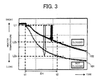
- FIG. 3 shows the graphs each of which indicates the time variation of temperature in the heater 68 of the A/F sensor 42.
- the graph 101 indicates a graph in a case where the clogging in the holes of the cover 65 of the A/F sensor 42 does not occur
- the graph 102 indicates a graph in a case where the clogging in the holes of the cover 65 of the A/F sensor 42 occurs.
- the temperature of the heater 68 is L1 in both of the case where the clogging in the holes of the cover 65 does not occur and the case where the clogging in the holes of the cover 65 occurs.
- the ECU 50 stops the fuel injection by the fuel injection valve 5 thereby to stop the combustion in the cylinders 12 and lets the gas pass through the exhaust passage 14 from the intake air passage 13. In this case, since the cold gas blows down to the A/F sensor 42, the temperature of the heater 68 decrease bit by bit as time goes on.
- the temperature of the heater 68 becomes L2a as indicated by the white arrow in FIG. 3 .
- the temperature of the heater becomes L2b (> L2a) as indicated by the black arrow in FIG. 3 .
- the ECU 50 determines whether or not the amount of the temperature decrease of the heater 68 becomes smaller than a clogging criterion value predetermined in advance.
- the clogging criterion value for example, is set to the amount
- the ECU 50 determines that the clogging in the holes of the cover 65 occurs in the case where the amount of the temperature decrease of the heater 68 is smaller than the clogging criterion value, and determines that the clogging in the holes of the cover 65 does not occur in the case where the amount of the temperature decrease of the heater 68 is equal or larger than the clogging criterion value. Thereby the ECU 50 can detect whether or not the clogging in the holes of the cover 65 of the A/F sensor 42 occurs.
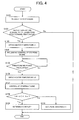
- FIG. 4 is a flow chart indicating the clogging detection method.
- the ECU 50 recognizes a request to stop the engine on the basis of the operation state of the engine and then the process goes to step S102.
- the ECU 50 recognizes the request to stop the engine, for example, due to the change to an idle operation state or a motoring time of a hybrid vehicle which mounts the engine.
- the ECU 50 detects the temperature of the heater 68 and determines whether or not the temperature of the heater 68 is equal to or larger than a predetermined temperature.
- the predetermined temperature is, for example, temperature of the heater 68 at which the A/F sensor 42 is activated.
- the ECU 50 measures the impedance of the heater 68 and then can detect the temperature of the heater 68 on the basis of the impedance measured.
- the ECU 50 determines that the temperature of the heater 68 is equal to or larger than the predetermined temperature (step S102:Yes)
- the process goes to step S103.
- step S102 determines that the temperature of the heater 68 is smaller than the predetermined temperature (step S102: No)
- the ECU 50 executes a normal control process of stopping the engine and then ends the control process.
- step S103 the ECU 50 obtains the temperature L1 of the heater 68 at this time. After then, the ECU 50 proceeds to the process at step S104.
- the ECU 50 executes the preliminary control of stopping the engine. Concretely, by sending the control signal S5 to the fuel injection valve 5 thereby to stop the fuel injection, the ECU 50 stops the combustion in the cylinder 12. Also, by sending the control signal S33 to the EGR valve 33 thereby to let the EGR valve 33 be fully closed, and sending the control signal S34 to the throttle valve 34 thereby to control the opening degrees, the ECU 50 keeps the gas flow amount in the exhaust passage 14 approximately constant. It is noted that, for a variable geometry turbocharger, the ECU 50 additionally controls the opening degrees of the variable nozzle vane 19 in order to keep the gas flow amount in the exhaust passage 14 approximately constant. Thereby it becomes possible to let the cold gas (air) pass through the exhaust passage 14 from the intake air passage 13. After this, the ECU 50 proceeds to the process at step S105.
- step S105 the ECU 50 determines whether or not the predetermined time period ⁇ t has elapsed since the preliminary control of stopping the engine was conducted, and when determining that the predetermined time period ⁇ t has not passed (step S105: No), the ECU 50 repeatedly executes the process at step S105. On the other hand, when determining that the predetermined time period ⁇ t has elapsed (step S105 :Yes), the ECU 50 proceeds to the process at step S106, and for example by measuring the impedance of the heater 68, the ECU 50 obtains the temperature L2 at this time. After this, the ECU 50 proceeds to the process at step S107.
- the ECU 50 executes a control of stopping the engine. Concretely, the ECU 50 decreases the number of engine revolution to 0 and thereby stops the engine completely. After this, the ECU 50 proceeds to the process at step S108.
- the ECU 50 determines whether or not the temperature difference
- the clogging criterion value ⁇ Lc is the amount of the temperature decrease of the heater 68 after the predetermined time period ⁇ t in the case where the clogging in the holes of the cover 65 does not occur.
- the A/F sensor 42 has an abnormality, i.e. , the clogging in the holes of the cover 65 of the A/F sensor 42 occurs (step S110).
- the ECU 50 ends the control process. It is noted that the ECU 50 may execute the processes at step S108 to S110 and the process at step S107 in the inverse order. Namely, the ECU 50 may execute the control of stopping the engine at step S107 after executing the processes at step S108 to S110.
- the ECU 50 lets the cold gas (air) pass through the exhaust passage 14 during the predetermined time period and calculates the amount of the temperature decrease of the heater 68 in the predetermined time period.
- the amount of the temperature decrease of the heater 68 varies due to whether or not the clogging in the holes of the cover 65 of the A/F sensor 42 occurs. Therefore, by calculating the amount of the temperature decrease of the heater 68, the ECU 50 can detect whether or not the clogging in the holes of the cover 65 of the A/F sensor 42 occurs.
- the temperature variation of the heater 68 since the temperature variation of the heater 68 is used, it is possible to precisely detect whether or not the clogging in the holes of the cover 65 occurs without an influence by the degree of deterioration of the sensor element 60.
- FIG. 5 is a configuration diagram showing a part of the exhaust passage of the internal combustion engine in the second embodiment.
- the configuration of the internal combustion engine in the second embodiment has an exhaust temperature sensor 43 on the exhaust passage 14 in addition to the configuration of the internal combustion engine in the first embodiment.
- the exhaust temperature sensor 43 is provided on a streamline which is approximately same as the streamline where the A/F sensor 42 is provided and is exposed to the exhaust gas which has approximately-same temperature as the exhaust gas to which the A/F sensor 42 is exposed.
- an exhaust temperature sensor for estimating the temperature of the filter 24, which is originally provided on the exhaust passage 14 at the upstream side of the filter 24, can be used as this kind of exhaust temperature sensor 43.
- FIG. 6A shows the graphs each of which indicates the time variation of each temperature at the heater 68 of the A/F sensor 42 and the exhaust temperature sensor 43.
- the graph 201 indicates the temperature variation of the heater 68 in the case where the clogging in the holes of the cover 65 of the A/F sensor 42 does not occur
- the graph 202 indicates the temperature variation of the heater 68 in the case where the clogging in the holes of the cover 65 of the A/F sensor 42 occurs
- the graph 203 indicates the variation of the temperature which is detected by the exhaust temperature sensor 43.
- exhaust temperature temperature which is detected by the exhaust temperature sensor 43 is referred to as "exhaust temperature”.
- the ECU 50 stops the fuel injection by the fuel injection valve 5 thereby to stop the combustion in the cylinders 12 and lets the gas pass through the exhaust passage 14 from the intake air passage 13. Temperature which is detected by the exhaust temperature sensor at this time t1 is expressed as "MO”, and temperature of the heater 68 of the A/F sensor 42 at the time t1 is expressed as "L1".
- FIG. 6B shows the graphs each of which indicates the relationship between the temperature of the heater 68 and the exhaust temperature.
- the graphs in FIG. 6A is modified to the graphs each of which indicates the relationship between the temperature of the heater 68 and the exhaust temperature.
- the graph 301 is a graph which indicates the relationship between the temperature of the heater 68 and the exhaust temperature in the case where the clogging in the holes of the cover 65 of the A/F sensor 42 does not occur.
- the graph 302 is a graph which indicates the relationship between the temperature of the heater 68 and the exhaust temperature in the case where the clogging in the holes of the cover 65 of the A/F sensor 42 occurs.
- the graph 302 is curved toward the direction where the temperature of the heater 68 becomes higher.
- the ratio of the temperature variation of the heater 68 to the variation of the exhaust temperature is approximately constant.
- the ratio of the temperature variation of the heater 68 to the variation of the exhaust temperature varies significantly.
- the ratio of the temperature decrease of the heater 68 in the case where the clogging in the holes of the cover 65 of the A/F sensor 42 does not occur becomes approximately constant as indicated by the graph 301.
- the gradients of the tangent lines to the graph 302 becomes larger and larger in response to the decrease of the exhaust temperature to a smaller value than the temperature MO.
- the ratio of the temperature decrease of the heater 68, in the case where the clogging in the holes of the cover 65 of the A/F sensor 42 occurs becomes larger and larger as the exhaust temperature decreases from the temperature MO.
- the ECU 50 calculates the ratio of the temperature variation of the heater 68 to the variation of the exhaust temperature and determines whether or not the ratio of the temperature variation is approximately constant. For example, the ECU 50 detects temperature of the heater 68 per a predetermined time period while the exhaust gas varies, and calculates a map, like what is shown in FIG. 6B , which indicates a relationship between the exhaust temperature and the temperature of the heater 68. Then, by using the map, the ECU 50 calculates the ratio of the temperature variation of the heater 68 to the variation of the exhaust temperature and determines whether or not the ratio calculated is approximately constant.
- the ECU 50 determines that the clogging in the holes of the cover 65 of the A/F sensor 42 does not occur. In contrast, the ECU 50 determines that the clogging in the holes of the cover 65 of the A/F sensor 42 occurs in a case where the ratio calculated is not constant and is changing toward the direction where the temperature of the heater 68 becomes higher over the variation of the exhaust temperature as indicated by the graph 302.
- the ECU 50 determines that the temperature of the heater 68 is changing toward the direction where the temperature of the heater 68 becomes higher and that the clogging in the holes of the cover 65 of the A/F sensor 42 occurs.
- the ECU 50 executes the clogging detection process of the cover 65 of the A/F sensor 42 on the basis of the temperature variation of the exhaust temperature which is detected by the exhaust temperature sensor 43.
- the detection method for the internal combustion engine in the second embodiment without stopping the combustion in the cylinders 12 and significantly decreasing the temperature of the gas which flows in the exhaust passage, only by keeping the flow amount of the exhaust gas approximately constant during the predetermined time period when the exhaust temperature is changing, it is possible to precisely detect whether or not the clogging in the holes of the cover 65 of the A/F sensor 42 occurs.
- the detection method for the internal combustion engine in the second embodiment for example, even at the time of an idle operation state, it is possible to detect whether or not the clogging in the holes of the cover 65 of the A/F sensor 42 occurs.
- the configuration of the internal combustion engine in the third embodiment is the same as the configuration ( FIG. 1 ) of the internal combustion engine in the first embodiment.
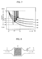
- FIG. 7 similarly to FIG. 3 , shows the graphs each of which indicates the time variation of the temperature of the heater 68 of the A/F sensor 42.
- the graph 401 indicates temperature variation of the heater 68 in the case where the clogging in the holes of the cover 65 of the A/F sensor 42 does not occur and each of the graphs 402 to 404 indicates the temperature variation of the heater 68 in the case where the clogging in the holes of the cover 65 of the A/F sensor 42 occurs.
- the state of the A/F sensor 42 indicated by the graph 404 has the greatest degree of the clogging in the holes of the cover 65, and the state of the A/F sensor 42 indicated by the graph 402 has the smallest degree of the clogging in the holes of the cover 65, out of the all states of the A/F sensor 42 indicated by the graphs 402 to 404.
- the temperature of the heater 68 is L1 in both the case where the clogging in the holes of the cover 65 does not occur and the case where the clogging in the holes of the cover 65 occurs.
- the ECU 50 stops the fuel injection by the fuel injection valve 5 thereby to stop the combustion in the cylinders 12 and lets the gas pass through the exhaust passage 14 from the intake air passage 13.
- the temperature of the heater 68 in the case where the clogging in the holes of the cover 65 does not occur, becomes L2a.
- the temperatures of the heater 68 in the case where the clogging in the holes of the cover 65 occurs, become L2b to L2d.
- the ECU 50 sets a threshold of the amount of the temperature decrease of the heater 68 in accordance with the amounts of inhibitors which adhere to the holes of the cover 65 and then determines whether or not the amount of the temperature decrease of the heater 68 is smaller than the threshold. Thereby it is possible to determine whether or not the amount of the inhibitors which adhere to the holes of the cover 65 is larger than the amount of inhibitors corresponding to the threshold. For example, by setting in advance the threshold in accordance with the limit amount of inhibitors which can be cleared by cleansing the A/F sensor 42, the ECU 50 can determine whether or not inhibitors the amount of which can be cleared by the cleansing adhere to the A/F sensor 42.
- the ECU 50 determines that the inhibitors the amount of which can be cleared by the cleansing adhere to the A/F sensor 42 when the amount of the temperature decrease is smaller than the threshold. At this time, the ECU 50 can inform the driver of the abnormal state where an exchange of the A/F sensor 42 is encouraged, for example, by lighting up a caution-advisory indicator provided on the driving seat.
- the first embodiment is applied as an example, but the second embodiment and the third embodiment can be combined.
- the ECU 50 determines that the temperature of the heater 68 is changing toward the direction which the temperature of the heater 68 becomes higher and that the clogging in the holes of the cover 65 of the A/F sensor 42 occurs in the case where the rate of the temperature decrease of the heater 68 becomes larger and larger as the exhaust temperature decreases from the temperature MO.
- the larger the amount of the inhibitors is, the larger the degree of the temperature increase of the heater 68 becomes. Namely, the graph 302 shown in FIG 6B curves toward the direction where temperature of the heater 68 becomes higher.
- the ECU 50 can determine whether or not the amount of the inhibitors which adhere to the holes of the cover 65 is larger than the amount of inhibitors corresponding to the threshold.
- FIG. 8 is a configuration diagram showing a part of the exhaust passage of the internal combustion engine in the fourth embodiment.
- the A/F sensor 42 is provided on the exhaust passage 14 at the downstream side of the filter 24.
- Other part of the configuration is similar to the configuration ( FIG. 1 ) of the internal combustion engine in the first embodiment.
- the filter 24 has a partition whose pores are open and collects the inhibitors in the exhaust gas by the partition by letting the exhaust gas pass through the partition.
- oxidation catalysts such as platinum (Pt) and cerium oxide (CeO2) are supported and the inhibitors collected is oxidized by the oxidation catalysts. Therefore, when the filter 24 is functioning normally, the inhibitors do not almost adhere to the holes of the cover 65 of the A/F sensor 42 provided on the exhaust passage 14 at downstream side of the filter 24.
- the inhibitors drains into the exhaust passage 14 at downstream side of the filter 24.
- the inhibitors adhere to the holes of the cover 65 of the A/F sensor 42 provided on the exhaust passage 14 at the downstream side of the filter 24 and thereby the clogging occurs.
- the ECU 50 calculates the temperature variation of the heater 68 of the A/F sensor 42 provided on the exhaust passage 14 at the downstream side of the filter 24 and, by using the detection method for the internal combustion engine in the first or the second embodiment, determines whether or not the clogging in the holes of the cover 65 of the A/F sensor 42 occurs. Thereby it becomes possible to determine whether or not the filter 24 is functioning normally.
- the ECU 50 when determining that the clogging in the holes of the cover 65 of the A/F sensor 42 occurs, the ECU 50 can determine that the function of the filter 24 has decreased, and when determining that the clogging in the holes of the cover 65 of the A/F sensor 42 does not occur, the ECU 50 can determine that the function of the filter 24 is functioning normally.
- the ECU 50 determines whether or not the clogging in the holes of the cover 65 occurs on the basis of the temperature variation of the heater 68.
- the gas flow amount to the heater 68 in the case where cracking in the cover 65 occurs is larger than the gas flow amount to the heater 68 in the case where the cracking in the cover 65 does not occur.
- FIG. 9A similarly to FIG. 3 , shows the graphs each of which indicates the time variation of the temperature of the heater 68 of the A/F sensor 42.
- the graph 501 indicates the temperature variation of the heater 68 in the case where both the clogging and the cracking in the cover 65 of the A/F sensor 42 do not occur
- the graph 502 indicates the temperature variation of the heater 68 in the case where the clogging in the holes of the cover 65 of theA/F sensor 42 occurs.
- the graph 503 indicates the temperature variation of the heater 68 in the case where the cracking in the cover 65 of the A/F sensor 42 occurs.
- the ECU 50 stops the fuel injection by the fuel injection valve 5 thereby to stop the combustion in the cylinders 12 and lets the gas pass through the exhaust passage 14 from the intake air passage 13.
- the temperature of the heater 68 in the case where both the clogging and the cracking in the cover 65 do not occur, becomes L2a.
- the temperature of the heater 68 in the case where the clogging in the holes of the cover 65 occurs, becomes L2b (>L2a) and the temperature of the heater 68, in the case where the cracking in the cover 65 occurs, becomes L2bb ( ⁇ L2a).
- the amount of the temperature decrease of the heater 68 over time becomes large because the amount of the gas flow to the heater 68, in the case where the cracking in the cover 65 of the A/F sensor 42 occurs, is larger than that in the case where the cracking in the cover 65 does not occur.
- the ECU 50 not only determines whether or not the clogging in the holes of the cover 65 occurs but also determines whether or not the cover 65 has cracked on the basis of the temperature variation of the heater 68.
- the ECU 50 not only determines whether or not the amount of the temperature decrease of the heater 68 is smaller than a predetermined clogging criterion value but also determines whether or not the amount of the temperature decrease is smaller than a predetermined cracking criterion value.
- the cracking criterion value is a compatible value calculated by experimental trials and is set to a value which is smaller than the clogging criterion value.
- the ECU 50 determines that the cracking in the cover 65 occurs in the case where the amount of the temperature decrease of the heater 68 is smaller than the cracking criterion value, and determines that the cracking in the cover 65 does not occur in the case where the amount of the temperature decrease of the heater 68 is equal to or larger than the cracking criterion value. In other words, the ECU 50 determines that both the clogging and the cracking in the cover 65 of the A/F sensor 42 do not occur when the amount of the temperature decrease of the heater 68 is smaller than the clogging criterion value and equal to or larger than the cracking criterion value.
- FIG. 9B similarly to FIG. 6B , shows the graphs each of which shows the relationship between the temperature of the heater 68 and the exhaust temperature.
- the graph 601 is a graph showing the relationship between the temperature of the heater 68 and the exhaust temperature in the case where both the clogging and the cracking in the cover 65 of the A/F sensor 42 do not occur.
- the graph 602 is a graph showing the relationship between the temperature of the heater 68 and the exhaust temperature in the case where the clogging in the holes of the cover 65 of the A/F sensor 42 occurs.
- the graph 603 is a graph showing the relationship between the temperature of the heater 68 and the exhaust temperature in the case where the cracking in the cover 65 of the A/F sensor 42 occurs.
- the graph 603 is curved toward the direction where the temperature of the heater 68 becomes lower.
- the temperature of the heater 68 in the case where both the clogging and the cracking in the cover 65 of the A/F sensor 42 do not occur, varies at an approximately constant rate to the variation of the exhaust temperature.
- the ratio of the temperature variation of the heater 68 to the variation of the exhaust temperature varies significantly.
- the gradient of the tangent line to the graph 603 becomes smaller and smaller as the exhaust temperature decreases from the temperature MO.
- the ratio of the temperature decrease of the heater 68, in the case where the cracking in the cover 65 of the A/F sensor 42 occurs becomes smaller and smaller.
- the ECU 50 determines how the ratio of the temperature variation of the heater 68 to the variation of the exhaust temperature gradually changes in the case where the ratio of the temperature variation of the heater 68 to the variation of the exhaust temperature is not approximately constant.
- the ECU 50 determines that the clogging in the holes of the cover 65 of the A/F sensor 42 occurs when the temperature of the heater 68 is changing toward the direction where the temperature becomes higher with the change of the exhaust temperature as indicated by the graph 602.
- the ECU 50 determines that the cracking in the cover 65 of the A/F sensor 42 occurs when the temperature of the heater 68 is changing toward the direction where the temperature becomes lower with the change of the exhaust temperature as indicated by the graph 603.
- the ECU 50 determines that the clogging in the holes of the cover 65 of the A/F sensor 42 occurs in the case where the rate of the temperature decrease of the heater 68 is larger and larger as the exhaust temperature decreases from the temperature MO, and determines that the cracking in the cover 65 of the A/F sensor 42 occurs in the case where the rate of the temperature decrease of the heater 68 is smaller and smaller.
- the ECU 50 detects the temperature of the heater 68 based on the impedance of the heater 68 and determine whether or not the clogging in the holes of the cover 65 (or the cracking of the cover 65) occurs on the basis of the amount of temperature variation of the heater 68.
- the ECU 50 may determine whether or not the clogging in the holes of the cover 65 (or the cracking of the cover 65) occurs.
- the ECU 50 may determine whether or not the impedance variation between the time t1 and the time t2 is smaller than the impedance corresponding to the clogging criterion value.
- the present invention is not limited to what is applied to the A/F sensor, but also can be applied to other various sensors.
- the above detection method is executed in order to determine whether or not the clogging in the holes of the cover occurs, but it is not limited to this. Namely, by executing the above detection process for a sensor which does not have a cover, it is also possible to determine whether or not the inhibitors adhere directly to the sensor precisely.
- the present invention can also be applied to a case where a temperature sensor is used.
- the ECU 50 can determine whether or not inhibitors adhere to the temperature sensor on the basis of the temperature variation detected by the temperature sensor.
- the ECU 50 may determine whether or not the inhibitors adhere by using a variation of a signal output value (voltage value and/or current value) correlated with the temperature supplied from the temperature sensor instead of using the temperature variation.
- the present invention is not limited what is applied to sensors but also applied to a temperature varying member whose temperature varies in response to the gas flow in the exhaust passage.
- the present invention is not limited to the above embodiments and these can be accordingly changed in the range where the changes do not go against the gist or the ideas which can be seen in all of the claims and the specification and the embodiments to which the changes is applied is also included in the technical scope of the present invention.
- This invention canbe used for an internal combustion engine which includes a temperature varying member such as a sensor which varies in response to an exhaust temperature.
Landscapes
- Engineering & Computer Science (AREA)
- Chemical & Material Sciences (AREA)
- Combustion & Propulsion (AREA)
- Mechanical Engineering (AREA)
- General Engineering & Computer Science (AREA)
- Chemical Kinetics & Catalysis (AREA)
- Combined Controls Of Internal Combustion Engines (AREA)
- Exhaust Gas After Treatment (AREA)
- Electrical Control Of Air Or Fuel Supplied To Internal-Combustion Engine (AREA)
Abstract
Description
- The present invention relates to a detection device for an internal combustion engine which detects inhibitors such as particulate matters.
- In an exhaust system of an internal combustion engine, various sensors such as an air-fuel ratio sensor (A/F sensor) for detecting an air-fuel ratio in the exhaust gas are provided. When inhibitors such as particulate matters in the exhaust gas adhere to a detection unit of these kinds of sensors, the sensors become unable to obtain accurate detection values, and thereby the detection accuracy is deteriorated. As a technique for dealing with this, in Patent Reference-1, there is described a technique which determines, at the time when an operation state of a engine is a static state, whether an output value of an oxygen sensor is smaller than a predetermined value or larger than the predetermined value, and which burns up the particulate matters by increasing temperature of an electrical heater for heating up a detection element of the oxygen sensor at the time when the output value is larger than the predetermined value. In Patent References-2 and -3, there are also described technique which relates to the present invention.
-
- Patent Reference-1: Japanese Patent Application Laid-open under No. H11-82112
- Patent Reference-2: Japanese Patent No.
3744486 - Patent Reference-3: Japanese Patent No.
3958755 - However, by the technique described in Patent Reference-1, it is not clear whether the deviation of the output value supplied from the sensor is caused by adhesions of inhibitors or by deterioration of the sensor itself. In the case where the deviation of the output value is caused by the deterioration of the sensor itself, it is meaningless to burn up the particulate matters.
- The present invention has been achieved in order to solve the above problem. It is an object of this invention to provide a detection device for an internal combustion engine which can precisely detect adhesions of inhibitors.
- According to one aspect of the present invention, there is provided a detection device for an internal combustion engine which is applied to the internal combustion engine including a temperature varying member, which is provided in an exhaust system, and whose temperature varies due to gas flow in the exhaust system, including a temperature correlation value detection unit which detects a correlation value which correlates with the temperature of the temperature varying member, and a variation calculating unit which calculates a variation of the correlation value, in a time period when the gas flow arises, detected by the temperature correlation value detection unit.
- The above detection device for an internal combustion engine is preferably applied to the internal combustion engine which includes a temperature varying member, which is provided in an exhaust system, and whose temperature varies due to gas flow in the exhaust system. The detection device for the internal combustion engine is for example an ECU (Electronic Control Unit) and functions as a temperature correlation value detection unit and a variation calculating unit. The temperature correlation value detection unit detects a correlation value which correlates with the temperature of the temperature varying member. The term correlation value herein includes impedance of the temperature varying member, a signal output value such as current and voltage sent from the temperature varying member, and the temperature varying member's own temperature. The variation calculating unit calculates a variation of the correlation value, in a time period when the gas flow arises, detected by the temperature correlation value detection unit. According to whether or not inhibitors adhere to the temperature varying member, levels of the difficulty in cooling the temperature varying member and the difficulty in heating up the temperature varying member vary and the variation of the correlation value also varies. Thus, by calculating the variation of the temperature varying member, it becomes possible to precisely detect whether or not inhibitors adhere to the temperature varying member.
- In a preferable embodiment of the detection device for an internal combustion engine, the temperature varying member is an electric heater of a gas sensor, and the temperature correlation value detection unit detects impedance of the electric heater as the correlation value.
- In another preferable embodiment of the detection device for an internal combustion engine, the temperature varying member is a temperature sensor, and the temperature correlation value detection unit detects a signal output value supplied from the temperature sensor as the correlation value.
- In another manner of the detection device for an internal combustion engine, an exhaust temperature sensor which detects temperature of the gas is provided on a streamline which is approximately same as the streamline where the temperature varying member is provided in the exhaust system, and the variation calculating unit calculates a rate of the variation of the correlation value to a variation of an exhaust temperature detected by the exhaust temperature sensor. Thereby it is also possible to precisely detect whether or not inhibitors adhere to the temperature varying member. Additionally, thereby it becomes possible to detect whether or not inhibitors adhere to the temperature varying member only by keeping the gas flow approximately constant during a predetermined time period when the exhaust temperature varies.
- In another manner of the detection device for an internal combustion engine, a filter member is provided in the exhaust system, and the temperature varying member is provided at the downstream side of the filter member. Thereby, it becomes possible to determine whether or not the filter is functioning normally.
- In another manner of the detection device for an internal combustion engine, a threshold of the variation is set according to an amount of inhibitors which adhere to the temperature varying member, and the detection device further includes a determining unit which determines whether or not the variation calculated by the variation calculating unit is smaller than the threshold. The determining unit is an ECU for example. Thereby it is possible to determine whether or not the amount of the inhibitors which adhere to the temperature varying member is larger than the amount of inhibitors corresponding to the threshold.
-
-
FIG. 1 is a configuration diagram which shows a configuration of an internal combustion engine in the first embodiment; -
FIG. 2 is a cross-section diagram showing a configuration of the A/F sensor; -
FIG. 3 shows the graphs indicating the time variation of the temperature of the heater of the A/F sensor; -
FIG. 4 is a flow chart indicating the clogging detection method for the A/F sensor; -
FIG. 5 is a configuration diagram showing a part of the exhaust passage of the internal combustion engine in the second embodiment; -
FIGS. 6A and 6B show the graphs each of which indicates the time variation of each temperature at the heater of the A/F sensor and the exhaust temperature sensor and graphs each of which indicates the relationship between the temperature of the heater and the exhaust temperature. -
FIG. 7 shows graphs each of which indicates the time variation of the temperature of the heater of the A/F sensor; -
FIG. 8 shows a configuration diagram showing a part of the exhaust passage of the internal combustion engine in the fourth embodiment; and -
FIGS. 9A and 9B show the graphs each of which indicates the time variation of the temperature of the heater of the A/F sensor and the graphs each of which indicates the relationship between the temperature of the heater and the exhaust temperature. -
- 3
- Intake air valve
- 4
- Exhaust valve
- 5
- Fuel injection valve
- 12
- Cylinder
- 13
- Intake air passage
- 14
- Exhaust passage
- 17
- EGR passage
- 18
- Turbocharger
- 34
- Throttle valve
- 42
- A/F sensor
- 50
- ECU
- Preferred embodiments of the present invention will be explained hereinafter with reference to the drawings.
- The first embodiment of the present invention will be described.
FIG. 1 is a configuration diagram which shows a configuration of an internal combustion engine in the first embodiment. InFIG. 1 , the solid arrows show the flows of gas and the broken arrows show the flows of signals. - The internal combustion engine (engine) is, for example, a diesel engine which is mounted as a power source for driving on a vehicle such as an automobile, and includes
plural cylinders 12, anintake air passage 13 and anexhaust passage 14 which are connected to each of thecylinders 12, and aturbocharger 18 which is arranged in series with theintake air passage 13 and theexhaust passage 14. It is noted that the internal combustion engine may be a gasoline engine instead of the diesel engine. - On the
exhaust passage 14, there is provided an EGR (Exhaust Gas Recirculation)passage 17 for recirculating a part of exhaust gas from theexhaust passage 14 to theintake air passage 13. Hereinafter, the part of the exhaust gas recirculated by theEGR passage 17 is referred to as the EGR gas. AnEGR cooler 23 for cooling the EGR gas, and anEGR valve 33 for controlling an amount of the EGR gas are provided on theEGR passage 17. TheEGR valve 33 is controlled by the control signal S33 supplied from theECU 50. - On the
intake air passage 13, there are provided anair cleaner 21, anair flow meter 41 which detects an amount of air (intake air) drawn in from the external, athrottle valve 34 for controlling the intake air amount, acompressor 18a of theturbocharger 18, anintercooler 22, and asurge tank 16 which can store the intake gas (mixed gas of the EGR gas and the intake air) . Theair flow meter 41 detects the intake air amount and sends the detection signal S41 corresponding to the detected intake air amount to theECU 50. Thethrottle valve 34 is controlled by the control signal S34 supplied from theECU 50. - On the
exhaust passage 14, aturbine 18b of theturbocharger 18, an air-fuel ratio sensor (A/F sensor) 42, and afilter 24 are provided. TheA/F sensor 42 detects an air-fuel ratio in the exhaust gas and sends the detection signal S42 corresponding to the detected air-fuel ratio to theECU 50. Thefilter 24 collects particulate matters in the exhaust gas. Here, the filter is not limited to what only has the filtering function. Instead, what also has a function of a NOx absorber catalyst which absorbs and reduces NOx in the exhaust gas besides the filtering function may be used. - In the
turbocharger 18, thecompressor 18a and theturbine 18b are configured to revolve integrally. Here, theturbocharger 18, as shown inFIG. 1 , may be a variable geometry turbocharger which has avariable nozzle vane 19 and can control the supercharging pressure for example. In the variable geometry turbocharger, the supercharging pressure is controlled by adjusting the opening degree and controlling the amount of the exhaust gas. It is noted that, instead of theturbocharger 18, another supercharger such as an electrical supercharger can be used as the supercharger. - The
intake air passage 13 and theexhaust passage 14 are connected to thecombustion chamber 12b of thecylinder 12, and afuel injection valve 5 for injecting fuel in thecombustion chamber 12b is provided on thecombustion chamber 12b. Thefuel injection valve 5 is controlled by the control signal S5 supplied from theECU 50. Also, anintake air valve 3 and anexhaust valve 4 are provided on thecylinder 12. Theintake air valve 3 controls the flow and cutoff between theintake air passage 13 and thecombustion chamber 12b by opening and closing. Theexhaust valve 4 controls the flow and cutoff between theexhaust passage 14 and thecombustion chamber 12b by opening and closing. In thecylinder 12, a force which depresses thepiston 12c to the bottom dead center is transmitted to thecrank shaft 15 via the connectingrod 12d, and then thecrank shaft 15 rotates. Here, acrank angle sensor 44 is provided near thecrank shaft 15. Thecrank angle sensor 44 detects the rotation angle (crank angle) of thecrank shaft 15 and sends the detection signal S44 corresponding to the detected crank angle to theECU 50. - The ECU (Electronic Control Unit) 50 includes a CPU, a ROM, a RAM, an A/D converter, and input-output interfaces, which are not shown, and controls the engine based on the detection signals supplied from various sensors. Concretely, the
ECU 50 receives the detection signals supplied from theair flow meter 41, thecrank angle sensor 44, and the A/F sensor 42. TheECU 50 detects operation state of the engine basedon the detection signals supplied from these various sensors. TheECU 50 also receives the detection signals according to each of the pedal opening degrees of the accelerator pedal and the brake pedal supplied from theaccelerator sensor 45 and thebrake sensor 46. TheECU 50 detects the operation request based on the detection signals supplied from these various sensors. TheECU 50 sends the control signals to theEGR valve 33, thethrottle valve 34, and thefuel injection valve 5 on the basis of the detected operation state and the detected operation request of the engine. - Here, a description will be given of a configuration of theA/
F sensor 42 with reference toFIG. 2. FIG. 2 is a cross-section diagram showing a configuration of the A/F sensor 42. - As shown in
FIG. 2 , the A/F sensor 42 is a glass-type A/F sensor for example, and includes asensor element 60, acover 65, and aheater 68. - The
sensor element 60 includes asolid electrolyte 61, anatmosphere side electrode 62 which is provided on the inner surface of thesolid electrolyte 61, anexhaust side electrode 63 which is provided on the outer surface of thesolid electrolyte 61, and aceramic coating 64 which covers theexhaust side electrode 63. Theheater 68 is provided at the inside of theatmosphere side electrode 62. - The
solid electrolyte 61 is made of zirconia for example and is configured to function (become activated) as an oxygen ion conductor on a hot condition of equal to or higher than 300 degree for example. Theheater 68 is an electric heater, and heats up and activates thesolid electrolyte 61. Theheater 68 is controlled by theECU 50. Theexhaust side electrode 63 and theatmosphere side electrode 62 are porous-platinum electrodes. In the inside of thesolid electrolyte 61, oxygen ions can transfer freely, and if there is a difference (a difference of the oxygen partial pressure) of the oxygen densities in the both ends, the oxygen ions transfer from one side to the other side in order to reduce the density difference. This transfer phenomenon of the oxygen ions become the transfers of electrons and generate electromotive force between the pair of electrodes consisting of theexhaust side electrode 63 and theatmosphere side electrode 62. This electromotive force becomes the output voltage of the A/F sensor 42, and the larger the difference of the oxygen densities is, the larger the voltage becomes. - The
cover 65 is provided to cover thesensor element 60 and includes aninner cover 66 and anouter cover 67. - On the
cover 65, small holes are provided to let the exhaust gas pass through. Concretely, as shown inFIG. 2 ,small holes inner cover 66 and theouter cover 67, respectively. In the example shown inFIG. 2 , theholes 66a of theinner cover 66 and theholes 67a of theouter cover 67 are provided not to overlap with each other. It is noted that theholes 66a of theinner cover 66 and theholes 67a of theouter cover 67 may be provided to overlap with each other. - Here, in the holes of the
cover 65, clogging is likely to happen due to adhesions of inhibitors such as particulate matters in the exhaust gas at the time when the exhaust gas passes. For example, in a case where a reductant addition valve is set on theexhaust passage 14 at the upstream side of the A/F sensor 42 , droplets of the reductant adhere to these holes of thecover 65 and the inhibitors adhere to the holes by letting the adherent reductant function as a binder and thereby the clogging in the holes of thecover 65 occurs. Once the clogging in the holes of thecover 65 occurs, it becomes hard for the exhaust gas to reach thesensor element 60 and the detection accuracy of the A/F sensor 42 degrades. For this reason, it is important to know whether or not the clogging in the holes of thecover 65 of the A/F sensor 42 occurs. - Hence, in the detection method for the internal combustion engine in the first embodiment, the
ECU 50 determines whether or not the clogging in the holes of thecover 65 of the A/F sensor occurs based on a temperature variation of theheater 68 in a predetermined time period. A concrete description will be given below. -
FIG. 3 shows the graphs each of which indicates the time variation of temperature in theheater 68 of the A/F sensor 42. Thegraph 101 indicates a graph in a case where the clogging in the holes of thecover 65 of the A/F sensor 42 does not occur, and thegraph 102 indicates a graph in a case where the clogging in the holes of thecover 65 of the A/F sensor 42 occurs. - At the time t1, the temperature of the
heater 68 is L1 in both of the case where the clogging in the holes of thecover 65 does not occur and the case where the clogging in the holes of thecover 65 occurs. At the time t1, theECU 50 stops the fuel injection by thefuel injection valve 5 thereby to stop the combustion in thecylinders 12 and lets the gas pass through theexhaust passage 14 from theintake air passage 13. In this case, since the cold gas blows down to the A/F sensor 42, the temperature of theheater 68 decrease bit by bit as time goes on. - Here, compared to the case where the clogging in the holes of the
cover 65 does not occur, in the case where the clogging in the holes of thecover 65 occurs, it becomes hard for the gas to pass through the holes, and thereby wind force of the gas to thesensor element 60 of the A/F sensor 42 becomes weak and it is difficult for theheater 68 to be cooled by the gas. For this reason, as shown inFIG. 3 , compared to the case (see the graph 101) where the clogging in the holes of thecover 65 does not occur, in the case (see the graph 102) where the clogging in the holes of thecover 65 occurs, the amount of the temperature decrease over time becomes smaller. For example, at the time t2 when a predetermined time period Δt has elapsed since the time t1, in the case where the clogging in the holes of thecover 65 does not occur, the temperature of theheater 68 becomes L2a as indicated by the white arrow inFIG. 3 . In contrast, in the case where the clogging in the holes of thecover 65 occurs, the temperature of the heater becomes L2b (> L2a) as indicated by the black arrow inFIG. 3 . - Hence, in the detection method for the internal combustion engine in the first embodiment, at the time t2, the
ECU 50 determines whether or not the amount of the temperature decrease of theheater 68 becomes smaller than a clogging criterion value predetermined in advance. Here, the clogging criterion value, for example, is set to the amount |L2a-L1| (corresponding to the length of the white arrow inFIG. 3 ) of the temperature decrease of theheater 68 in the case where the clogging in the holes of thecover 65 does not occur. TheECU 50 determines that the clogging in the holes of thecover 65 occurs in the case where the amount of the temperature decrease of theheater 68 is smaller than the clogging criterion value, and determines that the clogging in the holes of thecover 65 does not occur in the case where the amount of the temperature decrease of theheater 68 is equal or larger than the clogging criterion value. Thereby theECU 50 can detect whether or not the clogging in the holes of thecover 65 of the A/F sensor 42 occurs. - Next, a description will be given of the above clogging detection method which detects the clogging of the
cover 65 of the A/F sensor 42 with reference toFIG. 4. FIG. 4 is a flow chart indicating the clogging detection method. - At step S101, the
ECU 50 recognizes a request to stop the engine on the basis of the operation state of the engine and then the process goes to step S102. TheECU 50 recognizes the request to stop the engine, for example, due to the change to an idle operation state or a motoring time of a hybrid vehicle which mounts the engine. - At step S102, the
ECU 50 detects the temperature of theheater 68 and determines whether or not the temperature of theheater 68 is equal to or larger than a predetermined temperature. Here, the predetermined temperature is, for example, temperature of theheater 68 at which the A/F sensor 42 is activated. TheECU 50, for example, measures the impedance of theheater 68 and then can detect the temperature of theheater 68 on the basis of the impedance measured. When theECU 50 determines that the temperature of theheater 68 is equal to or larger than the predetermined temperature (step S102:Yes), the process goes to step S103. On the other hand, when determining that the temperature of theheater 68 is smaller than the predetermined temperature (step S102: No), theECU 50 executes a normal control process of stopping the engine and then ends the control process. - At step S103, the
ECU 50 obtains the temperature L1 of theheater 68 at this time. After then, theECU 50 proceeds to the process at step S104. - At step S104, the
ECU 50 executes the preliminary control of stopping the engine. Concretely, by sending the control signal S5 to thefuel injection valve 5 thereby to stop the fuel injection, theECU 50 stops the combustion in thecylinder 12. Also, by sending the control signal S33 to theEGR valve 33 thereby to let theEGR valve 33 be fully closed, and sending the control signal S34 to thethrottle valve 34 thereby to control the opening degrees, theECU 50 keeps the gas flow amount in theexhaust passage 14 approximately constant. It is noted that, for a variable geometry turbocharger, theECU 50 additionally controls the opening degrees of thevariable nozzle vane 19 in order to keep the gas flow amount in theexhaust passage 14 approximately constant. Thereby it becomes possible to let the cold gas (air) pass through theexhaust passage 14 from theintake air passage 13. After this, theECU 50 proceeds to the process at step S105. - At step S105, the
ECU 50 determines whether or not the predetermined time period Δt has elapsed since the preliminary control of stopping the engine was conducted, and when determining that the predetermined time period Δt has not passed (step S105: No), theECU 50 repeatedly executes the process at step S105. On the other hand, when determining that the predetermined time period Δt has elapsed (step S105 :Yes), theECU 50 proceeds to the process at step S106, and for example by measuring the impedance of theheater 68, theECU 50 obtains the temperature L2 at this time. After this, theECU 50 proceeds to the process at step S107. - At step S107, the
ECU 50 executes a control of stopping the engine. Concretely, theECU 50 decreases the number of engine revolution to 0 and thereby stops the engine completely. After this, theECU 50 proceeds to the process at step S108. - At step S108, the
ECU 50 determines whether or not the temperature difference |L2-L1| of the temperatures of theheater 68 is smaller than the clogging criterion value ΔLc. Here, the clogging criterion value ΔLc is the amount of the temperature decrease of theheater 68 after the predetermined time period Δt in the case where the clogging in the holes of thecover 65 does not occur. When determining that the temperature difference |L2-L1| is smaller than the clogging criterion value ΔLc (step S108:Yes), theECU 50 determines that the A/F sensor 42 is functioning normally, i.e., the clogging in the holes of thecover 65 of the A/F sensor 42 does not occur (step S109). On the other hand, when determining that the temperature difference |L2-L1| is equal to or larger than the clogging criterion value ΔLc (step S108:No), the A/F sensor 42 has an abnormality, i.e. , the clogging in the holes of thecover 65 of the A/F sensor 42 occurs (step S110). After executing the processes at step S109 or step S110, theECU 50 ends the control process. It is noted that theECU 50 may execute the processes at step S108 to S110 and the process at step S107 in the inverse order. Namely, theECU 50 may execute the control of stopping the engine at step S107 after executing the processes at step S108 to S110. - As described above, in the detection method for the internal combustion engine in the first embodiment, the
ECU 50 lets the cold gas (air) pass through theexhaust passage 14 during the predetermined time period and calculates the amount of the temperature decrease of theheater 68 in the predetermined time period. The amount of the temperature decrease of theheater 68 varies due to whether or not the clogging in the holes of thecover 65 of the A/F sensor 42 occurs. Therefore, by calculating the amount of the temperature decrease of theheater 68, theECU 50 can detect whether or not the clogging in the holes of thecover 65 of the A/F sensor 42 occurs. Also, in the detection method for the internal combustion engine in the first embodiment, since the temperature variation of theheater 68 is used, it is possible to precisely detect whether or not the clogging in the holes of thecover 65 occurs without an influence by the degree of deterioration of thesensor element 60. - Next, the second embodiment of the present invention will be described below.
-
FIG. 5 is a configuration diagram showing a part of the exhaust passage of the internal combustion engine in the second embodiment. The configuration of the internal combustion engine in the second embodiment has anexhaust temperature sensor 43 on theexhaust passage 14 in addition to the configuration of the internal combustion engine in the first embodiment. Concretely, theexhaust temperature sensor 43 is provided on a streamline which is approximately same as the streamline where the A/F sensor 42 is provided and is exposed to the exhaust gas which has approximately-same temperature as the exhaust gas to which the A/F sensor 42 is exposed. For example, an exhaust temperature sensor for estimating the temperature of thefilter 24, which is originally provided on theexhaust passage 14 at the upstream side of thefilter 24, can be used as this kind ofexhaust temperature sensor 43. -
FIG. 6A shows the graphs each of which indicates the time variation of each temperature at theheater 68 of the A/F sensor 42 and theexhaust temperature sensor 43. Thegraph 201 indicates the temperature variation of theheater 68 in the case where the clogging in the holes of thecover 65 of the A/F sensor 42 does not occur, and thegraph 202 indicates the temperature variation of theheater 68 in the case where the clogging in the holes of thecover 65 of the A/F sensor 42 occurs, and thegraph 203 indicates the variation of the temperature which is detected by theexhaust temperature sensor 43. Hereinafter, temperature which is detected by theexhaust temperature sensor 43 is referred to as "exhaust temperature". - At the time t1, the
ECU 50 stops the fuel injection by thefuel injection valve 5 thereby to stop the combustion in thecylinders 12 and lets the gas pass through theexhaust passage 14 from theintake air passage 13. Temperature which is detected by the exhaust temperature sensor at this time t1 is expressed as "MO", and temperature of theheater 68 of the A/F sensor 42 at the time t1 is expressed as "L1". -
FIG. 6B shows the graphs each of which indicates the relationship between the temperature of theheater 68 and the exhaust temperature. InFIG. 6B , the graphs inFIG. 6A is modified to the graphs each of which indicates the relationship between the temperature of theheater 68 and the exhaust temperature. Thegraph 301 is a graph which indicates the relationship between the temperature of theheater 68 and the exhaust temperature in the case where the clogging in the holes of thecover 65 of the A/F sensor 42 does not occur. Thegraph 302 is a graph which indicates the relationship between the temperature of theheater 68 and the exhaust temperature in the case where the clogging in the holes of thecover 65 of the A/F sensor 42 occurs. - As shown in
FIG. 6B , whereas thegraph 301 is approximately linear, thegraph 302 is curved toward the direction where the temperature of theheater 68 becomes higher. As indicated by thegraph 301, in the case where the clogging in the holes of thecover 65 of the A/F sensor 42 does not occur, the ratio of the temperature variation of theheater 68 to the variation of the exhaust temperature is approximately constant. In contrast, as indicated by thegraph 302, in the case where the clogging in the holes of thecover 65 of the A/F sensor 42 occurs, the ratio of the temperature variation of theheater 68 to the variation of the exhaust temperature varies significantly. - For example, in response to the decrease of the exhaust temperature to a smaller value than the temperature MO, the ratio of the temperature decrease of the
heater 68 in the case where the clogging in the holes of thecover 65 of the A/F sensor 42 does not occur becomes approximately constant as indicated by thegraph 301. On the other hand, as indicated by the tangent lines IL1, IL2 to thegraph 302, the gradients of the tangent lines to thegraph 302 becomes larger and larger in response to the decrease of the exhaust temperature to a smaller value than the temperature MO. In other words, the ratio of the temperature decrease of theheater 68, in the case where the clogging in the holes of thecover 65 of the A/F sensor 42 occurs, becomes larger and larger as the exhaust temperature decreases from the temperature MO. - Hence, in the detection method for the in the internal combustion engine in the second embodiment, the
ECU 50 calculates the ratio of the temperature variation of theheater 68 to the variation of the exhaust temperature and determines whether or not the ratio of the temperature variation is approximately constant. For example, theECU 50 detects temperature of theheater 68 per a predetermined time period while the exhaust gas varies, and calculates a map, like what is shown inFIG. 6B , which indicates a relationship between the exhaust temperature and the temperature of theheater 68. Then, by using the map, theECU 50 calculates the ratio of the temperature variation of theheater 68 to the variation of the exhaust temperature and determines whether or not the ratio calculated is approximately constant. When determining that the ratio calculated is approximately constant, theECU 50 determines that the clogging in the holes of thecover 65 of the A/F sensor 42 does not occur. In contrast, theECU 50 determines that the clogging in the holes of thecover 65 of the A/F sensor 42 occurs in a case where the ratio calculated is not constant and is changing toward the direction where the temperature of theheater 68 becomes higher over the variation of the exhaust temperature as indicated by thegraph 302. For example, in the case where the ratio of the temperature decrease of theheater 68 becomes larger and larger as the exhaust temperature decreases from the temperature MO, theECU 50 determines that the temperature of theheater 68 is changing toward the direction where the temperature of theheater 68 becomes higher and that the clogging in the holes of thecover 65 of the A/F sensor 42 occurs. - As described above, in the detection method for the in the internal combustion engine in the second embodiment, similarly to the detection method for the internal combustion engine in the first embodiment, since the temperature variation of the
heater 68 is used, it is possible to precisely detect whether or not the clogging in the holes of thecover 65 occurs without the influence by the degree of deterioration of thesensor element 60. Furthermore, in the detection method for the internal combustion engine in the second embodiment, theECU 50 executes the clogging detection process of thecover 65 of the A/F sensor 42 on the basis of the temperature variation of the exhaust temperature which is detected by theexhaust temperature sensor 43. Therefore, in the detection method for the internal combustion engine in the second embodiment, without stopping the combustion in thecylinders 12 and significantly decreasing the temperature of the gas which flows in the exhaust passage, only by keeping the flow amount of the exhaust gas approximately constant during the predetermined time period when the exhaust temperature is changing, it is possible to precisely detect whether or not the clogging in the holes of thecover 65 of the A/F sensor 42 occurs. Thus, in the detection method for the internal combustion engine in the second embodiment, for example, even at the time of an idle operation state, it is possible to detect whether or not the clogging in the holes of thecover 65 of the A/F sensor 42 occurs. - Next, the third embodiment of the present invention will be described. The configuration of the internal combustion engine in the third embodiment is the same as the configuration (
FIG. 1 ) of the internal combustion engine in the first embodiment. -
FIG. 7 , similarly toFIG. 3 , shows the graphs each of which indicates the time variation of the temperature of theheater 68 of the A/F sensor 42. Thegraph 401 indicates temperature variation of theheater 68 in the case where the clogging in the holes of thecover 65 of the A/F sensor 42 does not occur and each of thegraphs 402 to 404 indicates the temperature variation of theheater 68 in the case where the clogging in the holes of thecover 65 of the A/F sensor 42 occurs. InFIG. 7 , the state of the A/F sensor 42 indicated by thegraph 404 has the greatest degree of the clogging in the holes of thecover 65, and the state of the A/F sensor 42 indicated by thegraph 402 has the smallest degree of the clogging in the holes of thecover 65, out of the all states of the A/F sensor 42 indicated by thegraphs 402 to 404. - At the time t1, the temperature of the
heater 68 is L1 in both the case where the clogging in the holes of thecover 65 does not occur and the case where the clogging in the holes of thecover 65 occurs. At the time t1, theECU 50 stops the fuel injection by thefuel injection valve 5 thereby to stop the combustion in thecylinders 12 and lets the gas pass through theexhaust passage 14 from theintake air passage 13. - At the time t2 when a time period Δt predetermined has elapsed since the time t1, as indicated by the white arrow, the temperature of the
heater 68, in the case where the clogging in the holes of thecover 65 does not occur, becomes L2a. In contrast, as indicated by the black arrows, the temperatures of theheater 68, in the case where the clogging in the holes of thecover 65 occurs, become L2b to L2d. In other words, the greater the degree of the clogging in the holes of thecover 65 is, the smaller the amount (the length of the black arrow) of the temperature decrease becomes. This is because, the greater the degree of the clogging in the holes of thecover 65 is, the harder it becomes for the gas to pass through the holes. - Hence, in the detection method for the internal combustion engine in the third embodiment, the
ECU 50 sets a threshold of the amount of the temperature decrease of theheater 68 in accordance with the amounts of inhibitors which adhere to the holes of thecover 65 and then determines whether or not the amount of the temperature decrease of theheater 68 is smaller than the threshold. Thereby it is possible to determine whether or not the amount of the inhibitors which adhere to the holes of thecover 65 is larger than the amount of inhibitors corresponding to the threshold. For example, by setting in advance the threshold in accordance with the limit amount of inhibitors which can be cleared by cleansing the A/F sensor 42, theECU 50 can determine whether or not inhibitors the amount of which can be cleared by the cleansing adhere to the A/F sensor 42. Concretely, theECU 50 determines that the inhibitors the amount of which can be cleared by the cleansing adhere to the A/F sensor 42 when the amount of the temperature decrease is smaller than the threshold. At this time, theECU 50 can inform the driver of the abnormal state where an exchange of the A/F sensor 42 is encouraged, for example, by lighting up a caution-advisory indicator provided on the driving seat. - In the above example, the first embodiment is applied as an example, but the second embodiment and the third embodiment can be combined. In the second embodiment, the
ECU 50 determines that the temperature of theheater 68 is changing toward the direction which the temperature of theheater 68 becomes higher and that the clogging in the holes of thecover 65 of the A/F sensor 42 occurs in the case where the rate of the temperature decrease of theheater 68 becomes larger and larger as the exhaust temperature decreases from the temperature MO. The larger the amount of the inhibitors is, the larger the degree of the temperature increase of theheater 68 becomes. Namely, thegraph 302 shown inFIG 6B curves toward the direction where temperature of theheater 68 becomes higher. Thus, similarly to the above example, in the case of letting the exhaust temperature decrease from the temperature MO, by setting the threshold of the rate of the temperature decrease of theheater 68 in accordance with the amount of the inhibitors which adhere to the holes of thecover 65, theECU 50 can determine whether or not the amount of the inhibitors which adhere to the holes of thecover 65 is larger than the amount of inhibitors corresponding to the threshold. - Next, the fourth embodiment of the present invention will be described below.
-
FIG. 8 is a configuration diagram showing a part of the exhaust passage of the internal combustion engine in the fourth embodiment. As shown inFIG. 8 , in the internal combustion engine in the fourth embodiment, the A/F sensor 42 is provided on theexhaust passage 14 at the downstream side of thefilter 24. Other part of the configuration is similar to the configuration (FIG. 1 ) of the internal combustion engine in the first embodiment. - The
filter 24 has a partition whose pores are open and collects the inhibitors in the exhaust gas by the partition by letting the exhaust gas pass through the partition. In the partition, oxidation catalysts such as platinum (Pt) and cerium oxide (CeO2) are supported and the inhibitors collected is oxidized by the oxidation catalysts. Therefore, when thefilter 24 is functioning normally, the inhibitors do not almost adhere to the holes of thecover 65 of the A/F sensor 42 provided on theexhaust passage 14 at downstream side of thefilter 24. - In contrast, in the case where the function of the
filter 24 which collects the inhibitors in the exhaust gas has decreased due to cracks of the partition, the inhibitors drains into theexhaust passage 14 at downstream side of thefilter 24. Hence, in this case, the inhibitors adhere to the holes of thecover 65 of the A/F sensor 42 provided on theexhaust passage 14 at the downstream side of thefilter 24 and thereby the clogging occurs. - Hence, in the detection method for the internal combustion engine in the fourth embodiment, the
ECU 50 calculates the temperature variation of theheater 68 of the A/F sensor 42 provided on theexhaust passage 14 at the downstream side of thefilter 24 and, by using the detection method for the internal combustion engine in the first or the second embodiment, determines whether or not the clogging in the holes of thecover 65 of the A/F sensor 42 occurs. Thereby it becomes possible to determine whether or not thefilter 24 is functioning normally. Concretely, when determining that the clogging in the holes of thecover 65 of the A/F sensor 42 occurs, theECU 50 can determine that the function of thefilter 24 has decreased, and when determining that the clogging in the holes of thecover 65 of the A/F sensor 42 does not occur, theECU 50 can determine that the function of thefilter 24 is functioning normally. - Next, an application will be described below. In each of the above embodiments, the
ECU 50 determines whether or not the clogging in the holes of thecover 65 occurs on the basis of the temperature variation of theheater 68. These detection methods take advantage of the fact that the gas flow amount to theheater 68 in the case where the clogging of thecover 65 occurs is smaller than the gas flow amount to theheater 68 in the case where the clogging of thecover 65 does not occur. - In contrast, the gas flow amount to the
heater 68 in the case where cracking in thecover 65 occurs is larger than the gas flow amount to theheater 68 in the case where the cracking in thecover 65 does not occur. -
FIG. 9A , similarly toFIG. 3 , shows the graphs each of which indicates the time variation of the temperature of theheater 68 of the A/F sensor 42. Thegraph 501 indicates the temperature variation of theheater 68 in the case where both the clogging and the cracking in thecover 65 of the A/F sensor 42 do not occur, and thegraph 502 indicates the temperature variation of theheater 68 in the case where the clogging in the holes of thecover 65 of theA/F sensor 42 occurs. Thegraph 503 indicates the temperature variation of theheater 68 in the case where the cracking in thecover 65 of the A/F sensor 42 occurs. - At the time t1, the
ECU 50 stops the fuel injection by thefuel injection valve 5 thereby to stop the combustion in thecylinders 12 and lets the gas pass through theexhaust passage 14 from theintake air passage 13. - At the time t2 when a time period Δt predetermined has elapsed since the time t1, the temperature of the
heater 68, in the case where both the clogging and the cracking in thecover 65 do not occur, becomes L2a. In contrast, at the time t2, the temperature of theheater 68, in the case where the clogging in the holes of thecover 65 occurs, becomes L2b (>L2a) and the temperature of theheater 68, in the case where the cracking in thecover 65 occurs, becomes L2bb (<L2a). - As shown in
FIG 9A , the amount of the temperature decrease of theheater 68 over time becomes large because the amount of the gas flow to theheater 68, in the case where the cracking in thecover 65 of the A/F sensor 42 occurs, is larger than that in the case where the cracking in thecover 65 does not occur. - Hence, in the detection methods for the internal combustion engine in the applications for each of the above embodiments, the
ECU 50 not only determines whether or not the clogging in the holes of thecover 65 occurs but also determines whether or not thecover 65 has cracked on the basis of the temperature variation of theheater 68. - In the application of the first embodiment, the
ECU 50 not only determines whether or not the amount of the temperature decrease of theheater 68 is smaller than a predetermined clogging criterion value but also determines whether or not the amount of the temperature decrease is smaller than a predetermined cracking criterion value. Here, the cracking criterion value is a compatible value calculated by experimental trials and is set to a value which is smaller than the clogging criterion value. TheECU 50 determines that the cracking in thecover 65 occurs in the case where the amount of the temperature decrease of theheater 68 is smaller than the cracking criterion value, and determines that the cracking in thecover 65 does not occur in the case where the amount of the temperature decrease of theheater 68 is equal to or larger than the cracking criterion value. In other words, theECU 50 determines that both the clogging and the cracking in thecover 65 of the A/F sensor 42 do not occur when the amount of the temperature decrease of theheater 68 is smaller than the clogging criterion value and equal to or larger than the cracking criterion value. -
FIG. 9B , similarly toFIG. 6B , shows the graphs each of which shows the relationship between the temperature of theheater 68 and the exhaust temperature. Thegraph 601 is a graph showing the relationship between the temperature of theheater 68 and the exhaust temperature in the case where both the clogging and the cracking in thecover 65 of the A/F sensor 42 do not occur. Thegraph 602 is a graph showing the relationship between the temperature of theheater 68 and the exhaust temperature in the case where the clogging in the holes of thecover 65 of the A/F sensor 42 occurs. Thegraph 603 is a graph showing the relationship between the temperature of theheater 68 and the exhaust temperature in the case where the cracking in thecover 65 of the A/F sensor 42 occurs. - As shown in
FIG. 9B , whereas thegraph 601 is approximately linear, thegraph 603 is curved toward the direction where the temperature of theheater 68 becomes lower. As indicated by thegraph 601, the temperature of theheater 68, in the case where both the clogging and the cracking in thecover 65 of the A/F sensor 42 do not occur, varies at an approximately constant rate to the variation of the exhaust temperature. In contrast, as shown in thegraph 603, in the case where the cracking in thecover 65 of the A/F sensor 42 occurs, similarly to the case (see graph 602) where the clogging in the holes of thecover 65 occurs, the ratio of the temperature variation of theheater 68 to the variation of the exhaust temperature varies significantly. - For example, as indicated by the tangent lines ILla, IL2a to the
graph 603, the gradient of the tangent line to thegraph 603 becomes smaller and smaller as the exhaust temperature decreases from the temperature MO. In other words, as the exhaust temperature decreases from the temperature MO, the ratio of the temperature decrease of theheater 68, in the case where the cracking in thecover 65 of the A/F sensor 42 occurs, becomes smaller and smaller. - Hence, in the application of the second embodiment, the
ECU 50 determines how the ratio of the temperature variation of theheater 68 to the variation of the exhaust temperature gradually changes in the case where the ratio of the temperature variation of theheater 68 to the variation of the exhaust temperature is not approximately constant. Concretely, theECU 50 determines that the clogging in the holes of thecover 65 of the A/F sensor 42 occurs when the temperature of theheater 68 is changing toward the direction where the temperature becomes higher with the change of the exhaust temperature as indicated by thegraph 602. On the other hand, theECU 50 determines that the cracking in thecover 65 of the A/F sensor 42 occurs when the temperature of theheater 68 is changing toward the direction where the temperature becomes lower with the change of the exhaust temperature as indicated by thegraph 603. For example, theECU 50 determines that the clogging in the holes of thecover 65 of the A/F sensor 42 occurs in the case where the rate of the temperature decrease of theheater 68 is larger and larger as the exhaust temperature decreases from the temperature MO, and determines that the cracking in thecover 65 of the A/F sensor 42 occurs in the case where the rate of the temperature decrease of theheater 68 is smaller and smaller. - As described above, in the detection method in the application, it becomes possible not only to determine whether or not the clogging in the holes of the
cover 65 occurs but also to determine whether or not the cracking in thecover 65 occurs on the basis of the temperature variation of theheater 68. It goes without saying that in the above application whether or not the clogging in the holes of thecover 65 occurs is also determined, but instead of this, only whether or not the cracking in thecover 65 occurs may be determined. - In each of the above embodiments and the application, the
ECU 50 detects the temperature of theheater 68 based on the impedance of theheater 68 and determine whether or not the clogging in the holes of the cover 65 (or the cracking of the cover 65) occurs on the basis of the amount of temperature variation of theheater 68. However, instead of by using the temperature variation, by using an amount of impedance variation of theheater 68, theECU 50 may determine whether or not the clogging in the holes of the cover 65 (or the cracking of the cover 65) occurs. For example, in the first embodiment, instead of determining whether or not the temperature variation between the time t1 and the time t2 is smaller than the clogging criterion value, theECU 50 may determine whether or not the impedance variation between the time t1 and the time t2 is smaller than the impedance corresponding to the clogging criterion value. - In addition, the present invention is not limited to what is applied to the A/F sensor, but also can be applied to other various sensors. Further, in each of the above embodiments and the application, the above detection method is executed in order to determine whether or not the clogging in the holes of the cover occurs, but it is not limited to this. Namely, by executing the above detection process for a sensor which does not have a cover, it is also possible to determine whether or not the inhibitors adhere directly to the sensor precisely.
- For example, instead of the A/F sensor, the present invention can also be applied to a case where a temperature sensor is used. In this case, by using the detection method in the each of the embodiments and the application, the
ECU 50 can determine whether or not inhibitors adhere to the temperature sensor on the basis of the temperature variation detected by the temperature sensor. Here, it goes without saying that theECU 50 may determine whether or not the inhibitors adhere by using a variation of a signal output value (voltage value and/or current value) correlated with the temperature supplied from the temperature sensor instead of using the temperature variation. - It also goes without saying that the present invention is not limited what is applied to sensors but also applied to a temperature varying member whose temperature varies in response to the gas flow in the exhaust passage.
- In addition, the present invention is not limited to the above embodiments and these can be accordingly changed in the range where the changes do not go against the gist or the ideas which can be seen in all of the claims and the specification and the embodiments to which the changes is applied is also included in the technical scope of the present invention.
- This invention canbe used for an internal combustion engine which includes a temperature varying member such as a sensor which varies in response to an exhaust temperature.
Claims (6)
- A detection device for an internal combustion engine which is applied to the internal combustion engine including a temperature varying member, which is provided in an exhaust system, and whose temperature varies due to gas flow in the exhaust system, comprising:a temperature correlation value detection unit which detects a correlation value which correlates with the temperature of the temperature varying member; anda variation calculating unit which calculates a variation of the correlation value, in a time period when the gas flow arises, detected by the temperature correlation value detection unit.
- The detection device for an internal combustion engine according to claim 1,
wherein the temperature varying member is an electric heater of a gas sensor, and
wherein the temperature correlation value detection unit detects impedance of the electric heater as the correlation value. - The detection device for an internal combustion engine according to claim 1,
wherein the temperature varying member is a temperature sensor, and
wherein the temperature correlation value detection unit detects a signal output value supplied from the temperature sensor as the correlation value. - The detection device for an internal combustion engine according to any one of claims 1 to 3,
wherein an exhaust temperature sensor which detects temperature of the gas is provided on a streamline which is approximately same as the streamline where the temperature varying member is provided in the exhaust system, and
wherein the variation calculating unit calculates a rate of the variation of the correlation value to a variation of an exhaust temperature detected by the exhaust temperature sensor. - The detection device for an internal combustion engine according to any one of claims 1 to 4,
wherein a filter member is provided in the exhaust system, and
wherein the temperature varying member is provided at the downstream side of the filter member. - The detection device for an internal combustion engine according to any one of claims 1 to 5,
wherein a threshold of the variation is set according to an amount of inhibitors which adhere to the temperature varying member, and
further comprising a determining unit which determines whether or not the variation calculated by the variation calculating unit is smaller than the threshold.
Applications Claiming Priority (1)
| Application Number | Priority Date | Filing Date | Title |
|---|---|---|---|
| PCT/JP2009/052772 WO2010095219A1 (en) | 2009-02-18 | 2009-02-18 | Detector for internal-combustion engine |
Publications (3)
| Publication Number | Publication Date |
|---|---|
| EP2400136A1 true EP2400136A1 (en) | 2011-12-28 |
| EP2400136A4 EP2400136A4 (en) | 2017-11-15 |
| EP2400136B1 EP2400136B1 (en) | 2019-08-07 |
Family
ID=42633521
Family Applications (1)
| Application Number | Title | Priority Date | Filing Date |
|---|---|---|---|
| EP09840326.4A Active EP2400136B1 (en) | 2009-02-18 | 2009-02-18 | Detector for internal-combustion engine |
Country Status (5)
| Country | Link |
|---|---|
| US (1) | US8751185B2 (en) |
| EP (1) | EP2400136B1 (en) |
| JP (1) | JP5110200B2 (en) |
| CN (1) | CN102317605B (en) |
| WO (1) | WO2010095219A1 (en) |
Cited By (1)
| Publication number | Priority date | Publication date | Assignee | Title |
|---|---|---|---|---|
| DE102011002502B4 (en) | 2010-08-02 | 2023-06-07 | Robert Bosch Gmbh | Method for diagnosing an exhaust gas sensor and device for carrying out the method |
Families Citing this family (8)
| Publication number | Priority date | Publication date | Assignee | Title |
|---|---|---|---|---|
| WO2012032622A1 (en) * | 2010-09-08 | 2012-03-15 | トヨタ自動車株式会社 | Pm detection device |
| DE102014223444A1 (en) * | 2013-12-05 | 2015-06-11 | Robert Bosch Gmbh | Method for monitoring an exhaust gas sensor |
| JP6317643B2 (en) | 2014-07-31 | 2018-04-25 | 日本特殊陶業株式会社 | Gas detector |
| CN104848958A (en) * | 2014-11-25 | 2015-08-19 | 重庆斯凯力科技有限公司 | Exhaust temperature sensor |
| EP3410079B1 (en) * | 2017-06-02 | 2021-06-02 | MEAS France | Fluid sensor protection assembly |
| JP6969432B2 (en) * | 2018-02-21 | 2021-11-24 | トヨタ自動車株式会社 | Fuel cell system and fuel cell system control method |
| US11078859B2 (en) * | 2019-10-11 | 2021-08-03 | Fca Us Llc | Oxygen sensor out of specification heater rationality monitor using cold start cycle |
| CN114136649B (en) * | 2021-10-20 | 2023-08-18 | 中国航发四川燃气涡轮研究院 | Flow distribution structure and method in turbine engine combustion chamber component simulation test |
Family Cites Families (12)
| Publication number | Priority date | Publication date | Assignee | Title |
|---|---|---|---|---|
| DE4132008C2 (en) | 1991-09-26 | 2000-04-06 | Bosch Gmbh Robert | Method and device for checking the functionality of an oxygen probe heater |
| JP3958755B2 (en) | 1996-11-06 | 2007-08-15 | 日本特殊陶業株式会社 | Deterioration state detection method and apparatus for all-range air-fuel ratio sensor |
| JPH1182112A (en) | 1997-09-05 | 1999-03-26 | Denso Corp | Heater control device and heater control method for oxygen concentration sensor for internal combustion engine |
| JP3750998B2 (en) * | 2002-02-06 | 2006-03-01 | フィガロ技研株式会社 | Exhalation detection method and apparatus |
| JP3950343B2 (en) * | 2002-02-14 | 2007-08-01 | 矢崎総業株式会社 | Anomaly detection method and apparatus for flow sensor |
| JP3824984B2 (en) * | 2002-09-06 | 2006-09-20 | 三菱電機株式会社 | Exhaust gas sensor temperature control device |
| JP3744486B2 (en) | 2002-11-25 | 2006-02-08 | トヨタ自動車株式会社 | Oxygen sensor degradation detector |
| JP3886928B2 (en) * | 2003-04-23 | 2007-02-28 | 本田技研工業株式会社 | Degradation detector for oxygen concentration sensor |
| DE602004004949T2 (en) * | 2003-07-08 | 2007-07-05 | Nissan Motor Co., Ltd., Yokohama | Control unit for the combustion of an internal combustion engine |
| JP2006343306A (en) * | 2004-11-15 | 2006-12-21 | Denso Corp | Gas concentration detector |
| JP4645984B2 (en) * | 2005-07-05 | 2011-03-09 | 株式会社デンソー | Deterioration detection device for exhaust gas sensor |
| JP4965356B2 (en) * | 2007-06-21 | 2012-07-04 | 日本特殊陶業株式会社 | Degradation judgment method of gas sensor |
-
2009
- 2009-02-18 EP EP09840326.4A patent/EP2400136B1/en active Active
- 2009-02-18 CN CN200980156877.7A patent/CN102317605B/en not_active Expired - Fee Related
- 2009-02-18 US US13/201,795 patent/US8751185B2/en active Active
- 2009-02-18 WO PCT/JP2009/052772 patent/WO2010095219A1/en active Application Filing
- 2009-02-18 JP JP2011500385A patent/JP5110200B2/en not_active Expired - Fee Related
Non-Patent Citations (1)
| Title |
|---|
| See references of WO2010095219A1 * |
Cited By (1)
| Publication number | Priority date | Publication date | Assignee | Title |
|---|---|---|---|---|
| DE102011002502B4 (en) | 2010-08-02 | 2023-06-07 | Robert Bosch Gmbh | Method for diagnosing an exhaust gas sensor and device for carrying out the method |
Also Published As
| Publication number | Publication date |
|---|---|
| JPWO2010095219A1 (en) | 2012-08-16 |
| WO2010095219A1 (en) | 2010-08-26 |
| CN102317605B (en) | 2014-10-01 |
| EP2400136A4 (en) | 2017-11-15 |
| US8751185B2 (en) | 2014-06-10 |
| EP2400136B1 (en) | 2019-08-07 |
| CN102317605A (en) | 2012-01-11 |
| JP5110200B2 (en) | 2012-12-26 |
| US20110301908A1 (en) | 2011-12-08 |
Similar Documents
| Publication | Publication Date | Title |
|---|---|---|
| EP2400136B1 (en) | Detector for internal-combustion engine | |
| US7526914B2 (en) | Heater control device for gas sensor | |
| US8479494B2 (en) | Exhaust gas sensor control system and control method | |
| US8392098B2 (en) | Abnormality diagnosis device of internal combustion engine | |
| JP5246284B2 (en) | Control device for internal combustion engine | |
| US20070204597A1 (en) | Exhaust sensor mounting structure | |
| US9103247B2 (en) | Exhaust system and method for mitigating degradation of components of a turbocharged engine with exhaust gas recirculation | |
| US20170030282A1 (en) | Abnormality diagnosis system of downstream side air-fuel ratio sensor | |
| US8290685B2 (en) | Control device for engine | |
| US20130003778A1 (en) | Method for evaluating an exhaust gas temperature in a exhaust pipe of an internal combustion engine | |
| EP3029304A1 (en) | Exhaust system state detection device | |
| WO2016035498A1 (en) | Engine control apparatus | |
| EP2211044A1 (en) | EGR controller and EGR control method for internal combustion engine | |
| JP6701786B2 (en) | Failure diagnosis method and failure diagnosis device | |
| US20170321588A1 (en) | Control device of exhaust sensor | |
| JP5608614B2 (en) | Engine EGR flow rate detection device | |
| WO2011125192A1 (en) | Exhaust gas purification system for internal combustion engine | |
| JP6474685B2 (en) | Exhaust purification device and particulate matter detection device for internal combustion engine | |
| WO2013073509A1 (en) | Abnormality determination method for fuel injection of internal combustion engine and internal combustion engine | |
| JP2008106636A (en) | Abnormality detection device for engine | |
| JP4675284B2 (en) | Internal combustion engine temperature measurement device | |
| JP3729780B2 (en) | Exhaust gas purification device for internal combustion engine | |
| JP2007255194A (en) | Control device of internal combustion engine | |
| CN114738144A (en) | Engine control device | |
| JP2010112282A (en) | Control device of compression ignition internal combustion engine |
Legal Events
| Date | Code | Title | Description |
|---|---|---|---|
| PUAI | Public reference made under article 153(3) epc to a published international application that has entered the european phase |
Free format text: ORIGINAL CODE: 0009012 |
|
| 17P | Request for examination filed |
Effective date: 20110830 |
|
| AK | Designated contracting states |
Kind code of ref document: A1 Designated state(s): AT BE BG CH CY CZ DE DK EE ES FI FR GB GR HR HU IE IS IT LI LT LU LV MC MK MT NL NO PL PT RO SE SI SK TR |
|
| DAX | Request for extension of the european patent (deleted) | ||
| RAP1 | Party data changed (applicant data changed or rights of an application transferred) |
Owner name: TOYOTA JIDOSHA KABUSHIKI KAISHA |
|
| RA4 | Supplementary search report drawn up and despatched (corrected) |
Effective date: 20171013 |
|
| RIC1 | Information provided on ipc code assigned before grant |
Ipc: F02D 45/00 20060101AFI20171009BHEP |
|
| STAA | Information on the status of an ep patent application or granted ep patent |
Free format text: STATUS: EXAMINATION IS IN PROGRESS |
|
| 17Q | First examination report despatched |
Effective date: 20180914 |
|
| GRAP | Despatch of communication of intention to grant a patent |
Free format text: ORIGINAL CODE: EPIDOSNIGR1 |
|
| STAA | Information on the status of an ep patent application or granted ep patent |
Free format text: STATUS: GRANT OF PATENT IS INTENDED |
|
| INTG | Intention to grant announced |
Effective date: 20190305 |
|
| GRAS | Grant fee paid |
Free format text: ORIGINAL CODE: EPIDOSNIGR3 |
|
| GRAA | (expected) grant |
Free format text: ORIGINAL CODE: 0009210 |
|
| STAA | Information on the status of an ep patent application or granted ep patent |
Free format text: STATUS: THE PATENT HAS BEEN GRANTED |
|
| AK | Designated contracting states |
Kind code of ref document: B1 Designated state(s): AT BE BG CH CY CZ DE DK EE ES FI FR GB GR HR HU IE IS IT LI LT LU LV MC MK MT NL NO PL PT RO SE SI SK TR |
|
| REG | Reference to a national code |
Ref country code: GB Ref legal event code: FG4D |
|
| REG | Reference to a national code |
Ref country code: CH Ref legal event code: EP Ref country code: AT Ref legal event code: REF Ref document number: 1164253 Country of ref document: AT Kind code of ref document: T Effective date: 20190815 |
|
| REG | Reference to a national code |
Ref country code: DE Ref legal event code: R096 Ref document number: 602009059407 Country of ref document: DE |
|
| REG | Reference to a national code |
Ref country code: IE Ref legal event code: FG4D |
|
| REG | Reference to a national code |
Ref country code: DE Ref legal event code: R084 Ref document number: 602009059407 Country of ref document: DE |
|
| REG | Reference to a national code |
Ref country code: NL Ref legal event code: MP Effective date: 20190807 |
|
| REG | Reference to a national code |
Ref country code: LT Ref legal event code: MG4D |
|
| PG25 | Lapsed in a contracting state [announced via postgrant information from national office to epo] |
Ref country code: FI Free format text: LAPSE BECAUSE OF FAILURE TO SUBMIT A TRANSLATION OF THE DESCRIPTION OR TO PAY THE FEE WITHIN THE PRESCRIBED TIME-LIMIT Effective date: 20190807 Ref country code: HR Free format text: LAPSE BECAUSE OF FAILURE TO SUBMIT A TRANSLATION OF THE DESCRIPTION OR TO PAY THE FEE WITHIN THE PRESCRIBED TIME-LIMIT Effective date: 20190807 Ref country code: LT Free format text: LAPSE BECAUSE OF FAILURE TO SUBMIT A TRANSLATION OF THE DESCRIPTION OR TO PAY THE FEE WITHIN THE PRESCRIBED TIME-LIMIT Effective date: 20190807 Ref country code: PT Free format text: LAPSE BECAUSE OF FAILURE TO SUBMIT A TRANSLATION OF THE DESCRIPTION OR TO PAY THE FEE WITHIN THE PRESCRIBED TIME-LIMIT Effective date: 20191209 Ref country code: NO Free format text: LAPSE BECAUSE OF FAILURE TO SUBMIT A TRANSLATION OF THE DESCRIPTION OR TO PAY THE FEE WITHIN THE PRESCRIBED TIME-LIMIT Effective date: 20191107 Ref country code: SE Free format text: LAPSE BECAUSE OF FAILURE TO SUBMIT A TRANSLATION OF THE DESCRIPTION OR TO PAY THE FEE WITHIN THE PRESCRIBED TIME-LIMIT Effective date: 20190807 Ref country code: BG Free format text: LAPSE BECAUSE OF FAILURE TO SUBMIT A TRANSLATION OF THE DESCRIPTION OR TO PAY THE FEE WITHIN THE PRESCRIBED TIME-LIMIT Effective date: 20191107 Ref country code: NL Free format text: LAPSE BECAUSE OF FAILURE TO SUBMIT A TRANSLATION OF THE DESCRIPTION OR TO PAY THE FEE WITHIN THE PRESCRIBED TIME-LIMIT Effective date: 20190807 |
|
| REG | Reference to a national code |
Ref country code: AT Ref legal event code: MK05 Ref document number: 1164253 Country of ref document: AT Kind code of ref document: T Effective date: 20190807 |
|
| PG25 | Lapsed in a contracting state [announced via postgrant information from national office to epo] |
Ref country code: ES Free format text: LAPSE BECAUSE OF FAILURE TO SUBMIT A TRANSLATION OF THE DESCRIPTION OR TO PAY THE FEE WITHIN THE PRESCRIBED TIME-LIMIT Effective date: 20190807 Ref country code: LV Free format text: LAPSE BECAUSE OF FAILURE TO SUBMIT A TRANSLATION OF THE DESCRIPTION OR TO PAY THE FEE WITHIN THE PRESCRIBED TIME-LIMIT Effective date: 20190807 Ref country code: IS Free format text: LAPSE BECAUSE OF FAILURE TO SUBMIT A TRANSLATION OF THE DESCRIPTION OR TO PAY THE FEE WITHIN THE PRESCRIBED TIME-LIMIT Effective date: 20191207 Ref country code: GR Free format text: LAPSE BECAUSE OF FAILURE TO SUBMIT A TRANSLATION OF THE DESCRIPTION OR TO PAY THE FEE WITHIN THE PRESCRIBED TIME-LIMIT Effective date: 20191108 |
|
| PG25 | Lapsed in a contracting state [announced via postgrant information from national office to epo] |
Ref country code: TR Free format text: LAPSE BECAUSE OF FAILURE TO SUBMIT A TRANSLATION OF THE DESCRIPTION OR TO PAY THE FEE WITHIN THE PRESCRIBED TIME-LIMIT Effective date: 20190807 |
|
| PG25 | Lapsed in a contracting state [announced via postgrant information from national office to epo] |
Ref country code: EE Free format text: LAPSE BECAUSE OF FAILURE TO SUBMIT A TRANSLATION OF THE DESCRIPTION OR TO PAY THE FEE WITHIN THE PRESCRIBED TIME-LIMIT Effective date: 20190807 Ref country code: DK Free format text: LAPSE BECAUSE OF FAILURE TO SUBMIT A TRANSLATION OF THE DESCRIPTION OR TO PAY THE FEE WITHIN THE PRESCRIBED TIME-LIMIT Effective date: 20190807 Ref country code: PL Free format text: LAPSE BECAUSE OF FAILURE TO SUBMIT A TRANSLATION OF THE DESCRIPTION OR TO PAY THE FEE WITHIN THE PRESCRIBED TIME-LIMIT Effective date: 20190807 Ref country code: AT Free format text: LAPSE BECAUSE OF FAILURE TO SUBMIT A TRANSLATION OF THE DESCRIPTION OR TO PAY THE FEE WITHIN THE PRESCRIBED TIME-LIMIT Effective date: 20190807 Ref country code: RO Free format text: LAPSE BECAUSE OF FAILURE TO SUBMIT A TRANSLATION OF THE DESCRIPTION OR TO PAY THE FEE WITHIN THE PRESCRIBED TIME-LIMIT Effective date: 20190807 Ref country code: IT Free format text: LAPSE BECAUSE OF FAILURE TO SUBMIT A TRANSLATION OF THE DESCRIPTION OR TO PAY THE FEE WITHIN THE PRESCRIBED TIME-LIMIT Effective date: 20190807 |
|
| PG25 | Lapsed in a contracting state [announced via postgrant information from national office to epo] |
Ref country code: SK Free format text: LAPSE BECAUSE OF FAILURE TO SUBMIT A TRANSLATION OF THE DESCRIPTION OR TO PAY THE FEE WITHIN THE PRESCRIBED TIME-LIMIT Effective date: 20190807 Ref country code: IS Free format text: LAPSE BECAUSE OF FAILURE TO SUBMIT A TRANSLATION OF THE DESCRIPTION OR TO PAY THE FEE WITHIN THE PRESCRIBED TIME-LIMIT Effective date: 20200224 Ref country code: CZ Free format text: LAPSE BECAUSE OF FAILURE TO SUBMIT A TRANSLATION OF THE DESCRIPTION OR TO PAY THE FEE WITHIN THE PRESCRIBED TIME-LIMIT Effective date: 20190807 |
|
| REG | Reference to a national code |
Ref country code: DE Ref legal event code: R097 Ref document number: 602009059407 Country of ref document: DE |
|
| PLBE | No opposition filed within time limit |
Free format text: ORIGINAL CODE: 0009261 |
|
| STAA | Information on the status of an ep patent application or granted ep patent |
Free format text: STATUS: NO OPPOSITION FILED WITHIN TIME LIMIT |
|
| PG2D | Information on lapse in contracting state deleted |
Ref country code: IS |
|
| 26N | No opposition filed |
Effective date: 20200603 |
|
| PG25 | Lapsed in a contracting state [announced via postgrant information from national office to epo] |
Ref country code: SI Free format text: LAPSE BECAUSE OF FAILURE TO SUBMIT A TRANSLATION OF THE DESCRIPTION OR TO PAY THE FEE WITHIN THE PRESCRIBED TIME-LIMIT Effective date: 20190807 |
|
| REG | Reference to a national code |
Ref country code: CH Ref legal event code: PL |
|
| GBPC | Gb: european patent ceased through non-payment of renewal fee |
Effective date: 20200218 |
|
| REG | Reference to a national code |
Ref country code: BE Ref legal event code: MM Effective date: 20200229 |
|
| PG25 | Lapsed in a contracting state [announced via postgrant information from national office to epo] |
Ref country code: LU Free format text: LAPSE BECAUSE OF NON-PAYMENT OF DUE FEES Effective date: 20200218 Ref country code: MC Free format text: LAPSE BECAUSE OF FAILURE TO SUBMIT A TRANSLATION OF THE DESCRIPTION OR TO PAY THE FEE WITHIN THE PRESCRIBED TIME-LIMIT Effective date: 20190807 |
|
| PG25 | Lapsed in a contracting state [announced via postgrant information from national office to epo] |
Ref country code: CH Free format text: LAPSE BECAUSE OF NON-PAYMENT OF DUE FEES Effective date: 20200229 Ref country code: LI Free format text: LAPSE BECAUSE OF NON-PAYMENT OF DUE FEES Effective date: 20200229 |
|
| PG25 | Lapsed in a contracting state [announced via postgrant information from national office to epo] |
Ref country code: GB Free format text: LAPSE BECAUSE OF NON-PAYMENT OF DUE FEES Effective date: 20200218 Ref country code: FR Free format text: LAPSE BECAUSE OF NON-PAYMENT OF DUE FEES Effective date: 20200229 Ref country code: IE Free format text: LAPSE BECAUSE OF NON-PAYMENT OF DUE FEES Effective date: 20200218 |
|
| PG25 | Lapsed in a contracting state [announced via postgrant information from national office to epo] |
Ref country code: BE Free format text: LAPSE BECAUSE OF NON-PAYMENT OF DUE FEES Effective date: 20200229 |
|
| PGFP | Annual fee paid to national office [announced via postgrant information from national office to epo] |
Ref country code: DE Payment date: 20211230 Year of fee payment: 14 |
|
| PG25 | Lapsed in a contracting state [announced via postgrant information from national office to epo] |
Ref country code: MT Free format text: LAPSE BECAUSE OF FAILURE TO SUBMIT A TRANSLATION OF THE DESCRIPTION OR TO PAY THE FEE WITHIN THE PRESCRIBED TIME-LIMIT Effective date: 20190807 Ref country code: CY Free format text: LAPSE BECAUSE OF FAILURE TO SUBMIT A TRANSLATION OF THE DESCRIPTION OR TO PAY THE FEE WITHIN THE PRESCRIBED TIME-LIMIT Effective date: 20190807 |
|
| PG25 | Lapsed in a contracting state [announced via postgrant information from national office to epo] |
Ref country code: MK Free format text: LAPSE BECAUSE OF FAILURE TO SUBMIT A TRANSLATION OF THE DESCRIPTION OR TO PAY THE FEE WITHIN THE PRESCRIBED TIME-LIMIT Effective date: 20190807 |
|
| P01 | Opt-out of the competence of the unified patent court (upc) registered |
Effective date: 20230427 |
|
| REG | Reference to a national code |
Ref country code: DE Ref legal event code: R119 Ref document number: 602009059407 Country of ref document: DE |
|
| PG25 | Lapsed in a contracting state [announced via postgrant information from national office to epo] |
Ref country code: DE Free format text: LAPSE BECAUSE OF NON-PAYMENT OF DUE FEES Effective date: 20230901 |