EP2400130A1 - Handle device of work machine - Google Patents
Handle device of work machine Download PDFInfo
- Publication number
- EP2400130A1 EP2400130A1 EP11170856A EP11170856A EP2400130A1 EP 2400130 A1 EP2400130 A1 EP 2400130A1 EP 11170856 A EP11170856 A EP 11170856A EP 11170856 A EP11170856 A EP 11170856A EP 2400130 A1 EP2400130 A1 EP 2400130A1
- Authority
- EP
- European Patent Office
- Prior art keywords
- handle
- frame
- clamp body
- turning
- engaging
- Prior art date
- Legal status (The legal status is an assumption and is not a legal conclusion. Google has not performed a legal analysis and makes no representation as to the accuracy of the status listed.)
- Granted
Links
- 230000000452 restraining effect Effects 0.000 claims abstract description 18
- 230000008878 coupling Effects 0.000 description 6
- 238000010168 coupling process Methods 0.000 description 6
- 238000005859 coupling reaction Methods 0.000 description 6
- 229910000831 Steel Inorganic materials 0.000 description 3
- 230000002093 peripheral effect Effects 0.000 description 3
- 239000010959 steel Substances 0.000 description 3
- 238000010248 power generation Methods 0.000 description 2
- 238000005452 bending Methods 0.000 description 1
- 230000000694 effects Effects 0.000 description 1
- 239000012530 fluid Substances 0.000 description 1
- XLYOFNOQVPJJNP-UHFFFAOYSA-N water Substances O XLYOFNOQVPJJNP-UHFFFAOYSA-N 0.000 description 1
Images








Classifications
-
- F—MECHANICAL ENGINEERING; LIGHTING; HEATING; WEAPONS; BLASTING
- F02—COMBUSTION ENGINES; HOT-GAS OR COMBUSTION-PRODUCT ENGINE PLANTS
- F02B—INTERNAL-COMBUSTION PISTON ENGINES; COMBUSTION ENGINES IN GENERAL
- F02B63/00—Adaptations of engines for driving pumps, hand-held tools or electric generators; Portable combinations of engines with engine-driven devices
- F02B63/04—Adaptations of engines for driving pumps, hand-held tools or electric generators; Portable combinations of engines with engine-driven devices for electric generators
-
- B—PERFORMING OPERATIONS; TRANSPORTING
- B62—LAND VEHICLES FOR TRAVELLING OTHERWISE THAN ON RAILS
- B62B—HAND-PROPELLED VEHICLES, e.g. HAND CARTS OR PERAMBULATORS; SLEDGES
- B62B5/00—Accessories or details specially adapted for hand carts
- B62B5/06—Hand moving equipment, e.g. handle bars
- B62B5/067—Stowable or retractable handle bars
-
- F—MECHANICAL ENGINEERING; LIGHTING; HEATING; WEAPONS; BLASTING
- F16—ENGINEERING ELEMENTS AND UNITS; GENERAL MEASURES FOR PRODUCING AND MAINTAINING EFFECTIVE FUNCTIONING OF MACHINES OR INSTALLATIONS; THERMAL INSULATION IN GENERAL
- F16B—DEVICES FOR FASTENING OR SECURING CONSTRUCTIONAL ELEMENTS OR MACHINE PARTS TOGETHER, e.g. NAILS, BOLTS, CIRCLIPS, CLAMPS, CLIPS OR WEDGES; JOINTS OR JOINTING
- F16B2/00—Friction-grip releasable fastenings
- F16B2/02—Clamps, i.e. with gripping action effected by positive means other than the inherent resistance to deformation of the material of the fastening
- F16B2/06—Clamps, i.e. with gripping action effected by positive means other than the inherent resistance to deformation of the material of the fastening external, i.e. with contracting action
- F16B2/10—Clamps, i.e. with gripping action effected by positive means other than the inherent resistance to deformation of the material of the fastening external, i.e. with contracting action using pivoting jaws
-
- F—MECHANICAL ENGINEERING; LIGHTING; HEATING; WEAPONS; BLASTING
- F02—COMBUSTION ENGINES; HOT-GAS OR COMBUSTION-PRODUCT ENGINE PLANTS
- F02B—INTERNAL-COMBUSTION PISTON ENGINES; COMBUSTION ENGINES IN GENERAL
- F02B63/00—Adaptations of engines for driving pumps, hand-held tools or electric generators; Portable combinations of engines with engine-driven devices
- F02B63/04—Adaptations of engines for driving pumps, hand-held tools or electric generators; Portable combinations of engines with engine-driven devices for electric generators
- F02B63/044—Adaptations of engines for driving pumps, hand-held tools or electric generators; Portable combinations of engines with engine-driven devices for electric generators the engine-generator unit being placed on a frame or in an housing
- F02B63/047—Movable engine-generator combinations on wheels
-
- F—MECHANICAL ENGINEERING; LIGHTING; HEATING; WEAPONS; BLASTING
- F16—ENGINEERING ELEMENTS AND UNITS; GENERAL MEASURES FOR PRODUCING AND MAINTAINING EFFECTIVE FUNCTIONING OF MACHINES OR INSTALLATIONS; THERMAL INSULATION IN GENERAL
- F16B—DEVICES FOR FASTENING OR SECURING CONSTRUCTIONAL ELEMENTS OR MACHINE PARTS TOGETHER, e.g. NAILS, BOLTS, CIRCLIPS, CLAMPS, CLIPS OR WEDGES; JOINTS OR JOINTING
- F16B7/00—Connections of rods or tubes, e.g. of non-circular section, mutually, including resilient connections
- F16B7/04—Clamping or clipping connections
- F16B7/044—Clamping or clipping connections for rods or tubes being in angled relationship
- F16B7/048—Clamping or clipping connections for rods or tubes being in angled relationship for rods or for tubes without using the innerside thereof
- F16B7/0493—Clamping or clipping connections for rods or tubes being in angled relationship for rods or for tubes without using the innerside thereof forming a crossed-over connection
Definitions
- the present invention relates to a handle device of a work machine, such as a power generator and a pump, having a frame provided with a foldable handle.
- Japanese Patent No. 4226404 B discloses a work machine comprising a handle device provided to a steel chassis frame, wherein the handle folds up during transportation or movement.
- the handle device has a handle bracket fastened to a plate-shaped bracket provided to the chassis frame, a supporting base plate held by a bolt passed through a disc spring and fastened to the handle bracket so as to not turn, and a handle fitted with the supporting base plate.
- a manual locking mechanism engages with the handle bracket when the handle is in its use position.
- JP 2007-115457 A discloses a handle device in which a handle, which is a rod bent into a foldable U shape, is connected at one end to a plate attached to a chassis frame composed of a steel pipe, the other end of the rod is fixed in place by being passed through the handle and the plate, and the rod can be removed and turned.
- JP 2007-115457 A has a simple structure, a problem is presented in that since the handle turns of its own weight when the pin (rod) is removed, the handle must first be held in the use position and then the handle must be lowered while being supported, and both the force and direction with which the handle is turned are unstable.
- a handle device of a work machine which device comprises: a frame for carrying a work device; a transportation/movement handle attached in a foldable manner to the frame, extending outwardly of the frame, and having left and right grip parts at distal ends; a handle turning mechanism for supporting attachment parts of the handle that intersect the frame in such a manner as to be turnable about the frame as a turning fulcrum; and a clamp mechanism for detachably fixing a handle engaging/disengaging part to the frame, the handle engaging/disengaging part continuing from the attachment parts, extending forwardly of the frame and positioned on a side opposite the grip parts, wherein the clamp mechanism comprises: a clamp body for clamping the handle engaging/disengaging part by closing; a spring of the clamp body, for holding the clamp body in an open standby state; a actuating protuberance which, when closed against a spring force of the spring, extends from a turning member of the clamp body toward the handle engaging/
- the clamp body When the handle is turned form the folded up position to the use position and the handle engaging/disengaging part (the other end) facing the grip parts (the one end) of the handle is engaged with the clamp body which is opened in a standby state, the clamp body is also turned and automatically closed by the actuating protuberance pushed by the handle engaging/disengaging part, and the closed state is automatically restrained by the restraining mechanism.
- the clamp mechanism can be operated by a single pressing action, and the operation of fixing, or in other words clamping (locking) the handle is simplified, as is the operation of releasing the clamp (the lock) of fixing the handle.
- the clamp body be comprised of a fixed member fixed to the frame and the turning member turnably attached to the fixed member and provided with the actuating protuberance, the fixed member have an open end with an inside surface being curved and in proximity to the handle engaging/disengaging part, and the turning member have a distal end with an inside surface being curved and in proximity to the handle engaging/disengaging part.
- the clamp body be comprised of a fixed member fixed to the frame and the turning member turnably attached to the fixed member and provided with the actuating protuberance
- the restraining mechanism be comprised of a fixed pawl formed on a distal end of the turning member and a movable pawl member turnably attached to the fixed member so as to engage the fixed pawl by a spring force of a return spring.
- the spring may comprise a helical torsion spring, with a direction of the torsion load coinciding with a direction in which the clamp body opens.
- the helical torsion spring need only be inserted through the fulcrum axis of the clamp body, and the structure is simplified.
- FIGS. 1 through 12 showing a work machine 11 according to a first embodiment.
- a power generator is shown as an example.
- the work machine 11 comprises a work device 12 mounted on a frame 13, as shown in FIG. 1 .
- This work device 12 includes a drive device (an engine) 15 and a power generation part 16.
- a handle 22 held on a handle device 21 can be folded up.
- Another possible example of the work device 12, other than the power generator, is a pump device which deals with water or another fluid.
- the handle device 21 is attached to the frame 13 so that the handle 22 can be folded up in the direction of arrow a1 as shown in FIGS. 1 and 2 .
- the use position of the handle 22 is shown by U, and the folded position of the handle 22 is shown by S.
- the handle 22 is in the use position U, the work machine 11 is moved by grasping the handle 22 by hand and pushing using the wheels 23.
- two people lift the machine by taking hold of the handle 22 and the frame 13.
- the frame 13 is formed into a substantial square and is composed of a bottom frame part 26, four vertical frame parts 27 standing upright from the bottom frame part 26, and a top frame part 28 spanning as a continuation between the vertical frame parts 27.
- the frame 13 includes members, e.g., bottom cross base plates 31 and a top cross frame part 32 attached to a pipe frame.
- the wheels 23 and the cross base plates 31, 31 are attached to the bottom frame part 26.
- the engine 15 and the power generation part 16 are carried on the cross base plates 31, 31.
- the top frame part 28 is composed of a first cross frame part 34 to which the handle 22 is attached, first and second side frame parte 35, 36 continuing from the first cross frame part 34, a second cross frame part 37, and the top cross frame part 32 which is in proximity to the first cross frame part 34.
- the handle 22 is attached to a handle support part 41 of the first cross frame part 34.
- the handle 22 is created by bending a steel pipe. Specifically, a support part 44 supported on the frame 13 is plastically deformed into a U shape. A first arm part 45 is attached as a continuation to one end of this U-shaped support part 44. A second arm part 46 is attached to the other end. Seen in a plan view, the first and second arm parts 45, 46 extend rearward out to the exterior of the work machine 11 so as to widen outward. The first and second arm parts 45, 46 have a first grip part 47 and a second grip part 48 at their respective ends.
- the U-shaped support part 44 Due to a 90° plastic deformation of a first bent part 51 and a second bent part 52, the U-shaped support part 44 has a handle engaging/disengaging part (a stopper part) 53 extending in the vehicle width direction, and first and second attachment parts 54, 55 extending in parallel in the vehicle forward-backward direction.
- the handle engaging/disengaging part 53 is engaged to and disengaged from a clamp mechanism 62 provided to the top cross frame part 32 when the handle 22 is turned to the use position U.
- the first attachment part 54 and the second attachment part 55 are orthogonal to the first cross frame part 34 of the frame 13, and are attached so as to be capable of turning relative to the first cross frame part 34 (in the direction of arrow a1).
- the handle device 21 has a structure in which a handle 22 for transportation and movement, which has a first grip part 47 and a second grip part 48 extending to the rear of the vehicle body at the distal ends, is attached in a foldable manner to the frame 13 on which a power generator or another work device 12 is carried.
- the handle device 21 comprises the first attachment part 54 and the second attachment part 55 which are attachment parts of the handle 22 that intersect the frame 13, a handle turning mechanism 61 for supporting the frame 13 to be capable of turning about a turning fulcrum P, and the clamp mechanism 62 for detachably fixing the handle engaging/disengaging part 53 to the frame 13.
- the handle engaging/disengaging part 53 continues from the first attachment part 54 and the second attachment part 55, continuing as extending parts 45a, 46a extending into the frame 13 (in the direction of arrow a3 shown in FIGS. 2 and 3 ).
- the clamp mechanism 62 includes a clamp body 64 for engaging and disengaging the handle engaging/disengaging part 53, as shown in FIGS. 3 and 12 .
- the clamp body 64 has a fixed member 74 fixed to the frame 13, and a turning member 66 attached to the fixed member 74 to be capable of turning in the direction of arrow a4 shown in FIG. 3 .
- P1 shown in FIG. 3 is the fulcrum of the turning member 66.
- the turning member 66 is constantly being urged by a spring 65 to a standby state (an open standby position W) so as to be open relative to the fixed member 74.
- a actuating protuberance 67 pushed by the handle engaging/disengaging part 53 extends to the front of the work machine from the turning member 66.
- a restraining mechanism 72 automatically restrains the distal end 71 of the turning member 66 with a spring force when the actuating protuberance 67 is pushed further by the handle engaging/disengaging part 53 and the turning member 66 closes (to the closed position K).
- a curved surface part 81 is formed in proximity to the handle engaging/disengaging part 53, as shown in FIGS. 7 and 8A through 8C .
- a curved surface part 82 in proximity to the handle engaging/disengaging part 53 is formed in the inside surface of the distal end 71 of the turning member 66.
- the turning member 66 is coupled with the fixed member 74 by a coupling pin 84.
- the coupling pin 84 is a fulcrum of the turning member 66 and is also a fulcrum of the clamp body 64.
- the restraining mechanism 72 comprises a fixed pawl 86 formed on the distal end 71 of the turning member 66, and a movable pawl member 88 turnably (in the direction of arrow a5) attached to the fixed member 74 so as to engage with the fixed pawl 86 due to the spring force of a return spring 87.
- the movable pawl member 88 interlocks with the fixed pawl 86 of the turning member 66, and holds the turning member 66 in the closed position K of the clamp body 64 against the spring 65 which turns the turning member 66 in an opening direction.
- the spring 65 used in the clamp body 64 is a helical torsion spring, and the direction of the torsion load (the direction of arrow a6 in FIG. 5 ) is made to coincide with the direction in which the clamp body 64 opens (the direction of arrow a6).
- the clamp mechanism 62 is composed of the previously described clamp body 64 (the fixed member 74, the turning member 66, the coupling pin 84, and the spring 65), the actuating protuberance 67 formed on the clamp body 64, and the restraining mechanism 72.
- K is the closed position of the clamp mechanism 62, the closed position of the clamp body 64, and also the closed position of the turning member 66.
- the length of the clamp mechanism 62 is L as shown in FIG. 2 , and this length L is approximately 2.3 times the outside diameter of both the handle 22 and the handle engaging/disengaging part 53.
- the length L is also the length of the fixed member 74 ( FIG. 8B ).
- the fixed member 74 has a base main body 105 fixed to the top cross frame part 32 of the frame 13 as shown in FIGS. 7 and 8A .
- a pressure-bearing groove 106 is formed into a shape that fits over the handle engaging/disengaging part 53, and is also formed running along the handle engaging/disengaging part 53.
- an accommodating part 107 is formed to a depth which accommodates the actuating protuberance 67, and near the accommodating part 107 an engaging concavity 108 is formed into a shape which engages the end of the spring 65.
- holes 111 are formed through which fastening bolts 109 ( FIG. 5 ) are inserted.
- the longitudinal direction (the width direction) of the pressure-bearing groove 106 is made to coincide with the longitudinal direction (the width direction) of the handle engaging/disengaging part 53.
- the base main body 105 has a first base hinge part 113 formed in the side of a first divided end 112, and a second base hinge part 115 formed in the side of a second divided end 114 (the open end 78).
- the top surface of the second divided end 114 substantially coincides with a line E passing through the center of the radius r1 of the handle engaging/disengaging part 53 as shown in FIG. 7 .
- the depth of the pressure-bearing groove 106 substantially coincides with the external peripheral radius r1 of the handle engaging/disengaging part 53.
- the peripheral length of the pressure-bearing groove 106 is approximately 50% of the external peripheral length of the handle engaging/disengaging part 53.
- the turning member 66 is coupled with the first base hinge part 113 by a coupling pin (including a retaining ring).
- the turning member 66 has a pressing groove 122 formed in a turning main body 121 so as to face the pressure-bearing groove 106, as shown in FIGS. 7 , 9 , and 10B .
- the pressing groove 122 is formed into a curved shape along the longitudinal direction of the handle engaging/disengaging part 53 so that the handle engaging/disengaging part 53 fits therein.
- a concave part 123 is formed for engaging the end of the spring 65.
- a third divided end 125 and a fourth divided end (a distal end 71) are formed in the turning main body 121.
- the third divided end 125 is formed so that a first hinge part 127 is coupled with the first base hinge part 113 by the coupling pin 84.
- a push surface 128 is formed as a continuation of the fourth divided end (the distal end 71) so as to push on the movable pawl member 88.
- the fixed pawl 86 is formed as a continuation of the push surface 128.
- the actuating protuberance 67 is formed as a continuation of the third divided end 125.
- the actuating protuberance 67 extends toward the handle engaging/disengaging part 53 in a state in which the clamp body 64 (the turning member 66) of the clamp mechanism 62 has been opened (the open standby position W).
- the actuating protuberance 67 is pushed by the handle engaging/disengaging part 53, the actuating protuberance 67 turns and pushes on the movable pawl member 88 via the push surface 128 provided to the fourth divided end (the distal end 71).
- a movable pawl 132 of the movable pawl member 88 is formed on one end of a main body 131 as shown in FIGS. 11A and 11C .
- a contact surface 133 is formed as a continuation of the movable pawl 132.
- an operating part 134 is formed so that it can be pushed by hand.
- the return spring 87 is a helical torsion spring.
- the clamp mechanism 62 is opened and kept in the open standby position W by the spring 65. To bring the handle 22 to the use state, the handle 22 turns in the direction shown by arrow b1.
- the handle engaging/disengaging part 53 then comes in contact with the actuating protuberance 67 of the turning member 66 of the clamp mechanism 62, as shown in FIG. 12B .
- the handle engaging/disengaging part 53 pushes on the actuating protuberance 67, and the actuating protuberance 67 therefore begins the turn about a hinge (the first base hinge part 113 and the first hinge part 127) against the spring 65 as shown by arrow b3 in FIG. 12C .
- the turning member 66 also begins to turn in the direction shown by arrow b3.
- the push surface 128 connected to the distal end 71 of the turning member 66 pushes on the contact surface 133 of the movable pawl member 88, and the movable pawl member 88 therefore begins to turn about a hinge (the second base hinge part 115 and the second hinge part 135) in the direction shown by arrow b4 against the return spring 87, as shown by the double-dashed lines.
- a hinge the second base hinge part 115 and the second hinge part 135
- the actuating protuberance 67 When the actuating protuberance 67 is then pushed by the handle engaging/disengaging part 53 and the actuating protuberance 67 and the turning member 66 (the turning main body 121) turn further, the actuating protuberance 67 moves into the accommodating part 107 of the fixed member 74. The distal end 71 of the turning member 66 then comes in contact with or draws near to the second divided end 114 (the open end 78) of the fixed member 74 (the base main body 105).
- the turning member 66 reaches the closed position K as shown in FIG. 7 and the push surface 128 therefore separates from the contact surface 133.
- the movable pawl member 88 turns in the direction of arrow b5 shown in FIG. 12C , and the fixed pawl 86 of the turning member 66 engages with the movable pawl 132.
- the handle engaging/disengaging part 53 is automatically fixed (locked) to the frame 13 in the use position U.
- the turning member 66 of the clamp mechanism 62 turns as shown by arrow b7 due to the spring 65, and opens as shown by the double-dashed lines (the open standby position W). Specifically, the turning member 66 of the clamp body 64 turns in synchronization with the movement of the handle engaging/disengaging part 53, and is thereafter held in the open standby position W by the spring 65.
- the handle device 21 since the handle device 21 according to the first embodiment comprises the clamp mechanism 62, it is easy to fix the handle 22 in the use position U. Furthermore, since the clamp mechanism 62 is composed of the clamp body 64, the actuating protuberance 67, and the restraining mechanism 72, the structure is simplified.
- the load imposed on the handle engaging/disengaging part 53 can be lessened without compromising the simplicity of the structure.
- a handle device 21B comprises a clamp mechanism 62B.
- the clamp mechanism 62B is composed of a clamp body 64B (a fixed member 74B, a turning member 66B, and a spring 65 ( FIG. 7 )), a actuating protuberance 67B formed on the clamp body 64B, and a restraining mechanism 72B.
- the clamp mechanism 62B has a width LB that is shorter than the width L of the clamp mechanism 62 of the first embodiment.
- the width LB of the clamp mechanism 62B is about 30% of the length of the clamp mechanism 62 according to the first embodiment.
- the handle device 21B according to the second embodiment exhibits the same actions and effects as the handle device 21 according to the first embodiment.
- the handle device 21B according to the second embodiment is shorter in width than the clamp mechanism 62 of the first embodiment, the weight of the clamp mechanism 62B can be reduced, and the weight of the work machine 11 can be effectively reduced.
- the handle device of the work machine according to the present invention is suitable for mobile power generators and pumps.
- a work machine handle device having a foldable handle (22) is disclosed.
- the handle (22) is to be changed from a folded-up state to a use state, the handle (22) is turned about a frame (13) as a turning fulcrum.
- An actuating protuberance (67) provided integrally to a turning member (66) of a clamp body (64) is pushed by a handle engaging/disengaging part (53) provided to a front end of the handle (22), and the turning member (66) is caused to turn.
- the handle engaging/disengaging part (53) is held from either side and automatically restrained by a clamp mechanism (62).
- a restraining mechanism (72) is operated to release the engagement between the restraining mechanism and a distal end (71) of the turning member (66).
- the turning member (66) is turned by a return force of a spring (65) provided to the clamp body (64), the handle engaging/disengaging part (53) ceases to be restrained, and the handle (22) can be folded up.
Landscapes
- Engineering & Computer Science (AREA)
- Mechanical Engineering (AREA)
- General Engineering & Computer Science (AREA)
- Chemical & Material Sciences (AREA)
- Combustion & Propulsion (AREA)
- Transportation (AREA)
- Handcart (AREA)
- Clamps And Clips (AREA)
- Gripping Jigs, Holding Jigs, And Positioning Jigs (AREA)
Abstract
Description
- The present invention relates to a handle device of a work machine, such as a power generator and a pump, having a frame provided with a foldable handle.
- Japanese Patent No.
4226404 B - However, a problem is presented in the handle device described above in that its structure is complicated and it has a large number of components.
- Japanese Patent Application Laid-Open Patent Publication No.
2007-115457 A JP 2007-115457 A - However, although the handle device disclosed in
JP 2007-115457 A - Furthermore, another problem is that when the handle is fixed in place (locked) or turned, the pin must be removed and inserted, and the handling thereof is complicated.
- It is therefore an object of the present invention to provide a handle device of a work machine which has a simple structure for fixing (locking) the handle in a detachable manner in a use position, and which also has a simple operation for fixing (locking) the handle in the use position.
- According to an aspect of the present invention, there is provided a handle device of a work machine, which device comprises: a frame for carrying a work device; a transportation/movement handle attached in a foldable manner to the frame, extending outwardly of the frame, and having left and right grip parts at distal ends; a handle turning mechanism for supporting attachment parts of the handle that intersect the frame in such a manner as to be turnable about the frame as a turning fulcrum; and a clamp mechanism for detachably fixing a handle engaging/disengaging part to the frame, the handle engaging/disengaging part continuing from the attachment parts, extending forwardly of the frame and positioned on a side opposite the grip parts, wherein the clamp mechanism comprises: a clamp body for clamping the handle engaging/disengaging part by closing; a spring of the clamp body, for holding the clamp body in an open standby state; a actuating protuberance which, when closed against a spring force of the spring, extends from a turning member of the clamp body toward the handle engaging/disengaging part so as to contact and be pushed by the handle engaging/disengaging part; and a restraining mechanism for automatically restraining a distal end of the clamp body by a spring force when the clamp body is closed due to the actuating protuberance being pushed further and brought nearer to the frame.
- Therefore, the structure whereby the handle is detachably fixed (locked) in the use position is simplified. Only one clamp mechanism need be provided to the frame, and the structure whereby the handle is detachably fixed (locked) in the use position is simplified.
- When the handle is turned form the folded up position to the use position and the handle engaging/disengaging part (the other end) facing the grip parts (the one end) of the handle is engaged with the clamp body which is opened in a standby state, the clamp body is also turned and automatically closed by the actuating protuberance pushed by the handle engaging/disengaging part, and the closed state is automatically restrained by the restraining mechanism.
- When the restraining mechanism is pushed against the spring force when the handle is folded up from the use state, the clamp body opens up.
- Therefore, the clamp mechanism can be operated by a single pressing action, and the operation of fixing, or in other words clamping (locking) the handle is simplified, as is the operation of releasing the clamp (the lock) of fixing the handle.
- It is preferred that the clamp body be comprised of a fixed member fixed to the frame and the turning member turnably attached to the fixed member and provided with the actuating protuberance, the fixed member have an open end with an inside surface being curved and in proximity to the handle engaging/disengaging part, and the turning member have a distal end with an inside surface being curved and in proximity to the handle engaging/disengaging part.
- Therefore, when the handle engaging/disengaging part is turned and inserted into the clamp body which is opened in a standby state, interference between the handle engaging/disengaging part and the inside surface of the open end of the clamp body can be prevented. In other words, even if there is a comparatively large degree of variation in the precision of assembling the handle turning mechanism and the clamp mechanism, the variation can be absorbed and the structure of the handle device is effectively simplified.
- It is preferred that the clamp body be comprised of a fixed member fixed to the frame and the turning member turnably attached to the fixed member and provided with the actuating protuberance, and the restraining mechanism be comprised of a fixed pawl formed on a distal end of the turning member and a movable pawl member turnably attached to the fixed member so as to engage the fixed pawl by a spring force of a return spring.
- When the handle engaging/disengaging part is turned and fitted in the clamp body opened in a standby state, the movable pawl of the movable pawl member automatically engages with the fixed pawl part of the opened turning member. Therefore, the operation of clamping the handle is simplified.
- The spring may comprise a helical torsion spring, with a direction of the torsion load coinciding with a direction in which the clamp body opens. As a result, the helical torsion spring need only be inserted through the fulcrum axis of the clamp body, and the structure is simplified.
- Certain preferred embodiments of the present invention will be described in detail below, by way of example only, with reference to the accompanying drawings, in which:
-
FIG. 1 is a perspective view illustrating a work machine according to a first embodiment of the present invention; -
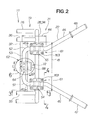
FIG. 2 is a top plan view of the handle device shown inFIG. 1 ; -
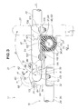
FIG. 3 is an enlarged cross-sectional view taken along line 3-3 ofFIG. 2 ; -
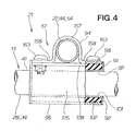
FIG. 4 is an enlarged cross-sectional view along line 4-4 ofFIG. 2 ; -
FIG. 5 is an exploded view of the handle device shown inFIG. 1 ; -
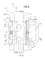
FIG. 6 is an enlargedview showing area 6 ofFIG. 2 ; -
FIG. 7 is a cross-sectional view taken along line 7-7 ofFIG. 6 ; -
FIG. 8A is a perspective view showing a fixed member of a clamp body shown inFIG. 7 ; -
FIG. 8B is a top plan view showing the fixed member; -
FIG. 8C is a cross-sectional view taken along line c-c ofFIG. 8B ; -
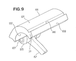
FIG. 9 is a perspective view showing a turning member ofFIG. 7 ; -
FIG. 10A is a front view showing the turning member ofFIG. 7 ; -
FIG. 10B is a side view of the turning member as seen in the direction of arrow b ofFIG. 10A ; -
FIG. 10C is a cross-sectional view taken along line c-c ofFIG. 10A ; -
FIG. 10D is a bottom view showing the turning member as seen in the direction of arrow d ofFIG. 10B ; -
FIG. 11A is a perspective view showing a movable pawl member of a restraining mechanism shown inFIG. 7 ; -
FIG. 11B is a view showing the movable pawl member ofFIG. 11A , as seen in the direction of arrow b ofFIG. 11A ; -
FIG. 11C is a cross-sectional view taken along line c-c ofFIG. 11B ; -
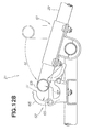
FIGS. 12A through 12C are views illustrating locking engaging/disengaging actions of the handle of the handle device according to the first embodiment; and -
FIG. 13 is an exploded perspective view of a crank mechanism according to a second embodiment of the present invention. - Reference is now made to
FIGS. 1 through 12 showing awork machine 11 according to a first embodiment. In thework machine 11 according to the present embodiment, a power generator is shown as an example. - The
work machine 11 comprises awork device 12 mounted on aframe 13, as shown inFIG. 1 . Thiswork device 12 includes a drive device (an engine) 15 and apower generation part 16. Ahandle 22 held on ahandle device 21 can be folded up. - Another possible example of the
work device 12, other than the power generator, is a pump device which deals with water or another fluid. - The
handle device 21 is attached to theframe 13 so that thehandle 22 can be folded up in the direction of arrow a1 as shown inFIGS. 1 and2 . The use position of thehandle 22 is shown by U, and the folded position of thehandle 22 is shown by S. When thehandle 22 is in the use position U, thework machine 11 is moved by grasping thehandle 22 by hand and pushing using thewheels 23. When the work machine is loaded onto an automobile, two people lift the machine by taking hold of thehandle 22 and theframe 13. - The
frame 13 is formed into a substantial square and is composed of abottom frame part 26, fourvertical frame parts 27 standing upright from thebottom frame part 26, and atop frame part 28 spanning as a continuation between thevertical frame parts 27. In other words, theframe 13 includes members, e.g., bottomcross base plates 31 and a topcross frame part 32 attached to a pipe frame. - The
wheels 23 and thecross base plates bottom frame part 26. On thecross base plates 31, theengine 15 and thepower generation part 16 are carried on thecross base plates - The
top frame part 28 is composed of a firstcross frame part 34 to which thehandle 22 is attached, first and second side frame parte 35, 36 continuing from the firstcross frame part 34, a secondcross frame part 37, and the topcross frame part 32 which is in proximity to the firstcross frame part 34. Thehandle 22 is attached to ahandle support part 41 of the firstcross frame part 34. - The
handle 22 is created by bending a steel pipe. Specifically, asupport part 44 supported on theframe 13 is plastically deformed into a U shape. Afirst arm part 45 is attached as a continuation to one end of thisU-shaped support part 44. Asecond arm part 46 is attached to the other end. Seen in a plan view, the first andsecond arm parts work machine 11 so as to widen outward. The first andsecond arm parts first grip part 47 and asecond grip part 48 at their respective ends. - Due to a 90° plastic deformation of a first
bent part 51 and a secondbent part 52, theU-shaped support part 44 has a handle engaging/disengaging part (a stopper part) 53 extending in the vehicle width direction, and first andsecond attachment parts - The handle engaging/disengaging
part 53 is engaged to and disengaged from aclamp mechanism 62 provided to the topcross frame part 32 when thehandle 22 is turned to the use position U. - The
first attachment part 54 and thesecond attachment part 55 are orthogonal to the firstcross frame part 34 of theframe 13, and are attached so as to be capable of turning relative to the first cross frame part 34 (in the direction of arrow a1). - When the
handle 22 is lifted up, causing thework machine 11 to be lifted up while thehandle 22 is in the use position U, force is created in the handle engaging/disengagingpart 53 as shown by arrow a2 and transmitted to the topcross frame part 32 of thework machine 11. - Next, the configuration of the
handle device 21 of thework machine 11 according to the first embodiment will be described based onFIGS. 1 through 7 . - The
handle device 21 has a structure in which ahandle 22 for transportation and movement, which has afirst grip part 47 and asecond grip part 48 extending to the rear of the vehicle body at the distal ends, is attached in a foldable manner to theframe 13 on which a power generator or anotherwork device 12 is carried. - The
handle device 21 comprises thefirst attachment part 54 and thesecond attachment part 55 which are attachment parts of thehandle 22 that intersect theframe 13, ahandle turning mechanism 61 for supporting theframe 13 to be capable of turning about a turning fulcrum P, and theclamp mechanism 62 for detachably fixing the handle engaging/disengagingpart 53 to theframe 13. The handle engaging/disengagingpart 53 continues from thefirst attachment part 54 and thesecond attachment part 55, continuing as extendingparts 45a, 46a extending into the frame 13 (in the direction of arrow a3 shown inFIGS. 2 and3 ). - The
clamp mechanism 62 includes aclamp body 64 for engaging and disengaging the handle engaging/disengagingpart 53, as shown inFIGS. 3 and12 . Theclamp body 64 has a fixedmember 74 fixed to theframe 13, and a turningmember 66 attached to the fixedmember 74 to be capable of turning in the direction of arrow a4 shown inFIG. 3 . P1 shown inFIG. 3 is the fulcrum of the turningmember 66. The turningmember 66 is constantly being urged by aspring 65 to a standby state (an open standby position W) so as to be open relative to the fixedmember 74. When the turningmember 66 closes against the force of thespring 65, a actuatingprotuberance 67 pushed by the handle engaging/disengagingpart 53 extends to the front of the work machine from the turningmember 66. A restrainingmechanism 72 automatically restrains thedistal end 71 of the turningmember 66 with a spring force when the actuatingprotuberance 67 is pushed further by the handle engaging/disengagingpart 53 and the turningmember 66 closes (to the closed position K). - In the inside surface of an
open end 78 of the fixedmember 74, acurved surface part 81 is formed in proximity to the handle engaging/disengagingpart 53, as shown inFIGS. 7 and8A through8C . Acurved surface part 82 in proximity to the handle engaging/disengagingpart 53 is formed in the inside surface of thedistal end 71 of the turningmember 66. The turningmember 66 is coupled with the fixedmember 74 by acoupling pin 84. Thecoupling pin 84 is a fulcrum of the turningmember 66 and is also a fulcrum of theclamp body 64. - The restraining
mechanism 72 comprises a fixedpawl 86 formed on thedistal end 71 of the turningmember 66, and amovable pawl member 88 turnably (in the direction of arrow a5) attached to the fixedmember 74 so as to engage with the fixedpawl 86 due to the spring force of areturn spring 87. - The
movable pawl member 88 interlocks with the fixedpawl 86 of the turningmember 66, and holds the turningmember 66 in the closed position K of theclamp body 64 against thespring 65 which turns the turningmember 66 in an opening direction. - The
spring 65 used in theclamp body 64 is a helical torsion spring, and the direction of the torsion load (the direction of arrow a6 inFIG. 5 ) is made to coincide with the direction in which theclamp body 64 opens (the direction of arrow a6). - Next, the
clamp mechanism 62 of the first embodiment will be described. - The
clamp mechanism 62 is composed of the previously described clamp body 64 (the fixedmember 74, the turningmember 66, thecoupling pin 84, and the spring 65), the actuatingprotuberance 67 formed on theclamp body 64, and the restrainingmechanism 72. K is the closed position of theclamp mechanism 62, the closed position of theclamp body 64, and also the closed position of the turningmember 66. - The length of the
clamp mechanism 62 is L as shown inFIG. 2 , and this length L is approximately 2.3 times the outside diameter of both thehandle 22 and the handle engaging/disengagingpart 53. The length L is also the length of the fixed member 74 (FIG. 8B ). - The fixed
member 74 has a basemain body 105 fixed to the topcross frame part 32 of theframe 13 as shown inFIGS. 7 and8A . In the basemain body 105, a pressure-bearinggroove 106 is formed into a shape that fits over the handle engaging/disengagingpart 53, and is also formed running along the handle engaging/disengagingpart 53. - In the longitudinal (widthwise) center of the
pressure bearing groove 106, anaccommodating part 107 is formed to a depth which accommodates the actuatingprotuberance 67, and near theaccommodating part 107 an engagingconcavity 108 is formed into a shape which engages the end of thespring 65. - In both dies of the pressure-bearing
groove 106 in the width direction, holes 111 are formed through which fastening bolts 109 (FIG. 5 ) are inserted. The longitudinal direction (the width direction) of the pressure-bearinggroove 106 is made to coincide with the longitudinal direction (the width direction) of the handle engaging/disengagingpart 53. - The base
main body 105 has a firstbase hinge part 113 formed in the side of a first dividedend 112, and a secondbase hinge part 115 formed in the side of a second divided end 114 (the open end 78). - The top surface of the second divided
end 114 substantially coincides with a line E passing through the center of the radius r1 of the handle engaging/disengagingpart 53 as shown inFIG. 7 . The depth of the pressure-bearinggroove 106 substantially coincides with the external peripheral radius r1 of the handle engaging/disengagingpart 53. The peripheral length of the pressure-bearinggroove 106 is approximately 50% of the external peripheral length of the handle engaging/disengagingpart 53. The turningmember 66 is coupled with the firstbase hinge part 113 by a coupling pin (including a retaining ring). - The turning
member 66 has apressing groove 122 formed in a turningmain body 121 so as to face the pressure-bearinggroove 106, as shown inFIGS. 7 ,9 , and10B . Thepressing groove 122 is formed into a curved shape along the longitudinal direction of the handle engaging/disengagingpart 53 so that the handle engaging/disengagingpart 53 fits therein. - In the longitudinal center of the turning
main body 121, aconcave part 123 is formed for engaging the end of thespring 65. A thirddivided end 125 and a fourth divided end (a distal end 71) are formed in the turningmain body 121. The thirddivided end 125 is formed so that afirst hinge part 127 is coupled with the firstbase hinge part 113 by thecoupling pin 84. - A
push surface 128 is formed as a continuation of the fourth divided end (the distal end 71) so as to push on themovable pawl member 88. The fixedpawl 86 is formed as a continuation of thepush surface 128. The actuatingprotuberance 67 is formed as a continuation of the thirddivided end 125. - The actuating
protuberance 67 extends toward the handle engaging/disengagingpart 53 in a state in which the clamp body 64 (the turning member 66) of theclamp mechanism 62 has been opened (the open standby position W). When the actuatingprotuberance 67 is pushed by the handle engaging/disengagingpart 53, the actuatingprotuberance 67 turns and pushes on themovable pawl member 88 via thepush surface 128 provided to the fourth divided end (the distal end 71). - A
movable pawl 132 of themovable pawl member 88 is formed on one end of amain body 131 as shown inFIGS. 11A and 11C . Acontact surface 133 is formed as a continuation of themovable pawl 132. In the other end side of themain body 131, an operatingpart 134 is formed so that it can be pushed by hand. - A
second hinge part 135, which is formed in the center of themain body 131 between themovable pawl 132 and theoperating part 134, is coupled with the secondbase hinge part 115 by acoupling pint 136. Aconcave part 137, which engages one end of thereturn spring 87, is formed in proximity to thesecond hinge part 135. The other end of thereturn spring 87 is in contact with the basemain body 105 of the fixedmember 74. Thereturn spring 87 is a helical torsion spring. - Next, the action of the
handle device 21 of thework machine 11 according to the first embodiment will be described. - With this
handle device 21, when thehandle 22 is turned from the folded position S to the use position U as shown by arrow b1 inFIG. 1 , the handle engaging/disengaging part (the stopper part) 53 of thehandle 22 is automatically locked by theclamp mechanism 62. - Specifically, when the
handle 22 is folded up as shown inFIG. 12A , theclamp mechanism 62 is opened and kept in the open standby position W by thespring 65. To bring thehandle 22 to the use state, thehandle 22 turns in the direction shown by arrow b1. - The handle engaging/disengaging
part 53 then comes in contact with the actuatingprotuberance 67 of the turningmember 66 of theclamp mechanism 62, as shown inFIG. 12B . - When the
handle 22 is turned further, the handle engaging/disengagingpart 53 pushes on theactuating protuberance 67, and the actuatingprotuberance 67 therefore begins the turn about a hinge (the firstbase hinge part 113 and the first hinge part 127) against thespring 65 as shown by arrow b3 inFIG. 12C . At the same time, the turningmember 66 also begins to turn in the direction shown by arrow b3. - Furthermore, when the
handle 22 is turned, thepush surface 128 connected to thedistal end 71 of the turningmember 66 pushes on thecontact surface 133 of themovable pawl member 88, and themovable pawl member 88 therefore begins to turn about a hinge (the secondbase hinge part 115 and the second hinge part 135) in the direction shown by arrow b4 against thereturn spring 87, as shown by the double-dashed lines. As a result, interference between themovable pawl member 88 and thedistal end 71 of the turningmember 66 can be prevented. - When the actuating
protuberance 67 is then pushed by the handle engaging/disengagingpart 53 and the actuatingprotuberance 67 and the turning member 66 (the turning main body 121) turn further, the actuatingprotuberance 67 moves into theaccommodating part 107 of the fixedmember 74. Thedistal end 71 of the turningmember 66 then comes in contact with or draws near to the second divided end 114 (the open end 78) of the fixed member 74 (the base main body 105). - The turning
member 66 reaches the closed position K as shown inFIG. 7 and thepush surface 128 therefore separates from thecontact surface 133. Themovable pawl member 88 turns in the direction of arrow b5 shown inFIG. 12C , and the fixedpawl 86 of the turningmember 66 engages with themovable pawl 132. - Therefore the handle engaging/disengaging
part 53 is automatically fixed (locked) to theframe 13 in the use position U. - Conversely, when the
handle 22 is folded up, when the operatingpart 134 of themovable pawl member 88 of theclamp mechanism 62 is pushed against thereturn spring 87 as shown by arrow b6 inFIG. 7 , themovable pawl member 88 turns as shown by the double-dashed line, and themovable pawl 132 separates from the fixedpawl 86. - When the
handle 22 is then turned to the folded position S (FIG. 1 ), the turningmember 66 of theclamp mechanism 62 turns as shown by arrow b7 due to thespring 65, and opens as shown by the double-dashed lines (the open standby position W). Specifically, the turningmember 66 of theclamp body 64 turns in synchronization with the movement of the handle engaging/disengagingpart 53, and is thereafter held in the open standby position W by thespring 65. - Thus, since the
handle device 21 according to the first embodiment comprises theclamp mechanism 62, it is easy to fix thehandle 22 in the use position U. Furthermore, since theclamp mechanism 62 is composed of theclamp body 64, the actuatingprotuberance 67, and the restrainingmechanism 72, the structure is simplified. - Since a long distance is integrally set from the fulcrum (the handle turning mechanism 61) of the
handle 22 to the handle engaging/disengaging part (the stopper part) 53, the load imposed on the handle engaging/disengagingpart 53 can be lessened without compromising the simplicity of the structure. - Next, the handle device of the work machine according to a second embodiment will be described based on
FIG. 13 . Components similar to those of the first embodiment are denoted by the same symbols and are not described. - A
handle device 21B according to the second embodiment comprises aclamp mechanism 62B. Theclamp mechanism 62B is composed of aclamp body 64B (afixed member 74B, a turningmember 66B, and a spring 65 (FIG. 7 )), aactuating protuberance 67B formed on theclamp body 64B, and arestraining mechanism 72B. - The
clamp mechanism 62B has a width LB that is shorter than the width L of theclamp mechanism 62 of the first embodiment. The width LB of theclamp mechanism 62B is about 30% of the length of theclamp mechanism 62 according to the first embodiment. - The
handle device 21B according to the second embodiment exhibits the same actions and effects as thehandle device 21 according to the first embodiment. - Since the
handle device 21B according to the second embodiment is shorter in width than theclamp mechanism 62 of the first embodiment, the weight of theclamp mechanism 62B can be reduced, and the weight of thework machine 11 can be effectively reduced. - The handle device of the work machine according to the present invention is suitable for mobile power generators and pumps.
- A work machine handle device having a foldable handle (22) is disclosed. As the handle (22) is to be changed from a folded-up state to a use state, the handle (22) is turned about a frame (13) as a turning fulcrum. An actuating protuberance (67) provided integrally to a turning member (66) of a clamp body (64) is pushed by a handle engaging/disengaging part (53) provided to a front end of the handle (22), and the turning member (66) is caused to turn. The handle engaging/disengaging part (53) is held from either side and automatically restrained by a clamp mechanism (62). When the handle (22) is changed from the use state to the folded-up state, a restraining mechanism (72) is operated to release the engagement between the restraining mechanism and a distal end (71) of the turning member (66). The turning member (66) is turned by a return force of a spring (65) provided to the clamp body (64), the handle engaging/disengaging part (53) ceases to be restrained, and the handle (22) can be folded up.
Claims (4)
- A handle device (21) of a work machine (11), comprising:a frame (13) for carrying a work device (12);a transportation/movement handle (22) attached in a foldable manner to the frame (13), extending outwardly of the frame, and having left and right grip parts (47, 48) at distal ends;a handle turning mechanism (61) for supporting attachment parts (54, 55) of the handle (22) that intersect the frame (13) in such a manner as to be capable of turning about the frame (13) as a turning fulcrum; anda clamp mechanism (62) for detachably fixing a handle engaging/disengaging part (53) to the frame (13), the handle engaging/disengaging part continuing from the attachment parts (54, 55), extending forwardly of the frame (13) and positioned on a side opposite the grip parts (47, 48),wherein the clamp mechanism (62) comprises:a clamp body (64) for clamping the handle engaging/disengaging part (53) by closing;a spring (65) of the clamp body (64), for holding the clamp body (64) in an open standby state;a actuating protuberance (67) which, when closed against a spring force of the spring (65), extends from a turning member (66) of the clamp body (64) toward the handle engaging/disengaging part (53) so as to contact and be pushed by the handle engaging/disengaging part (53); anda restraining mechanism (72) for automatically restraining a distal end (71) of the clamp body by a spring force when the clamp body (64) is closed due to the actuating protuberance (67) being pushed further and brought nearer to the frame (13).
- The handle device of claim 1, wherein the clamp body (64) is comprised of a fixed member (74) fixed to the frame (13) and the turning member (66) turnably attached to the fixed member and provided with the actuating protuberance (67), the fixed member (74) has an open end (78) with an inside surface (81) being curved and in proximity to the handle engaging/disengaging part (53), and the turning member (66) has a distal end (71) with an inside surface (82) being curved and in proximity to the handle engaging/disengaging part.
- The handle device of claim 1, wherein the clamp body (64) is comprised of a fixed member (74) fixed to the frame (13) and the turning member (66) turnably attached to the fixed member and provided with the actuating protuberance (67), and the restraining mechanism (72) is comprised of a fixed pawl (86) formed on a distal end (71) of the turning member (66) and a movable pawl member (88) turnably attached to the fixed member (74) so as to engage the fixed pawl by a spring force of a return spring (87).
- The handle device of claim 1, wherein the spring (65) is a helical torsion spring, and a direction of a torsion load coincides with a direction in which the clamp body (64) opens.
Applications Claiming Priority (1)
| Application Number | Priority Date | Filing Date | Title |
|---|---|---|---|
| JP2010141479A JP5439291B2 (en) | 2010-06-22 | 2010-06-22 | Handle device for work equipment |
Publications (2)
| Publication Number | Publication Date |
|---|---|
| EP2400130A1 true EP2400130A1 (en) | 2011-12-28 |
| EP2400130B1 EP2400130B1 (en) | 2012-11-14 |
Family
ID=44774259
Family Applications (1)
| Application Number | Title | Priority Date | Filing Date |
|---|---|---|---|
| EP11170856A Not-in-force EP2400130B1 (en) | 2010-06-22 | 2011-06-22 | Handle device of work machine |
Country Status (5)
| Country | Link |
|---|---|
| US (1) | US8695167B2 (en) |
| EP (1) | EP2400130B1 (en) |
| JP (1) | JP5439291B2 (en) |
| CN (1) | CN102310879B (en) |
| CA (1) | CA2743876C (en) |
Families Citing this family (20)
| Publication number | Priority date | Publication date | Assignee | Title |
|---|---|---|---|---|
| JP5514644B2 (en) * | 2010-06-22 | 2014-06-04 | 本田技研工業株式会社 | Handle device for work equipment |
| CN104564939B (en) * | 2013-10-23 | 2017-02-22 | 南京德朔实业有限公司 | Locking device, telescopic rod applying locking device and mower |
| CN103730875B (en) * | 2013-12-25 | 2016-04-27 | 江东金具设备有限公司 | A kind of conductor spacer self-locking wire clamp |
| CN105886189A (en) * | 2016-06-30 | 2016-08-24 | 成都世唯科技有限公司 | Koji block placing shelf |
| CN108612992B (en) * | 2016-12-13 | 2020-05-19 | 力山工业股份有限公司 | foldable stand |
| US11230336B2 (en) * | 2018-03-23 | 2022-01-25 | Neutron Holdings, Inc. | Device mounting system for a vehicle |
| CN109356716B (en) * | 2018-10-29 | 2020-11-20 | 江苏康宇发电设备有限公司 | Diesel generating set convenient to move |
| CN111301498A (en) * | 2019-12-10 | 2020-06-19 | 苏州市意润达智能科技有限公司 | Volume variable handcart |
| US12226007B2 (en) * | 2020-05-06 | 2025-02-18 | Paul L. Williamson | Detachable shopping cart handle device |
| US12334577B2 (en) | 2021-05-10 | 2025-06-17 | Milwaukee Electric Tool Corporation | Mobile power supply |
| CN119968139A (en) * | 2022-08-31 | 2025-05-09 | W.L.戈尔及同仁股份有限公司 | Convertible package system and method |
| US20240343290A1 (en) * | 2023-01-27 | 2024-10-17 | Michael E Miller | Utility cart wiht a handle adaptable for pulling and pushing |
| USD1085010S1 (en) | 2023-10-11 | 2025-07-22 | Northern Tool & Equipment Company, Inc. | Generator assembly |
| USD1085006S1 (en) | 2023-10-11 | 2025-07-22 | Northern Tool & Equipment Company, Inc. | Generator assembly |
| USD1085008S1 (en) | 2023-10-11 | 2025-07-22 | Northern Tool & Equipment Company, Inc. | Generator assembly |
| USD1085007S1 (en) | 2023-10-11 | 2025-07-22 | Northern Tool & Equipment Company, Inc. | Generator assembly |
| USD1085011S1 (en) | 2023-10-11 | 2025-07-22 | Northern Tool & Equipment Company, Inc. | Generator assembly |
| USD1085009S1 (en) | 2023-10-11 | 2025-07-22 | Northern Tool & Equipment Company, Inc. | Generator assembly |
| USD1085012S1 (en) | 2023-10-11 | 2025-07-22 | Northern Tool & Equipment Company, Inc. | Generator assembly |
| CN117307661B (en) * | 2023-11-28 | 2024-02-09 | 山东禾田动力科技有限公司 | Damping device for range extender |
Citations (4)
| Publication number | Priority date | Publication date | Assignee | Title |
|---|---|---|---|---|
| DE102004028584A1 (en) * | 2004-06-15 | 2005-12-29 | Murrplastik Systemtechnik Gmbh | Clip for hoses, cables or pipes has base plate which is screwed to wall and carries integral jaws which fit around pipe and are connected at center by film hinge which allows them to swivel as pipe is inserted |
| JP2007115457A (en) | 2005-10-19 | 2007-05-10 | Sanyo Kiki Co Ltd | Floodlight frame |
| JP4226404B2 (en) | 2003-07-10 | 2009-02-18 | 本田技研工業株式会社 | Handle device for work equipment |
| EP2138686A1 (en) * | 2008-06-27 | 2009-12-30 | Honda Motor Co., Ltd. | Engine generator |
Family Cites Families (18)
| Publication number | Priority date | Publication date | Assignee | Title |
|---|---|---|---|---|
| US3167346A (en) * | 1963-04-24 | 1965-01-26 | Marvin O Miller | Quick acting hook |
| GB1322771A (en) | 1970-07-23 | 1973-07-11 | Maxview Aerials Ltd | Clamps for example for aeriels |
| US4708357A (en) * | 1986-03-31 | 1987-11-24 | Gerard Berkowitz | Adaptor handle |
| US5590440A (en) | 1995-03-23 | 1997-01-07 | Bradley Corporation | Grab bar assembly |
| US6742995B1 (en) * | 2000-03-08 | 2004-06-01 | Devilbiss Air Power Company | Air compressor assembly |
| US6749214B2 (en) * | 2002-05-30 | 2004-06-15 | Shanq-Ching Shieh | Locking device for a foldable golf cart |
| US6715785B2 (en) * | 2002-05-30 | 2004-04-06 | Shanq-Ching Shieh | Locking device for a foldable golf cart |
| WO2005005225A1 (en) * | 2003-07-10 | 2005-01-20 | Honda Motor Co., Ltd. | Engine-driven working machine |
| US20070163566A1 (en) * | 2006-01-14 | 2007-07-19 | Adam Johnson | Adjustable handle for a concrete saw |
| US7849564B2 (en) | 2006-04-27 | 2010-12-14 | Stander Inc. | Pivoting support handle |
| CN101147452B (en) * | 2006-09-21 | 2011-09-07 | 苏州宝时得电动工具有限公司 | Mower |
| US8113315B2 (en) * | 2008-04-15 | 2012-02-14 | Cnh America Llc | Rear deck service ladder and handle assembly for combines |
| US20100072717A1 (en) * | 2008-05-06 | 2010-03-25 | Graco Minnesota, Inc. | Striper with adjustable handle |
| JP4918525B2 (en) * | 2008-06-18 | 2012-04-18 | 本田技研工業株式会社 | Portable generator |
| JP4977656B2 (en) | 2008-06-27 | 2012-07-18 | 本田技研工業株式会社 | Engine driven generator |
| JP4977655B2 (en) * | 2008-06-27 | 2012-07-18 | 本田技研工業株式会社 | Engine driven generator |
| JP5297890B2 (en) * | 2008-12-03 | 2013-09-25 | 本田技研工業株式会社 | Pipe handle holding mechanism |
| US8635744B2 (en) * | 2010-08-20 | 2014-01-28 | Briggs & Stratton Corporation | Foldable handle retainer |
-
2010
- 2010-06-22 JP JP2010141479A patent/JP5439291B2/en not_active Expired - Fee Related
-
2011
- 2011-06-21 CA CA2743876A patent/CA2743876C/en not_active Expired - Fee Related
- 2011-06-21 CN CN2011101675763A patent/CN102310879B/en not_active Expired - Fee Related
- 2011-06-22 US US13/165,994 patent/US8695167B2/en active Active
- 2011-06-22 EP EP11170856A patent/EP2400130B1/en not_active Not-in-force
Patent Citations (4)
| Publication number | Priority date | Publication date | Assignee | Title |
|---|---|---|---|---|
| JP4226404B2 (en) | 2003-07-10 | 2009-02-18 | 本田技研工業株式会社 | Handle device for work equipment |
| DE102004028584A1 (en) * | 2004-06-15 | 2005-12-29 | Murrplastik Systemtechnik Gmbh | Clip for hoses, cables or pipes has base plate which is screwed to wall and carries integral jaws which fit around pipe and are connected at center by film hinge which allows them to swivel as pipe is inserted |
| JP2007115457A (en) | 2005-10-19 | 2007-05-10 | Sanyo Kiki Co Ltd | Floodlight frame |
| EP2138686A1 (en) * | 2008-06-27 | 2009-12-30 | Honda Motor Co., Ltd. | Engine generator |
Also Published As
| Publication number | Publication date |
|---|---|
| CN102310879A (en) | 2012-01-11 |
| CN102310879B (en) | 2012-12-12 |
| JP5439291B2 (en) | 2014-03-12 |
| CA2743876C (en) | 2014-02-25 |
| CA2743876A1 (en) | 2011-12-22 |
| JP2012006420A (en) | 2012-01-12 |
| US8695167B2 (en) | 2014-04-15 |
| EP2400130B1 (en) | 2012-11-14 |
| US20110308045A1 (en) | 2011-12-22 |
Similar Documents
| Publication | Publication Date | Title |
|---|---|---|
| EP2400130B1 (en) | Handle device of work machine | |
| EP2400129B1 (en) | Handle device of work machine | |
| KR101028876B1 (en) | Auto-lock mechanism | |
| US12264449B2 (en) | Coupler | |
| EP1407923A1 (en) | Inertia lock device and foldable sheet | |
| EP4168287B1 (en) | Carrier frame | |
| US7108305B2 (en) | Automotive seat assembly having a rear latch lockout and spring assist | |
| JP5359564B2 (en) | Locking device | |
| JP2012035788A (en) | Tire holding mechanism of carrier for bicycle | |
| JP5437413B2 (en) | Tube gripping fitting and tube gripping device | |
| CN212529928U (en) | Steering locking mechanism and scooter | |
| JP5121049B2 (en) | In-vehicle stretcher | |
| JP4082148B2 (en) | Detaching device for vehicle seat | |
| JP7189596B2 (en) | Lifter for step-climbing and transportation equipment provided with the same | |
| JP4530257B2 (en) | Buckle for holding battery cover of battery powered vehicle | |
| EP3581462A1 (en) | Roll container | |
| JP4128592B2 (en) | Container holder device | |
| WO2024255984A1 (en) | Folding bicycle frame and methods for folding and unfolding said folding bicycle frame | |
| FR2886216A1 (en) | DEVICE FOR CONVEYING AN ERGONOMIC COUPLING MECHANISM | |
| JPH08253181A (en) | Bicycle seat turning device | |
| JP4326405B2 (en) | Vehicle seat | |
| JP2018024347A (en) | Bicycle carrier device mounted on vehicle | |
| JP2017171019A (en) | Removable stand | |
| JP6240024B2 (en) | Locking device | |
| JP3872777B6 (en) | Folding tricycle |
Legal Events
| Date | Code | Title | Description |
|---|---|---|---|
| 17P | Request for examination filed |
Effective date: 20110622 |
|
| AK | Designated contracting states |
Kind code of ref document: A1 Designated state(s): AL AT BE BG CH CY CZ DE DK EE ES FI FR GB GR HR HU IE IS IT LI LT LU LV MC MK MT NL NO PL PT RO RS SE SI SK SM TR |
|
| AX | Request for extension of the european patent |
Extension state: BA ME |
|
| PUAI | Public reference made under article 153(3) epc to a published international application that has entered the european phase |
Free format text: ORIGINAL CODE: 0009012 |
|
| GRAP | Despatch of communication of intention to grant a patent |
Free format text: ORIGINAL CODE: EPIDOSNIGR1 |
|
| GRAS | Grant fee paid |
Free format text: ORIGINAL CODE: EPIDOSNIGR3 |
|
| GRAA | (expected) grant |
Free format text: ORIGINAL CODE: 0009210 |
|
| AK | Designated contracting states |
Kind code of ref document: B1 Designated state(s): AL AT BE BG CH CY CZ DE DK EE ES FI FR GB GR HR HU IE IS IT LI LT LU LV MC MK MT NL NO PL PT RO RS SE SI SK SM TR |
|
| REG | Reference to a national code |
Ref country code: GB Ref legal event code: FG4D |
|
| REG | Reference to a national code |
Ref country code: CH Ref legal event code: EP Ref country code: AT Ref legal event code: REF Ref document number: 584129 Country of ref document: AT Kind code of ref document: T Effective date: 20121115 |
|
| REG | Reference to a national code |
Ref country code: IE Ref legal event code: FG4D |
|
| REG | Reference to a national code |
Ref country code: DE Ref legal event code: R096 Ref document number: 602011000447 Country of ref document: DE Effective date: 20130103 |
|
| REG | Reference to a national code |
Ref country code: NL Ref legal event code: VDEP Effective date: 20121114 |
|
| REG | Reference to a national code |
Ref country code: AT Ref legal event code: MK05 Ref document number: 584129 Country of ref document: AT Kind code of ref document: T Effective date: 20121114 |
|
| REG | Reference to a national code |
Ref country code: LT Ref legal event code: MG4D |
|
| PG25 | Lapsed in a contracting state [announced via postgrant information from national office to epo] |
Ref country code: NO Free format text: LAPSE BECAUSE OF FAILURE TO SUBMIT A TRANSLATION OF THE DESCRIPTION OR TO PAY THE FEE WITHIN THE PRESCRIBED TIME-LIMIT Effective date: 20130214 Ref country code: FI Free format text: LAPSE BECAUSE OF FAILURE TO SUBMIT A TRANSLATION OF THE DESCRIPTION OR TO PAY THE FEE WITHIN THE PRESCRIBED TIME-LIMIT Effective date: 20121114 Ref country code: SE Free format text: LAPSE BECAUSE OF FAILURE TO SUBMIT A TRANSLATION OF THE DESCRIPTION OR TO PAY THE FEE WITHIN THE PRESCRIBED TIME-LIMIT Effective date: 20121114 Ref country code: LT Free format text: LAPSE BECAUSE OF FAILURE TO SUBMIT A TRANSLATION OF THE DESCRIPTION OR TO PAY THE FEE WITHIN THE PRESCRIBED TIME-LIMIT Effective date: 20121114 Ref country code: HR Free format text: LAPSE BECAUSE OF FAILURE TO SUBMIT A TRANSLATION OF THE DESCRIPTION OR TO PAY THE FEE WITHIN THE PRESCRIBED TIME-LIMIT Effective date: 20121114 Ref country code: ES Free format text: LAPSE BECAUSE OF FAILURE TO SUBMIT A TRANSLATION OF THE DESCRIPTION OR TO PAY THE FEE WITHIN THE PRESCRIBED TIME-LIMIT Effective date: 20130225 |
|
| PG25 | Lapsed in a contracting state [announced via postgrant information from national office to epo] |
Ref country code: SI Free format text: LAPSE BECAUSE OF FAILURE TO SUBMIT A TRANSLATION OF THE DESCRIPTION OR TO PAY THE FEE WITHIN THE PRESCRIBED TIME-LIMIT Effective date: 20121114 Ref country code: PT Free format text: LAPSE BECAUSE OF FAILURE TO SUBMIT A TRANSLATION OF THE DESCRIPTION OR TO PAY THE FEE WITHIN THE PRESCRIBED TIME-LIMIT Effective date: 20130314 Ref country code: GR Free format text: LAPSE BECAUSE OF FAILURE TO SUBMIT A TRANSLATION OF THE DESCRIPTION OR TO PAY THE FEE WITHIN THE PRESCRIBED TIME-LIMIT Effective date: 20130215 Ref country code: PL Free format text: LAPSE BECAUSE OF FAILURE TO SUBMIT A TRANSLATION OF THE DESCRIPTION OR TO PAY THE FEE WITHIN THE PRESCRIBED TIME-LIMIT Effective date: 20121114 Ref country code: LV Free format text: LAPSE BECAUSE OF FAILURE TO SUBMIT A TRANSLATION OF THE DESCRIPTION OR TO PAY THE FEE WITHIN THE PRESCRIBED TIME-LIMIT Effective date: 20121114 Ref country code: BE Free format text: LAPSE BECAUSE OF FAILURE TO SUBMIT A TRANSLATION OF THE DESCRIPTION OR TO PAY THE FEE WITHIN THE PRESCRIBED TIME-LIMIT Effective date: 20121114 |
|
| PG25 | Lapsed in a contracting state [announced via postgrant information from national office to epo] |
Ref country code: AT Free format text: LAPSE BECAUSE OF FAILURE TO SUBMIT A TRANSLATION OF THE DESCRIPTION OR TO PAY THE FEE WITHIN THE PRESCRIBED TIME-LIMIT Effective date: 20121114 |
|
| PG25 | Lapsed in a contracting state [announced via postgrant information from national office to epo] |
Ref country code: CZ Free format text: LAPSE BECAUSE OF FAILURE TO SUBMIT A TRANSLATION OF THE DESCRIPTION OR TO PAY THE FEE WITHIN THE PRESCRIBED TIME-LIMIT Effective date: 20121114 Ref country code: EE Free format text: LAPSE BECAUSE OF FAILURE TO SUBMIT A TRANSLATION OF THE DESCRIPTION OR TO PAY THE FEE WITHIN THE PRESCRIBED TIME-LIMIT Effective date: 20121114 Ref country code: DK Free format text: LAPSE BECAUSE OF FAILURE TO SUBMIT A TRANSLATION OF THE DESCRIPTION OR TO PAY THE FEE WITHIN THE PRESCRIBED TIME-LIMIT Effective date: 20121114 Ref country code: RS Free format text: LAPSE BECAUSE OF FAILURE TO SUBMIT A TRANSLATION OF THE DESCRIPTION OR TO PAY THE FEE WITHIN THE PRESCRIBED TIME-LIMIT Effective date: 20121114 Ref country code: SK Free format text: LAPSE BECAUSE OF FAILURE TO SUBMIT A TRANSLATION OF THE DESCRIPTION OR TO PAY THE FEE WITHIN THE PRESCRIBED TIME-LIMIT Effective date: 20121114 Ref country code: BG Free format text: LAPSE BECAUSE OF FAILURE TO SUBMIT A TRANSLATION OF THE DESCRIPTION OR TO PAY THE FEE WITHIN THE PRESCRIBED TIME-LIMIT Effective date: 20130214 |
|
| PG25 | Lapsed in a contracting state [announced via postgrant information from national office to epo] |
Ref country code: RO Free format text: LAPSE BECAUSE OF FAILURE TO SUBMIT A TRANSLATION OF THE DESCRIPTION OR TO PAY THE FEE WITHIN THE PRESCRIBED TIME-LIMIT Effective date: 20121114 Ref country code: NL Free format text: LAPSE BECAUSE OF FAILURE TO SUBMIT A TRANSLATION OF THE DESCRIPTION OR TO PAY THE FEE WITHIN THE PRESCRIBED TIME-LIMIT Effective date: 20121114 |
|
| PLBE | No opposition filed within time limit |
Free format text: ORIGINAL CODE: 0009261 |
|
| STAA | Information on the status of an ep patent application or granted ep patent |
Free format text: STATUS: NO OPPOSITION FILED WITHIN TIME LIMIT |
|
| 26N | No opposition filed |
Effective date: 20130815 |
|
| PG25 | Lapsed in a contracting state [announced via postgrant information from national office to epo] |
Ref country code: CY Free format text: LAPSE BECAUSE OF FAILURE TO SUBMIT A TRANSLATION OF THE DESCRIPTION OR TO PAY THE FEE WITHIN THE PRESCRIBED TIME-LIMIT Effective date: 20121114 |
|
| REG | Reference to a national code |
Ref country code: DE Ref legal event code: R097 Ref document number: 602011000447 Country of ref document: DE Effective date: 20130815 |
|
| PG25 | Lapsed in a contracting state [announced via postgrant information from national office to epo] |
Ref country code: MC Free format text: LAPSE BECAUSE OF FAILURE TO SUBMIT A TRANSLATION OF THE DESCRIPTION OR TO PAY THE FEE WITHIN THE PRESCRIBED TIME-LIMIT Effective date: 20121114 |
|
| REG | Reference to a national code |
Ref country code: IE Ref legal event code: MM4A |
|
| PG25 | Lapsed in a contracting state [announced via postgrant information from national office to epo] |
Ref country code: IE Free format text: LAPSE BECAUSE OF NON-PAYMENT OF DUE FEES Effective date: 20130622 |
|
| REG | Reference to a national code |
Ref country code: CH Ref legal event code: PL |
|
| PG25 | Lapsed in a contracting state [announced via postgrant information from national office to epo] |
Ref country code: MT Free format text: LAPSE BECAUSE OF FAILURE TO SUBMIT A TRANSLATION OF THE DESCRIPTION OR TO PAY THE FEE WITHIN THE PRESCRIBED TIME-LIMIT Effective date: 20121114 |
|
| PG25 | Lapsed in a contracting state [announced via postgrant information from national office to epo] |
Ref country code: LI Free format text: LAPSE BECAUSE OF NON-PAYMENT OF DUE FEES Effective date: 20140630 Ref country code: CH Free format text: LAPSE BECAUSE OF NON-PAYMENT OF DUE FEES Effective date: 20140630 |
|
| PG25 | Lapsed in a contracting state [announced via postgrant information from national office to epo] |
Ref country code: SM Free format text: LAPSE BECAUSE OF FAILURE TO SUBMIT A TRANSLATION OF THE DESCRIPTION OR TO PAY THE FEE WITHIN THE PRESCRIBED TIME-LIMIT Effective date: 20121114 |
|
| PG25 | Lapsed in a contracting state [announced via postgrant information from national office to epo] |
Ref country code: TR Free format text: LAPSE BECAUSE OF FAILURE TO SUBMIT A TRANSLATION OF THE DESCRIPTION OR TO PAY THE FEE WITHIN THE PRESCRIBED TIME-LIMIT Effective date: 20121114 |
|
| PG25 | Lapsed in a contracting state [announced via postgrant information from national office to epo] |
Ref country code: LU Free format text: LAPSE BECAUSE OF NON-PAYMENT OF DUE FEES Effective date: 20130622 Ref country code: HU Free format text: LAPSE BECAUSE OF FAILURE TO SUBMIT A TRANSLATION OF THE DESCRIPTION OR TO PAY THE FEE WITHIN THE PRESCRIBED TIME-LIMIT; INVALID AB INITIO Effective date: 20110622 Ref country code: MK Free format text: LAPSE BECAUSE OF FAILURE TO SUBMIT A TRANSLATION OF THE DESCRIPTION OR TO PAY THE FEE WITHIN THE PRESCRIBED TIME-LIMIT Effective date: 20121114 |
|
| REG | Reference to a national code |
Ref country code: FR Ref legal event code: PLFP Year of fee payment: 6 |
|
| PG25 | Lapsed in a contracting state [announced via postgrant information from national office to epo] |
Ref country code: IS Free format text: LAPSE BECAUSE OF FAILURE TO SUBMIT A TRANSLATION OF THE DESCRIPTION OR TO PAY THE FEE WITHIN THE PRESCRIBED TIME-LIMIT Effective date: 20121114 |
|
| REG | Reference to a national code |
Ref country code: FR Ref legal event code: PLFP Year of fee payment: 7 |
|
| REG | Reference to a national code |
Ref country code: FR Ref legal event code: PLFP Year of fee payment: 8 |
|
| PG25 | Lapsed in a contracting state [announced via postgrant information from national office to epo] |
Ref country code: AL Free format text: LAPSE BECAUSE OF FAILURE TO SUBMIT A TRANSLATION OF THE DESCRIPTION OR TO PAY THE FEE WITHIN THE PRESCRIBED TIME-LIMIT Effective date: 20121114 |
|
| PGFP | Annual fee paid to national office [announced via postgrant information from national office to epo] |
Ref country code: GB Payment date: 20200610 Year of fee payment: 10 Ref country code: IT Payment date: 20200512 Year of fee payment: 10 |
|
| PGFP | Annual fee paid to national office [announced via postgrant information from national office to epo] |
Ref country code: DE Payment date: 20210525 Year of fee payment: 11 Ref country code: FR Payment date: 20210514 Year of fee payment: 11 |
|
| GBPC | Gb: european patent ceased through non-payment of renewal fee |
Effective date: 20210622 |
|
| PG25 | Lapsed in a contracting state [announced via postgrant information from national office to epo] |
Ref country code: GB Free format text: LAPSE BECAUSE OF NON-PAYMENT OF DUE FEES Effective date: 20210622 |
|
| PG25 | Lapsed in a contracting state [announced via postgrant information from national office to epo] |
Ref country code: IT Free format text: LAPSE BECAUSE OF NON-PAYMENT OF DUE FEES Effective date: 20210622 |
|
| REG | Reference to a national code |
Ref country code: DE Ref legal event code: R119 Ref document number: 602011000447 Country of ref document: DE |
|
| PG25 | Lapsed in a contracting state [announced via postgrant information from national office to epo] |
Ref country code: FR Free format text: LAPSE BECAUSE OF NON-PAYMENT OF DUE FEES Effective date: 20220630 |
|
| PG25 | Lapsed in a contracting state [announced via postgrant information from national office to epo] |
Ref country code: DE Free format text: LAPSE BECAUSE OF NON-PAYMENT OF DUE FEES Effective date: 20230103 |