EP2399628A1 - Auto-injecteur - Google Patents
Auto-injecteur Download PDFInfo
- Publication number
- EP2399628A1 EP2399628A1 EP10167480A EP10167480A EP2399628A1 EP 2399628 A1 EP2399628 A1 EP 2399628A1 EP 10167480 A EP10167480 A EP 10167480A EP 10167480 A EP10167480 A EP 10167480A EP 2399628 A1 EP2399628 A1 EP 2399628A1
- Authority
- EP
- European Patent Office
- Prior art keywords
- syringe
- housing
- proximal
- auto
- injector
- Prior art date
- Legal status (The legal status is an assumption and is not a legal conclusion. Google has not performed a legal analysis and makes no representation as to the accuracy of the status listed.)
- Ceased
Links
Images


Classifications
-
- A—HUMAN NECESSITIES
- A61—MEDICAL OR VETERINARY SCIENCE; HYGIENE
- A61M—DEVICES FOR INTRODUCING MEDIA INTO, OR ONTO, THE BODY; DEVICES FOR TRANSDUCING BODY MEDIA OR FOR TAKING MEDIA FROM THE BODY; DEVICES FOR PRODUCING OR ENDING SLEEP OR STUPOR
- A61M5/00—Devices for bringing media into the body in a subcutaneous, intra-vascular or intramuscular way; Accessories therefor, e.g. filling or cleaning devices, arm-rests
- A61M5/178—Syringes
- A61M5/31—Details
- A61M5/32—Needles; Details of needles pertaining to their connection with syringe or hub; Accessories for bringing the needle into, or holding the needle on, the body; Devices for protection of needles
- A61M5/3205—Apparatus for removing or disposing of used needles or syringes, e.g. containers; Means for protection against accidental injuries from used needles
- A61M5/321—Means for protection against accidental injuries by used needles
- A61M5/322—Retractable needles, i.e. disconnected from and withdrawn into the syringe barrel by the piston
- A61M5/3221—Constructional features thereof, e.g. to improve manipulation or functioning
-
- A—HUMAN NECESSITIES
- A61—MEDICAL OR VETERINARY SCIENCE; HYGIENE
- A61M—DEVICES FOR INTRODUCING MEDIA INTO, OR ONTO, THE BODY; DEVICES FOR TRANSDUCING BODY MEDIA OR FOR TAKING MEDIA FROM THE BODY; DEVICES FOR PRODUCING OR ENDING SLEEP OR STUPOR
- A61M5/00—Devices for bringing media into the body in a subcutaneous, intra-vascular or intramuscular way; Accessories therefor, e.g. filling or cleaning devices, arm-rests
- A61M5/178—Syringes
- A61M5/20—Automatic syringes, e.g. with automatically actuated piston rod, with automatic needle injection, filling automatically
- A61M5/2033—Spring-loaded one-shot injectors with or without automatic needle insertion
-
- A—HUMAN NECESSITIES
- A61—MEDICAL OR VETERINARY SCIENCE; HYGIENE
- A61M—DEVICES FOR INTRODUCING MEDIA INTO, OR ONTO, THE BODY; DEVICES FOR TRANSDUCING BODY MEDIA OR FOR TAKING MEDIA FROM THE BODY; DEVICES FOR PRODUCING OR ENDING SLEEP OR STUPOR
- A61M5/00—Devices for bringing media into the body in a subcutaneous, intra-vascular or intramuscular way; Accessories therefor, e.g. filling or cleaning devices, arm-rests
- A61M5/178—Syringes
- A61M5/31—Details
- A61M5/315—Pistons; Piston-rods; Guiding, blocking or restricting the movement of the rod or piston; Appliances on the rod for facilitating dosing ; Dosing mechanisms
- A61M5/31511—Piston or piston-rod constructions, e.g. connection of piston with piston-rod
-
- A—HUMAN NECESSITIES
- A61—MEDICAL OR VETERINARY SCIENCE; HYGIENE
- A61M—DEVICES FOR INTRODUCING MEDIA INTO, OR ONTO, THE BODY; DEVICES FOR TRANSDUCING BODY MEDIA OR FOR TAKING MEDIA FROM THE BODY; DEVICES FOR PRODUCING OR ENDING SLEEP OR STUPOR
- A61M5/00—Devices for bringing media into the body in a subcutaneous, intra-vascular or intramuscular way; Accessories therefor, e.g. filling or cleaning devices, arm-rests
- A61M5/178—Syringes
- A61M5/31—Details
- A61M5/32—Needles; Details of needles pertaining to their connection with syringe or hub; Accessories for bringing the needle into, or holding the needle on, the body; Devices for protection of needles
- A61M5/3205—Apparatus for removing or disposing of used needles or syringes, e.g. containers; Means for protection against accidental injuries from used needles
- A61M5/321—Means for protection against accidental injuries by used needles
- A61M5/3243—Means for protection against accidental injuries by used needles being axially-extensible, e.g. protective sleeves coaxially slidable on the syringe barrel
- A61M5/326—Fully automatic sleeve extension, i.e. in which triggering of the sleeve does not require a deliberate action by the user
-
- A—HUMAN NECESSITIES
- A61—MEDICAL OR VETERINARY SCIENCE; HYGIENE
- A61M—DEVICES FOR INTRODUCING MEDIA INTO, OR ONTO, THE BODY; DEVICES FOR TRANSDUCING BODY MEDIA OR FOR TAKING MEDIA FROM THE BODY; DEVICES FOR PRODUCING OR ENDING SLEEP OR STUPOR
- A61M5/00—Devices for bringing media into the body in a subcutaneous, intra-vascular or intramuscular way; Accessories therefor, e.g. filling or cleaning devices, arm-rests
- A61M5/178—Syringes
- A61M5/20—Automatic syringes, e.g. with automatically actuated piston rod, with automatic needle injection, filling automatically
- A61M2005/206—With automatic needle insertion
-
- A—HUMAN NECESSITIES
- A61—MEDICAL OR VETERINARY SCIENCE; HYGIENE
- A61M—DEVICES FOR INTRODUCING MEDIA INTO, OR ONTO, THE BODY; DEVICES FOR TRANSDUCING BODY MEDIA OR FOR TAKING MEDIA FROM THE BODY; DEVICES FOR PRODUCING OR ENDING SLEEP OR STUPOR
- A61M5/00—Devices for bringing media into the body in a subcutaneous, intra-vascular or intramuscular way; Accessories therefor, e.g. filling or cleaning devices, arm-rests
- A61M5/178—Syringes
- A61M5/20—Automatic syringes, e.g. with automatically actuated piston rod, with automatic needle injection, filling automatically
- A61M2005/2073—Automatic syringes, e.g. with automatically actuated piston rod, with automatic needle injection, filling automatically preventing premature release, e.g. by making use of a safety lock
- A61M2005/208—Release is possible only when device is pushed against the skin, e.g. using a trigger which is blocked or inactive when the device is not pushed against the skin
-
- A—HUMAN NECESSITIES
- A61—MEDICAL OR VETERINARY SCIENCE; HYGIENE
- A61M—DEVICES FOR INTRODUCING MEDIA INTO, OR ONTO, THE BODY; DEVICES FOR TRANSDUCING BODY MEDIA OR FOR TAKING MEDIA FROM THE BODY; DEVICES FOR PRODUCING OR ENDING SLEEP OR STUPOR
- A61M5/00—Devices for bringing media into the body in a subcutaneous, intra-vascular or intramuscular way; Accessories therefor, e.g. filling or cleaning devices, arm-rests
- A61M5/46—Devices for bringing media into the body in a subcutaneous, intra-vascular or intramuscular way; Accessories therefor, e.g. filling or cleaning devices, arm-rests having means for controlling depth of insertion
Definitions
- the invention relates to an auto-injector for administering a dose of a liquid medicament according to the preamble of claim 1.
- Administering an injection is a process which presents a number of risks and challenges for users and healthcare professionals, both mental and physical.
- Injection devices i.e. devices capable of delivering medicaments from a medication container
- Injection devices typically fall into two categories - manual devices and auto-injectors.
- a manual device the user must provide the mechanical energy to drive the fluid through the needle. This is typically done by some form of button / plunger that has to be continuously pressed by the user during the injection. There are numerous disadvantages to the user from this approach. If the user stops pressing the button / plunger then the injection will also stop. This means that the user can deliver an underdose if the device is not used properly (i.e. the plunger is not fully pressed to its end position). Injection forces may be too high for the user, in particular if the patient is elderly or has dexterity problems.
- the extension of the button/plunger may be too great. Thus it can be inconvenient for the user to reach a fully extended button.
- the combination of injection force and button extension can cause trembling / shaking of the hand which in turn increases discomfort as the inserted needle moves.
- Auto-injector devices aim to make self-administration of injected therapies easier for patients.
- Current therapies delivered by means of self-administered injections include drugs for diabetes (both insulin and newer GLP-1 class drugs), migraine, hormone therapies, anticoagulants etc.
- Auto-injectors are devices which completely or partially replace activities involved in parenteral drug delivery from standard syringes. These activities may include removal of a protective syringe cap, insertion of a needle into a patient's skin, injection of the medicament, removal of the needle, shielding of the needle and preventing reuse of the device.
- This overcomes many of the disadvantages of manual devices. Injection forces / button extension, hand-shaking and the likelihood of delivering an incomplete dose are reduced.
- Triggering may be performed by numerous means, for example a trigger button or the action of the needle reaching its injection depth. In some devices the energy to deliver the fluid is provided by a spring.
- US 2002/0095120 A1 discloses an automatic injection device which automatically injects a pre-measured quantity of fluid medicine when a tension spring is released.
- the tension spring moves an ampoule and the injection needle from a storage position to a deployed position when it is released.
- the content of the ampoule is thereafter expelled by the tension spring forcing a piston forward inside the ampoule.
- torsion stored in the tension spring is released and the injection needle is automatically retracted back to its original storage position.
- the spring means is a single compression spring arranged to be grounded at a distal end in the housing for advancing the needle and for injecting the dose of medicament via a plunger and wherein the compression spring is arranged to have its ground in the housing switched to its proximal end for retracting the syringe.
- proximal refers to the direction pointing towards the patient during an injection while the term distal refers to the opposite direction pointing away from the patient.
- an auto- injector for administering a dose of a liquid medicament comprises:
- the spring means is a single drive spring in the shape of a compression spring arranged to be grounded at a distal end in the housing for advancing the needle and for injecting the dose of medicament.
- the force of the drive spring is forwarded to the needle and/or the syringe via a plunger.
- the drive spring is arranged to have its ground in the housing switched to its proximal end for retracting the syringe when the injection of the medicament is at least nearly finished.
- the single drive spring is used for inserting the needle, fully emptying the syringe and retracting the syringe and needle to a safe position after injection.
- a second spring for withdrawing the syringe and needle which is a motion with an opposite sense compared to advancing the syringe and injecting the dose, is not required.
- the proximal end moves the syringe forward for inserting the needle and carries on to the injection by pushing on the stopper.
- the drive spring bottoms out at its proximal end resulting in the proximal end being grounded in the housing.
- the distal end of the drive spring is released from its ground in the housing.
- the drive spring is now pulling the syringe in the opposite direction.
- an interlock sleeve is telescoped in the proximal end of the housing, the interlock sleeve translatable in longitudinal direction between a proximal position and a distal position and biased in proximal direction in a manner to protrude from the housing in the proximal position, wherein in its proximal position the interlock sleeve is arranged to be coupled to the syringe in the syringe's retracted position for joint axial movement and wherein the interlock sleeve in its distal position is arranged to allow decoupling of the syringe.
- the interlock sleeve In an as delivered state of the auto-injector the interlock sleeve is in its proximal position protruding from the proximal end of the housing.
- the syringe and needle are in their retracted position.
- the syringe and needle cannot advance even if the spring means were inadvertently released by operating the activating means.
- the needle remains in its covered position.
- the auto-injector In order to trigger an injection the auto-injector has to be pressed with its proximal end against an injection site, e.g. a patient's skin in a manner to translate the interlock sleeve in distal direction into the housing.
- the syringe is decoupled or allowed to decouple from the interlock sleeve and may now translate so as to move the needle into its advanced position for piercing the patient's skin.
- the activating means Before the syringe and needle actually translate in proximal direction the activating means has to be operated so as to release the drive spring. The probability for inadvertent operation of the auto-injector thus decreases due to the requirement of two user actions, pressing the auto-injector against the injection site and operating the activating means.
- the auto-injector according to the invention has a particularly low part count compared to most conventional auto-injectors.
- the use of just one drive spring reduces the amount of metal needed and thus consequently reduces weight and manufacturing costs.
- the retraction could automatically be triggered a certain amount of time or travel before the stopper bottoms out in the syringe. However this reliable retraction would be traded off for residual medicament in the syringe.
- the interlock sleeve is furthermore arranged to prevent release of the distal ground of the drive spring when in the distal position.
- the drive spring remains distally grounded as long as the auto-injector is kept pressed against the injection site so the needle retraction can only start when the auto-injector is removed from the injection site and the interlock sleeve consequently returns into its proximal position and thus releases the distal ground. Full delivery of the medicament and reliable retraction are thus achieved by waiting for the user action of removing the auto-injector from the injection site.
- a retraction sleeve may be axially movable arranged in the housing, wherein the drive spring is arranged inside the retraction sleeve with its distal end bearing against a distal end face and with its proximal end bearing against a thrust face of a decoupling member.
- At least one resilient wedge may be arranged at the proximal end of the retraction sleeve, wherein the housing has a respective recess for accommodating the resilient wedge when the retraction sleeve is in its proximal position.
- the interlock sleeve in its distal position may be arranged to support the resilient wedge from inside so as to prevent it from translating in distal direction.
- the retraction sleeve when the interlock sleeve is pressed against the injection site, the retraction sleeve is kept from retracting. Only after removal of the auto-injector from the injection site and consequent translation of the interlock sleeve into its proximal position the retraction sleeve may translate in distal direction and retract the needle into the housing.
- a tubular syringe carrier may be arranged for holding the syringe and supporting it at its proximal end. Supporting the syringe at the proximal end is preferred over support at the finger flanges since the finger flanges are more frangible under load while the proximal or front end of the syringe is more robust.
- the syringe and the syringe carrier are arranged for joint axial translation.
- the syringe carrier is telescoped in the interlock sleeve, wherein at least one resilient second latch is arranged in the housing near the proximal end.
- the resilient second latches In the as delivered state the resilient second latches extend inwards in a manner to prevent the syringe carrier from translating in proximal direction.
- the resilient second latches are arranged to be disengaged from the syringe carrier upon translation of the interlock sleeve in distal direction.
- At least one latch is provided for axially fixing the retraction sleeve in a maximum proximal position.
- the decoupling member is arranged to decouple the latch when being moved in proximal direction nearly into a maximum proximal position.
- the retraction sleeve is allowed to move in distal direction and retract the needle by means of the spring force which is no longer grounded at its distal end.
- the plunger is arranged for pushing the syringe and/or the stopper in proximal direction.
- At least one (preferably two or more) resilient decoupling arm is arranged at the decoupling member.
- the decoupling arm exhibits an inner ramped surface bearing against a first shoulder of the plunger in proximal direction.
- the resilient decoupling arm is supportable by an inner wall of the retraction sleeve in order to prevent the decoupling arm from being flexed outward and slip past the first shoulder. In this state the plunger may be pushed in proximal direction by the decoupling member pushing against the first shoulder in order to insert the needle and inject the dose.
- At least one aperture is arranged in the retraction sleeve allowing the decoupling arm to be flexed outward by the first shoulder thus allowing the first shoulder to slip past the decoupling arm in proximal direction. This may happen when the injection is at least nearly finished.
- the decoupled plunger allows the syringe and needle to be retracted since it is no longer bearing against the decoupling member.
- the syringe may be arranged for joint axial movement with a syringe holder which is slidably arranged in the retraction sleeve.
- the syringe holder is provided with at least one (preferably two or more) resilient syringe holder arm arranged distally, the syringe holder arm having an inclined surface for bearing against a second shoulder, which is arranged at the plunger proximally from the first shoulder.
- the syringe holder arm is supportable by an inner surface of the housing in order to prevent it from being flexed outward.
- a so called wet injection is avoided, i.e. the liquid medicament is not leaking out of the hollow needle before the needle is inserted.
- a widened portion is provided in the housing for allowing the syringe holder arm to flex outwards when the syringe holder has nearly reached a maximum proximal position thus allowing the second shoulder to slip past the syringe holder arm and to switch load of the drive spring from the syringe to the stopper. This allows for defining the moment to start injecting the medicament.
- a stud may be arranged at the distal end of the plunger.
- the retraction sleeve may have one (preferably two or more) resilient arm distally from the end face for holding the stud.
- the stud and/or the resilient arm have ramp features.
- the activating means comprise a trigger button arranged at the distal end of the auto-injector.
- the trigger button is axially moveable and has a rigid retainer for preventing each resilient arm from being flexed outward when the trigger button is in a maximum distal position.
- the retainers Upon pushing the trigger button in proximal direction the retainers are moved in proximal direction in a manner to allow the resilient arms to be flexed out by the stud biased by the drive spring in proximal direction.
- the stud is allowed to slip past the resilient arms in proximal direction under load of the drive spring in order to start a needle insertion/injection/retraction cycle.
- the hollow needle is equipped with a protective needle shield for keeping the needle sterile and preventing it from being mechanically damaged.
- the protective needle shield is attached to the needle when the auto-injector or the syringe is assembled.
- a cap is provided at the proximal end of the housing.
- a sheet metal clip is attached to the cap for joint axial movement and independent rotation.
- the sheet metal clip is arranged to extend through an orifice into the interlock sleeve when the cap is attached to the interlock sleeve.
- the sheet metal clip incorporates at least two barbs snapped into a circumferential notch or behind a shoulder of the protective needle shield. This allows for automatically engaging the sheet metal clip with the protective needle shield during assembly.
- the protective needle shield is reliably removed without exposing the user too high a risk to injure themselves.
- the cap may be attachable to the housing by a screw connection. This allows for a low force removal of the protective needle shield.
- the aperture in the retraction sleeve may extend at least almost to the position of the decoupling arms in the as delivered state up to their position at the end of dose.
- the aperture may be arranged to be angularly misaligned with respect to the decoupling arm when the retraction sleeve is in its proximal position so the plunger does not decouple from the decoupling member.
- the aperture and the retraction sleeve are also arranged to rotate so as to align the aperture with the decoupling arms upon translation of the retraction sleeve out of the proximal position in distal direction so the plunger and decoupling member decouple from each other thus allowing retraction of the plunger, stopper syringe and needle. This embodiment allows for starting the retraction at any point of the injection cycle.
- the rotation into the aligned position may be achieved by a cam track arranged in the housing and a cam follower in the retraction sleeve.
- the cam track may be essentially parallel to a longitudinal axis of the auto-injector with a short angled section at its proximal end.
- cam track may be arranged in the retraction sleeve and the cam follower in the housing.
- the housing may have at least one viewing window for inspecting the syringe.
- the auto-injector may preferably be used for subcutaneous or intra-muscular injection, particularly for delivering one of an analgetic, an anticoagulant, insulin, an insulin derivate, heparin, Lovenox, a vaccine, a growth hormone, a peptide hormone, a proteine, antibodies and complex carbohydrates.
- the cap with the sheet metal spring may also be applied with other auto-injectors and injection devices.
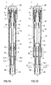
- Figure 1 shows two longitudinal sections in different section planes of an auto-injector 1, the different section planes approximately 90° rotated to each other.
- the auto-injector 1 comprises an elongate housing 2.
- a syringe 3, e.g. a Hypak syringe, with a hollow needle 4 is arranged in a proximal part of the auto-injector 1.
- a protective needle shield may be attached to the needle (not illustrated).
- a stopper 6 is arranged for sealing the syringe 3 distally and for displacing a liquid medicament M through the hollow needle 4.
- the syringe 3 is held in a tubular syringe carrier 7 and supported at its proximal end therein.
- a single drive spring 8 in the shape of a compression spring is arranged in a distal part of the auto-injector 1.
- a plunger 9 is arranged for forwarding the spring force of the drive spring 8.
- a retraction sleeve 10 is slidably arranged inside the housing 2 .
- the retraction sleeve 10 Before the injection is triggered the retraction sleeve 10 is in a maximum proximal position and prevented from moving in distal direction D by means of stops 11 caught behind latches 12 in the housing 2.
- a distal end of the drive spring 8 bears against an end face 13 of the retraction sleeve 10. Due to the stops 11 and latches 12 the force of the drive spring 8 is thus reacted into the housing 2.
- the proximal end of the drive spring 8 bears against a decoupling member 14 arranged around the plunger 9.
- the retraction sleeve Distally from the end face 13 the retraction sleeve has two or more resilient arms 15 for holding a stud 16 and keeping it from being moved in proximal direction P.
- the stud 16 is arranged at the distal end of the plunger 9.
- the stud 16 and the resilient arms 15 have corresponding ramp features for pushing the resilient arms 15 apart in order to allow the stud 16 and the plunger 9 to move in proximal direction P.
- the decoupling member 14 comprises a thrust face 17 for bearing against a proximal end of the drive spring 8. Proximally from the thrust face 17 two or more resilient decoupling arms 18 are provided at the decoupling member 14, the decoupling arms 18 having inner ramped surfaces bearing against a first shoulder 19 in the plunger 9 in proximal direction P.
- the resilient decoupling arms 18 are supported by an inner wall of the retraction sleeve 10 in this situation so they cannot flex outward and slip past the first shoulder 19.
- a trigger button 20 is arranged at the distal end D of the auto-injector 1.
- the trigger button 20 may be pushed in proximal direction P in order to start an injection.
- the resilient arms 15 are caught between two or more retainers 21 arranged at the trigger button 20 so the resilient arms 15 cannot flex outward and the stud 16 although proximally biased by the drive spring 8 cannot slip through.
- the syringe carrier 7 is engaged for joint axial movement with a syringe holder 22 which is slidably arranged in the retraction sleeve 10.
- the syringe holder 22 is provided with two or more resilient syringe holder arms 23 arranged distally.
- the syringe holder arms 23 have a respective inclined surface for bearing against a second shoulder 24 in the plunger 9 arranged proximally from the first shoulder 19. In the initial position shown in figure 1 the syringe holder arms 23 are supported by an inner surface of the housing 2 so they cannot flex outward and the second shoulder 24 cannot slip through.
- a respective number of apertures are provided in the retraction sleeve 10.
- Two resilient wedges 10.1 are arranged at a proximal end of the retraction sleeve 10.
- the housing 2 has two recesses 2.2 arranged to accommodate the resilient wedges 10.1 when the retraction sleeve 10 is in its proximal position.
- a skin interlock sleeve 25 is telescoped in the proximal end P of the housing 2.
- the syringe carrier 7 in turn is telescoped in the interlock sleeve 25.
- the interlock sleeve 25 is biased in proximal direction P by an interlock spring 26.
- Two resilient second latches 27 are arranged in the housing 2 near the proximal end P. In the state as delivered the second latches 27 are relaxed and extend inwardly through respective apertures 25.1 in the interlock sleeve 25 in a manner to prevent the syringe carrier 7 from translating in proximal direction P by the syringe carrier 7 abutting against respective distal faces 27.1 of the second latches 27.
- the syringe carrier 7, the syringe 3 and the needle 4 can therefore not be forwarded when pushed by the plunger 9.
- the auto-injector 1 In order to start an injection the auto-injector 1 has to be pressed against the injection site, e.g. a patient's skin. As a result the interlock sleeve 25 translates in distal direction D into the housing 2 (see figure 2 ). A proximal edge of the aperture 25.1 pushes against a proximal ramp 27.2 of the second latch 27 thereby flexing the second latch 27 outwards so the syringe carrier 7 comes clear of the distal faces 27.1 and may now translate in proximal direction P.
- a distal end of the interlock sleeve 25 supports the resilient wedges 10.1 from inside so they cannot be flexed inwards thus preventing the retraction sleeve 10 from translating in distal direction D.
- the trigger button 20 can now be pushed to release the drive spring 8 in order to insert the needle 4 into the injection site and to inject the medicament M.
- the interlock sleeve 25 will translate back into its proximal position under load of the interlock spring 26.
- the second latches 27 will flex inwards and block the syringe carrier 7 so the auto-injector 1 is in its as delivered state again.
- the sequence of operation can be reversed in this embodiment, i.e. the trigger button 20 may be pushed before pressing the auto-injector 1 against the injection site.
- the second shoulder 24 pushes the syringe holder 22, syringe carrier 7 and syringe 3 forward while no load is exerted onto the stopper 6.
- the hollow needle 4 appears from the proximal end P and is inserted into an injection site, e.g. a patient's skin.
- the decoupling arms 18 reach an aperture 34 in the retraction sleeve 10 so they are no longer kept from being flexed outward.
- the decoupling arms 18 are thus pushed outward by the first shoulder 19 pushing against its ramped surfaces so the first shoulder 19 can slip through in distal direction D as soon as the decoupling member 14 has hit the second abutment 33.
- the retraction sleeve 10 may not yet slide in distal direction D because of the resilient wedges 10.1 being held in the recess 2.2 between the housing 2 and the interlock sleeve 25 as long as the interlock sleeve 25 is in its distal position by the auto-injector 1 being kept pushed against the injection site.
- the interlock sleeve 25 will return to its proximal position (as in fig. 1 ) under load of the interlock spring 26 so the resilient wedges 10.1 are no longer supported from inside. Since the drive spring 8 tries to pull the retraction sleeve 10 in distal direction D, distal ramps of the resilient wedges 10.1 move along proximal ramps of the recesses 2.2 thereby flexing the resilient wedges inwards as the retraction sleeve 10 starts translating in distal direction.
- the syringe holder 22 is taken along in distal direction D by the retraction sleeve 10, e.g. by a front face 35.
- the syringe 3 and needle 4 are retracted into a safe position inside the housing 2, e.g. into the initial position.
- the plunger 9, no longer bearing against the decoupling arms 18 is pulled back too.
- the latches 12 and the stops 11 at the retraction sleeve 10 are not absolutely required. Retraction can be triggered by removal of the auto-injector 1 from the injection site alone. However, the latches 12 and the stops 11 facilitate assembly of the auto-injector 1 and give an initial position to the retraction sleeve 10. Furthermore, the stops 11 as well as lugs on the decoupling member 14 for disengaging the latches 12 and the stops 11 run in a slot 2.6 in the housing 2 thus preventing the retraction sleeve 10 and the decoupling member 14 from rotating.
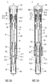
- Figure 3 shows two longitudinal sections in different section planes of another embodiment of an auto-injector 1, the different section planes approximately 90° rotated to each other.
- the auto-injector 1 comprises an elongate housing 2.
- a syringe 3, e.g. a Hypak syringe, with a hollow needle 4 is arranged in a proximal part of the auto-injector 1.
- a protective needle shield may be attached to the needle (not illustrated).
- a stopper 6 is arranged for sealing the syringe 3 distally and for displacing a liquid medicament M through the hollow needle 4.
- the syringe 3 is held in a tubular syringe carrier 7 and supported at its proximal end therein.
- a single drive spring 8 in the shape of a compression spring is arranged in a distal part of the auto-injector 1.
- a plunger 9 is arranged for forwarding the spring force of the drive spring 8.
- a retraction sleeve 10 is slidably arranged inside the housing 2 . Before the injection is triggered the retraction sleeve 10 is in a maximum proximal position abutting against a stop 2.4 in the housing 2. A distal end of the drive spring 8 bears against an end face 13 of the retraction sleeve 10. The proximal end of the drive spring 8 bears against a decoupling member 14 arranged around the plunger 9.
- the decoupling member 14 comprises a thrust face 17 for bearing against a proximal end of the drive spring 8. Proximally from the thrust face 17 two or more resilient decoupling arms 18 are provided at the decoupling member 14, the decoupling arms 18 having inner ramped surfaces arranged for bearing against a first shoulder 19 in the plunger 9 in proximal direction P. In the as delivered state in figure 3 the first shoulder 19 is situated a small distance proximally from the ramped surfaces of the decoupling arms 18.
- the resilient decoupling arms 18 may be supported by an inner wall of the retraction sleeve 10 for preventing them from being flexed outward and slip past the first shoulder 19. Apertures 34 are provided in the retraction sleeve 10 for allowing the decoupling arms 18 to flex outwards.
- a trigger button 20 is arranged at the distal end D of the auto-injector 1.
- the trigger button 20 is arranged to be pushed in proximal direction P in order to start an injection.
- the syringe carrier 7 is engaged for joint axial movement with a syringe holder 22 which is slidably arranged in the retraction sleeve 10.
- the syringe holder 22 is provided with two or more resilient syringe holder arms 23 arranged distally.
- the syringe holder arms 23 have a respective inclined surface for bearing against a second shoulder 24 in the plunger 9 arranged proximally from the first shoulder 19.
- Two resilient wedges 10.1 are arranged at a proximal end of the retraction sleeve 10.
- the housing 2 has two recesses 2.2 arranged to accommodate the resilient wedges 10.1 when the retraction sleeve 10 is in its proximal position.
- a skin interlock sleeve 45 is telescoped in the proximal end P of the housing 2.
- the syringe carrier 7 in turn is telescoped in the interlock sleeve 45.
- the interlock sleeve 45 is biased in proximal direction P by an interlock spring 26.
- the interlock sleeve 45 is coupled with the syringe carrier 7 by resilient clips 45.1 provided in the interlock sleeve 45.
- the clips 45.1 are engaged in a respective recess in the syringe carrier 7 and outwardly supported by the housing 2 so they cannot flex outward.
- the interlock sleeve 45, the syringe carrier 7 with the syringe 3 and the needle 4, the syringe holder 22 and the plunger 9 are coupled for joined axial translation.
- the recess in the syringe carrier 7 and the clip 45.1 have ramps arranged to flex the clip 45.1 outwards when the syringe carrier 7 and the interlock sleeve 45 are pushed against each other in longitudinal direction.
- the syringe carrier 7, the syringe 3 and the needle 4 can therefore not be forwarded when pushed by the plunger 9.
- the trigger button 20 is secured on the housing 2 by means of clips 20.1 so it cannot translate in distal direction D further than shown in figure 4 .
- a central shaft 20.2 extends from the trigger button 20 in proximal direction towards the plunger 9.
- Another set of resilient clips 10.2 are arranged on the retraction sleeve 10 proximally from the end face 13 inside the drive spring 8 arranged for abutting against a shoulder 20.5 in the central shaft 20.2 in a manner to prevent the trigger button 20 from being actuated in the as delivered state (see figure 9 ).
- the retraction sleeve 10 can not translate in proximal direction P due to its proximal end abutting against the stop 2.4.
- the resilient clips 10.2 may be disengaged from the trigger button 20 by respective bars 9.1 extending distally from the distal end of the plunger 9 upon translation of the plunger 9 in distal direction D.
- a set of resilient catches 10.3 (shown in Figure 5B ) are arranged on the retraction sleeve 10 proximally from the end face 13 inside the drive spring 8 for engaging respective catches 14.1 extending distally from the decoupling member 14.
- the catches 14.1 and 10.3 are engaged with each other in a manner to prevent the decoupling member 14 from translating in proximal direction P as long as the trigger button 20 is not pushed.
- the auto-injector 1 In order to start an injection the auto-injector 1 has to be pressed against the injection site, e.g. a patient's skin. As a result the interlock sleeve 45 translates in distal direction D into the housing 2 by a small distance taking with it the syringe carrier 7, the syringe 3 with the needle 4, the syringe holder 22 and the plunger 9 until the first shoulder 19 meets the ramped surfaces of the decoupling arms 18. At the same time the clips 45.1 enter a space 2.3 in the housing 2 where they are no longer supported outwardly so they may now flex outwards for decoupling the interlock sleeve 45 from the syringe carrier 7.
- a distal end of the interlock sleeve 45 When translated into the housing 2 a distal end of the interlock sleeve 45 supports the resilient wedges 10.1 from inside so they cannot be flexed inwards thus preventing the retraction sleeve 10 from translating in distal direction D.
- the interlock sleeve 45 will translate back into its proximal position under load of the interlock spring 26.
- the second shoulder 24 pushes the syringe holder 22, syringe carrier 7 and syringe 3 forward while no load is exerted onto the stopper 6.
- the hollow needle 4 appears from the proximal end P and is inserted into the injection site, e.g. a patient's skin.
- the retraction sleeve 10 may not yet slide in distal direction D because of the resilient wedges 10.1 being held in the recess 2.2 between the housing 2 and the interlock sleeve 45 as long as the interlock sleeve 45 is in its distal position by the auto-injector 1 being kept pushed against the injection site.
- the interlock sleeve 45 will return to its proximal position (as in fig. 3 ) under load of the interlock spring 26 so the resilient wedges 10.1 are no longer supported from inside. Since the drive spring 8 tries to pull the retraction sleeve 10 in distal direction D, distal ramps of the resilient wedges 10.1 move along proximal ramps of the recesses 2.2 thereby flexing the resilient wedges 10.1 inwards as the retraction sleeve 10 starts translating in distal direction D.
- the syringe holder 22 is taken along in distal direction D by the retraction sleeve 10, e.g. by a front face 35.
- the syringe 3 and needle 4 are retracted into a safe position inside the housing 2, e.g. into the initial position.
- the plunger 9, no longer bearing against the decoupling arms 18 is pulled back too.
- the auto-injector 1 of figure 3 is arranged to retract the syringe 3 and needle 4 at any time during the injection if pulled away from the skin.
- the retraction sleeve held by the interlock sleeve 25 if released before the end of injection will not retract the syringe 3 if the decoupling member 14 does not release the plunger 9 at the same time.
- the plunger 9 is only released at its end of travel when the decoupling member 14 meets the aperture 34.
- the aperture 34 In order to retract the syringe 3 before the end of injection the aperture 34 needs to be available at any time during plunger travel. The aperture 34 therefore extends right to the position of the decoupling arms 18 in the as delivered state. However, the aperture is angularly misaligned with respect to the decoupling arms 18 by a small angle so the decoupling member 14 and the plunger 9 cannot decouple.
- the interlock sleeve 45 translates in proximal direction under load of the interlock spring 26 so the resilient wedges 10.1 are no longer supported from inside.
- distal ramps of the resilient wedges 10.1 move along proximal ramps of the recesses 2.2 thereby flexing the resilient wedges inwards as the retraction sleeve 10 starts translating in distal direction.
- the retraction sleeve 10 is arranged to rotate in this situation by a small angle thus aligning the aperture 34 and the decoupling arms 18, so the decoupling member 18 decouples from the plunger 9 and the syringe 3 and the needle 4 are retracted into a safe position inside the housing 2.
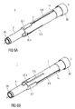
- Decoupling member 14 and hence decoupling arms 18 are prevented from rotating in housing 2 by one or more lugs on decoupling member 14 which engage in longitudinal slots 2.6 in housing 2, as shown in Figure 6a and 6b .
- a cam track 2.5 is arranged in the housing 2 and a cam follower 10.4 in the retraction sleeve 10 (see figs. 6a and 6b ).
- the cam track 2.5 is essentially parallel to the longitudinal axis of the auto-injector 1 with a short angled section at its proximal end. As long as the cam follower 10.4 runs in the parallel section of the cam track, the retraction sleeve 10 is prevented from rotating.
- Figure 7 shows the auto-injector of figure 3 with the actuated trigger button 20.
- Figure 8 is a cross section in the section plane Vill-Vill illustrating the angular misalignment before the retraction is triggered.
- the auto-injector 1 of figure 3 may have the aperture 34 in the retraction sleeve 10 as in figures 1 and 2 . In this case the needle retraction would occur only at the end of dose.
- the auto-injector 1 of figures 1 and 2 could be combined with the aperture 34, the cam track 2.5 and the cam follower 10.4 of figures 3 to 8 in order to provide immediate needle retraction at any point during the injection cycle.
- the cam track may likewise be arranged in the retraction sleeve 10 and the cam follower in the housing 2.
- the housing 2 may have at least one viewing window for inspecting the syringe 3.
- the auto-injector 1 may preferably be used for subcutaneous or intra-muscular injection, particularly for delivering one of an analgetic, an anticoagulant, insulin, an insulin derivate, heparin, Lovenox, a vaccine, a growth hormone, a peptide hormone, a proteine, antibodies and complex carbohydrates.
- the aforementioned arrangement for coupling the plunger 9 to either, the syringe 3 or the stopper 6, may be applied in any auto-injector having a plunger for forwarding a force of a drive means to a syringe with a stopper.
- the primary advantage of this arrangement ensures the load from the drive means is not transferred directly to the stopper until the needle is inserted in the patient, thus avoiding a wet injection.
- the arrangement comprises the syringe holder 22 and associated syringe holder arms 23, a shoulder (e.g.
- the spring means or other drive means the ability to retract the syringe or to forward a needle shroud after injection and other features described herein are not required for the prevention of a wet injection.
Priority Applications (8)
| Application Number | Priority Date | Filing Date | Title |
|---|---|---|---|
| EP10167480A EP2399628A1 (fr) | 2010-06-28 | 2010-06-28 | Auto-injecteur |
| US13/807,268 US9707356B2 (en) | 2010-06-28 | 2011-06-20 | Auto-injector |
| PCT/EP2011/060504 WO2012000872A1 (fr) | 2010-06-28 | 2011-06-22 | Auto-injecteur |
| DK11729285.4T DK2585140T3 (da) | 2010-06-28 | 2011-06-22 | Autoinjektor |
| EP11729285.4A EP2585140B1 (fr) | 2010-06-28 | 2011-06-22 | Auto-injecteur |
| JP2013517195A JP6223183B2 (ja) | 2010-06-28 | 2011-06-22 | 自動注射器 |
| CA2802520A CA2802520A1 (fr) | 2010-06-28 | 2011-06-22 | Auto-injecteur |
| TW100122105A TW201212965A (en) | 2010-06-28 | 2011-06-24 | Auto-injector |
Applications Claiming Priority (1)
| Application Number | Priority Date | Filing Date | Title |
|---|---|---|---|
| EP10167480A EP2399628A1 (fr) | 2010-06-28 | 2010-06-28 | Auto-injecteur |
Publications (1)
| Publication Number | Publication Date |
|---|---|
| EP2399628A1 true EP2399628A1 (fr) | 2011-12-28 |
Family
ID=43027644
Family Applications (2)
| Application Number | Title | Priority Date | Filing Date |
|---|---|---|---|
| EP10167480A Ceased EP2399628A1 (fr) | 2010-06-28 | 2010-06-28 | Auto-injecteur |
| EP11729285.4A Active EP2585140B1 (fr) | 2010-06-28 | 2011-06-22 | Auto-injecteur |
Family Applications After (1)
| Application Number | Title | Priority Date | Filing Date |
|---|---|---|---|
| EP11729285.4A Active EP2585140B1 (fr) | 2010-06-28 | 2011-06-22 | Auto-injecteur |
Country Status (7)
| Country | Link |
|---|---|
| US (1) | US9707356B2 (fr) |
| EP (2) | EP2399628A1 (fr) |
| JP (1) | JP6223183B2 (fr) |
| CA (1) | CA2802520A1 (fr) |
| DK (1) | DK2585140T3 (fr) |
| TW (1) | TW201212965A (fr) |
| WO (1) | WO2012000872A1 (fr) |
Cited By (10)
| Publication number | Priority date | Publication date | Assignee | Title |
|---|---|---|---|---|
| WO2013175136A1 (fr) | 2012-05-25 | 2013-11-28 | Aptar France Sas | Autoinjecteur |
| WO2013175137A1 (fr) | 2012-05-25 | 2013-11-28 | Aptar France Sas | Autoinjecteur |
| WO2013175139A1 (fr) | 2012-05-25 | 2013-11-28 | Aptar France Sas | Autoinjecteur avec un retardateur ayant un train épicycloidal pour retarder la retraction de l'aiguille |
| FR2990864A1 (fr) * | 2012-05-25 | 2013-11-29 | Valois Sas | Autoinjecteur |
| FR2990868A1 (fr) * | 2012-05-25 | 2013-11-29 | Aptar France Sas | Autoinjecteur |
| WO2014049214A1 (fr) | 2012-09-27 | 2014-04-03 | Aptar France Sas | Autoinjecteur |
| WO2014082959A1 (fr) * | 2012-11-29 | 2014-06-05 | Novo Nordisk A/S | Dispositif d'injection ayant un protecteur d'aiguille intégré |
| EP2868338A1 (fr) * | 2013-10-31 | 2015-05-06 | Sanofi-Aventis Deutschland GmbH | Dispositifs d'administration de médicaments |
| US9717851B2 (en) | 2012-05-25 | 2017-08-01 | Aptar France Sas | Autoinjector |
| US9931467B2 (en) | 2012-05-25 | 2018-04-03 | Aptar France Sas | Autoinjector |
Families Citing this family (40)
| Publication number | Priority date | Publication date | Assignee | Title |
|---|---|---|---|---|
| US20110098656A1 (en) * | 2005-09-27 | 2011-04-28 | Burnell Rosie L | Auto-injection device with needle protecting cap having outer and inner sleeves |
| WO2009044401A2 (fr) | 2007-10-02 | 2009-04-09 | Yossi Gross | Pompe à médicament externe |
| JP6165055B2 (ja) * | 2010-06-28 | 2017-07-19 | サノフィ−アベンティス・ドイチュラント・ゲゼルシャフト・ミット・ベシュレンクテル・ハフツング | 自動注射器 |
| EP2438939A1 (fr) * | 2010-10-08 | 2012-04-11 | Sanofi-Aventis Deutschland GmbH | Agencement pour coupler un piston avec une seringue ou un butoir |
| EP2438944A1 (fr) * | 2010-10-08 | 2012-04-11 | Sanofi-Aventis Deutschland GmbH | Auto-injecteur |
| USRE48593E1 (en) | 2010-12-21 | 2021-06-15 | Sanofi-Aventis Deutschland Gmbh | Auto-injector |
| EP2468333A1 (fr) * | 2010-12-21 | 2012-06-27 | Sanofi-Aventis Deutschland GmbH | Auto-injecteur |
| EP2716318A1 (fr) * | 2012-10-04 | 2014-04-09 | Sanofi-Aventis Deutschland GmbH | Dispositif d'administration de médicament avec indicateur d'initiation d'administration de médicament |
| GB2515038A (en) | 2013-06-11 | 2014-12-17 | Cilag Gmbh Int | Injection device |
| GB2515039B (en) | 2013-06-11 | 2015-05-27 | Cilag Gmbh Int | Injection Device |
| GB2517896B (en) | 2013-06-11 | 2015-07-08 | Cilag Gmbh Int | Injection device |
| GB2515032A (en) | 2013-06-11 | 2014-12-17 | Cilag Gmbh Int | Guide for an injection device |
| DE102013018639A1 (de) | 2013-11-06 | 2014-07-24 | Fresenius Medical Care Deutschland Gmbh | Konnektor |
| EP2902061A1 (fr) | 2014-01-30 | 2015-08-05 | Sanofi-Aventis Deutschland GmbH | Dispositifs d'administration de médicaments |
| EP3102261A4 (fr) * | 2014-02-03 | 2017-11-08 | UNL Holdings LLC | Seringue à aiguille sélectionnable avec piston de rétraction |
| EP3981450A1 (fr) * | 2015-02-27 | 2022-04-13 | Amgen, Inc | Dispositif d'administration de médicament ayant un mécanisme de protection d'aiguille présentant un seuil réglable de résistance au mouvement de l'élément de protection d'aiguille |
| US10576207B2 (en) | 2015-10-09 | 2020-03-03 | West Pharma. Services IL, Ltd. | Angled syringe patch injector |
| JP7017512B2 (ja) | 2015-10-09 | 2022-02-08 | ウェスト ファーマ サービシーズ イスラエル リミテッド | 充填済流体容器の屈曲流体路型付属物 |
| WO2017123783A1 (fr) | 2016-01-12 | 2017-07-20 | Pharma Consult Ges.M.B.H. | Dspositif d'injection |
| JP6542481B2 (ja) | 2016-01-21 | 2019-07-10 | ウェスト ファーマ サービシーズ イスラエル リミテッド | システム |
| EP3711793B1 (fr) | 2016-01-21 | 2021-12-01 | West Pharma Services IL, Ltd. | Procédé de connexion d'une cartouche sur un injecteur automatique |
| CN113041432B (zh) | 2016-01-21 | 2023-04-07 | 西医药服务以色列有限公司 | 包括视觉指示物的药剂输送装置 |
| EP3429664B1 (fr) * | 2016-03-16 | 2019-12-04 | Eli Lilly and Company | Ensemble déclencheur pour dispositif d'injection automatique de médicament |
| US11389597B2 (en) | 2016-03-16 | 2022-07-19 | West Pharma. Services IL, Ltd. | Staged telescopic screw assembly having different visual indicators |
| JP6869327B2 (ja) | 2016-08-01 | 2021-05-12 | ウェスト ファーマ サービシーズ イスラエル リミテッド | 回転防止カートリッジ |
| WO2018125629A1 (fr) | 2016-12-27 | 2018-07-05 | Action Medical Technologies, Llc | Appareils et procédé d'injection de médicaments |
| CN115025328A (zh) * | 2017-05-05 | 2022-09-09 | 里珍纳龙药品有限公司 | 自动注射器和相关使用方法 |
| CN110869072B (zh) | 2017-05-30 | 2021-12-10 | 西部制药服务有限公司(以色列) | 用于穿戴式注射器的模块化驱动机构 |
| US11311683B2 (en) | 2017-10-16 | 2022-04-26 | Nspire Medical Technologies, Llc | Self-retracting mechanized syringe and methods of use |
| JP7301817B2 (ja) | 2017-10-20 | 2023-07-03 | ウエスト ファーマスーティカル サービシーズ インコーポレイテッド | 半再利用可能な手掌作動式の注射システム |
| CN108392699A (zh) * | 2018-04-04 | 2018-08-14 | 杨博 | 用于注射的装置及其方法 |
| US11224696B2 (en) | 2018-07-10 | 2022-01-18 | Action Medical Technologies, Llc | Apparatuses and method for injecting medicaments |
| USD893712S1 (en) | 2019-02-15 | 2020-08-18 | Action Medical Technologies, Llc | Grip for autoinjectors |
| CA3132163A1 (fr) * | 2019-03-15 | 2020-09-24 | Eli Lilly And Company | Systeme d'injection automatique |
| CN113811341B (zh) * | 2019-03-22 | 2023-03-28 | 辉美医疗器械有限公司 | 具有双稳态离合器板的自动注射装置 |
| EP3808393A1 (fr) * | 2019-10-15 | 2021-04-21 | Ypsomed AG | Fixation de cartouche pour dispositif d'administration de médicaments |
| JP2023503922A (ja) * | 2019-11-21 | 2023-02-01 | イノキャット リミテッド | 液体供給装置及び方法 |
| EP4126128A4 (fr) | 2020-03-25 | 2023-09-20 | Action Medical Technologies, LLC | Appareils et procédés d'injection de médicaments |
| US11759576B2 (en) | 2020-06-05 | 2023-09-19 | Action Medical Technologies, Llc | Parenteral injection apparatus |
| USD1007676S1 (en) | 2021-11-16 | 2023-12-12 | Regeneron Pharmaceuticals, Inc. | Wearable autoinjector |
Citations (5)
| Publication number | Priority date | Publication date | Assignee | Title |
|---|---|---|---|---|
| US5267963A (en) * | 1992-08-21 | 1993-12-07 | Nicholas Bachynsky | Medication injection device |
| US20020095120A1 (en) | 2000-08-29 | 2002-07-18 | Andre Larsen | Automatic injection device |
| WO2009062508A1 (fr) * | 2007-11-12 | 2009-05-22 | Bang & Olufsen Medicom A/S | Injecteur automatique avec tige de libération rotative |
| WO2009081103A1 (fr) * | 2007-12-20 | 2009-07-02 | Ucb Pharma S.A. | Auto-injecteur pourvu d'un bloque-seringue pour bloquer l'élément de couplage de corps de seringue et la seringue couplée associée en position dite de rétractation |
| US7717877B2 (en) * | 2003-07-31 | 2010-05-18 | Sid Technologies, Llc | Injecting apparatus |
Family Cites Families (9)
| Publication number | Priority date | Publication date | Assignee | Title |
|---|---|---|---|---|
| DE3715340C2 (de) * | 1987-05-08 | 1995-10-19 | Haselmeier Wilhelm Fa | Injektionsgerät |
| US20030105430A1 (en) * | 2001-11-30 | 2003-06-05 | Elan Pharma International Limited Wil House | Automatic injector |
| DE10229122B4 (de) * | 2002-06-28 | 2006-09-07 | Tecpharma Licensing Ag | Verabreichungsgerät mit rücksetzbarer Betätigungssperre |
| DK1542744T3 (da) * | 2002-09-24 | 2009-09-28 | Shl Group Ab | Injektionsanordning |
| WO2004047892A1 (fr) * | 2002-11-25 | 2004-06-10 | Tecpharma Licensing Ag | Dispositif d'injection pourvu d'une protection d'aiguille |
| CH696421A5 (de) * | 2003-12-18 | 2007-06-15 | Tecpharma Licensing Ag | Autoinjektor mit Arretierung des Wirkstoffbehälters. |
| GB2433032A (en) * | 2005-12-08 | 2007-06-13 | Owen Mumford Ltd | Syringe with dose adjustment means |
| US9242044B2 (en) * | 2007-07-06 | 2016-01-26 | Novo Nordisk A/S | Automatic injection device |
| US8647309B2 (en) * | 2008-05-02 | 2014-02-11 | Sanofi-Aventis Deutschland Gmbh | Medication delivery device |
-
2010
- 2010-06-28 EP EP10167480A patent/EP2399628A1/fr not_active Ceased
-
2011
- 2011-06-20 US US13/807,268 patent/US9707356B2/en active Active
- 2011-06-22 DK DK11729285.4T patent/DK2585140T3/da active
- 2011-06-22 JP JP2013517195A patent/JP6223183B2/ja active Active
- 2011-06-22 EP EP11729285.4A patent/EP2585140B1/fr active Active
- 2011-06-22 WO PCT/EP2011/060504 patent/WO2012000872A1/fr active Application Filing
- 2011-06-22 CA CA2802520A patent/CA2802520A1/fr not_active Abandoned
- 2011-06-24 TW TW100122105A patent/TW201212965A/zh unknown
Patent Citations (5)
| Publication number | Priority date | Publication date | Assignee | Title |
|---|---|---|---|---|
| US5267963A (en) * | 1992-08-21 | 1993-12-07 | Nicholas Bachynsky | Medication injection device |
| US20020095120A1 (en) | 2000-08-29 | 2002-07-18 | Andre Larsen | Automatic injection device |
| US7717877B2 (en) * | 2003-07-31 | 2010-05-18 | Sid Technologies, Llc | Injecting apparatus |
| WO2009062508A1 (fr) * | 2007-11-12 | 2009-05-22 | Bang & Olufsen Medicom A/S | Injecteur automatique avec tige de libération rotative |
| WO2009081103A1 (fr) * | 2007-12-20 | 2009-07-02 | Ucb Pharma S.A. | Auto-injecteur pourvu d'un bloque-seringue pour bloquer l'élément de couplage de corps de seringue et la seringue couplée associée en position dite de rétractation |
Cited By (22)
| Publication number | Priority date | Publication date | Assignee | Title |
|---|---|---|---|---|
| US9707357B2 (en) | 2012-05-25 | 2017-07-18 | Aptar France Sas | Autoinjector |
| WO2013175139A1 (fr) | 2012-05-25 | 2013-11-28 | Aptar France Sas | Autoinjecteur avec un retardateur ayant un train épicycloidal pour retarder la retraction de l'aiguille |
| US10668217B2 (en) | 2012-05-25 | 2020-06-02 | Aptar France Sas | Autoinjector |
| WO2013175142A1 (fr) | 2012-05-25 | 2013-11-28 | Aptar France Sas | Autoinjecteur. |
| WO2013175148A1 (fr) * | 2012-05-25 | 2013-11-28 | Aptar France Sas | Autoinjecteur. |
| WO2013175140A1 (fr) | 2012-05-25 | 2013-11-28 | Aptar France Sas | Autoinjecteur |
| FR2990864A1 (fr) * | 2012-05-25 | 2013-11-29 | Valois Sas | Autoinjecteur |
| FR2990868A1 (fr) * | 2012-05-25 | 2013-11-29 | Aptar France Sas | Autoinjecteur |
| US9931467B2 (en) | 2012-05-25 | 2018-04-03 | Aptar France Sas | Autoinjector |
| US9717851B2 (en) | 2012-05-25 | 2017-08-01 | Aptar France Sas | Autoinjector |
| US9707343B2 (en) | 2012-05-25 | 2017-07-18 | Aptar France Sas | Autoinjector comprising a time delay device having a planetary gear set for delaying the retraction of the needle |
| WO2013175137A1 (fr) | 2012-05-25 | 2013-11-28 | Aptar France Sas | Autoinjecteur |
| WO2013175136A1 (fr) | 2012-05-25 | 2013-11-28 | Aptar France Sas | Autoinjecteur |
| US9616174B2 (en) | 2012-05-25 | 2017-04-11 | Aptar France Sas | Autoinjector |
| WO2014049214A1 (fr) | 2012-09-27 | 2014-04-03 | Aptar France Sas | Autoinjecteur |
| EP3308814A1 (fr) | 2012-09-27 | 2018-04-18 | APTAR France SAS | Autoinjecteur |
| US9649451B2 (en) | 2012-11-29 | 2017-05-16 | Novo Nordisk A/S | Injection device with integrated needle shield |
| WO2014082959A1 (fr) * | 2012-11-29 | 2014-06-05 | Novo Nordisk A/S | Dispositif d'injection ayant un protecteur d'aiguille intégré |
| CN104884104A (zh) * | 2012-11-29 | 2015-09-02 | 诺和诺德股份有限公司 | 具有集成针护罩的注射装置 |
| US10857295B2 (en) | 2013-10-31 | 2020-12-08 | Sanofi-Aventis Deutschland Gmbh | Medicament delivery device |
| WO2015062915A1 (fr) * | 2013-10-31 | 2015-05-07 | Sanofi-Aventis Deutschland Gmbh | Dispositif d'administration de médicament |
| EP2868338A1 (fr) * | 2013-10-31 | 2015-05-06 | Sanofi-Aventis Deutschland GmbH | Dispositifs d'administration de médicaments |
Also Published As
| Publication number | Publication date |
|---|---|
| EP2585140A1 (fr) | 2013-05-01 |
| EP2585140B1 (fr) | 2019-07-24 |
| DK2585140T3 (da) | 2019-10-14 |
| JP6223183B2 (ja) | 2017-11-01 |
| CA2802520A1 (fr) | 2012-01-05 |
| WO2012000872A1 (fr) | 2012-01-05 |
| TW201212965A (en) | 2012-04-01 |
| US20130310759A1 (en) | 2013-11-21 |
| US9707356B2 (en) | 2017-07-18 |
| JP2013529520A (ja) | 2013-07-22 |
Similar Documents
| Publication | Publication Date | Title |
|---|---|---|
| US11813436B2 (en) | Auto-injector | |
| US9707356B2 (en) | Auto-injector | |
| US9427531B2 (en) | Auto-injector | |
| US9352089B2 (en) | Auto-injector | |
| EP2585141B1 (fr) | Auto-injecteur | |
| EP2585138B1 (fr) | Auto-injecteur | |
| EP2585134B1 (fr) | Auto-injecteur avec élément d'amortissement d'injection | |
| EP2399632A1 (fr) | Auto-injecteur avec un ressort à compression unique et avec un bouton poussoir latéral | |
| EP2441487A1 (fr) | Auto-injecteur |
Legal Events
| Date | Code | Title | Description |
|---|---|---|---|
| AK | Designated contracting states |
Kind code of ref document: A1 Designated state(s): AL AT BE BG CH CY CZ DE DK EE ES FI FR GB GR HR HU IE IS IT LI LT LU LV MC MK MT NL NO PL PT RO SE SI SK SM TR |
|
| AX | Request for extension of the european patent |
Extension state: BA ME RS |
|
| PUAI | Public reference made under article 153(3) epc to a published international application that has entered the european phase |
Free format text: ORIGINAL CODE: 0009012 |
|
| STAA | Information on the status of an ep patent application or granted ep patent |
Free format text: STATUS: THE APPLICATION HAS BEEN REFUSED |
|
| 18R | Application refused |
Effective date: 20120205 |