EP2399016B1 - Method for operating a final stage for at least one piezoactuator - Google Patents
Method for operating a final stage for at least one piezoactuator Download PDFInfo
- Publication number
- EP2399016B1 EP2399016B1 EP10700511A EP10700511A EP2399016B1 EP 2399016 B1 EP2399016 B1 EP 2399016B1 EP 10700511 A EP10700511 A EP 10700511A EP 10700511 A EP10700511 A EP 10700511A EP 2399016 B1 EP2399016 B1 EP 2399016B1
- Authority
- EP
- European Patent Office
- Prior art keywords
- time
- current
- time window
- operating
- piezoactuator
- Prior art date
- Legal status (The legal status is an assumption and is not a legal conclusion. Google has not performed a legal analysis and makes no representation as to the accuracy of the status listed.)
- Active
Links
- 238000000034 method Methods 0.000 title claims description 29
- 238000007599 discharging Methods 0.000 claims description 15
- 238000004590 computer program Methods 0.000 claims description 10
- 230000002093 peripheral effect Effects 0.000 claims description 3
- 230000001419 dependent effect Effects 0.000 claims description 2
- 238000013500 data storage Methods 0.000 claims 1
- 238000010586 diagram Methods 0.000 description 13
- 238000002347 injection Methods 0.000 description 10
- 239000007924 injection Substances 0.000 description 10
- 238000012546 transfer Methods 0.000 description 5
- 239000008186 active pharmaceutical agent Substances 0.000 description 4
- 230000006870 function Effects 0.000 description 4
- 238000012360 testing method Methods 0.000 description 4
- 230000006399 behavior Effects 0.000 description 2
- 238000012795 verification Methods 0.000 description 2
- 101001098880 Homo sapiens Purkinje cell protein 2 homolog Proteins 0.000 description 1
- 102100028516 Receptor-type tyrosine-protein phosphatase U Human genes 0.000 description 1
- 230000001427 coherent effect Effects 0.000 description 1
- 238000002485 combustion reaction Methods 0.000 description 1
- 230000000694 effects Effects 0.000 description 1
- 238000005259 measurement Methods 0.000 description 1
- 230000002035 prolonged effect Effects 0.000 description 1
- 230000000630 rising effect Effects 0.000 description 1
- 239000000243 solution Substances 0.000 description 1
Images


Classifications
-
- H—ELECTRICITY
- H02—GENERATION; CONVERSION OR DISTRIBUTION OF ELECTRIC POWER
- H02N—ELECTRIC MACHINES NOT OTHERWISE PROVIDED FOR
- H02N2/00—Electric machines in general using piezoelectric effect, electrostriction or magnetostriction
- H02N2/02—Electric machines in general using piezoelectric effect, electrostriction or magnetostriction producing linear motion, e.g. actuators; Linear positioners ; Linear motors
- H02N2/06—Drive circuits; Control arrangements or methods
- H02N2/065—Large signal circuits, e.g. final stages
- H02N2/067—Large signal circuits, e.g. final stages generating drive pulses
-
- F—MECHANICAL ENGINEERING; LIGHTING; HEATING; WEAPONS; BLASTING
- F02—COMBUSTION ENGINES; HOT-GAS OR COMBUSTION-PRODUCT ENGINE PLANTS
- F02D—CONTROLLING COMBUSTION ENGINES
- F02D41/00—Electrical control of supply of combustible mixture or its constituents
- F02D41/20—Output circuits, e.g. for controlling currents in command coils
- F02D41/2096—Output circuits, e.g. for controlling currents in command coils for controlling piezoelectric injectors
Definitions
- the invention relates to a method for operating an output stage for at least one piezoelectric actuator, an arrangement for operating an output stage for at least one piezoelectric actuator, a computer program and a computer program product.
- control units for so-called memory injection or common-rail or CR-piezo systems (DS) and gasoline direct injection or BDE piezo systems (GS), which include piezo actuators for loading cylinders is based on system-related requirements of a cylinder Select (Cylinder Select) is turned off at different times at the end of a charge / discharge operation.
- a cylinder Select Cylinder Select
- BDE piezo systems the cylinder selection is switched off exactly after the end of the charging or discharging time. This occurs regardless of whether there is still energy in a transfer inductance of a piezo output stage at this time.
- the invention relates to a method for operating an output stage for at least one piezoactuator, which is assigned to a cylinder and designed to drive a valve element of this cylinder.
- it is checked during a phase of operation falls below a current flowing through the piezoelectric actuator current below a desired current, whether a time for falling below or outside a time window.
- a criterion for an end of the operating phase is provided. If the time is outside the time window, the operating phase is continued and a subsequent current pulse or current pulse is controlled via the desired current. The subsequent current pulse is alternatively controlled for a turn-on time, if the time is within the time window.
- the current operating phase is terminated, so that a new operating phase can begin, in which typically a new setpoint current is provided.
- the number of current pulses depends on the selected operating point.
- a charge is applied linearly to the piezoelectric actuator with the current. If the time is within the time window and a usually time-controlled current pulse is terminated when the zero-current limit is undershot, it is also possible that a feedback signal is switched off. Furthermore, a cylinder select switch can be switched in analogy to this feedback signal. In doing so, possibly also several time-controlled current pulses, the number of which can be firmly defined, are discontinued. In addition, in the subsequent operating phase, a further piezoelectric actuator, which is assigned to a further cylinder, are energized.
- the time window is usually at the end of an operating time of the operating phase.
- the time window has a length of 0 to 25 ⁇ s, depending on a length of the operating phase.
- the switch-on time is dependent in a variant of a time interval, which is determined by the time for falling below the time window and the end of the time window or a time at which the time window is usually completed.
- the length of the time window is given to an application-specific integrated circuit, which can be arranged within a control device, via a serial peripheral interface.
- the method can be carried out for an operating phase designed as a charging phase in which the piezoactuator is charged and / or for an operating phase designed as a discharge phase in which the piezoactuator is discharged.
- the invention further relates to an arrangement for operating an output stage for at least one piezoelectric actuator.
- the arrangement is designed to measure a current provided to the piezoelectric actuator during an operating phase of the output stage and to check at which time the current falls below a nominal current and whether this time is outside or within a time window.
- the arrangement is also designed to continue the operating phase and to control a subsequent current pulse or current pulse over the desired current, if the time is outside the time window.
- the arrangement is designed to control the subsequent current pulse alternatively over a switch-on time, if the time is within the time window.
- the arrangement can have at least one measuring module for measuring the current, at least one test module for checking whether the time is inside or outside the window and at least one switching module for current-controlled or timed switching of the current and thus of the current pulse.
- the arrangement described is designed to carry out all the steps of the presented method.
- individual steps of this method can also be carried out by individual modules of the arrangement.
- functions of the arrangement or functions of individual modules of the arrangement can be implemented as steps of the method.
- steps of the method are realized as functions of individual modules of the arrangement or of the entire arrangement.
- the invention further relates to a computer program with program code means in order to perform all the steps of a described method when the computer program is executed on a computer or a corresponding arithmetic unit, in particular in an arrangement according to the invention.
- the computer program product according to the invention with program code means which are stored on a computer-readable data carrier is designed to carry out all the steps of a described method when the computer program is executed on a computer or a corresponding arithmetic unit, in particular in an arrangement according to the invention.
- the present invention combines the techniques used in accumulator-type piezo (DS) systems and gasoline direct injection piezo (GS) systems to implement cylinder timing for actuation of cylinders of internal combustion engines with piezo actuators can be. It is u. a. possible to provide a linear application of the charge on the piezoelectric actuator, without negatively influencing the behavior with respect to the electromagnetic compatibility by a high residual energy in a transfer inductance of the piezoactuator, for example, designed as a choke.
- At least one operating phase which may be the charging and / or discharging phase, is checked at each falling below the current limit for a nominal current I soll , if the time is within a defined time window "T_Fenster".
- the time window is usually at the end of the charging or discharging phase and is an application-specific integrated via a serial peripheral interface (SPI) Circuit (ASIC, Application Specific Integrated Circuit) of the final stages specified.
- SPI serial peripheral interface
- ASIC Application Specific Integrated Circuit
- the window can be z.
- Example have a value in the range of 0 to 25 microseconds, which is usually about 10%, up to a maximum of 25% of a total length of the operating cycle, which can usually last between 100 microseconds ... 200 microseconds corresponds.
- the current provided for the piezoelectric actuator has a largely zigzag-shaped profile, so that the current during one of the mentioned operating phases may fall below the limits for the desired current I desired several times, until the time for falling below the desired current within the time window has been reached.
- the subsequent current pulse is controlled via the setpoint current I soll .
- the subsequent current pulse is controlled over the turn-on time.
- the switch-on time depends inter alia on the time duration which extends from the time from which the current limit for the setpoint current I soll is undershot to the end of the time window, which at the same time corresponds to an end of the charging or discharging flank. The further the time point for falling short of the setpoint current I soll from the end of the time window "T_ window", the longer the switch-on time, so that the switch-on time can be proportional to the stated time duration.
- the process can be implemented, for example, in a circuit (ASIC) for a DGS piezo power amplifier and continue to be used in all DS piezo systems for accumulator injection and GS piezo systems for gasoline direct injection.
- ASIC circuit
- FIG. 1 shows a schematic representation of a diagram with operating parameters for an example of a memory injection piezo device (CY 372 with PCP2 Robert Bosch GmbH) with multiple superimposed curves for a current 2, which differ by the last current pulse, with respect to a desired current 4 and a zero current limit 6. Furthermore, in FIG. 1 in each case a plurality of curves for check-back signals 8 and control signals 10 are shown. A control signal 10 may have different lengths that are within the diagram FIG. 1 are represented by the different dashed lines for possible ends 12 of the control signal 10. In this case, the current 2 is provided to a piezoelectric actuator, if the control signal 10 is at the value 1, a corresponding feedback signal 8 is then at the value 0.
- CY 372 with PCP2 Robert Bosch GmbH CY 372 with PCP2 Robert Bosch GmbH
- a direction of the feedback signal 8 and the control signal 10 may also be reversed.
- the feedback signal 8 is "low-active", which means that the feedback signal 8 is active if it has the value 0, and that it is not active if it has the value 1.
- the control signal 10 is "high-active”, therefore the control signal 10 is active if it has the value 1 and not active if it has the value 0.
- the feedback signal 8 provides feedback to a controller.
- the control signal 10 defines the duration of an operating phase, usually a charging phase and / or a discharging phase.
- the feedback signal 8 reports the actual duration back to a controller (controller).
- the behavior is favored in terms of electromagnetic compatibility, since the feedback signal 8 is turned off and thus also the cylinder select switch is switched off when the current 2 has fallen below the zero current limit 6 and thus has almost reached the value 0.
- a condition for the dead time is that the setpoint current 4 I soll is exceeded and the zero-current limit has not fallen below yet.
- the current profile does not change, ie here there are no changes in the charge.
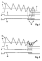
- FIG. 2 shows a schematic representation of a diagram with operating parameters for an example of a gasoline direct injection piezo device (GS piezo power amplifier and CJ 870) with a current waveform 40 with respect to a target current 42 I target , curves for a feedback signal 44 and a control signal 46, wherein a Piezoelectric actuator is loaded, if the control signal 46 is at level 1, and wherein no charge takes place, if the control signal 46 is at level 0.
- the control signals 46 shown here start at the same time and end at different times. If a curve for a control signal has the value 1 or 0, an associated feedback signal 44 has the value 0 or 1, respectively. Different opening times 48 for the feedback signal 44 are indicated in the diagram.
- the feedback signal 44 is set to inactive immediately after reaching the charging or discharging time at the opening time 48 and at the same time the cylinder select switch is opened. Depending on the switch-off time, residual energy may still be present in the transfer inductance. This leads to voltage jumps on highside lines of the piezoelectric actuator, which are assigned to an injector, which has a negative effect on the electromagnetic compatibility.
- FIG. 3 shows a schematic representation of a diagram for a possible embodiment of the inventive method for implementing a cylinder timing or a timing of a cylinder.
- FIG. 3 are several curves for a pulsed in this case waveform of a current 80 for a piezoelectric actuator with respect.
- the different operations differ in the length of the current pulse 105 (this is controlled by different long turn-on times: with increasing length of the control signal 88, the turn-on time increases).
- an additional current pulse 106 is added.
- the preceding sequence is repeated: a further current pulse is added. The whole thing is repeated until the control signal ends the process and a last timed current pulse is completed.
- the number of current pulses depends on the length of the control signal 88 and the target current limit 82.
- the diagram FIG. 3 also includes curves for a feedback signal 86 and control signal 88.
- a feedback signal 86 and a current 80 are respectively assigned to a control signal 88. If a control signal 88 has the value 1, an associated feedback signal 86 has the value 0. If a feedback signal 86 has the value 1, the associated control signal 88 has the value 0. A direction of the return signal 86 and the control signal 88 may also be reversed.
- the feedback signal 86 is "low-active", which means that the feedback signal 86 is active if it has the value 0, and that it is not active if it has the value 1.
- Time window 90 (T_ window), which begin at different times, shown, with only one of the time windows shown 90 is active.
- T_ window Time window 90
- multiple loading flanks for time windows 90 are shown one above the other.
- Each charging edge has a time window 90 and edge lengths of different lengths.
- current waveform 80 which may be a charging and / or discharging the piezoelectric actuator during the operating phase, to at multiple time points 92, 93, 94, the target current I below the 82nd
- the desired current I soll 82 is undershot , it is checked whether the time is within the time window 90 predetermined for this process with a length indicated by the first double arrow 96. Farther is indicated by the second double arrow 98, a time interval, from this time interval, the turn-on time for the timed current pulse is determined.
- the first three current pulses 101, 102, 103 fall below the target current 82 to one of the first three times 92 outside of the time window 90.
- a subsequent, fourth current pulse 104 by the current control on the desired current I soll 82 is provided.
- the fourth current pulse 104 falls below the target current I soll 82 at a fourth time 93, which is within the time window 90 (T_ window), in which case a subsequent, fifth current pulse 105 is added in a time-controlled manner. For this fifth current pulse 105 no more checking takes place.
- a turn-on time resolution is 125 ns at a system clock of 8 MHz.
- FIG. 4 An embodiment of an arrangement 120 according to the invention is shown in FIG. 4 shown.
- This arrangement comprises a current source 122, a measuring module 124 designed as an ammeter, a test module 126 and a switching module 128.
- a piezoactuator 130 When a piezoactuator 130 is operated, current is supplied to it by the current source 122.
- a current operating phase which may be a charge phase and / or a discharge phase of the piezoactuator, values of this provided current are measured by the measurement module 124 and provided to the test module 126.
- this test module 126 is checked whether the current falls below a target current and whether a time for falling below or outside the predetermined time window.
- a time-controlled current pulse is appended and then the current operating phase is ended, if the time is within the time window.
- the current and thus a subsequent current pulse will continue to be controlled via the setpoint current, if the time is outside the time window. In this case, the current operating phase is continued.
Description
Die Erfindung betrifft ein Verfahren zum Betreiben einer Endstufe für mindestens einen Piezoaktor, eine Anordnung zum Betreiben einer Endstufe für mindestens einen Piezoaktor, ein Computerprogramm und ein Computerprogrammprodukt.The invention relates to a method for operating an output stage for at least one piezoelectric actuator, an arrangement for operating an output stage for at least one piezoelectric actuator, a computer program and a computer program product.
In Steuergeräten für sog. Speichereinspritzungs- bzw. Common-Rail- oder CR-Piezo Systeme (DS) und Benzindirekteinspritz- bzw. BDE-Piezo Systeme (GS), die Piezoaktoren zum Beaufschlagen von Zylindern umfassen, wird auf Grundlage von systembedingten Anforderungen einer Zylinder-Auswahl (Zylinder-Select) zu unterschiedlichen Zeitpunkten am Ende eines Lade- bzw. Entladevorgangs ausgeschaltet. Bei BDE-Piezo Systemen wird die Zylinder-Auswahl exakt nach dem Ende der Lade- bzw. Entladezeit ausgeschaltet. Das erfolgt unabhängig davon, ob zu diesem Zeitpunkt noch Energie in einer Transferinduktivität einer Piezoendstufe vorhanden ist. Bei CR-Piezo Systemen wird nach dem Erreichen des Abschaltkriteriums, das durch die Zeit beim Laden und die Spannung beim Entladen bestimmt ist, die Zylinder-Auswahl erst ausgeschaltet, sobald in der Transferinduktivität nahezu keine Energie mehr vorhanden ist. Für BDE-Piezo Systeme ist üblicherweise bei Ansteuerungen vorgesehen, dass auf den Piezoaktor eine Ladung linear aufgebracht wird. Die Zylinder-Auswahl wird hierzu sofort nach dem Erreichen des Abschaltkriteriums, z. B. der Ladezeit, abgeschaltet, was jedoch für das Einhalten der Anforderungen bezüglich elektromagnetischer Verträglichkeit (EMV) einer Endstufe eines Steuergeräts ungünstig ist.In control units for so-called memory injection or common-rail or CR-piezo systems (DS) and gasoline direct injection or BDE piezo systems (GS), which include piezo actuators for loading cylinders, is based on system-related requirements of a cylinder Select (Cylinder Select) is turned off at different times at the end of a charge / discharge operation. With BDE piezo systems, the cylinder selection is switched off exactly after the end of the charging or discharging time. This occurs regardless of whether there is still energy in a transfer inductance of a piezo output stage at this time. In CR-Piezo systems, after reaching the shutdown criterion, which is determined by the time during charging and the voltage during discharging, the cylinder selection is switched off as soon as there is almost no energy left in the transfer inductance. For BDE piezo systems, it is usually provided in the case of actuations that a charge is applied linearly to the piezoactuator. The cylinder selection is for this purpose immediately after reaching the shutdown criterion, z. As the charging time, switched off, but this is unfavorable for the compliance with the requirements for electromagnetic compatibility (EMC) of an output stage of a controller.
Aus der Druckschrift
Die Erfindung betrifft ein Verfahren zum Betreiben einer Endstufe für mindestens einen Piezoaktor, der einem Zylinder zugeordnet und zum Antreiben eines Ventilelements dieses Zylinders ausgebildet ist. Bei dem Verfahren wird während einer Betriebsphase bei Unterschreiten eines durch den Piezoaktor fließenden Stroms unter einen Sollstrom überprüft, ob ein Zeitpunkt für das Unterschreiten außerhalb oder innerhalb eines Zeitfensters liegt. In Abhängigkeit davon, ob der Zeitpunkt bzgl. seiner Lage und/oder seines Beginns innerhalb eines typischerweise definierten Zeitfensters liegt, wird ein Kriterium für ein Ende der Betriebsphase bereitgestellt. Falls sich der Zeitpunkt außerhalb des Zeitfensters befindet, wird die Betriebsphase fortgesetzt und ein nachfolgender Strompuls bzw. Stromimpuls über den Sollstrom gesteuert. Der nachfolgende Strompuls wird alternativ über eine Einschaltzeit gesteuert, falls sich der Zeitpunkt innerhalb des Zeitfensters befindet. In diesem Fall wird die aktuelle Betriebsphase beendet, so dass eine neue Betriebsphase beginnen kann, bei der typischerweise ein neuer Sollstrom bereitgestellt wird. Die Anzahl der Strompulse hängt natürlich vom gewählten Betriebspunkt ab.The invention relates to a method for operating an output stage for at least one piezoactuator, which is assigned to a cylinder and designed to drive a valve element of this cylinder. In the method, it is checked during a phase of operation falls below a current flowing through the piezoelectric actuator current below a desired current, whether a time for falling below or outside a time window. Depending on whether the time with respect to its location and / or its beginning is within a typically defined time window, a criterion for an end of the operating phase is provided. If the time is outside the time window, the operating phase is continued and a subsequent current pulse or current pulse is controlled via the desired current. The subsequent current pulse is alternatively controlled for a turn-on time, if the time is within the time window. In this case, the current operating phase is terminated, so that a new operating phase can begin, in which typically a new setpoint current is provided. Of course, the number of current pulses depends on the selected operating point.
Unabhängig davon, wann die Betriebsphase beendet wird, wird dem Piezoaktor mit dem Strom eine Ladung linear aufgebracht. Falls sich der Zeitpunkt innerhalb des Zeitfensters befindet und ein üblicherweise zeitgesteuerter Strompuls bei Unterschreiten der Nullstromgrenze beendet wird, ist es auch möglich, dass ein Rückmeldesignal ausgeschaltet wird. Weiterhin kann ein Zylinder-Select-Schalter analog zu diesem Rückmeldesignal geschaltet werden. Dabei können eventuell auch mehrere zeitgesteuerte Strompulse, deren Anzahl fest definiert werden kann, abgesetzt werden. Außerdem kann in der nachfolgenden Betriebsphase ein weiterer Piezoaktor, der einem weiteren Zylinder zugeordnet ist, bestromt werden.Regardless of when the operating phase is terminated, a charge is applied linearly to the piezoelectric actuator with the current. If the time is within the time window and a usually time-controlled current pulse is terminated when the zero-current limit is undershot, it is also possible that a feedback signal is switched off. Furthermore, a cylinder select switch can be switched in analogy to this feedback signal. In doing so, possibly also several time-controlled current pulses, the number of which can be firmly defined, are discontinued. In addition, in the subsequent operating phase, a further piezoelectric actuator, which is assigned to a further cylinder, are energized.
Das Zeitfenster liegt üblicherweise am Ende einer Betriebszeit der Betriebsphase. Das Zeitfenster weist abhängig von einer Länge der Betriebsphase eine Länge von 0 bis 25 µs auf.The time window is usually at the end of an operating time of the operating phase. The time window has a length of 0 to 25 μs, depending on a length of the operating phase.
Die Einschaltzeit ist in einer Variante von einem Zeitintervall abhängig, das durch den Zeitpunkt für das Unterschreiten des Zeitfensters und dem Ende des Zeitfensters bzw. einem Zeitpunkt, bei dem das Zeitfenster in der Regel beendet ist, festgelegt wird.The switch-on time is dependent in a variant of a time interval, which is determined by the time for falling below the time window and the end of the time window or a time at which the time window is usually completed.
Die Länge des Zeitfensters wird einer anwendungsspezifischen integrierten Schaltung, die innerhalb eines Steuergeräts angeordnet sein kann, über eine serielle periphere Schnittstelle vorgegeben.The length of the time window is given to an application-specific integrated circuit, which can be arranged within a control device, via a serial peripheral interface.
Das Verfahren kann für eine als Ladephase ausgebildete Betriebsphase, bei der der Piezoaktor geladen wird und/oder für eine als Entladephase ausgebildete Betriebsphase, bei der der Piezoaktor entladen wird, durchgeführt werden.The method can be carried out for an operating phase designed as a charging phase in which the piezoactuator is charged and / or for an operating phase designed as a discharge phase in which the piezoactuator is discharged.
Die Erfindung betrifft weiterhin eine Anordnung zum Betreiben einer Endstufe für mindestens einen Piezoaktor. Dabei ist die Anordnung dazu ausgebildet, während einer Betriebsphase der Endstufe einen dem Piezoaktor bereitgestellten Strom zu messen und zu überprüfen, zu welchem Zeitpunkt der Strom einen Sollstrom unterschreitet und ob dieser Zeitpunkt außerhalb oder innerhalb eines Zeitfensters liegt. Die Anordnung ist auch dazu ausgebildet, die Betriebsphase fortzusetzen und einen nachfolgenden Strompuls bzw. Stromimpuls über den Sollstrom zu steuern, falls sich der Zeitpunkt außerhalb des Zeitfensters befindet. Außerdem ist die Anordnung dazu ausgebildet, den nachfolgenden Strompuls alternativ über eine Einschaltzeit zu steuern, falls sich der Zeitpunkt innerhalb des Zeitfensters befindet.The invention further relates to an arrangement for operating an output stage for at least one piezoelectric actuator. In this case, the arrangement is designed to measure a current provided to the piezoelectric actuator during an operating phase of the output stage and to check at which time the current falls below a nominal current and whether this time is outside or within a time window. The arrangement is also designed to continue the operating phase and to control a subsequent current pulse or current pulse over the desired current, if the time is outside the time window. In addition, the arrangement is designed to control the subsequent current pulse alternatively over a switch-on time, if the time is within the time window.
Die Anordnung kann mindestens ein Messmodul zum Messen des Stroms, mindestens ein Prüfmodul zum überprüfen, ob der Zeitpunkt innerhalb oder außerhalb des Fensters liegt sowie mindestens ein Schaltmodul zum stromgesteuerten oder zeitgesteuerten Schalten des Stroms und somit des Strompulses aufweisen.The arrangement can have at least one measuring module for measuring the current, at least one test module for checking whether the time is inside or outside the window and at least one switching module for current-controlled or timed switching of the current and thus of the current pulse.
Die beschriebene Anordnung ist dazu ausgebildet, sämtliche Schritte des vorgestellten Verfahrens durchzuführen. Dabei können einzelne Schritte dieses Verfahrens auch von einzelnen Modulen der Anordnung durchgeführt werden. Weiterhin können Funktionen der Anordnung oder Funktionen von einzelnen Modulen der Anordnung als Schritte des Verfahrens umgesetzt werden. Außerdem ist es möglich, dass Schritte des Verfahrens als Funktionen einzelner Module der Anordnung oder der gesamten Anordnung realisiert werden.The arrangement described is designed to carry out all the steps of the presented method. In this case, individual steps of this method can also be carried out by individual modules of the arrangement. Furthermore, functions of the arrangement or functions of individual modules of the arrangement can be implemented as steps of the method. In addition, it is possible that steps of the method are realized as functions of individual modules of the arrangement or of the entire arrangement.
Die Erfindung betrifft weiterhin ein Computerprogramm mit Programmcodemitteln, um alle Schritte eines beschriebenen Verfahrens durchzuführen, wenn das Computerprogramm auf einem Computer oder einer entsprechenden Recheneinheit, insbesondere in einer erfindungsgemäßen Anordnung, ausgeführt wird.The invention further relates to a computer program with program code means in order to perform all the steps of a described method when the computer program is executed on a computer or a corresponding arithmetic unit, in particular in an arrangement according to the invention.
Das erfindungsgemäße Computerprogrammprodukt mit Programmcodemitteln, die auf einem computerlesbaren Datenträger gespeichert sind, ist zum Durchführen aller Schritte eines beschriebenen Verfahrens ausgebildet, wenn das Computerprogramm auf einem Computer oder einer entsprechenden Recheneinheit, insbesondere in einer erfindungsgemäßen Anordnung, ausgeführt wird.The computer program product according to the invention with program code means which are stored on a computer-readable data carrier is designed to carry out all the steps of a described method when the computer program is executed on a computer or a corresponding arithmetic unit, in particular in an arrangement according to the invention.
Mit der Erfindung werden die Vorgehensweisen, die bei Speichereinspritzungs-Piezo Systemen (DS) und Benzindirekteinspritz-Piezo Systemen (GS) zur Anwendung kommen, kombiniert, so dass ein Zylinder-Timing bzw. eine zeitliche Steuerung zur Beaufschlagung von Zylindern eines Verbrennungsmotors mit Piezoaktoren umgesetzt werden kann. Es ist dabei u. a. möglich, eine lineare Aufbringung der Ladung auf den Piezoaktor bereitzustellen, ohne dabei das Verhalten bzgl. der elektromagnetischen Verträglichkeit durch eine hohe Restenergie in einer bspw. als Drossel ausgebildeten Transferinduktivität des Piezoaktors negativ zu beeinflussen.The present invention combines the techniques used in accumulator-type piezo (DS) systems and gasoline direct injection piezo (GS) systems to implement cylinder timing for actuation of cylinders of internal combustion engines with piezo actuators can be. It is u. a. possible to provide a linear application of the charge on the piezoelectric actuator, without negatively influencing the behavior with respect to the electromagnetic compatibility by a high residual energy in a transfer inductance of the piezoactuator, for example, designed as a choke.
Bei einer Ausführung des Verfahrens wird während mindestens einer Betriebsphase, bei der es sich um die Lade- und/oder Entladephase handeln kann, bei jedem Unterschreiten der Stromgrenze für einen Sollstrom Isoll geprüft, ob der Zeitpunkt innerhalb eines definierten Zeitfensters "T_Fenster" liegt. Das Zeitfenster liegt üblicherweise am Ende der Lade- bzw. Entladephase und wird über eine serielle periphere Schnittstelle (SPI) einer anwendungsspezifischen integrierten Schaltung (ASIC, Application Specific Integrated Circuit) der Endstufen vorgegeben. Das Fenster kann für seine Länge z. B. einen Wert im Bereich von 0 bis 25 µs aufweisen, was üblicherweise circa 10 %, maximal bis zu 25 % einer gesamten Länge des Betriebszyklus, der in der Regel zwischen 100 µs... 200 µs andauern kann, entspricht. Üblicherweise weist der für den Piezoaktor vorgesehene Strom ein weitgehend zickzackförmiges Profil auf, so dass der Strom während einer der genannten Betriebsphasen die Grenzen für den Sollstrom ISoll ggf. mehrmals unterschreiten kann, bis der Zeitpunkt für das Unterschreiten des Sollstroms innerhalb des Zeitfensters erreicht ist.In one embodiment of the method, at least one operating phase, which may be the charging and / or discharging phase, is checked at each falling below the current limit for a nominal current I soll , if the time is within a defined time window "T_Fenster". The time window is usually at the end of the charging or discharging phase and is an application-specific integrated via a serial peripheral interface (SPI) Circuit (ASIC, Application Specific Integrated Circuit) of the final stages specified. The window can be z. Example, have a value in the range of 0 to 25 microseconds, which is usually about 10%, up to a maximum of 25% of a total length of the operating cycle, which can usually last between 100 microseconds ... 200 microseconds corresponds. Usually, the current provided for the piezoelectric actuator has a largely zigzag-shaped profile, so that the current during one of the mentioned operating phases may fall below the limits for the desired current I desired several times, until the time for falling below the desired current within the time window has been reached.
Ist zum Überprüfungszeitpunkt das Zeitfenster noch nicht erreicht, so wird der nachfolgende Strompuls, wie zuvor durchgeführt, über den Sollstrom Isoll gesteuert. Sobald sich der Überprüfungszeitpunkt innerhalb des Zeitfensters befindet, wird der nachfolgende Strompuls über die Einschaltzeit gesteuert. Die Einschaltzeit ist u. a. von der Zeitdauer abhängig, die sich von dem Zeitpunkt, ab der die Stromgrenze für den Sollstrom Isoll unterschritten wird, bis zum Ende des Zeitfensters erstreckt, was zugleich einem Ende der Lade- bzw. Entladeflanke entspricht. Je weiter der Zeitpunkt für ein Unterschreiten des Sollstroms Isoll vom Ende des Zeitfensters "T_Fenster" entfernt liegt, umso länger wird die Einschaltzeit, so dass die Einschaltzeit zu der genannten Zeitdauer proportional sein kann.If the time window has not yet been reached at the time of checking, then the subsequent current pulse, as carried out previously, is controlled via the setpoint current I soll . Once the verification time is within the time window, the subsequent current pulse is controlled over the turn-on time. The switch-on time depends inter alia on the time duration which extends from the time from which the current limit for the setpoint current I soll is undershot to the end of the time window, which at the same time corresponds to an end of the charging or discharging flank. The further the time point for falling short of the setpoint current I soll from the end of the time window "T_ window", the longer the switch-on time, so that the switch-on time can be proportional to the stated time duration.
Durch diese Maßnahme ergibt sich, dass sich mit einer längeren oder kürzeren Ladezeit bzw. Entladezeit eine entsprechend größere oder kleinere Ladung auf dem Piezoaktor einstellt und gleichzeitig der Zylinder-Select-Schalter analog zum Rückmeldesignal immer erst bei einer definiert kleinen Restenergie in der Transferinduktivität bzw. der Drossel zur Beaufschlagung des Piezoaktors ausgeschaltet wird. Bei der bisherigen Lösung für Speichereinspritzungs-Piezo Systemen ergibt sich abhängig von dem Zeitpunkt, der ein Ende der Lade- bzw. Entladezeit festlegt, und dem Stromverlauf, üblicherweise in Abhängigkeit des Zeitpunkts, zu dem der Sollstrom Isoll überschritten und eine Nullstromgrenze noch nicht unterschritten ist, ein sog. Totzeitpunkt, während dem die aufgebrachte Ladung zum vorangegangenen Arbeitspunkt trotz verlängerter oder verkürzter Lade- bzw. Entladezeit nicht verändert wird. Dies führt zu einem nichtlinearen Zusammenhang zwischen der Lade- bzw. Entladezeit und der aufgebrachten bzw. abgeführten Ladung.This measure results in a correspondingly larger or smaller charge being set on the piezoactuator with a longer or shorter charging time or discharging time and, at the same time, the cylinder select switch being analogous to the acknowledgment signal only at a defined minimum residual energy in the transfer inductance or the throttle is switched off to act on the piezoelectric actuator. In the previous solution for memory injection piezo systems results depending on the time that defines an end of the charging or discharging time, and the current curve, usually in dependence on the time at which the target current I should be exceeded and not fallen below a zero current limit is, a so-called dead time point during which the applied charge to the previous operating point is not changed despite prolonged or shortened charging or discharging time. This leads to a non-linear relationship between the charging or discharging time and the applied or discharged charge.
Das Verfahren kann bspw. in einem Schaltkreis (ASIC) für eine DGS Piezo-Endstufe realisiert und weiterhin in allen DS-Piezo-Anlagen für Speichereinspritzung und GS-Piezo-Anlagen für Benzindirekteinspritzungen eingesetzt werden.The process can be implemented, for example, in a circuit (ASIC) for a DGS piezo power amplifier and continue to be used in all DS piezo systems for accumulator injection and GS piezo systems for gasoline direct injection.
Weitere Vorteile und Ausgestaltungen der Efindung ergeben sich aus der Beschreibung und der beiliegenden Zeichnung.Further advantages and embodiments of the invention will become apparent from the description and the accompanying drawings.
Es versteht sich, dass die voranstehend genannten und die nachstehend noch zu erläuternden Merkmale nicht nur in der jeweils angegebenen Kombination, sondern auch in anderen Kombinationen oder in Alleinstellung verwendbar sind, ohne den Rahmen der vorliegenden Erfindung zu verlassen.It is understood that the features mentioned above and those yet to be explained below can be used not only in the respectively specified combination but also in other combinations or alone, without departing from the scope of the present invention.
Beispiele aus dem Stand der Technik Finden sich in
-
Figur 1 zeigt in schematischer Darstellung ein Diagramm mit Betriebsparametern, die bei Betrieb einer Speichereinspritzungs-Piezoanordnung (DS) auftreten.FIG. 1 shows a schematic representation of a diagram with operating parameters that occur during operation of a memory injection piezoelectric device (DS). -
Figur 2 zeigt in schematischer Darstellung ein Diagramm mit Betriebsparametern, die sich beim Betrieb einer Benzindirekteinspritz-Piezovorrichtung (GS) ergeben.FIG. 2 shows a schematic representation of a diagram with operating parameters that result in the operation of a gasoline direct injection piezoelectric device (GS). -
Figur 3 zeigt ein Diagramm für Betriebsparameter, die sich bei Umsetzung einer Ausführungsform des erfindungsgemäßen Verfahrens für eine Ausführungsform einer erfindungsgemäßen Anordnung ergeben.FIG. 3 shows a diagram for operating parameters, resulting in implementation of an embodiment of the inventive method for an embodiment of an inventive arrangement. -
Figur 4 zeigt in schematischer Darstellung eine Ausführungsform einer erfindungsgemäßen Anordnung.FIG. 4 shows a schematic representation of an embodiment of an arrangement according to the invention.
Die Erfindung ist anhand von Ausführungsformen in den Zeichnungen schematisch dargestellt und wird nachfolgend unter Bezugnahme auf die Zeichnungen ausführlich beschriebenThe invention is schematically illustrated by means of embodiments in the drawings and will be described in detail below with reference to the drawings
Die Figuren werden zusammenhängend und übergreifend beschrieben, gleiche Bezugszeichen bezeichnen gleiche Komponenten.The figures are described in a coherent and comprehensive manner, like reference numerals designate like components.
Durch diese Maßnahme wird das Verhalten hinsichtlich der elektromagnetischen Verträglichkeit begünstigt, da das Rückmeldesignal 8 erst abgeschaltet und somit auch der Zylinder-Select-Schalter ausgeschalter wird, sobald der Strom 2 die Nullstromgrenze 6 unterschritten hat und somit nahezu den Wert 0 erreicht hat. Außerdem ist ein nichtlinearer Zusammenhang zwischen der Lade- bzw. Entladezeit und einer aufgebrachten bzw. abgeführten Ladung durch einen Totzeitpunkt, während dem der Sollstrom 4 Isoll bei einem letzten Strompuls überschritten und die Nullstromgrenze 6 noch nicht erreicht ist, gegeben. Eine Bedingung für die Totzeit ist, dass der Sollstrom 4 Isoll überschritten ist und die Nullstromgrenze noch nicht unterschritten ist. Bei manchen gestrichelten Steuersignalen 10 mit unterschiedlichen Enden 12 verändert sich der Stromverlauf nicht, d. h. hier ergibt sich keine Änderungen der Ladung.By this measure, the behavior is favored in terms of electromagnetic compatibility, since the feedback signal 8 is turned off and thus also the cylinder select switch is switched off when the current 2 has fallen below the zero current limit 6 and thus has almost reached the
Dabei ergibt sich eine lineare Ladungsaufbringung in Abhängigkeit der Lade- bzw. Entladezeit. Das Rückmeldesignal 44 wird sofort nach Erreichen der Lade- bzw. Entladezeit zum Öffnungszeitpunkt 48 auf nicht aktiv gesetzt und gleichzeitig der Zylinder-Select-Schalter geöffnet. Je nach Abschaltzeitpunkt kann noch Restenergie in der Transferinduktivität vorhanden sein. Dies führt zu Spannungssprüngen an Highside-Leitungen des Piezoaktors, die einem Injektor zugeordnet sind, was sich negativ auf die elektromagnetische Verträglichkeit auswirkt.This results in a linear charge application as a function of the charging or discharging time. The
In dem Diagramm aus
Das Diagramm aus
Für den hier gepulsten bzw. getakteten Stromverlauf 80 wird während der Betriebsphase, bei der es sich um eine Lade- und/oder Entladephase des Piezoaktors handeln kann, zu mehreren Zeitpunkten 92, 93, 94 der Sollstrom Isoll 82 unterschritten. Bei jedem Unterschreiten des Sollstroms Isoll 82 wird überprüft, ob sich der Zeitpunkt innerhalb des für diesen Vorgang vorgegebenen Zeitfensters 90 mit einer durch den ersten Doppelpfeil 96 angedeuteten Länge befindet. Weiterhin ist durch den zweiten Doppelpfeil 98 ein Zeitintervall angedeutet, aus diesem Zeitintervall wird die Einschaltzeit für den zeitgesteuerten Strompuls ermittelt.For the pulsed or cycled here
Bei den ersten Vorgängen (5 Strompuls ohne Strompuls 106) unterschreiten die ersten drei Strompulse 101, 102, 103 den Sollstrom 82 zu einem der ersten drei Zeitpunkte 92 außerhalb des Zeitfensters 90. In diesen Fällen wird ein nachfolgender, vierter Strompuls 104 durch die Stromregelung auf den Sollstrom Isoll 82 bereitgestellt. Der vierte Strompuls 104 unterschreitet den Sollstrom Isoll 82 zu einem vierten Zeitpunkt 93, der sich innerhalb des Zeitfensters 90 (T_Fenster) befindet, in diesem Fall wird ein nachfolgender, fünfter Strompuls 105 zeitgesteuert angehängt. Für diesen fünften Strompuls 105 findet keine Überprüfung mehr statt. Eine Auflösung der Einschaltzeit beträgt 125 ns bei einem Systemtakt von 8 MHz.In the first operations (5 current pulse without current pulse 106), the first three
Eine Ausführungsform einer erfindungsgemäßen Anordnung 120 ist in
Claims (10)
- Method for operating an output stage for at least one piezoactuator (130), in which, when a current (80) for the piezoactuator (130) falls below a setpoint current (82) during an operating phase, a check is made to determine whether a time (92, 93, 94) at which the current falls below a setpoint current is outside or within a time window (90), with a subsequent current pulse (101, 102, 103, 104, 105, 106) being controlled by means of the setpoint current (82) if the time (92, 93, 94) is outside the time window (90), and with the subsequent current pulse (101, 102, 103, 104, 105, 106) being controlled by means of a switch-on time if the time (92, 93, 94) is within the time window (90).
- Method according to Claim 1, in which a charge is linearly applied to the piezoactuator (130) with the current (80).
- Method according to Claim 1 or 2, in which a response signal (86) is switched off and analogously a cylinder select switch is switched off if the time (92, 93, 94) is within the time window (90) and a time-controlled current pulse (101, 102, 103, 104, 105, 106) is terminated when the current falls below a zero current limit (84), it also being possible for a plurality of time-controlled current pulses to possibly be dropped, the number of said current pulses being fixedly defined.
- Method according to one of the preceding claims, in which the time window (90) is at the end of an operating time of the operating phase.
- Method according to one of the preceding claims, in which the switch-on time is dependent on a time interval (98) which is defined by the time (92, 93, 94) at which the current falls below a setpoint current (82) and the end of the time window (90).
- Method according to one of the preceding claims, in which a length of the time window (90) of a use-specific integrated circuit is prespecified by means of a serial peripheral interface.
- Method according to one of the preceding claims, which is carried out for an operating phase which is in the form of a charging phase and/or for an operating phase which is in the form of a discharging phase.
- Arrangement for operating an output stage for at least one piezoactuator (130) which is designed to measure a current (80) for the piezoactuator (130) during an operating phase of the output stage, and to check the time (92, 93, 94) at which the current (80) falls below a setpoint current (82) and whether this time (92, 93, 94) is outside or within a time window (90), with the arrangement being designed to control a subsequent current pulse (101, 102, 103, 104, 105) by means of the setpoint current (82) if the time (92, 93, 94) is outside the time window (90), and to control the subsequent current pulse (101, 102, 103, 104, 105) by means of a switch-on time if the time (92, 93, 94) is within the time window (90).
- Computer program having program code means, in order to carry out all the steps of a method according to one of Claims 1 to 7 when the computer program is run on a computer or a corresponding computer unit, in particular in an arrangement (120) according to Claim 8.
- Computer program product having program code means which are stored on a computer-readable data storage medium, in order to carry out all the steps of a method according to one of Claims 1 to 7 when the computer program is run on a computer or a corresponding computer unit, in particular in an arrangement (120) according to Claim 8.
Applications Claiming Priority (2)
| Application Number | Priority Date | Filing Date | Title |
|---|---|---|---|
| DE200910001077 DE102009001077A1 (en) | 2009-02-23 | 2009-02-23 | Method for operating an output stage for at least one piezoelectric actuator |
| PCT/EP2010/050034 WO2010094516A1 (en) | 2009-02-23 | 2010-01-05 | Method for operating a final stage for at least one piezoactuator |
Publications (2)
| Publication Number | Publication Date |
|---|---|
| EP2399016A1 EP2399016A1 (en) | 2011-12-28 |
| EP2399016B1 true EP2399016B1 (en) | 2012-11-21 |
Family
ID=42114870
Family Applications (1)
| Application Number | Title | Priority Date | Filing Date |
|---|---|---|---|
| EP10700511A Active EP2399016B1 (en) | 2009-02-23 | 2010-01-05 | Method for operating a final stage for at least one piezoactuator |
Country Status (5)
| Country | Link |
|---|---|
| US (1) | US8952597B2 (en) |
| EP (1) | EP2399016B1 (en) |
| CN (1) | CN102325984B (en) |
| DE (1) | DE102009001077A1 (en) |
| WO (1) | WO2010094516A1 (en) |
Families Citing this family (2)
| Publication number | Priority date | Publication date | Assignee | Title |
|---|---|---|---|---|
| DE102013214832A1 (en) | 2013-07-30 | 2015-02-05 | Robert Bosch Gmbh | Method for operating an output stage for at least one piezoelectric actuator |
| DE102014203538A1 (en) * | 2014-02-27 | 2015-08-27 | Robert Bosch Gmbh | Method for noise-reducing control of switchable valves, in particular injection valves of an internal combustion engine of a motor vehicle |
Family Cites Families (10)
| Publication number | Priority date | Publication date | Assignee | Title |
|---|---|---|---|---|
| DE19644521A1 (en) | 1996-10-25 | 1998-04-30 | Siemens Ag | Method and device for controlling a capacitive actuator |
| WO1999017009A1 (en) | 1997-09-29 | 1999-04-08 | Siemens Aktiengesellschaft | Method for controlling an electro mechanical regulating device |
| US6292345B1 (en) | 1998-09-02 | 2001-09-18 | Siemens Aktiengesellschaft | Method for controlling an electromechanical actuator |
| DE19845037C2 (en) * | 1998-09-30 | 2000-11-30 | Siemens Ag | Method and arrangement for controlling a capacitive actuator |
| DE10247988A1 (en) * | 2002-10-15 | 2004-04-29 | Robert Bosch Gmbh | Method and device for controlling a piezo actuator |
| DE10359675B3 (en) | 2003-12-18 | 2005-07-07 | Volkswagen Mechatronic Gmbh & Co. Kg | Method and device for controlling a valve and method and device for controlling a pump-nozzle device with the valve |
| GB0610225D0 (en) | 2006-05-23 | 2006-07-05 | Delphi Tech Inc | Method of controlling a piezoelectric actuator |
| US7856964B2 (en) * | 2006-05-23 | 2010-12-28 | Delphi Technologies Holding S.Arl | Method of controlling a piezoelectric actuator |
| EP1923559B1 (en) | 2006-11-14 | 2009-10-07 | Delphi Technologies, Inc. | A method of controlling a piezoelectric actuator |
| DE102007014326A1 (en) * | 2007-03-26 | 2008-10-02 | Robert Bosch Gmbh | Method and device for charging a capacitive element |
-
2009
- 2009-02-23 DE DE200910001077 patent/DE102009001077A1/en not_active Withdrawn
-
2010
- 2010-01-05 US US13/138,397 patent/US8952597B2/en not_active Expired - Fee Related
- 2010-01-05 EP EP10700511A patent/EP2399016B1/en active Active
- 2010-01-05 CN CN201080008661.9A patent/CN102325984B/en not_active Expired - Fee Related
- 2010-01-05 WO PCT/EP2010/050034 patent/WO2010094516A1/en active Application Filing
Also Published As
| Publication number | Publication date |
|---|---|
| EP2399016A1 (en) | 2011-12-28 |
| DE102009001077A1 (en) | 2010-08-26 |
| CN102325984B (en) | 2014-06-18 |
| WO2010094516A1 (en) | 2010-08-26 |
| CN102325984A (en) | 2012-01-18 |
| US8952597B2 (en) | 2015-02-10 |
| US20120032556A1 (en) | 2012-02-09 |
Similar Documents
| Publication | Publication Date | Title |
|---|---|---|
| DE102008023373B4 (en) | Method of controlling an injector, fuel injection system and internal combustion engine | |
| DE102011075732B4 (en) | Control method for an injection valve and injection system | |
| DE102013206600B4 (en) | Injection system for injecting fuel into an internal combustion engine and control method for such an injection system | |
| WO2011131467A2 (en) | Method for operating an internal combustion engine in which a solenoid valve for injecting fuel is actuated | |
| WO2009135824A1 (en) | Method and apparatus for controlling of a servo-drive | |
| DE102010022910B4 (en) | Method and device for operating an injection valve | |
| WO2000004590A1 (en) | Method and device for controlling at least one capacitive actuator | |
| DE19652809C1 (en) | Method and device for controlling at least one capacitive actuator | |
| EP2399016B1 (en) | Method for operating a final stage for at least one piezoactuator | |
| DE102005046933B4 (en) | Method for controlling a piezo-actuated injection valve | |
| DE102005016279B4 (en) | Circuit arrangement and method for actuating an up and dischargeable, electromechanical actuator | |
| EP2020044B1 (en) | Device for actuating at least one piezo-electric actuating drive of an injection nozzle for an internal combustion engine | |
| EP1375882B2 (en) | Method for operating a combustion engine, in particular a motor vehicle | |
| EP1400675B1 (en) | Method and device for controlling at least two piezo-actuators | |
| DE10305525A1 (en) | Method and device for adapting the pressure wave correction in a high-pressure injection system of a motor vehicle while driving | |
| DE102007058540B4 (en) | Method and apparatus for charging and discharging a piezoelectric element | |
| DE102008044741B4 (en) | Method and control device for controlling an injector | |
| DE102004053349A1 (en) | Fuel injector controlling method for internal combustion engine, involves actuating fuel injection by supplying control pulse to actuator, and supplying conditioning pulse to actuator before fuel injection, during injecting interval | |
| DE10106170A1 (en) | Method for controlling an injection valve with piezo-actuator, involves applying non-null voltage different from first voltage, but of same sign, to close/open valve after applying first voltage to open/close it | |
| WO2016165892A1 (en) | Method for operating a directly actuated piezo-controlled injection valve | |
| WO2013110522A1 (en) | Method and control device for charging or discharging a piezo-electric actuator | |
| DE102012222097A1 (en) | Method for operating fuel injection valve for internal combustion engine e.g. diesel engine, involves injecting fuel into chamber, where value characterizing energy for controlling actuator is formed based on injection parameters | |
| DE102014222719A1 (en) | Method for discharging a piezo actuator | |
| DE102017207821A1 (en) | Method of operating a piezoelectric element, apparatus for carrying out the method, control unit program and control unit program product | |
| DE102013214832A1 (en) | Method for operating an output stage for at least one piezoelectric actuator |
Legal Events
| Date | Code | Title | Description |
|---|---|---|---|
| PUAI | Public reference made under article 153(3) epc to a published international application that has entered the european phase |
Free format text: ORIGINAL CODE: 0009012 |
|
| 17P | Request for examination filed |
Effective date: 20110923 |
|
| AK | Designated contracting states |
Kind code of ref document: A1 Designated state(s): AT BE BG CH CY CZ DE DK EE ES FI FR GB GR HR HU IE IS IT LI LT LU LV MC MK MT NL NO PL PT RO SE SI SK SM TR |
|
| DAX | Request for extension of the european patent (deleted) | ||
| GRAP | Despatch of communication of intention to grant a patent |
Free format text: ORIGINAL CODE: EPIDOSNIGR1 |
|
| GRAS | Grant fee paid |
Free format text: ORIGINAL CODE: EPIDOSNIGR3 |
|
| GRAA | (expected) grant |
Free format text: ORIGINAL CODE: 0009210 |
|
| AK | Designated contracting states |
Kind code of ref document: B1 Designated state(s): AT BE BG CH CY CZ DE DK EE ES FI FR GB GR HR HU IE IS IT LI LT LU LV MC MK MT NL NO PL PT RO SE SI SK SM TR |
|
| REG | Reference to a national code |
Ref country code: GB Ref legal event code: FG4D Free format text: NOT ENGLISH |
|
| REG | Reference to a national code |
Ref country code: CH Ref legal event code: EP |
|
| REG | Reference to a national code |
Ref country code: AT Ref legal event code: REF Ref document number: 585207 Country of ref document: AT Kind code of ref document: T Effective date: 20121215 |
|
| REG | Reference to a national code |
Ref country code: IE Ref legal event code: FG4D Free format text: LANGUAGE OF EP DOCUMENT: GERMAN |
|
| REG | Reference to a national code |
Ref country code: DE Ref legal event code: R096 Ref document number: 502010001685 Country of ref document: DE Effective date: 20130117 |
|
| REG | Reference to a national code |
Ref country code: NL Ref legal event code: VDEP Effective date: 20121121 |
|
| REG | Reference to a national code |
Ref country code: LT Ref legal event code: MG4D |
|
| PG25 | Lapsed in a contracting state [announced via postgrant information from national office to epo] |
Ref country code: LT Free format text: LAPSE BECAUSE OF FAILURE TO SUBMIT A TRANSLATION OF THE DESCRIPTION OR TO PAY THE FEE WITHIN THE PRESCRIBED TIME-LIMIT Effective date: 20121121 Ref country code: ES Free format text: LAPSE BECAUSE OF FAILURE TO SUBMIT A TRANSLATION OF THE DESCRIPTION OR TO PAY THE FEE WITHIN THE PRESCRIBED TIME-LIMIT Effective date: 20130304 Ref country code: FI Free format text: LAPSE BECAUSE OF FAILURE TO SUBMIT A TRANSLATION OF THE DESCRIPTION OR TO PAY THE FEE WITHIN THE PRESCRIBED TIME-LIMIT Effective date: 20121121 Ref country code: NO Free format text: LAPSE BECAUSE OF FAILURE TO SUBMIT A TRANSLATION OF THE DESCRIPTION OR TO PAY THE FEE WITHIN THE PRESCRIBED TIME-LIMIT Effective date: 20130221 Ref country code: SE Free format text: LAPSE BECAUSE OF FAILURE TO SUBMIT A TRANSLATION OF THE DESCRIPTION OR TO PAY THE FEE WITHIN THE PRESCRIBED TIME-LIMIT Effective date: 20121121 Ref country code: HR Free format text: LAPSE BECAUSE OF FAILURE TO SUBMIT A TRANSLATION OF THE DESCRIPTION OR TO PAY THE FEE WITHIN THE PRESCRIBED TIME-LIMIT Effective date: 20121121 |
|
| PG25 | Lapsed in a contracting state [announced via postgrant information from national office to epo] |
Ref country code: PT Free format text: LAPSE BECAUSE OF FAILURE TO SUBMIT A TRANSLATION OF THE DESCRIPTION OR TO PAY THE FEE WITHIN THE PRESCRIBED TIME-LIMIT Effective date: 20130321 Ref country code: LV Free format text: LAPSE BECAUSE OF FAILURE TO SUBMIT A TRANSLATION OF THE DESCRIPTION OR TO PAY THE FEE WITHIN THE PRESCRIBED TIME-LIMIT Effective date: 20121121 Ref country code: SI Free format text: LAPSE BECAUSE OF FAILURE TO SUBMIT A TRANSLATION OF THE DESCRIPTION OR TO PAY THE FEE WITHIN THE PRESCRIBED TIME-LIMIT Effective date: 20121121 Ref country code: PL Free format text: LAPSE BECAUSE OF FAILURE TO SUBMIT A TRANSLATION OF THE DESCRIPTION OR TO PAY THE FEE WITHIN THE PRESCRIBED TIME-LIMIT Effective date: 20121121 Ref country code: GR Free format text: LAPSE BECAUSE OF FAILURE TO SUBMIT A TRANSLATION OF THE DESCRIPTION OR TO PAY THE FEE WITHIN THE PRESCRIBED TIME-LIMIT Effective date: 20130222 |
|
| BERE | Be: lapsed |
Owner name: ROBERT BOSCH G.M.B.H. Effective date: 20130131 |
|
| PG25 | Lapsed in a contracting state [announced via postgrant information from national office to epo] |
Ref country code: DK Free format text: LAPSE BECAUSE OF FAILURE TO SUBMIT A TRANSLATION OF THE DESCRIPTION OR TO PAY THE FEE WITHIN THE PRESCRIBED TIME-LIMIT Effective date: 20121121 Ref country code: BG Free format text: LAPSE BECAUSE OF FAILURE TO SUBMIT A TRANSLATION OF THE DESCRIPTION OR TO PAY THE FEE WITHIN THE PRESCRIBED TIME-LIMIT Effective date: 20130221 Ref country code: EE Free format text: LAPSE BECAUSE OF FAILURE TO SUBMIT A TRANSLATION OF THE DESCRIPTION OR TO PAY THE FEE WITHIN THE PRESCRIBED TIME-LIMIT Effective date: 20121121 Ref country code: CZ Free format text: LAPSE BECAUSE OF FAILURE TO SUBMIT A TRANSLATION OF THE DESCRIPTION OR TO PAY THE FEE WITHIN THE PRESCRIBED TIME-LIMIT Effective date: 20121121 Ref country code: SK Free format text: LAPSE BECAUSE OF FAILURE TO SUBMIT A TRANSLATION OF THE DESCRIPTION OR TO PAY THE FEE WITHIN THE PRESCRIBED TIME-LIMIT Effective date: 20121121 |
|
| PG25 | Lapsed in a contracting state [announced via postgrant information from national office to epo] |
Ref country code: NL Free format text: LAPSE BECAUSE OF FAILURE TO SUBMIT A TRANSLATION OF THE DESCRIPTION OR TO PAY THE FEE WITHIN THE PRESCRIBED TIME-LIMIT Effective date: 20121121 Ref country code: MC Free format text: LAPSE BECAUSE OF NON-PAYMENT OF DUE FEES Effective date: 20130131 Ref country code: RO Free format text: LAPSE BECAUSE OF FAILURE TO SUBMIT A TRANSLATION OF THE DESCRIPTION OR TO PAY THE FEE WITHIN THE PRESCRIBED TIME-LIMIT Effective date: 20121121 |
|
| PLBE | No opposition filed within time limit |
Free format text: ORIGINAL CODE: 0009261 |
|
| STAA | Information on the status of an ep patent application or granted ep patent |
Free format text: STATUS: NO OPPOSITION FILED WITHIN TIME LIMIT |
|
| REG | Reference to a national code |
Ref country code: IE Ref legal event code: MM4A |
|
| 26N | No opposition filed |
Effective date: 20130822 |
|
| PG25 | Lapsed in a contracting state [announced via postgrant information from national office to epo] |
Ref country code: BE Free format text: LAPSE BECAUSE OF NON-PAYMENT OF DUE FEES Effective date: 20130131 |
|
| REG | Reference to a national code |
Ref country code: DE Ref legal event code: R097 Ref document number: 502010001685 Country of ref document: DE Effective date: 20130822 |
|
| PG25 | Lapsed in a contracting state [announced via postgrant information from national office to epo] |
Ref country code: IE Free format text: LAPSE BECAUSE OF NON-PAYMENT OF DUE FEES Effective date: 20130105 |
|
| PG25 | Lapsed in a contracting state [announced via postgrant information from national office to epo] |
Ref country code: MT Free format text: LAPSE BECAUSE OF FAILURE TO SUBMIT A TRANSLATION OF THE DESCRIPTION OR TO PAY THE FEE WITHIN THE PRESCRIBED TIME-LIMIT Effective date: 20121121 |
|
| REG | Reference to a national code |
Ref country code: CH Ref legal event code: PL |
|
| PG25 | Lapsed in a contracting state [announced via postgrant information from national office to epo] |
Ref country code: LI Free format text: LAPSE BECAUSE OF NON-PAYMENT OF DUE FEES Effective date: 20140131 Ref country code: CH Free format text: LAPSE BECAUSE OF NON-PAYMENT OF DUE FEES Effective date: 20140131 |
|
| PG25 | Lapsed in a contracting state [announced via postgrant information from national office to epo] |
Ref country code: SM Free format text: LAPSE BECAUSE OF FAILURE TO SUBMIT A TRANSLATION OF THE DESCRIPTION OR TO PAY THE FEE WITHIN THE PRESCRIBED TIME-LIMIT Effective date: 20121121 |
|
| PG25 | Lapsed in a contracting state [announced via postgrant information from national office to epo] |
Ref country code: CY Free format text: LAPSE BECAUSE OF FAILURE TO SUBMIT A TRANSLATION OF THE DESCRIPTION OR TO PAY THE FEE WITHIN THE PRESCRIBED TIME-LIMIT Effective date: 20121121 Ref country code: TR Free format text: LAPSE BECAUSE OF FAILURE TO SUBMIT A TRANSLATION OF THE DESCRIPTION OR TO PAY THE FEE WITHIN THE PRESCRIBED TIME-LIMIT Effective date: 20121121 |
|
| PG25 | Lapsed in a contracting state [announced via postgrant information from national office to epo] |
Ref country code: MK Free format text: LAPSE BECAUSE OF FAILURE TO SUBMIT A TRANSLATION OF THE DESCRIPTION OR TO PAY THE FEE WITHIN THE PRESCRIBED TIME-LIMIT Effective date: 20121121 Ref country code: LU Free format text: LAPSE BECAUSE OF NON-PAYMENT OF DUE FEES Effective date: 20130105 Ref country code: HU Free format text: LAPSE BECAUSE OF FAILURE TO SUBMIT A TRANSLATION OF THE DESCRIPTION OR TO PAY THE FEE WITHIN THE PRESCRIBED TIME-LIMIT; INVALID AB INITIO Effective date: 20100105 |
|
| REG | Reference to a national code |
Ref country code: FR Ref legal event code: PLFP Year of fee payment: 7 |
|
| REG | Reference to a national code |
Ref country code: AT Ref legal event code: MM01 Ref document number: 585207 Country of ref document: AT Kind code of ref document: T Effective date: 20150105 |
|
| PG25 | Lapsed in a contracting state [announced via postgrant information from national office to epo] |
Ref country code: AT Free format text: LAPSE BECAUSE OF NON-PAYMENT OF DUE FEES Effective date: 20150105 |
|
| PG25 | Lapsed in a contracting state [announced via postgrant information from national office to epo] |
Ref country code: IS Free format text: LAPSE BECAUSE OF FAILURE TO SUBMIT A TRANSLATION OF THE DESCRIPTION OR TO PAY THE FEE WITHIN THE PRESCRIBED TIME-LIMIT Effective date: 20121121 |
|
| REG | Reference to a national code |
Ref country code: FR Ref legal event code: PLFP Year of fee payment: 8 |
|
| REG | Reference to a national code |
Ref country code: FR Ref legal event code: PLFP Year of fee payment: 9 |
|
| PGFP | Annual fee paid to national office [announced via postgrant information from national office to epo] |
Ref country code: ES Payment date: 20190201 Year of fee payment: 10 Ref country code: FR Payment date: 20190122 Year of fee payment: 10 Ref country code: GB Payment date: 20190124 Year of fee payment: 10 |
|
| GBPC | Gb: european patent ceased through non-payment of renewal fee |
Effective date: 20200105 |
|
| PG25 | Lapsed in a contracting state [announced via postgrant information from national office to epo] |
Ref country code: FR Free format text: LAPSE BECAUSE OF NON-PAYMENT OF DUE FEES Effective date: 20200131 Ref country code: GB Free format text: LAPSE BECAUSE OF NON-PAYMENT OF DUE FEES Effective date: 20200105 |
|
| PG25 | Lapsed in a contracting state [announced via postgrant information from national office to epo] |
Ref country code: IT Free format text: LAPSE BECAUSE OF NON-PAYMENT OF DUE FEES Effective date: 20200105 |
|
| PGFP | Annual fee paid to national office [announced via postgrant information from national office to epo] |
Ref country code: DE Payment date: 20230324 Year of fee payment: 14 |