EP2398953B1 - Adjustable foot, in particular a rear foot, for an electric household appliance - Google Patents
Adjustable foot, in particular a rear foot, for an electric household appliance Download PDFInfo
- Publication number
- EP2398953B1 EP2398953B1 EP10704710.2A EP10704710A EP2398953B1 EP 2398953 B1 EP2398953 B1 EP 2398953B1 EP 10704710 A EP10704710 A EP 10704710A EP 2398953 B1 EP2398953 B1 EP 2398953B1
- Authority
- EP
- European Patent Office
- Prior art keywords
- toothed wheel
- stem
- screw
- adjustable foot
- foot according
- Prior art date
- Legal status (The legal status is an assumption and is not a legal conclusion. Google has not performed a legal analysis and makes no representation as to the accuracy of the status listed.)
- Active
Links
- 230000000284 resting effect Effects 0.000 claims description 7
- 230000003247 decreasing effect Effects 0.000 claims description 5
- 230000008878 coupling Effects 0.000 claims description 3
- 238000010168 coupling process Methods 0.000 claims description 3
- 238000005859 coupling reaction Methods 0.000 claims description 3
- 238000005406 washing Methods 0.000 claims description 3
- 239000000463 material Substances 0.000 description 2
- 238000006243 chemical reaction Methods 0.000 description 1
- 238000004140 cleaning Methods 0.000 description 1
- 238000010276 construction Methods 0.000 description 1
- 230000005489 elastic deformation Effects 0.000 description 1
- 238000012423 maintenance Methods 0.000 description 1
- 238000000465 moulding Methods 0.000 description 1
- 238000010079 rubber tapping Methods 0.000 description 1
- 230000003068 static effect Effects 0.000 description 1
- 239000011800 void material Substances 0.000 description 1
Images

Classifications
-
- D—TEXTILES; PAPER
- D06—TREATMENT OF TEXTILES OR THE LIKE; LAUNDERING; FLEXIBLE MATERIALS NOT OTHERWISE PROVIDED FOR
- D06F—LAUNDERING, DRYING, IRONING, PRESSING OR FOLDING TEXTILE ARTICLES
- D06F39/00—Details of washing machines not specific to a single type of machines covered by groups D06F9/00 - D06F27/00
- D06F39/12—Casings; Tubs
- D06F39/125—Supporting arrangements for the casing, e.g. rollers or legs
-
- A—HUMAN NECESSITIES
- A47—FURNITURE; DOMESTIC ARTICLES OR APPLIANCES; COFFEE MILLS; SPICE MILLS; SUCTION CLEANERS IN GENERAL
- A47L—DOMESTIC WASHING OR CLEANING; SUCTION CLEANERS IN GENERAL
- A47L15/00—Washing or rinsing machines for crockery or tableware
- A47L15/42—Details
- A47L15/4251—Details of the casing
- A47L15/4253—Supporting arrangements for the casing, e.g. rollers or supporting legs
Definitions
- the present invention relates to an adjustable foot, in particular a rear foot, for an electric household appliance.
- a type of foot is usually used in electric household appliances, especially of the fitted type, such as washing machines and/or dishwashers, for both levelling the electric household appliance and possibly moving it, e.g. for maintenance interventions or cleaning.
- An adjustable foot is known from EP-A-1895040 , for example, in which a stem provided with floor resting means and an external threading meshes with a nut screw obtained inside a toothed wheel, which is rotationally actuated by a worm screw which is controllable by the user.
- a type of height-adjustment device for the foot has the problem of managing the stroke-end, when the foot is raised; indeed, the foot is usually arranged behind the electric household appliance but is controlled from the front, e.g. by means of a tool inserted through a hole of the front panel, whereby it may not be seen.
- Sticking or damages to the thread may occur if the user applies a torque on the worm screw at the stroke-end, without considering the excessive effort required by the user when manoeuvring.
- a nut screw consisting of two or more half-elements held together by a spring has been suggested.
- such a solution is complex, cumbersome and requires the user to apply a high torque for controlling the worm screw.
- the present invention thus relates to an adjustable foot for an electric household appliance, as defined in claim 1.
- the foot according to the invention comprises a body integrally fastenable to a casing of the electric household appliance, a stem carried by the body so as to vertically slide, floor resting means associated with a lower end of the stem, first screw means operatively associated with the stem and provided with anti-rotation means cooperating with the body, a toothed wheel carried by the body so as to be coaxial to the stem and idle about a substantially vertical symmetry axis of the latter, second screw means operatively associated with the toothed wheel and cooperating with the first screw means for vertically translating the stem in response to a rotation of the toothed wheel, and control means for the toothed wheel.
- the toothed wheel is axially mounted with a clearance between opposite first and second abutting means of the body, which is provided with elastic axial biasing means cooperating with the toothed wheel and arranged at the first abutting means; the latter face towards an end length of the first screw means having a thread height gradually decreasing towards the elastic axial biasing means.
- the extent of the axial clearance for assembling the toothed wheel between the first and second abutting means is substantially equal to the length, measured in the axial direction, of the end length of the first screw means.
- the elastic axial biasing means preferably consist of at least one elastically deformable tooth integrally formed in one piece with the body, which is made of synthetic plastic material, which tooth transversally extends so as to protrude with respect to the symmetry axis of the stem, within respective seats for accommodating the stem and the toothed wheel, obtained inside the body; the at least one elastically deformable tooth is shaped so that, under undeformed conditions, it interferes with the toothed wheel so as to keep the same in contact against the second abutting means.
- numeral 1 indicates as a whole an adjustable foot for an electric household appliance 2, in particular a rear foot for a fitted washing machine or dishwasher.
- Foot 1 comprises a body 3 integrally fastenable to a casing 4 of the electric household appliance, which has a front panel 5 provided with a hole 6 for actuating the foot 1 by means of an appropriate stem-like tool, of known type and not shown for simplicity, while foot 1 is arranged at a rear panel 7.
- body 3 is made by coupling two half-shells 9,10 by means of screws 11 and is made by moulding a synthetic plastic material.
- Foot 1 further comprises a stem 12 vertically carried by the body 3, resting means 13 on a floor 13b associated with a lower end 14 ( figures 3,4 ) of the stem 12 and possibly provided with a wheel 15, first screw means 16 operatively associated with the stem 12 and provided with anti-rotation means 18 cooperating with the body, a toothed wheel 19 carried by the body 3 so as to be coaxial to the stem 12 and idle about a substantially vertical symmetry axis A of the stem 12 itself, second screw means 20 operatively associated with the toothed wheel 19 and cooperating with the first screw means 16 to vertically translate the stem 12 with respect to the body 3 in response to a rotation of the toothed wheel 19, and control means 21 for the toothed wheel 19.
- the toothed wheel 19 is axially mounted with a clearance, of extent G, between opposite first and second abutting means of the body 3, indicated by 22 and 23, respectively.
- body 3 is provided with elastic axial biasing means 24 cooperating with the toothed wheel 19 and arranged at the first abutting means 22; furthermore, the latter face towards an end length 26 of the screw means 16 having a thread height H ( figure 3 ) gradually decreasing towards the elastic axial biasing means 24, i.e. towards the lower end 14 of stem 12, which is free from the screw means 16.
- the abutting means 23 are facing towards the floor resting means 13 and, similarly, also towards the elastic axial biasing means 24; the latter are arranged on the side opposite to the end length 26 of the first screw means 16 with respect to the lower end 14 of stem 12.
- the elastic axial biasing means 24 directly cooperate in contact with a lower frontal face 30 of the toothed wheel 19 ( figure 3 ) and consist of at least one elastically deformable tooth 24 integrally formed in one piece with the body 3 and transversally extending so as to protrude with respect to axis A within respective seats 32 and 39 ( figure 3 ) for accommodating the stem 12 and the toothed wheel 19, obtained inside the body 3, in particular half in half-shell 9 and half in half-shell 10.
- the first and second abutting means consist of respective annular bottom end walls 22,23 of seat 39 for accommodating the toothed wheel 19; in particular, the seat 39 is radially obtained outside and at the seat 32 for accommodating the stem 12.
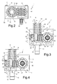
- the at least one elastically deformable tooth 24 is shaped so that, under substantially undeformed conditions, it interferes with the toothed wheel 19 so as to keep the same substantially in contact against the second abutting means, i.e. against the bottom wall 23 of seat 39, according to the configuration shown in figure 3 .
- the at least one elastically deformable tooth 24 is adapted to take an elastically deformed position in a stroke-end configuration of stem 12, shown in figure 4 , in which the toothed wheel 19 is in contact with the first abutting means, i.e. is abutting against the bottom wall 22 of seat 39.
- the elastic axial biasing means 24 consist of two teeth 24, each obtained in one piece for each half-shell 9,10, in a substantially tangential position with respect to the side walls of seats 32 and 39 and therebetween, according to a "fork-like" configuration, in plan view (not shown for simplicity), so that the end 14 of stem 12 may translate in use in the void therebetween, while these insist on face 30 of the toothed wheel 19.
- the extent G of the axial clearance for assembling the toothed wheel 19 between the first and second abutting means 22,23 is substantially equal to the length, measured in the axial direction, of the end length 26 of the first screw means 16.
- the first and second screw means consist of a threading 16 externally obtained on a side wall of stem 12, and a nut screw 20 obtained inside the toothed wheel 19, on a side wall of a through seat 40 thereof ( figure 2 ) for coupling with stem 12, respectively.
- the anti-rotation means consist of an axial flattening 18 obtained on the threading 16 of stem 12 which cooperates in use with a similar flattening (not shown for simplicity) inside the seat 32, otherwise cylindrical, as well as seat 39.
- control means 21 for the toothed wheel 19 consist of a worm screw 50 meshing with the toothed wheel 19, which is a helical-toothed wheel; the worm screw 50 is idly carried by the body 3 transversally to the stem 12 and by the side thereof and is provided with an axial control pin 52 projecting so as to protrude from the body 3 and provided with gripping means 54 for the mentioned stem-like tool, in this case consisting of a hexagonal prismatic head.
- the helical wheel 19 is rotated about axis A; this transmits motion to the stem 12 through the nut screw 20 which meshes with the threading 16; not being able to rotate about axis A due to the presence of the flattening 18, the stem 12 is thus forced to axially translate with respect to the body 3, sliding into the seat 32 and thus allowing the position of the floor resting means 13 to be adjusted in height.
- the toothed wheel 19 When the electric household appliance 2 needs to be moved, the toothed wheel 19 is rotated so as to "screw” the stem 12 into the nut screw 20 and therefore lift the electric household appliance 2. Conversely, for placing the electric household appliance 2 in a fixed position, the toothed wheel 19 is rotated so as to "unscrew” the stem 12 from the nut screw 20 and then lower the electric household appliance 2.
- the nut screw 20 is led into the threaded length 26 having the same height as the threads H progressively decreasing towards the end 14, until it is substantially reset.
- the axial reaction on the toothed wheel 19 moves the same towards the wall 22, abutting against the same, straining the teeth 2, which react with an axial bias S indicated by the arrow ( figure 4 ), which forces the lowered thread of the length 26 to be led into the nut screw again after a predetermined rotation of the nut screw 20 itself; therefore, the toothed wheel 19 "slips" with respect to the stem 12, alternatively moving between the positions in figure 3 and 4 , while the stem 12 remains axially static with respect to the body 3.
- Such a movement of the toothed wheel 19 requires from the user only the effort needed to elastically deform the tooth or teeth 24, which is absolutely modest.
- the tapping or clicking which is caused by the axial motion of the toothed wheel 19 further informs the user that the stroke-end position with foot 1 being lifted with respect to the casing 4 has been reached.
Landscapes
- Engineering & Computer Science (AREA)
- Textile Engineering (AREA)
- Transmission Devices (AREA)
- Finger-Pressure Massage (AREA)
- Devices For Medical Bathing And Washing (AREA)
- Thermotherapy And Cooling Therapy Devices (AREA)
Description
- The present invention relates to an adjustable foot, in particular a rear foot, for an electric household appliance. Such a type of foot is usually used in electric household appliances, especially of the fitted type, such as washing machines and/or dishwashers, for both levelling the electric household appliance and possibly moving it, e.g. for maintenance interventions or cleaning.
- An adjustable foot is known from
EP-A-1895040 , for example, in which a stem provided with floor resting means and an external threading meshes with a nut screw obtained inside a toothed wheel, which is rotationally actuated by a worm screw which is controllable by the user. Such a type of height-adjustment device for the foot has the problem of managing the stroke-end, when the foot is raised; indeed, the foot is usually arranged behind the electric household appliance but is controlled from the front, e.g. by means of a tool inserted through a hole of the front panel, whereby it may not be seen. Sticking or damages to the thread may occur if the user applies a torque on the worm screw at the stroke-end, without considering the excessive effort required by the user when manoeuvring. In order to allow the thread to slip to a stroke-end position, a nut screw consisting of two or more half-elements held together by a spring has been suggested. However, such a solution is complex, cumbersome and requires the user to apply a high torque for controlling the worm screw. - It is an object of the present invention to solve the aforesaid problem by providing a height-adjustable foot for an electric household appliance which has a simple, cost-effective construction, is small in size, very reliable, and which allows to obtain a slipping at the stroke-end when lifting the foot, which avoids the thread from being forced by applying extra-torque on the worm screw by the user, which is minimum and in all cases much less than that needed in the known solutions.
- The present invention thus relates to an adjustable foot for an electric household appliance, as defined in
claim 1. - In particular, the foot according to the invention comprises a body integrally fastenable to a casing of the electric household appliance, a stem carried by the body so as to vertically slide, floor resting means associated with a lower end of the stem, first screw means operatively associated with the stem and provided with anti-rotation means cooperating with the body, a toothed wheel carried by the body so as to be coaxial to the stem and idle about a substantially vertical symmetry axis of the latter, second screw means operatively associated with the toothed wheel and cooperating with the first screw means for vertically translating the stem in response to a rotation of the toothed wheel, and control means for the toothed wheel.
- According to an aspect of the invention, the toothed wheel is axially mounted with a clearance between opposite first and second abutting means of the body, which is provided with elastic axial biasing means cooperating with the toothed wheel and arranged at the first abutting means; the latter face towards an end length of the first screw means having a thread height gradually decreasing towards the elastic axial biasing means.
- The extent of the axial clearance for assembling the toothed wheel between the first and second abutting means is substantially equal to the length, measured in the axial direction, of the end length of the first screw means.
- The elastic axial biasing means preferably consist of at least one elastically deformable tooth integrally formed in one piece with the body, which is made of synthetic plastic material, which tooth transversally extends so as to protrude with respect to the symmetry axis of the stem, within respective seats for accommodating the stem and the toothed wheel, obtained inside the body; the at least one elastically deformable tooth is shaped so that, under undeformed conditions, it interferes with the toothed wheel so as to keep the same in contact against the second abutting means.
- Thereby, when the stroke-end position is reached, i.e. when the second screw means associated with the toothed wheel mesh with the end length of the first screw means, associated with the stem, the toothed wheel which is normally held by the elastic axial biasing means against the second abutting means, is pushed by the "unscrewing" action of the end length of the first screw means against the first abutting means, thus straining the elastic axial biasing means, which react with an axial stress which pushes the toothed wheel back towards the second abutting means; the thread height of the end length of the first screw means being progressively decreasing towards the first abutting means and the elastic axial biasing means associated therewith, if the user continues actuating the toothed wheel, it "slips" on the stem with minimum increase of torque to be exerted by the user, because it corresponds to the elastic deformation force of the elastic axial biasing means only, which is also minimum because the axial elastic stress which they should exert on the toothed wheel is the only one which allows the screw means associated with the toothed wheel to return to mesh the lowered thread of the end length of the screw means associated with the stem as soon as "unscrewing" is completed, with consequent ceasing of the axial bias on the toothed wheel by the stem.
- Further features and advantages of the present invention will become apparent from the following description of a preferred embodiment thereof, merely provided by way of non-limitative example, with reference to the accompanying drawings, in which:
-
figure 1 diagrammatically shows an elevation view of an adjustable foot for an electric household appliance provided according to the invention; -
figure 2 is a top plan view of the adjustable foot infigure 1 ; and -
figures 3 and 4 shows side elevation views of the adjustable foot infigure 1 with parts removed, in two different operating stroke-end configurations. - With reference to figures from 1 to 4,
numeral 1 indicates as a whole an adjustable foot for anelectric household appliance 2, in particular a rear foot for a fitted washing machine or dishwasher. -
Foot 1 comprises abody 3 integrally fastenable to acasing 4 of the electric household appliance, which has afront panel 5 provided with ahole 6 for actuating thefoot 1 by means of an appropriate stem-like tool, of known type and not shown for simplicity, whilefoot 1 is arranged at arear panel 7. In particular,body 3 is made by coupling two half-shells screws 11 and is made by moulding a synthetic plastic material. -
Foot 1 further comprises astem 12 vertically carried by thebody 3, restingmeans 13 on afloor 13b associated with a lower end 14 (figures 3,4 ) of thestem 12 and possibly provided with awheel 15, first screw means 16 operatively associated with thestem 12 and provided with anti-rotation means 18 cooperating with the body, atoothed wheel 19 carried by thebody 3 so as to be coaxial to thestem 12 and idle about a substantially vertical symmetry axis A of thestem 12 itself, second screw means 20 operatively associated with thetoothed wheel 19 and cooperating with the first screw means 16 to vertically translate thestem 12 with respect to thebody 3 in response to a rotation of thetoothed wheel 19, and control means 21 for thetoothed wheel 19. - According to an aspect of the invention, the
toothed wheel 19 is axially mounted with a clearance, of extent G, between opposite first and second abutting means of thebody 3, indicated by 22 and 23, respectively. In combination,body 3 is provided with elastic axial biasing means 24 cooperating with thetoothed wheel 19 and arranged at the first abutting means 22; furthermore, the latter face towards anend length 26 of the screw means 16 having a thread height H (figure 3 ) gradually decreasing towards the elastic axial biasing means 24, i.e. towards thelower end 14 ofstem 12, which is free from the screw means 16. - The abutting means 23 are facing towards the floor resting
means 13 and, similarly, also towards the elastic axial biasing means 24; the latter are arranged on the side opposite to theend length 26 of the first screw means 16 with respect to thelower end 14 ofstem 12. - According to a preferred aspect of the invention, the elastic axial biasing means 24 directly cooperate in contact with a lower
frontal face 30 of the toothed wheel 19 (figure 3 ) and consist of at least one elasticallydeformable tooth 24 integrally formed in one piece with thebody 3 and transversally extending so as to protrude with respect to axis A withinrespective seats 32 and 39 (figure 3 ) for accommodating thestem 12 and thetoothed wheel 19, obtained inside thebody 3, in particular half in half-shell 9 and half in half-shell 10. - The first and second abutting means consist of respective annular
bottom end walls seat 39 for accommodating thetoothed wheel 19; in particular, theseat 39 is radially obtained outside and at theseat 32 for accommodating thestem 12. - Furthermore, the at least one elastically
deformable tooth 24 is shaped so that, under substantially undeformed conditions, it interferes with thetoothed wheel 19 so as to keep the same substantially in contact against the second abutting means, i.e. against thebottom wall 23 ofseat 39, according to the configuration shown infigure 3 . - Furthermore, the at least one elastically
deformable tooth 24 is adapted to take an elastically deformed position in a stroke-end configuration ofstem 12, shown infigure 4 , in which thetoothed wheel 19 is in contact with the first abutting means, i.e. is abutting against thebottom wall 22 ofseat 39. - Preferably, the elastic axial biasing means 24 consist of two
teeth 24, each obtained in one piece for each half-shell seats end 14 ofstem 12 may translate in use in the void therebetween, while these insist onface 30 of thetoothed wheel 19. - The extent G of the axial clearance for assembling the
toothed wheel 19 between the first and second abutting means 22,23 is substantially equal to the length, measured in the axial direction, of theend length 26 of the first screw means 16. - In this illustrated case, the first and second screw means consist of a
threading 16 externally obtained on a side wall ofstem 12, and anut screw 20 obtained inside thetoothed wheel 19, on a side wall of a throughseat 40 thereof (figure 2 ) for coupling withstem 12, respectively. - Furthermore, the anti-rotation means consist of an
axial flattening 18 obtained on thethreading 16 ofstem 12 which cooperates in use with a similar flattening (not shown for simplicity) inside theseat 32, otherwise cylindrical, as well asseat 39. - Finally, in the illustrated example, the control means 21 for the
toothed wheel 19 consist of aworm screw 50 meshing with thetoothed wheel 19, which is a helical-toothed wheel; theworm screw 50 is idly carried by thebody 3 transversally to thestem 12 and by the side thereof and is provided with anaxial control pin 52 projecting so as to protrude from thebody 3 and provided with gripping means 54 for the mentioned stem-like tool, in this case consisting of a hexagonal prismatic head. - In use, by rotating the
pin 52 by means of the aforesaid stem-like tool, introduced through thehole 6 intocasing 4, thehelical wheel 19 is rotated about axis A; this transmits motion to thestem 12 through thenut screw 20 which meshes with thethreading 16; not being able to rotate about axis A due to the presence of the flattening 18, thestem 12 is thus forced to axially translate with respect to thebody 3, sliding into theseat 32 and thus allowing the position of the floor resting means 13 to be adjusted in height. - When the
electric household appliance 2 needs to be moved, thetoothed wheel 19 is rotated so as to "screw" thestem 12 into thenut screw 20 and therefore lift theelectric household appliance 2. Conversely, for placing theelectric household appliance 2 in a fixed position, thetoothed wheel 19 is rotated so as to "unscrew" thestem 12 from thenut screw 20 and then lower theelectric household appliance 2. - Once the stroke-end position has been reached (maximum lifting of
foot 1 with respect to the casing 2), thenut screw 20 is led into the threadedlength 26 having the same height as the threads H progressively decreasing towards theend 14, until it is substantially reset. When the thread of thelength 26 is completely unscrewed from thenut screw 20, the axial reaction on thetoothed wheel 19 moves the same towards thewall 22, abutting against the same, straining theteeth 2, which react with an axial bias S indicated by the arrow (figure 4 ), which forces the lowered thread of thelength 26 to be led into the nut screw again after a predetermined rotation of thenut screw 20 itself; therefore, thetoothed wheel 19 "slips" with respect to thestem 12, alternatively moving between the positions infigure 3 and 4 , while thestem 12 remains axially static with respect to thebody 3. Such a movement of thetoothed wheel 19 requires from the user only the effort needed to elastically deform the tooth orteeth 24, which is absolutely modest. - The tapping or clicking which is caused by the axial motion of the
toothed wheel 19 further informs the user that the stroke-end position withfoot 1 being lifted with respect to thecasing 4 has been reached.
Claims (10)
- An adjustable foot (1) for an electric household appliance (2), in particular a rear foot for a washing machine, comprising a body (3) integrally fastenable to a casing (4) of the electric household appliance, a stem (12) carried by the body so as to vertically slide, floor resting means (13) associated with a lower end (14) of the stem, first screw means (16) operatively associated with the stem and provided with anti-rotation means (18) cooperating with the body (3), a toothed wheel (19) carried by the body so as to be coaxial to the stem (12) and idle about a substantially vertical symmetry axis (A) of the latter, second screw means (20) operatively associated with the toothed wheel (19) and cooperating with the first screw means (16) for vertically translating the stem (12) in response to a rotation of the toothed wheel (19), and control means (21) for the toothed wheel; characterized in that the toothed wheel (19) is axially mounted with a clearance (G) between opposite first (22) and second (23) abutting means of the body, which is provided with elastic axial biasing means (24) cooperating with the toothed wheel (19) and arranged at the first abutting means (22), the latter facing towards an end length (26) of the first screw means (16) having a thread height (H) gradually decreasing towards the elastic axial biasing means (24).
- An adjustable foot according to claim 1, characterized in that said second abutting means (23) are facing towards said floor resting means (13) and towards said elastic axial biasing means (24), which are arranged on the side opposite to the end length (26) of the first screw means (16) with respect to said lower end (14) of the stem (12).
- An adjustable foot according to claim 1 or 2, characterized in that said elastic axial biasing means (24) directly cooperate in contact with a lower frontal face (30) of the toothed wheel (19).
- An adjustable foot according to one of the preceding claims, characterized in that said elastic axial biasing means consist of at least one elastically deformable tooth (24) integrally formed in one piece with said body (3) and transversally extending so as to protrude with respect to the symmetry axis (A) of the stem, within respective seats (32,39) for accommodating the stem (12) and the toothed wheel (19), obtained inside the body (3).
- An adjustable foot according to claim 4, characterized in that said first and second abutting means consist of respective annular bottom end walls (22,23) of the seat (39) for accommodating the toothed wheel (19), which seat (39) is radially obtained outside and at said seat (32) for accommodating the stem (12); said at least one elastically deformable tooth (24) being shaped so that, under undeformed conditions, it interferes with the toothed wheel (19) so as to bias the same substantially in contact against the second abutting means (23).
- An adjustable foot according to claim 5, characterized in that said at least one elastically deformable tooth (24) is adapted to take an elastically deformed position in which said toothed wheel (19) is in contact against the first abutting means (22).
- An adjustable foot according to one of the preceding claims, characterized in that the amount of said axial clearance (G) for mounting the toothed wheel (19) between the first and second abutting means (22,23) is substantially equal to the length, measured in the axial direction, of said end length (26) of the first screw means (16).
- An adjustable foot according to one of the preceding claims, characterized in that said first and second screw means consist of a threading (16) externally obtained on a side wall of the stem (12), and a nut screw (20) obtained inside the toothed wheel (19), on a side wall of a through seat (40) thereof coupling with the stem (12), respectively.
- An adjustable foot according to claim 8, characterised in that said anti-rotation means consist of an axial flattening (18) obtained on said threading (16) of the stem (12).
- An adjustable foot according to one of the preceding claims, characterized in that said control means (21) for the toothed wheel consist of a worm screw (50) meshing with the toothed wheel (19), which is a helical-toothing wheel; the worm screw (50) being idly carried by the body (3) transversally to the stem (12) and by the side thereof; said worm screw (50) being provided with an axial control pin projecting so as to protrude from the body (3) and provided with gripping means (54).
Priority Applications (1)
| Application Number | Priority Date | Filing Date | Title |
|---|---|---|---|
| PL10704710T PL2398953T3 (en) | 2009-02-17 | 2010-02-16 | Adjustable foot, in particular a rear foot, for an electric household appliance |
Applications Claiming Priority (2)
| Application Number | Priority Date | Filing Date | Title |
|---|---|---|---|
| ITTO2009A000114A IT1392975B1 (en) | 2009-02-17 | 2009-02-17 | ADJUSTABLE FEET, IN PARTICULAR A REAR FOOT, FOR A HOUSEHOLD APPLIANCE |
| PCT/US2010/024249 WO2010096364A1 (en) | 2009-02-17 | 2010-02-16 | Adjustable foot, in particular a rear foot, for an electric household appliance |
Publications (2)
| Publication Number | Publication Date |
|---|---|
| EP2398953A1 EP2398953A1 (en) | 2011-12-28 |
| EP2398953B1 true EP2398953B1 (en) | 2015-04-15 |
Family
ID=41112646
Family Applications (1)
| Application Number | Title | Priority Date | Filing Date |
|---|---|---|---|
| EP10704710.2A Active EP2398953B1 (en) | 2009-02-17 | 2010-02-16 | Adjustable foot, in particular a rear foot, for an electric household appliance |
Country Status (5)
| Country | Link |
|---|---|
| US (1) | US8695933B2 (en) |
| EP (1) | EP2398953B1 (en) |
| IT (1) | IT1392975B1 (en) |
| PL (1) | PL2398953T3 (en) |
| WO (1) | WO2010096364A1 (en) |
Cited By (1)
| Publication number | Priority date | Publication date | Assignee | Title |
|---|---|---|---|---|
| CN104983381A (en) * | 2015-07-13 | 2015-10-21 | 佛山市顺德区美的洗涤电器制造有限公司 | Domestic electric appliance and adjustment device for domestic electric appliance |
Families Citing this family (13)
| Publication number | Priority date | Publication date | Assignee | Title |
|---|---|---|---|---|
| DE102010063919A1 (en) * | 2010-12-22 | 2012-06-28 | BSH Bosch und Siemens Hausgeräte GmbH | Household appliance, especially stove |
| TR201103077A2 (en) * | 2011-03-31 | 2012-10-22 | Bsh Ev Aletler� San. Ve T�C. A.�. | A built-in household appliance. |
| US9572429B2 (en) * | 2013-05-03 | 2017-02-21 | Arcelik Anonim Sirketi | Household appliance having improved height profile adjustable feet |
| KR20160067968A (en) | 2013-10-11 | 2016-06-14 | 디자이너스코프 리미티드 | Cabinet levelling apparatus |
| US10006582B2 (en) * | 2014-11-03 | 2018-06-26 | Arcelik Anonim Sirketi | Household appliance with control height adjustment mechanism |
| KR102376043B1 (en) * | 2015-07-14 | 2022-03-18 | 엘지전자 주식회사 | Dishwasher |
| CN109415862B (en) * | 2016-06-30 | 2022-03-01 | 伊莱克斯电器股份公司 | Dish washing machine |
| US10376129B2 (en) * | 2016-11-08 | 2019-08-13 | Whirlpool Corporation | Dishwasher leveling assembly |
| US9803730B1 (en) * | 2016-11-21 | 2017-10-31 | Bsh Hausgeraete Gmbh | Home appliance device |
| WO2019043660A1 (en) | 2017-09-04 | 2019-03-07 | Designerscope Limited | Cabinet levelling apparatus |
| CN110836303B (en) * | 2018-08-17 | 2023-01-03 | 青岛海尔多媒体有限公司 | Footing structure and household appliance with same |
| CN109898260B (en) * | 2019-04-24 | 2021-03-26 | 董泽皓 | Pedal washing machine |
| CN113865226B (en) * | 2020-06-30 | 2022-12-20 | 青岛海尔电冰箱有限公司 | Mounting feet and refrigerators having them |
Family Cites Families (6)
| Publication number | Priority date | Publication date | Assignee | Title |
|---|---|---|---|---|
| US4991805A (en) * | 1989-05-17 | 1991-02-12 | Whirlpool Corporation | Refrigerator gear driven leveling system |
| IT1249605B (en) * | 1991-02-26 | 1995-03-09 | Camar Spa | LEVELER DEVICE IN PARTICULAR FOR FURNITURE |
| US6729590B2 (en) | 2002-01-23 | 2004-05-04 | Edward Gabriel | Leveling device |
| DE202004017329U1 (en) * | 2004-11-09 | 2006-03-16 | Liebherr-Hausgeräte Lienz Gmbh | Height adjustable foot for household appliance especially cooler or refrigerator has threaded shaft worm gear drive shaft and force fit of shaft to housing |
| EP1895040B1 (en) * | 2006-08-29 | 2008-11-05 | Bonferraro S.p.A. | System for adjusting the height of a built-in household appliance, in particular a washing machine |
| DE102007057511B3 (en) * | 2007-11-29 | 2009-07-16 | BSH Bosch und Siemens Hausgeräte GmbH | Household appliance with a height adjustment device for a device foot |
-
2009
- 2009-02-17 IT ITTO2009A000114A patent/IT1392975B1/en active
-
2010
- 2010-02-16 EP EP10704710.2A patent/EP2398953B1/en active Active
- 2010-02-16 WO PCT/US2010/024249 patent/WO2010096364A1/en not_active Ceased
- 2010-02-16 US US13/201,682 patent/US8695933B2/en active Active
- 2010-02-16 PL PL10704710T patent/PL2398953T3/en unknown
Cited By (1)
| Publication number | Priority date | Publication date | Assignee | Title |
|---|---|---|---|---|
| CN104983381A (en) * | 2015-07-13 | 2015-10-21 | 佛山市顺德区美的洗涤电器制造有限公司 | Domestic electric appliance and adjustment device for domestic electric appliance |
Also Published As
| Publication number | Publication date |
|---|---|
| US20110297802A1 (en) | 2011-12-08 |
| ITTO20090114A1 (en) | 2010-08-18 |
| US8695933B2 (en) | 2014-04-15 |
| EP2398953A1 (en) | 2011-12-28 |
| IT1392975B1 (en) | 2012-04-02 |
| PL2398953T3 (en) | 2015-08-31 |
| WO2010096364A1 (en) | 2010-08-26 |
Similar Documents
| Publication | Publication Date | Title |
|---|---|---|
| US8695933B2 (en) | Adjustable foot, in particular a rear foot, for an electric household appliance | |
| EP2335539B1 (en) | Apparatus for hands-free dispensing of a measured quantity of material | |
| EP2884875B1 (en) | Electrically operated kitchen appliance | |
| EP2519680B1 (en) | A household appliance | |
| WO2016050121A1 (en) | Rivet nut electric tool | |
| DE502008003211D1 (en) | HOUSEHOLD UNIT WITH A HEIGHT ADJUSTMENT DEVICE FOR A DEVICE FOOT | |
| CN107595225B (en) | Opening and closing structure of box door cover of water tank dish washer | |
| CN105496170A (en) | automatic juicer | |
| KR20170121510A (en) | Faucet assembly | |
| CN106869262B (en) | Remote operation type drainage plug device | |
| EP2103749A2 (en) | Spout, particularly for washbasins and the like, with device for automatic activation of a valve body | |
| CN216788052U (en) | Door lock mechanism for household appliance and household appliance | |
| CN108547127B (en) | Gear limit adjusting device of clothes hanger | |
| CN212641647U (en) | a button device | |
| JP6682080B2 (en) | Remote operated drain plug device | |
| CN203815212U (en) | Safe cooking device | |
| US20210378403A1 (en) | Domestic appliance | |
| CN204690877U (en) | A kind of line-controlled draining-valve control device | |
| CN101543391A (en) | Adjustable support foot of dishwasher | |
| CN201303926Y (en) | Height adjusting mechanism of embedded dish washer | |
| CN106400906B (en) | A kind of two-way knob platform control | |
| CN106206094A (en) | A kind of Revolving-drum static contact isolation switch cleans device | |
| CN201962517U (en) | Control device for opening and closing valve | |
| CA2797522A1 (en) | Remote controller unit for control of a valve of a drain fitting | |
| DE102011010615A1 (en) | Household appliance e.g. cooling and/or freezing apparatus, has comparison unit comparing operation duration of appliance with upper- and lower threshold values, so that function is activated when duration lies between threshold values |
Legal Events
| Date | Code | Title | Description |
|---|---|---|---|
| PUAI | Public reference made under article 153(3) epc to a published international application that has entered the european phase |
Free format text: ORIGINAL CODE: 0009012 |
|
| 17P | Request for examination filed |
Effective date: 20110917 |
|
| AK | Designated contracting states |
Kind code of ref document: A1 Designated state(s): AT BE BG CH CY CZ DE DK EE ES FI FR GB GR HR HU IE IS IT LI LT LU LV MC MK MT NL NO PL PT RO SE SI SK SM TR |
|
| DAX | Request for extension of the european patent (deleted) | ||
| RAP1 | Party data changed (applicant data changed or rights of an application transferred) |
Owner name: ILLINOIS TOOL WORKS INC. |
|
| GRAP | Despatch of communication of intention to grant a patent |
Free format text: ORIGINAL CODE: EPIDOSNIGR1 |
|
| INTG | Intention to grant announced |
Effective date: 20141121 |
|
| RIN1 | Information on inventor provided before grant (corrected) |
Inventor name: CARLI, PIERLUIGI Inventor name: GENNARETTI, LUCA |
|
| GRAS | Grant fee paid |
Free format text: ORIGINAL CODE: EPIDOSNIGR3 |
|
| GRAA | (expected) grant |
Free format text: ORIGINAL CODE: 0009210 |
|
| AK | Designated contracting states |
Kind code of ref document: B1 Designated state(s): AT BE BG CH CY CZ DE DK EE ES FI FR GB GR HR HU IE IS IT LI LT LU LV MC MK MT NL NO PL PT RO SE SI SK SM TR |
|
| REG | Reference to a national code |
Ref country code: GB Ref legal event code: FG4D Ref country code: CH Ref legal event code: EP |
|
| REG | Reference to a national code |
Ref country code: IE Ref legal event code: FG4D |
|
| REG | Reference to a national code |
Ref country code: AT Ref legal event code: REF Ref document number: 722054 Country of ref document: AT Kind code of ref document: T Effective date: 20150515 |
|
| REG | Reference to a national code |
Ref country code: DE Ref legal event code: R096 Ref document number: 602010023945 Country of ref document: DE Effective date: 20150528 |
|
| REG | Reference to a national code |
Ref country code: PL Ref legal event code: T3 |
|
| REG | Reference to a national code |
Ref country code: NL Ref legal event code: VDEP Effective date: 20150415 |
|
| REG | Reference to a national code |
Ref country code: AT Ref legal event code: MK05 Ref document number: 722054 Country of ref document: AT Kind code of ref document: T Effective date: 20150415 |
|
| REG | Reference to a national code |
Ref country code: LT Ref legal event code: MG4D |
|
| PG25 | Lapsed in a contracting state [announced via postgrant information from national office to epo] |
Ref country code: NL Free format text: LAPSE BECAUSE OF FAILURE TO SUBMIT A TRANSLATION OF THE DESCRIPTION OR TO PAY THE FEE WITHIN THE PRESCRIBED TIME-LIMIT Effective date: 20150415 |
|
| PG25 | Lapsed in a contracting state [announced via postgrant information from national office to epo] |
Ref country code: NO Free format text: LAPSE BECAUSE OF FAILURE TO SUBMIT A TRANSLATION OF THE DESCRIPTION OR TO PAY THE FEE WITHIN THE PRESCRIBED TIME-LIMIT Effective date: 20150715 Ref country code: HR Free format text: LAPSE BECAUSE OF FAILURE TO SUBMIT A TRANSLATION OF THE DESCRIPTION OR TO PAY THE FEE WITHIN THE PRESCRIBED TIME-LIMIT Effective date: 20150415 Ref country code: FI Free format text: LAPSE BECAUSE OF FAILURE TO SUBMIT A TRANSLATION OF THE DESCRIPTION OR TO PAY THE FEE WITHIN THE PRESCRIBED TIME-LIMIT Effective date: 20150415 Ref country code: LT Free format text: LAPSE BECAUSE OF FAILURE TO SUBMIT A TRANSLATION OF THE DESCRIPTION OR TO PAY THE FEE WITHIN THE PRESCRIBED TIME-LIMIT Effective date: 20150415 Ref country code: PT Free format text: LAPSE BECAUSE OF FAILURE TO SUBMIT A TRANSLATION OF THE DESCRIPTION OR TO PAY THE FEE WITHIN THE PRESCRIBED TIME-LIMIT Effective date: 20150817 Ref country code: ES Free format text: LAPSE BECAUSE OF FAILURE TO SUBMIT A TRANSLATION OF THE DESCRIPTION OR TO PAY THE FEE WITHIN THE PRESCRIBED TIME-LIMIT Effective date: 20150415 |
|
| PG25 | Lapsed in a contracting state [announced via postgrant information from national office to epo] |
Ref country code: AT Free format text: LAPSE BECAUSE OF FAILURE TO SUBMIT A TRANSLATION OF THE DESCRIPTION OR TO PAY THE FEE WITHIN THE PRESCRIBED TIME-LIMIT Effective date: 20150415 Ref country code: LV Free format text: LAPSE BECAUSE OF FAILURE TO SUBMIT A TRANSLATION OF THE DESCRIPTION OR TO PAY THE FEE WITHIN THE PRESCRIBED TIME-LIMIT Effective date: 20150415 Ref country code: IS Free format text: LAPSE BECAUSE OF FAILURE TO SUBMIT A TRANSLATION OF THE DESCRIPTION OR TO PAY THE FEE WITHIN THE PRESCRIBED TIME-LIMIT Effective date: 20150815 Ref country code: GR Free format text: LAPSE BECAUSE OF FAILURE TO SUBMIT A TRANSLATION OF THE DESCRIPTION OR TO PAY THE FEE WITHIN THE PRESCRIBED TIME-LIMIT Effective date: 20150716 |
|
| REG | Reference to a national code |
Ref country code: DE Ref legal event code: R097 Ref document number: 602010023945 Country of ref document: DE |
|
| PG25 | Lapsed in a contracting state [announced via postgrant information from national office to epo] |
Ref country code: EE Free format text: LAPSE BECAUSE OF FAILURE TO SUBMIT A TRANSLATION OF THE DESCRIPTION OR TO PAY THE FEE WITHIN THE PRESCRIBED TIME-LIMIT Effective date: 20150415 Ref country code: DK Free format text: LAPSE BECAUSE OF FAILURE TO SUBMIT A TRANSLATION OF THE DESCRIPTION OR TO PAY THE FEE WITHIN THE PRESCRIBED TIME-LIMIT Effective date: 20150415 |
|
| PLBE | No opposition filed within time limit |
Free format text: ORIGINAL CODE: 0009261 |
|
| STAA | Information on the status of an ep patent application or granted ep patent |
Free format text: STATUS: NO OPPOSITION FILED WITHIN TIME LIMIT |
|
| PG25 | Lapsed in a contracting state [announced via postgrant information from national office to epo] |
Ref country code: SK Free format text: LAPSE BECAUSE OF FAILURE TO SUBMIT A TRANSLATION OF THE DESCRIPTION OR TO PAY THE FEE WITHIN THE PRESCRIBED TIME-LIMIT Effective date: 20150415 Ref country code: RO Free format text: LAPSE BECAUSE OF NON-PAYMENT OF DUE FEES Effective date: 20150415 Ref country code: CZ Free format text: LAPSE BECAUSE OF FAILURE TO SUBMIT A TRANSLATION OF THE DESCRIPTION OR TO PAY THE FEE WITHIN THE PRESCRIBED TIME-LIMIT Effective date: 20150415 |
|
| 26N | No opposition filed |
Effective date: 20160118 |
|
| PG25 | Lapsed in a contracting state [announced via postgrant information from national office to epo] |
Ref country code: SI Free format text: LAPSE BECAUSE OF FAILURE TO SUBMIT A TRANSLATION OF THE DESCRIPTION OR TO PAY THE FEE WITHIN THE PRESCRIBED TIME-LIMIT Effective date: 20150415 Ref country code: BE Free format text: LAPSE BECAUSE OF NON-PAYMENT OF DUE FEES Effective date: 20160229 |
|
| PG25 | Lapsed in a contracting state [announced via postgrant information from national office to epo] |
Ref country code: BE Free format text: LAPSE BECAUSE OF FAILURE TO SUBMIT A TRANSLATION OF THE DESCRIPTION OR TO PAY THE FEE WITHIN THE PRESCRIBED TIME-LIMIT Effective date: 20150415 |
|
| PG25 | Lapsed in a contracting state [announced via postgrant information from national office to epo] |
Ref country code: LU Free format text: LAPSE BECAUSE OF FAILURE TO SUBMIT A TRANSLATION OF THE DESCRIPTION OR TO PAY THE FEE WITHIN THE PRESCRIBED TIME-LIMIT Effective date: 20160216 Ref country code: MC Free format text: LAPSE BECAUSE OF FAILURE TO SUBMIT A TRANSLATION OF THE DESCRIPTION OR TO PAY THE FEE WITHIN THE PRESCRIBED TIME-LIMIT Effective date: 20150415 |
|
| REG | Reference to a national code |
Ref country code: CH Ref legal event code: PL |
|
| GBPC | Gb: european patent ceased through non-payment of renewal fee |
Effective date: 20160216 |
|
| PG25 | Lapsed in a contracting state [announced via postgrant information from national office to epo] |
Ref country code: CH Free format text: LAPSE BECAUSE OF NON-PAYMENT OF DUE FEES Effective date: 20160229 Ref country code: LI Free format text: LAPSE BECAUSE OF NON-PAYMENT OF DUE FEES Effective date: 20160229 |
|
| REG | Reference to a national code |
Ref country code: FR Ref legal event code: ST Effective date: 20161028 |
|
| REG | Reference to a national code |
Ref country code: IE Ref legal event code: MM4A |
|
| PG25 | Lapsed in a contracting state [announced via postgrant information from national office to epo] |
Ref country code: GB Free format text: LAPSE BECAUSE OF NON-PAYMENT OF DUE FEES Effective date: 20160216 Ref country code: IE Free format text: LAPSE BECAUSE OF NON-PAYMENT OF DUE FEES Effective date: 20160216 Ref country code: FR Free format text: LAPSE BECAUSE OF NON-PAYMENT OF DUE FEES Effective date: 20160229 |
|
| PG25 | Lapsed in a contracting state [announced via postgrant information from national office to epo] |
Ref country code: SE Free format text: LAPSE BECAUSE OF FAILURE TO SUBMIT A TRANSLATION OF THE DESCRIPTION OR TO PAY THE FEE WITHIN THE PRESCRIBED TIME-LIMIT Effective date: 20150415 |
|
| PG25 | Lapsed in a contracting state [announced via postgrant information from national office to epo] |
Ref country code: MT Free format text: LAPSE BECAUSE OF FAILURE TO SUBMIT A TRANSLATION OF THE DESCRIPTION OR TO PAY THE FEE WITHIN THE PRESCRIBED TIME-LIMIT Effective date: 20150415 |
|
| PG25 | Lapsed in a contracting state [announced via postgrant information from national office to epo] |
Ref country code: HU Free format text: LAPSE BECAUSE OF FAILURE TO SUBMIT A TRANSLATION OF THE DESCRIPTION OR TO PAY THE FEE WITHIN THE PRESCRIBED TIME-LIMIT; INVALID AB INITIO Effective date: 20100216 Ref country code: SM Free format text: LAPSE BECAUSE OF FAILURE TO SUBMIT A TRANSLATION OF THE DESCRIPTION OR TO PAY THE FEE WITHIN THE PRESCRIBED TIME-LIMIT Effective date: 20150415 Ref country code: CY Free format text: LAPSE BECAUSE OF FAILURE TO SUBMIT A TRANSLATION OF THE DESCRIPTION OR TO PAY THE FEE WITHIN THE PRESCRIBED TIME-LIMIT Effective date: 20150415 |
|
| PG25 | Lapsed in a contracting state [announced via postgrant information from national office to epo] |
Ref country code: MK Free format text: LAPSE BECAUSE OF FAILURE TO SUBMIT A TRANSLATION OF THE DESCRIPTION OR TO PAY THE FEE WITHIN THE PRESCRIBED TIME-LIMIT Effective date: 20150415 Ref country code: MT Free format text: LAPSE BECAUSE OF FAILURE TO SUBMIT A TRANSLATION OF THE DESCRIPTION OR TO PAY THE FEE WITHIN THE PRESCRIBED TIME-LIMIT Effective date: 20160229 |
|
| PG25 | Lapsed in a contracting state [announced via postgrant information from national office to epo] |
Ref country code: BG Free format text: LAPSE BECAUSE OF FAILURE TO SUBMIT A TRANSLATION OF THE DESCRIPTION OR TO PAY THE FEE WITHIN THE PRESCRIBED TIME-LIMIT Effective date: 20150415 |
|
| PGFP | Annual fee paid to national office [announced via postgrant information from national office to epo] |
Ref country code: IT Payment date: 20230221 Year of fee payment: 14 Ref country code: DE Payment date: 20230223 Year of fee payment: 14 |
|
| P01 | Opt-out of the competence of the unified patent court (upc) registered |
Effective date: 20230606 |
|
| PGFP | Annual fee paid to national office [announced via postgrant information from national office to epo] |
Ref country code: TR Payment date: 20240202 Year of fee payment: 15 Ref country code: PL Payment date: 20240201 Year of fee payment: 15 |
|
| REG | Reference to a national code |
Ref country code: DE Ref legal event code: R119 Ref document number: 602010023945 Country of ref document: DE |
|
| PG25 | Lapsed in a contracting state [announced via postgrant information from national office to epo] |
Ref country code: DE Free format text: LAPSE BECAUSE OF NON-PAYMENT OF DUE FEES Effective date: 20240903 |
|
| PG25 | Lapsed in a contracting state [announced via postgrant information from national office to epo] |
Ref country code: DE Free format text: LAPSE BECAUSE OF NON-PAYMENT OF DUE FEES Effective date: 20240903 |
|
| PG25 | Lapsed in a contracting state [announced via postgrant information from national office to epo] |
Ref country code: IT Free format text: LAPSE BECAUSE OF NON-PAYMENT OF DUE FEES Effective date: 20240216 |