EP2398623B1 - Fixture for securing a thin-walled component, comprising a liner with one or more elastic members and slits - Google Patents
Fixture for securing a thin-walled component, comprising a liner with one or more elastic members and slits Download PDFInfo
- Publication number
- EP2398623B1 EP2398623B1 EP10702049A EP10702049A EP2398623B1 EP 2398623 B1 EP2398623 B1 EP 2398623B1 EP 10702049 A EP10702049 A EP 10702049A EP 10702049 A EP10702049 A EP 10702049A EP 2398623 B1 EP2398623 B1 EP 2398623B1
- Authority
- EP
- European Patent Office
- Prior art keywords
- liner
- pressure element
- fixture
- component
- securing
- Prior art date
- Legal status (The legal status is an assumption and is not a legal conclusion. Google has not performed a legal analysis and makes no representation as to the accuracy of the status listed.)
- Active
Links
Images


Classifications
-
- B—PERFORMING OPERATIONS; TRANSPORTING
- B23—MACHINE TOOLS; METAL-WORKING NOT OTHERWISE PROVIDED FOR
- B23Q—DETAILS, COMPONENTS, OR ACCESSORIES FOR MACHINE TOOLS, e.g. ARRANGEMENTS FOR COPYING OR CONTROLLING; MACHINE TOOLS IN GENERAL CHARACTERISED BY THE CONSTRUCTION OF PARTICULAR DETAILS OR COMPONENTS; COMBINATIONS OR ASSOCIATIONS OF METAL-WORKING MACHINES, NOT DIRECTED TO A PARTICULAR RESULT
- B23Q3/00—Devices holding, supporting, or positioning work or tools, of a kind normally removable from the machine
- B23Q3/02—Devices holding, supporting, or positioning work or tools, of a kind normally removable from the machine for mounting on a work-table, tool-slide, or analogous part
- B23Q3/06—Work-clamping means
- B23Q3/062—Work-clamping means adapted for holding workpieces having a special form or being made from a special material
-
- B—PERFORMING OPERATIONS; TRANSPORTING
- B23—MACHINE TOOLS; METAL-WORKING NOT OTHERWISE PROVIDED FOR
- B23B—TURNING; BORING
- B23B31/00—Chucks; Expansion mandrels; Adaptations thereof for remote control
- B23B31/02—Chucks
- B23B31/24—Chucks characterised by features relating primarily to remote control of the gripping means
- B23B31/30—Chucks characterised by features relating primarily to remote control of the gripping means using fluid-pressure means in the chuck
- B23B31/305—Chucks characterised by features relating primarily to remote control of the gripping means using fluid-pressure means in the chuck the gripping means is a deformable sleeve
-
- B—PERFORMING OPERATIONS; TRANSPORTING
- B23—MACHINE TOOLS; METAL-WORKING NOT OTHERWISE PROVIDED FOR
- B23B—TURNING; BORING
- B23B31/00—Chucks; Expansion mandrels; Adaptations thereof for remote control
- B23B31/40—Expansion mandrels
-
- B—PERFORMING OPERATIONS; TRANSPORTING
- B23—MACHINE TOOLS; METAL-WORKING NOT OTHERWISE PROVIDED FOR
- B23Q—DETAILS, COMPONENTS, OR ACCESSORIES FOR MACHINE TOOLS, e.g. ARRANGEMENTS FOR COPYING OR CONTROLLING; MACHINE TOOLS IN GENERAL CHARACTERISED BY THE CONSTRUCTION OF PARTICULAR DETAILS OR COMPONENTS; COMBINATIONS OR ASSOCIATIONS OF METAL-WORKING MACHINES, NOT DIRECTED TO A PARTICULAR RESULT
- B23Q11/00—Accessories fitted to machine tools for keeping tools or parts of the machine in good working condition or for cooling work; Safety devices specially combined with or arranged in, or specially adapted for use in connection with, machine tools
- B23Q11/0032—Arrangements for preventing or isolating vibrations in parts of the machine
-
- B—PERFORMING OPERATIONS; TRANSPORTING
- B23—MACHINE TOOLS; METAL-WORKING NOT OTHERWISE PROVIDED FOR
- B23Q—DETAILS, COMPONENTS, OR ACCESSORIES FOR MACHINE TOOLS, e.g. ARRANGEMENTS FOR COPYING OR CONTROLLING; MACHINE TOOLS IN GENERAL CHARACTERISED BY THE CONSTRUCTION OF PARTICULAR DETAILS OR COMPONENTS; COMBINATIONS OR ASSOCIATIONS OF METAL-WORKING MACHINES, NOT DIRECTED TO A PARTICULAR RESULT
- B23Q3/00—Devices holding, supporting, or positioning work or tools, of a kind normally removable from the machine
- B23Q3/02—Devices holding, supporting, or positioning work or tools, of a kind normally removable from the machine for mounting on a work-table, tool-slide, or analogous part
- B23Q3/06—Work-clamping means
- B23Q3/08—Work-clamping means other than mechanically-actuated
- B23Q3/082—Work-clamping means other than mechanically-actuated hydraulically actuated
-
- B—PERFORMING OPERATIONS; TRANSPORTING
- B25—HAND TOOLS; PORTABLE POWER-DRIVEN TOOLS; MANIPULATORS
- B25B—TOOLS OR BENCH DEVICES NOT OTHERWISE PROVIDED FOR, FOR FASTENING, CONNECTING, DISENGAGING OR HOLDING
- B25B5/00—Clamps
- B25B5/06—Arrangements for positively actuating jaws
- B25B5/061—Arrangements for positively actuating jaws with fluid drive
- B25B5/065—Arrangements for positively actuating jaws with fluid drive involving the use of flexible pressure bags or diaphragms
-
- B—PERFORMING OPERATIONS; TRANSPORTING
- B23—MACHINE TOOLS; METAL-WORKING NOT OTHERWISE PROVIDED FOR
- B23B—TURNING; BORING
- B23B2215/00—Details of workpieces
- B23B2215/64—Thin walled components
-
- B—PERFORMING OPERATIONS; TRANSPORTING
- B23—MACHINE TOOLS; METAL-WORKING NOT OTHERWISE PROVIDED FOR
- B23B—TURNING; BORING
- B23B2270/00—Details of turning, boring or drilling machines, processes or tools not otherwise provided for
- B23B2270/02—Use of a particular power source
- B23B2270/027—Pneumatics
-
- Y—GENERAL TAGGING OF NEW TECHNOLOGICAL DEVELOPMENTS; GENERAL TAGGING OF CROSS-SECTIONAL TECHNOLOGIES SPANNING OVER SEVERAL SECTIONS OF THE IPC; TECHNICAL SUBJECTS COVERED BY FORMER USPC CROSS-REFERENCE ART COLLECTIONS [XRACs] AND DIGESTS
- Y10—TECHNICAL SUBJECTS COVERED BY FORMER USPC
- Y10T—TECHNICAL SUBJECTS COVERED BY FORMER US CLASSIFICATION
- Y10T279/00—Chucks or sockets
- Y10T279/10—Expanding
- Y10T279/1021—Fluid-pressure actuator
- Y10T279/1024—Directly expanding jaws
- Y10T279/1029—Jaw is expansible chamber; i.e., bladder type
-
- Y—GENERAL TAGGING OF NEW TECHNOLOGICAL DEVELOPMENTS; GENERAL TAGGING OF CROSS-SECTIONAL TECHNOLOGIES SPANNING OVER SEVERAL SECTIONS OF THE IPC; TECHNICAL SUBJECTS COVERED BY FORMER USPC CROSS-REFERENCE ART COLLECTIONS [XRACs] AND DIGESTS
- Y10—TECHNICAL SUBJECTS COVERED BY FORMER USPC
- Y10T—TECHNICAL SUBJECTS COVERED BY FORMER US CLASSIFICATION
- Y10T279/00—Chucks or sockets
- Y10T279/12—Chucks or sockets with fluid-pressure actuator
- Y10T279/1216—Jaw is expansible chamber; i.e., bladder type
-
- Y—GENERAL TAGGING OF NEW TECHNOLOGICAL DEVELOPMENTS; GENERAL TAGGING OF CROSS-SECTIONAL TECHNOLOGIES SPANNING OVER SEVERAL SECTIONS OF THE IPC; TECHNICAL SUBJECTS COVERED BY FORMER USPC CROSS-REFERENCE ART COLLECTIONS [XRACs] AND DIGESTS
- Y10—TECHNICAL SUBJECTS COVERED BY FORMER USPC
- Y10T—TECHNICAL SUBJECTS COVERED BY FORMER US CLASSIFICATION
- Y10T279/00—Chucks or sockets
- Y10T279/12—Chucks or sockets with fluid-pressure actuator
- Y10T279/1274—Radially reciprocating jaws
- Y10T279/1283—Fluid pressure directly moves jaws
Definitions
- the present invention relates to a fixture for securing a thin-walled component, such as a rocket nose cone or a gas turbine aero-engine casing.
- WO 2008/107672 discloses an adaptive fixture for thin-walled components, for the purpose of enabling them to be machined with sufficient supporting rigidity and dynamic stability so as to maintain machining precision and surface finish to an acceptable engineering standard.
- the fixture has an inflatable elastomeric pressure element and a liner which fits between the pressure element and the component. It is particularly applicable to thin-walled components where secure fixture and vibration avoidance during machining is otherwise difficult to achieve.
- the thin-walled component may have minor openings and an uneven internal/external surface without changing its character. Such a component is difficult to hold while it is machined.
- the thin wall lacks sufficient static rigidity and dynamic stability to withstand the cutting force generated in the machining process.
- the thin wall can become dynamically unstable and liable to vibrate, causing machining precision problems, mainly from the insufficient supporting rigidity. Surface finish problems can also result from the unstable self-excited vibration (known as "chatter") between the cutting-tool and workpiece.
- Examples of components which can benefit from the fixture of WO 2008/107672 are gas turbine aero-engine casings and rocket nose cones. Such components are often made from difficult-to-machine material, such as heat-resistant alloy, and there is also a need to reduce component mass. However, in order to provide interfaces for connection of other components, machining work is usually inevitable.
- the component For machining outer surfaces of thin-walled cylindrical components, the component is clamped at one end to a base of the fixture of WO 2008/107672 .
- the pressure element and liner of the fixture are then positioned inside the component via the opening at the other end of the component, with the liner being located in the component first and the pressure element second.
- a problem can arise that it is difficult to position the pressure element and liner inside the component using this procedure when access to the internal space of the component is restricted. Indeed, positioning using the procedure can be impossible when the component is, for example, dome-shaped rather than cylindrical and the only major opening to the interior of the component is blocked by the fixture base.
- the present invention provides a fixture for securing a thin-walled component, the fixture including: a support having one or more securing devices for securing the component to the support, an inflatable pressure element which, in use, is positioned within the secured component and is adapted to press outwardly, when inflated, against a flexible liner, being adapted to fit between the pressure element and an inner thin wall of the component, wherein the liner has one or more elastic members which bias the liner against the outward expansion of the inflated pressure element and the inflated pressure element and the liner damp vibrations in the component during machining of an outer side of the thin wall, characterised in that: the flexible liner has slits which assist the liner to collapse with the pressure element when the pressure element is deflated.
- a “thin-walled component” we mean a component having one or more thin walls. When such a wall is loaded, transverse shear stresses across the wall are generally insignificant relative to stretching and/or bending stresses in the plane of the wall.
- the thin wall typically lacks sufficient static rigidity to withstand cutting forces generated in machining operations, becoming dynamically unstable and liable to vibrate.
- cylindrical component we mean a hollow tubular structure having a through-opening. Such a cylindrical component may approximate to a true cylinder, or may, for example, be more frustoconical in shape.
- shell component we mean a bowl-like structure having a single major opening. Such a shell component may be shaped, for example, like a cone or a dome.
- the liner is fitted to the deflated pressure element and pre-positioned on the support before the component is itself moved onto the support.
- the liner having one or more elastic members which bias the liner against the outward expansion of the inflated pressure element, facilitate the location and the removal of the liner and pressure element when access to the internal space of the component is restricted.
- the one or more elastic members can reduce the diameter of the pressure element when the pressure element is deflated. That is, they can reduce the diameter the deflated pressure element further than its diameter would be in the absence of the liner.
- the inflatable pressure element is an inflatable elastomeric pressure element.
- the pressure element is inflated pneumatically. However, it may be inflated by any suitable fluid or gel.
- the fixture may have more than one pressure element.
- the support has a retaining element which retains the pressure element in position within the secured component.
- the pressure element may be a tubular pressure element.
- the retaining element may extend through the central hole of such a tubular pressure element.
- the retaining element, component and pressure element may then be concentrically arranged with the pressure element between the retaining element and the component.
- the liner encircles the pressure element.
- the liner may be a cylinder that extends around the circumference of the pressure element.
- the or each elastic member is an elongate member which extends around the liner, eg circumferentially around a cylindrical liner.
- the fixture may have two or more elastic elongate members which extend around the liner and are axially spaced along the axis of the tubular pressure element, eg an elongate member may be positioned at either axial end of a cylindrical liner.
- the slits may extend in the axial direction of the tubular pressure element.
- the component may be a rocket nose cone or a gas turbine aero-engine casing.
- the component may have a cavity in which the pressure element and the flexible liner are positioned, and a neck region through which the pressure element and the flexible liner are inserted to arrive in the cavity, the neck region being narrower than the cavity. That is, the fixture can advantageously be used to position the pressure element and the liner in components with restrictive geometries.
- Figure 1 shows a fixture 100 for the external machining of a thin-walled cylindrical component 10.
- the fixture comprises a mounting base support 1 in the form of a thick-walled plate having mounting holes 2 for connection to a machine table (not shown) of a machining centre (not shown).
- Securing devices pins 3 and clamps 4) locate and clamp the component 10 to the base 1.
- a thick-walled rigid arbour or column 5 providing an annular retaining surface is fixed centrally to the base 1 by bolts (not shown).
- the arbour 5 terminates with a flange to connect to a thick-walled lid 12.
- Two modified vehicle-wheel inner tubes 8, having an internal radius R corresponding with the radius of the arbour 5, are fitted on the arbour. Being made of elastomeric, resiliently flexible material, the tubes 8 can be inflated to fit the enclosure confined within the cylindrical component 10, support arbour 5, mounting base 1 and lid 12.
- Each tube 8 has its own air inlet valve 9 on its inner surface, and this is fitted through a respective aperture provided for this purpose on the arbour 5.
- Each inlet valve 9 is extendable upwardly through the arbour, which is hollow.
- a cylindrical flexible liner 6 (only a portion of which is shown in Figure 1 ) wraps around the tubes 8 and spreads a uniform supporting pressure to provide dynamic damping normal to the component surface to be machined.
- Regional enhancements 7 can be incorporated in the liner.
- the lid 12 is a thick-walled circular plate provided with a wedged step (not shown) around its circumference to hold the top end of the cylindrical component. Lid 12 is also provided with holes 11 by which it can be attached to the top end of the internal arbour 5 by bolts (not shown).
- the component in order to secure the component 10 to the fixture, the component would first be attached to the base support 1 using the pins 3 and clamps 4. After the component has been securely clamped, the flexible liner 6, followed by the tubes 8 would be dropped into the gap between the central column 5 and the inner wall of the component. Finally, the lid 12 would be attached and the tubes inflated.
- Figure 2(a) shows a side view of a component which is a gas turbine aero-engine casing 10.
- the extent of the thin side wall which it is desired to machine and therefore to support with the fixture is indicated by the double-headed arrow.
- the casing is substantially frustoconical in shape, and for reasons of stability it is desired to clamp the casing with the wider end of the casing downwards.
- Figure 2(b) which is a perspective view looking towards the narrower end of the casing, the inner geometry of the casing has a neck region 20 at the narrower end which precludes loading the liner and tubes through the top of the casing.
- the fixture has further features which allow vertical loading of the part onto the base support 1, with the liner 6 and tubes 8 already assembled and position on the support.
- the liner has elastic straps which bias the liner against the outward expansion of the inflated tubes. The straps also reduce the diameters of the tubes when the tubes are deflated.
- the liner further has slits which assist the liner to collapse.
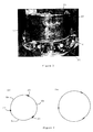
- Figure 3 shows a view of the cylindrical liner 6.
- the elastic straps (not shown) sit in grooves 21 at the axially upper and lower ends of the liner.
- the straps exert a contracting force on the liner which urges the liner inwards.
- the contraction is assisted by the three circumferentially spaced slits 22 (only two of which are shown in Figure 3 ) which extend in the axial direction and divide the liner into three portions. On deflation, the slits allow the three liner portions to slide over each other.
- the straps and the slits enable the liner and tubes to contract to a diameter less than that of the inner wall of the casing into which they are to be inserted, and less than the deflated tubes would otherwise have in the absence of the liner.
- the liner may also have spacing elements, such as ties extending across the slits, which ensure that on inflation the liner portions adopt an appropriate circumferential spacing.
- Figures 4(a) and (b) are end-on schematic views of the liner of Figure 3 in respectively its collapsed and expanded states and show spacing ties 23 connecting the liner portions 6a-c.
- the tubes and liner are attached to the column 5.
- the tubes and liner may be permanently attached to the column.
- the tubes are deflated so that the tubes and liner shrink to a diameter smaller than that of the bore of the casing.
- the casing is vertically loaded onto the fixture, dropping over the tubes, liner and column.
- the casing is restrained by clamping onto the base plate and the tubes can then be inflated.
- the force generated by inflating is greater than the resistance of the elastic straps so that the tubes and liner expand and the liner presses against the inner surface of the casing.
- the fixture can be used in conjunction with cylindrical components which have narrow through-openings, or with shell components which no through-opening at all.
Description
- The present invention relates to a fixture for securing a thin-walled component, such as a rocket nose cone or a gas turbine aero-engine casing.
-
WO 2008/107672 discloses an adaptive fixture for thin-walled components, for the purpose of enabling them to be machined with sufficient supporting rigidity and dynamic stability so as to maintain machining precision and surface finish to an acceptable engineering standard. The fixture has an inflatable elastomeric pressure element and a liner which fits between the pressure element and the component. It is particularly applicable to thin-walled components where secure fixture and vibration avoidance during machining is otherwise difficult to achieve. - The thin-walled component may have minor openings and an uneven internal/external surface without changing its character. Such a component is difficult to hold while it is machined. The thin wall lacks sufficient static rigidity and dynamic stability to withstand the cutting force generated in the machining process. The thin wall can become dynamically unstable and liable to vibrate, causing machining precision problems, mainly from the insufficient supporting rigidity. Surface finish problems can also result from the unstable self-excited vibration (known as "chatter") between the cutting-tool and workpiece.
- Examples of components which can benefit from the fixture of
WO 2008/107672 are gas turbine aero-engine casings and rocket nose cones. Such components are often made from difficult-to-machine material, such as heat-resistant alloy, and there is also a need to reduce component mass. However, in order to provide interfaces for connection of other components, machining work is usually inevitable. - For machining outer surfaces of thin-walled cylindrical components, the component is clamped at one end to a base of the fixture of
WO 2008/107672 . The pressure element and liner of the fixture are then positioned inside the component via the opening at the other end of the component, with the liner being located in the component first and the pressure element second. However, a problem can arise that it is difficult to position the pressure element and liner inside the component using this procedure when access to the internal space of the component is restricted. Indeed, positioning using the procedure can be impossible when the component is, for example, dome-shaped rather than cylindrical and the only major opening to the interior of the component is blocked by the fixture base. - Thus, in a first aspect, the present invention provides a fixture for securing a thin-walled component, the fixture including: a support having one or more securing devices for securing the component to the support, an inflatable pressure element which, in use, is positioned within the secured component and is adapted to press outwardly, when inflated, against a flexible liner, being adapted to fit between the pressure element and an inner thin wall of the component, wherein the liner has one or more elastic members which bias the liner against the outward expansion of the inflated pressure element and the inflated pressure element and the liner damp vibrations in the component during machining of an outer side of the thin wall, characterised in that: the flexible liner has slits which assist the liner to collapse with the pressure element when the pressure element is deflated.
- By a "thin-walled component" we mean a component having one or more thin walls. When such a wall is loaded, transverse shear stresses across the wall are generally insignificant relative to stretching and/or bending stresses in the plane of the wall. The thin wall typically lacks sufficient static rigidity to withstand cutting forces generated in machining operations, becoming dynamically unstable and liable to vibrate.
- By a "cylindrical component" we mean a hollow tubular structure having a through-opening. Such a cylindrical component may approximate to a true cylinder, or may, for example, be more frustoconical in shape. By a "shell component", we mean a bowl-like structure having a single major opening. Such a shell component may be shaped, for example, like a cone or a dome.
- Typically, in use, the liner is fitted to the deflated pressure element and pre-positioned on the support before the component is itself moved onto the support. Thus, advantageously, the liner, having one or more elastic members which bias the liner against the outward expansion of the inflated pressure element, facilitate the location and the removal of the liner and pressure element when access to the internal space of the component is restricted. For example, the one or more elastic members can reduce the diameter of the pressure element when the pressure element is deflated. That is, they can reduce the diameter the deflated pressure element further than its diameter would be in the absence of the liner.
- Typically, the inflatable pressure element is an inflatable elastomeric pressure element. Conveniently, the pressure element is inflated pneumatically. However, it may be inflated by any suitable fluid or gel. The fixture may have more than one pressure element.
- Preferably, the support has a retaining element which retains the pressure element in position within the secured component. The pressure element may be a tubular pressure element. For example, the retaining element may extend through the central hole of such a tubular pressure element. In use, the retaining element, component and pressure element may then be concentrically arranged with the pressure element between the retaining element and the component. Typically the liner encircles the pressure element. For example, when the pressure element is a tubular pressure element, the liner may be a cylinder that extends around the circumference of the pressure element.
- Preferably, the or each elastic member is an elongate member which extends around the liner, eg circumferentially around a cylindrical liner. When the pressure element is a tubular pressure element, the fixture may have two or more elastic elongate members which extend around the liner and are axially spaced along the axis of the tubular pressure element, eg an elongate member may be positioned at either axial end of a cylindrical liner.
- Preferably, when the pressure element is a tubular pressure element, the slits may extend in the axial direction of the tubular pressure element.
- The component may be a rocket nose cone or a gas turbine aero-engine casing.
- The component may have a cavity in which the pressure element and the flexible liner are positioned, and a neck region through which the pressure element and the flexible liner are inserted to arrive in the cavity, the neck region being narrower than the cavity. That is, the fixture can advantageously be used to position the pressure element and the liner in components with restrictive geometries.
- Embodiments of the invention will now be described by way of example with reference to the accompanying drawings in which:
-
Figure 1 shows a fixture for the external machining of a thin-walled cylindrical component; -
Figure 2(a) shows a side view of a gas turbine aero-engine casing 10, andFigure 2(b) is a perspective view looking towards the narrower end of the casing; -
Figure 3 shows a view of a liner for a fixture such as that shown inFigure 1 ; and -
Figures 4(a) and (b) are end-on schematic views of the liner ofFigure 3 in respectively its collapsed and expanded states. -
Figure 1 shows afixture 100 for the external machining of a thin-walledcylindrical component 10. The fixture comprises a mounting base support 1 in the form of a thick-walled plate having mountingholes 2 for connection to a machine table (not shown) of a machining centre (not shown). Securing devices (pins 3 and clamps 4) locate and clamp thecomponent 10 to the base 1. - A thick-walled rigid arbour or
column 5 providing an annular retaining surface is fixed centrally to the base 1 by bolts (not shown). Thearbour 5 terminates with a flange to connect to a thick-walled lid 12. Two modified vehicle-wheelinner tubes 8, having an internal radius R corresponding with the radius of thearbour 5, are fitted on the arbour. Being made of elastomeric, resiliently flexible material, thetubes 8 can be inflated to fit the enclosure confined within thecylindrical component 10, supportarbour 5, mounting base 1 andlid 12. Eachtube 8 has its ownair inlet valve 9 on its inner surface, and this is fitted through a respective aperture provided for this purpose on thearbour 5. Eachinlet valve 9 is extendable upwardly through the arbour, which is hollow. - A cylindrical flexible liner 6 (only a portion of which is shown in
Figure 1 ) wraps around thetubes 8 and spreads a uniform supporting pressure to provide dynamic damping normal to the component surface to be machined.Regional enhancements 7 can be incorporated in the liner. - The
lid 12 is a thick-walled circular plate provided with a wedged step (not shown) around its circumference to hold the top end of the cylindrical component.Lid 12 is also provided withholes 11 by which it can be attached to the top end of theinternal arbour 5 by bolts (not shown). - Conventionally, in order to secure the
component 10 to the fixture, the component would first be attached to the base support 1 using thepins 3 andclamps 4. After the component has been securely clamped, theflexible liner 6, followed by thetubes 8 would be dropped into the gap between thecentral column 5 and the inner wall of the component. Finally, thelid 12 would be attached and the tubes inflated. - However, this assembly procedure is typically only possible if the component being secured has a relatively unimpeded through-opening.
Figure 2(a) shows a side view of a component which is a gas turbine aero-engine casing 10. The extent of the thin side wall which it is desired to machine and therefore to support with the fixture is indicated by the double-headed arrow. The casing is substantially frustoconical in shape, and for reasons of stability it is desired to clamp the casing with the wider end of the casing downwards. However, as shown byFigure 2(b) , which is a perspective view looking towards the narrower end of the casing, the inner geometry of the casing has aneck region 20 at the narrower end which precludes loading the liner and tubes through the top of the casing. - Therefore, in order to secure the casing shown in
Figures 2(a) and (b) , the fixture has further features which allow vertical loading of the part onto the base support 1, with theliner 6 andtubes 8 already assembled and position on the support. In particular, the liner has elastic straps which bias the liner against the outward expansion of the inflated tubes. The straps also reduce the diameters of the tubes when the tubes are deflated. The liner further has slits which assist the liner to collapse. -
Figure 3 shows a view of thecylindrical liner 6. The elastic straps (not shown) sit ingrooves 21 at the axially upper and lower ends of the liner. The straps exert a contracting force on the liner which urges the liner inwards. The contraction is assisted by the three circumferentially spaced slits 22 (only two of which are shown inFigure 3 ) which extend in the axial direction and divide the liner into three portions. On deflation, the slits allow the three liner portions to slide over each other. Thus together the straps and the slits enable the liner and tubes to contract to a diameter less than that of the inner wall of the casing into which they are to be inserted, and less than the deflated tubes would otherwise have in the absence of the liner. - The liner may also have spacing elements, such as ties extending across the slits, which ensure that on inflation the liner portions adopt an appropriate circumferential spacing.
Figures 4(a) and (b) are end-on schematic views of the liner ofFigure 3 in respectively its collapsed and expanded states and show spacing ties 23 connecting theliner portions 6a-c. - To secure the
casing 10 to the fixture, firstly, the tubes and liner are attached to thecolumn 5. Indeed, the tubes and liner may be permanently attached to the column. The tubes are deflated so that the tubes and liner shrink to a diameter smaller than that of the bore of the casing. The casing is vertically loaded onto the fixture, dropping over the tubes, liner and column. The casing is restrained by clamping onto the base plate and the tubes can then be inflated. The force generated by inflating is greater than the resistance of the elastic straps so that the tubes and liner expand and the liner presses against the inner surface of the casing. - To remove the casing from the fixture after machining, the securing procedure can simply be reversed.
- In this way, the fixture can be used in conjunction with cylindrical components which have narrow through-openings, or with shell components which no through-opening at all.
- Although the present invention has been described in
Figures 1 to 4 in relation to a component such as an aero-engine casing, it is applicable to the machining of many other thin walled components.
Claims (9)
- A fixture (100) for securing a thin-walled component (10), the fixture (100) including:a support (1) having one or more securing devices (3,4) for securing the component (10) to the support (1),an inflatable pressure element (8) which, in use, is positioned within the secured component (10) and is adapted to press outwardly, when inflated, against a flexible liner (6),being adapted to fit between the pressure element (8) and an inner thin wall of the component (10),wherein the liner (6) has one or more elastic members which bias the liner (6) against the outward expansion of the inflated pressure element (8) and the inflated pressure element (8) and the liner (6) damp vibrations in the component (10) during machining of an outer side of the thin wall,characterised in that:the flexible liner (6) has slits (22) which assist the liner (6) to collapse with the pressure element (8) when the pressure element (8) is deflated.
- A fixture (100) according to claim 1, characterised in that the one or more elastic members reduce the diameter of the pressure element (8) when the pressure element (8) is deflated.
- A fixture (100) according claim 1 or 2,characterised in that the or each elastic member is an elongate member which extends around the liner (6).
- A fixture (100) according to any one of the previous claims, characterised in that the pressure element (8) is a tubular pressure element.
- A fixture (100) according to claim 4 when dependent on claim 3 characterised in that two or more elongate members extend around the liner (6) and are axially spaced along the axis of the tubular pressure element (8).
- A fixture (100) according to claim 4, characterised in that the slits (22) extend in the axial direction of the tubular pressure element between portions (6a, 6b, 6c).
- A fixture according to claim 6, characterised in that in the collapsed configuration the portions partially overlap adjacent portions.
- A fixture according to claim 6 or claim 7, wherein the portions are connected by spacing ties 23.
- A fixture (100) according to any one of the previous claims, characterised in that the component (10) is a rocket nose cone or a gas turbine aero-engine casing.
Applications Claiming Priority (2)
| Application Number | Priority Date | Filing Date | Title |
|---|---|---|---|
| GBGB0902791.3A GB0902791D0 (en) | 2009-02-20 | 2009-02-20 | Fixture for securing a thin-walled component |
| PCT/EP2010/000406 WO2010094382A1 (en) | 2009-02-20 | 2010-01-25 | Fixture for securing a thin-walled component, comprising a liner with one or more elastic members |
Publications (2)
| Publication Number | Publication Date |
|---|---|
| EP2398623A1 EP2398623A1 (en) | 2011-12-28 |
| EP2398623B1 true EP2398623B1 (en) | 2013-03-13 |
Family
ID=40565365
Family Applications (1)
| Application Number | Title | Priority Date | Filing Date |
|---|---|---|---|
| EP10702049A Active EP2398623B1 (en) | 2009-02-20 | 2010-01-25 | Fixture for securing a thin-walled component, comprising a liner with one or more elastic members and slits |
Country Status (7)
| Country | Link |
|---|---|
| US (1) | US9085057B2 (en) |
| EP (1) | EP2398623B1 (en) |
| JP (2) | JP5829126B2 (en) |
| KR (1) | KR101705767B1 (en) |
| ES (1) | ES2401745T3 (en) |
| GB (1) | GB0902791D0 (en) |
| WO (1) | WO2010094382A1 (en) |
Cited By (1)
| Publication number | Priority date | Publication date | Assignee | Title |
|---|---|---|---|---|
| CN109128896A (en) * | 2017-06-15 | 2019-01-04 | 韩华航空航天公司 | Fixed device and the method for manufacturing the elastic component in fixed device |
Families Citing this family (21)
| Publication number | Priority date | Publication date | Assignee | Title |
|---|---|---|---|---|
| GB2447278B (en) * | 2007-03-06 | 2011-12-07 | Univ Sheffield | Adaptive design of fixture for thin-walled shell/cylindrical components |
| CN103350357A (en) * | 2013-07-02 | 2013-10-16 | 哈尔滨汽轮机厂有限责任公司 | Gas turbine flame tube positioning clamping device |
| GB201402290D0 (en) * | 2014-02-11 | 2014-03-26 | Rolls Royce Plc | Fixture |
| ES2489442B1 (en) * | 2014-03-25 | 2015-04-28 | Talleres Lujambio, S.L. | Anti-dome system for hollow shaft machining |
| CN104476245A (en) * | 2014-11-10 | 2015-04-01 | 沈阳黎明航空发动机(集团)有限责任公司 | Assembling method and device for thin-wall box |
| GB201420246D0 (en) * | 2014-11-14 | 2014-12-31 | Rolls Royce Plc | Apparatus for damping machining vibrations |
| GB201501461D0 (en) | 2015-01-29 | 2015-03-18 | Rolls Royce Plc | Apparatus for damping machining vibration of an object |
| CN105345054B (en) * | 2015-11-26 | 2018-05-29 | 中国南方航空工业(集团)有限公司 | Quick-release type universal fixturing |
| CN107127619B (en) * | 2017-06-30 | 2023-05-02 | 天津天海同步科技有限公司 | High-precision synchronizer gear ring hot post-processing grooving clamp |
| CN109623443B (en) * | 2019-01-24 | 2021-03-16 | 天津大学 | Clamp suitable for mirror-image milling of curved-surface thin-plate parts |
| GB2583505B (en) * | 2019-04-30 | 2021-11-10 | The Unique Puck Company | Multi-functional carrier puck |
| CN110091197B (en) * | 2019-06-14 | 2020-10-02 | 西南石油大学 | Device and method for automatically inhibiting milling vibration of thin-wall revolving body |
| CN111702686B (en) * | 2020-08-20 | 2020-11-10 | 湖南工业职业技术学院 | Special-shaped part clamping is with adding clamping apparatus |
| CN112247636A (en) * | 2020-10-15 | 2021-01-22 | 中国兵器工业集团航空弹药研究院有限公司 | Positioning and clamping tool for shell parts |
| CN112122978A (en) * | 2020-10-16 | 2020-12-25 | 浙江华朔科技股份有限公司 | Motor casing clamp for new energy automobile |
| CN112518275B (en) * | 2020-11-30 | 2022-03-25 | 杭州徐睿机械有限公司 | Thin-wall piece expansion-clamping type face-identifying angle-searching mechanism and implementation method thereof |
| CN113369532A (en) * | 2021-06-29 | 2021-09-10 | 贵州航天电子科技有限公司 | A side direction hole processingequipment for frame part |
| CN114161315B (en) * | 2021-12-03 | 2023-01-10 | 北京航星机器制造有限公司 | Inner support device and inner support machining method for thin-wall part |
| CN114406784B (en) * | 2021-12-20 | 2023-09-22 | 彩虹显示器件股份有限公司 | Method for avoiding vibration during processing of thin-wall welding assembly |
| US11732614B2 (en) * | 2021-12-27 | 2023-08-22 | Pratt & Whitney Canada Corp. | Gas turbine engine case fixture assembly with platform adaptor |
| CN115121846B (en) * | 2022-09-01 | 2022-11-18 | 北京成立科技有限公司 | Aerospace engine casing machining device and method |
Family Cites Families (7)
| Publication number | Priority date | Publication date | Assignee | Title |
|---|---|---|---|---|
| LU31181A1 (en) * | 1950-02-10 | |||
| US4200301A (en) * | 1978-09-05 | 1980-04-29 | JRC Products Inc. | Core locking device |
| US4953877A (en) * | 1988-09-23 | 1990-09-04 | Gene Slachta | Fluid actuated chuck |
| US5840386A (en) * | 1996-02-22 | 1998-11-24 | Praxair S.T. Technology, Inc. | Sleeve for a liquid transfer roll and method for producing it |
| US6015154A (en) * | 1998-05-28 | 2000-01-18 | Hydra-Lock Corporation | Large displacement hydrostatic workpiece holder |
| US7147232B2 (en) * | 2003-06-30 | 2006-12-12 | Hydra-Lock Corporation | Workpiece holder |
| GB2447278B (en) | 2007-03-06 | 2011-12-07 | Univ Sheffield | Adaptive design of fixture for thin-walled shell/cylindrical components |
-
2009
- 2009-02-20 GB GBGB0902791.3A patent/GB0902791D0/en not_active Ceased
-
2010
- 2010-01-25 KR KR1020117021956A patent/KR101705767B1/en active IP Right Grant
- 2010-01-25 JP JP2011550441A patent/JP5829126B2/en active Active
- 2010-01-25 ES ES10702049T patent/ES2401745T3/en active Active
- 2010-01-25 EP EP10702049A patent/EP2398623B1/en active Active
- 2010-01-25 US US13/148,597 patent/US9085057B2/en active Active
- 2010-01-25 WO PCT/EP2010/000406 patent/WO2010094382A1/en active Application Filing
-
2014
- 2014-12-08 JP JP2014248378A patent/JP2015128815A/en not_active Withdrawn
Cited By (1)
| Publication number | Priority date | Publication date | Assignee | Title |
|---|---|---|---|---|
| CN109128896A (en) * | 2017-06-15 | 2019-01-04 | 韩华航空航天公司 | Fixed device and the method for manufacturing the elastic component in fixed device |
Also Published As
| Publication number | Publication date |
|---|---|
| ES2401745T3 (en) | 2013-04-24 |
| JP2015128815A (en) | 2015-07-16 |
| JP2012518547A (en) | 2012-08-16 |
| KR20110128881A (en) | 2011-11-30 |
| EP2398623A1 (en) | 2011-12-28 |
| WO2010094382A1 (en) | 2010-08-26 |
| GB0902791D0 (en) | 2009-04-08 |
| US9085057B2 (en) | 2015-07-21 |
| US20120133103A1 (en) | 2012-05-31 |
| JP5829126B2 (en) | 2015-12-09 |
| KR101705767B1 (en) | 2017-02-10 |
Similar Documents
| Publication | Publication Date | Title |
|---|---|---|
| EP2398623B1 (en) | Fixture for securing a thin-walled component, comprising a liner with one or more elastic members and slits | |
| EP2398622B1 (en) | Fixture for securing a thin-walled component comprising a liner having a stiffening element | |
| AU2008223652B2 (en) | Adaptive design of fixture for thin-walled shell/cylindrical components | |
| KR101656473B1 (en) | Jig for pipe | |
| JP2009507652A (en) | Tool holder with less vibration | |
| JP2009279745A (en) | Clamp device | |
| JP2009501644A (en) | Clamping device | |
| US20070296132A1 (en) | Machining fixture for centering and holding workpiece | |
| JP2005532919A (en) | Mechanical hydraulic clamping device | |
| US20160325360A1 (en) | Apparatus for retaining a workpiece, and methods of use and manufacture thereof | |
| SE525778C2 (en) | Hydromechanical clamping device with expansion means with cooperating cones | |
| US20210362296A1 (en) | Truing device for circular tools and method for mounting/removing circular tools | |
| JP7377868B2 (en) | Hydraulic clamp device and collar member | |
| CN114434185A (en) | Device for stabilizing a workpiece in a machine tool | |
| CN110682120A (en) | Positioning and supporting device for machining thin-wall shell parts | |
| CN217991693U (en) | Port supporting device for internal turning of rocket tank bottom | |
| CN116673760A (en) | Liquid and air bag vibration-proof supporting device and processing method for thin-wall part | |
| JP2008018474A (en) | Fixing device for cylindrical workpiece | |
| JPH04219571A (en) | Device for cover fitting to pressure vessel |
Legal Events
| Date | Code | Title | Description |
|---|---|---|---|
| PUAI | Public reference made under article 153(3) epc to a published international application that has entered the european phase |
Free format text: ORIGINAL CODE: 0009012 |
|
| 17P | Request for examination filed |
Effective date: 20110805 |
|
| AK | Designated contracting states |
Kind code of ref document: A1 Designated state(s): AT BE BG CH CY CZ DE DK EE ES FI FR GB GR HR HU IE IS IT LI LT LU LV MC MK MT NL NO PL PT RO SE SI SK SM TR |
|
| DAX | Request for extension of the european patent (deleted) | ||
| 17Q | First examination report despatched |
Effective date: 20120525 |
|
| REG | Reference to a national code |
Ref country code: DE Ref legal event code: R079 Ref document number: 602010005448 Country of ref document: DE Free format text: PREVIOUS MAIN CLASS: B23Q0003060000 Ipc: B23Q0003080000 |
|
| GRAP | Despatch of communication of intention to grant a patent |
Free format text: ORIGINAL CODE: EPIDOSNIGR1 |
|
| RIC1 | Information provided on ipc code assigned before grant |
Ipc: B23Q 3/08 20060101AFI20121018BHEP |
|
| GRAS | Grant fee paid |
Free format text: ORIGINAL CODE: EPIDOSNIGR3 |
|
| GRAA | (expected) grant |
Free format text: ORIGINAL CODE: 0009210 |
|
| AK | Designated contracting states |
Kind code of ref document: B1 Designated state(s): AT BE BG CH CY CZ DE DK EE ES FI FR GB GR HR HU IE IS IT LI LT LU LV MC MK MT NL NO PL PT RO SE SI SK SM TR |
|
| REG | Reference to a national code |
Ref country code: GB Ref legal event code: FG4D |
|
| REG | Reference to a national code |
Ref country code: CH Ref legal event code: EP Ref country code: AT Ref legal event code: REF Ref document number: 600488 Country of ref document: AT Kind code of ref document: T Effective date: 20130315 |
|
| REG | Reference to a national code |
Ref country code: IE Ref legal event code: FG4D |
|
| REG | Reference to a national code |
Ref country code: ES Ref legal event code: FG2A Ref document number: 2401745 Country of ref document: ES Kind code of ref document: T3 Effective date: 20130424 |
|
| REG | Reference to a national code |
Ref country code: DE Ref legal event code: R096 Ref document number: 602010005448 Country of ref document: DE Effective date: 20130508 |
|
| PG25 | Lapsed in a contracting state [announced via postgrant information from national office to epo] |
Ref country code: LT Free format text: LAPSE BECAUSE OF FAILURE TO SUBMIT A TRANSLATION OF THE DESCRIPTION OR TO PAY THE FEE WITHIN THE PRESCRIBED TIME-LIMIT Effective date: 20130313 Ref country code: NO Free format text: LAPSE BECAUSE OF FAILURE TO SUBMIT A TRANSLATION OF THE DESCRIPTION OR TO PAY THE FEE WITHIN THE PRESCRIBED TIME-LIMIT Effective date: 20130613 Ref country code: SE Free format text: LAPSE BECAUSE OF FAILURE TO SUBMIT A TRANSLATION OF THE DESCRIPTION OR TO PAY THE FEE WITHIN THE PRESCRIBED TIME-LIMIT Effective date: 20130313 Ref country code: BG Free format text: LAPSE BECAUSE OF FAILURE TO SUBMIT A TRANSLATION OF THE DESCRIPTION OR TO PAY THE FEE WITHIN THE PRESCRIBED TIME-LIMIT Effective date: 20130613 |
|
| REG | Reference to a national code |
Ref country code: AT Ref legal event code: MK05 Ref document number: 600488 Country of ref document: AT Kind code of ref document: T Effective date: 20130313 |
|
| REG | Reference to a national code |
Ref country code: NL Ref legal event code: VDEP Effective date: 20130313 |
|
| REG | Reference to a national code |
Ref country code: LT Ref legal event code: MG4D |
|
| PG25 | Lapsed in a contracting state [announced via postgrant information from national office to epo] |
Ref country code: LV Free format text: LAPSE BECAUSE OF FAILURE TO SUBMIT A TRANSLATION OF THE DESCRIPTION OR TO PAY THE FEE WITHIN THE PRESCRIBED TIME-LIMIT Effective date: 20130313 Ref country code: FI Free format text: LAPSE BECAUSE OF FAILURE TO SUBMIT A TRANSLATION OF THE DESCRIPTION OR TO PAY THE FEE WITHIN THE PRESCRIBED TIME-LIMIT Effective date: 20130313 Ref country code: SI Free format text: LAPSE BECAUSE OF FAILURE TO SUBMIT A TRANSLATION OF THE DESCRIPTION OR TO PAY THE FEE WITHIN THE PRESCRIBED TIME-LIMIT Effective date: 20130313 Ref country code: GR Free format text: LAPSE BECAUSE OF FAILURE TO SUBMIT A TRANSLATION OF THE DESCRIPTION OR TO PAY THE FEE WITHIN THE PRESCRIBED TIME-LIMIT Effective date: 20130614 |
|
| PG25 | Lapsed in a contracting state [announced via postgrant information from national office to epo] |
Ref country code: HR Free format text: LAPSE BECAUSE OF FAILURE TO SUBMIT A TRANSLATION OF THE DESCRIPTION OR TO PAY THE FEE WITHIN THE PRESCRIBED TIME-LIMIT Effective date: 20130313 Ref country code: BE Free format text: LAPSE BECAUSE OF FAILURE TO SUBMIT A TRANSLATION OF THE DESCRIPTION OR TO PAY THE FEE WITHIN THE PRESCRIBED TIME-LIMIT Effective date: 20130313 |
|
| PG25 | Lapsed in a contracting state [announced via postgrant information from national office to epo] |
Ref country code: IS Free format text: LAPSE BECAUSE OF FAILURE TO SUBMIT A TRANSLATION OF THE DESCRIPTION OR TO PAY THE FEE WITHIN THE PRESCRIBED TIME-LIMIT Effective date: 20130713 Ref country code: PT Free format text: LAPSE BECAUSE OF FAILURE TO SUBMIT A TRANSLATION OF THE DESCRIPTION OR TO PAY THE FEE WITHIN THE PRESCRIBED TIME-LIMIT Effective date: 20130715 Ref country code: AT Free format text: LAPSE BECAUSE OF FAILURE TO SUBMIT A TRANSLATION OF THE DESCRIPTION OR TO PAY THE FEE WITHIN THE PRESCRIBED TIME-LIMIT Effective date: 20130313 Ref country code: CZ Free format text: LAPSE BECAUSE OF FAILURE TO SUBMIT A TRANSLATION OF THE DESCRIPTION OR TO PAY THE FEE WITHIN THE PRESCRIBED TIME-LIMIT Effective date: 20130313 Ref country code: RO Free format text: LAPSE BECAUSE OF FAILURE TO SUBMIT A TRANSLATION OF THE DESCRIPTION OR TO PAY THE FEE WITHIN THE PRESCRIBED TIME-LIMIT Effective date: 20130313 Ref country code: EE Free format text: LAPSE BECAUSE OF FAILURE TO SUBMIT A TRANSLATION OF THE DESCRIPTION OR TO PAY THE FEE WITHIN THE PRESCRIBED TIME-LIMIT Effective date: 20130313 Ref country code: NL Free format text: LAPSE BECAUSE OF FAILURE TO SUBMIT A TRANSLATION OF THE DESCRIPTION OR TO PAY THE FEE WITHIN THE PRESCRIBED TIME-LIMIT Effective date: 20130313 Ref country code: SK Free format text: LAPSE BECAUSE OF FAILURE TO SUBMIT A TRANSLATION OF THE DESCRIPTION OR TO PAY THE FEE WITHIN THE PRESCRIBED TIME-LIMIT Effective date: 20130313 |
|
| PG25 | Lapsed in a contracting state [announced via postgrant information from national office to epo] |
Ref country code: PL Free format text: LAPSE BECAUSE OF FAILURE TO SUBMIT A TRANSLATION OF THE DESCRIPTION OR TO PAY THE FEE WITHIN THE PRESCRIBED TIME-LIMIT Effective date: 20130313 |
|
| PLBE | No opposition filed within time limit |
Free format text: ORIGINAL CODE: 0009261 |
|
| STAA | Information on the status of an ep patent application or granted ep patent |
Free format text: STATUS: NO OPPOSITION FILED WITHIN TIME LIMIT |
|
| PG25 | Lapsed in a contracting state [announced via postgrant information from national office to epo] |
Ref country code: DK Free format text: LAPSE BECAUSE OF FAILURE TO SUBMIT A TRANSLATION OF THE DESCRIPTION OR TO PAY THE FEE WITHIN THE PRESCRIBED TIME-LIMIT Effective date: 20130313 |
|
| 26N | No opposition filed |
Effective date: 20131216 |
|
| PG25 | Lapsed in a contracting state [announced via postgrant information from national office to epo] |
Ref country code: IT Free format text: LAPSE BECAUSE OF FAILURE TO SUBMIT A TRANSLATION OF THE DESCRIPTION OR TO PAY THE FEE WITHIN THE PRESCRIBED TIME-LIMIT Effective date: 20130313 |
|
| REG | Reference to a national code |
Ref country code: DE Ref legal event code: R097 Ref document number: 602010005448 Country of ref document: DE Effective date: 20131216 |
|
| PG25 | Lapsed in a contracting state [announced via postgrant information from national office to epo] |
Ref country code: LU Free format text: LAPSE BECAUSE OF FAILURE TO SUBMIT A TRANSLATION OF THE DESCRIPTION OR TO PAY THE FEE WITHIN THE PRESCRIBED TIME-LIMIT Effective date: 20140125 |
|
| REG | Reference to a national code |
Ref country code: CH Ref legal event code: PL |
|
| PG25 | Lapsed in a contracting state [announced via postgrant information from national office to epo] |
Ref country code: CH Free format text: LAPSE BECAUSE OF NON-PAYMENT OF DUE FEES Effective date: 20140131 Ref country code: LI Free format text: LAPSE BECAUSE OF NON-PAYMENT OF DUE FEES Effective date: 20140131 |
|
| REG | Reference to a national code |
Ref country code: IE Ref legal event code: MM4A |
|
| REG | Reference to a national code |
Ref country code: DE Ref legal event code: R082 Ref document number: 602010005448 Country of ref document: DE Representative=s name: FLEUCHAUS & GALLO PARTNERSCHAFT MBB, DE |
|
| PG25 | Lapsed in a contracting state [announced via postgrant information from national office to epo] |
Ref country code: IE Free format text: LAPSE BECAUSE OF NON-PAYMENT OF DUE FEES Effective date: 20140125 |
|
| PG25 | Lapsed in a contracting state [announced via postgrant information from national office to epo] |
Ref country code: MC Free format text: LAPSE BECAUSE OF FAILURE TO SUBMIT A TRANSLATION OF THE DESCRIPTION OR TO PAY THE FEE WITHIN THE PRESCRIBED TIME-LIMIT Effective date: 20130313 |
|
| REG | Reference to a national code |
Ref country code: FR Ref legal event code: PLFP Year of fee payment: 7 |
|
| PG25 | Lapsed in a contracting state [announced via postgrant information from national office to epo] |
Ref country code: MT Free format text: LAPSE BECAUSE OF FAILURE TO SUBMIT A TRANSLATION OF THE DESCRIPTION OR TO PAY THE FEE WITHIN THE PRESCRIBED TIME-LIMIT Effective date: 20130313 |
|
| PG25 | Lapsed in a contracting state [announced via postgrant information from national office to epo] |
Ref country code: SM Free format text: LAPSE BECAUSE OF FAILURE TO SUBMIT A TRANSLATION OF THE DESCRIPTION OR TO PAY THE FEE WITHIN THE PRESCRIBED TIME-LIMIT Effective date: 20130313 |
|
| PG25 | Lapsed in a contracting state [announced via postgrant information from national office to epo] |
Ref country code: CY Free format text: LAPSE BECAUSE OF FAILURE TO SUBMIT A TRANSLATION OF THE DESCRIPTION OR TO PAY THE FEE WITHIN THE PRESCRIBED TIME-LIMIT Effective date: 20130313 |
|
| PG25 | Lapsed in a contracting state [announced via postgrant information from national office to epo] |
Ref country code: HU Free format text: LAPSE BECAUSE OF FAILURE TO SUBMIT A TRANSLATION OF THE DESCRIPTION OR TO PAY THE FEE WITHIN THE PRESCRIBED TIME-LIMIT; INVALID AB INITIO Effective date: 20100125 Ref country code: TR Free format text: LAPSE BECAUSE OF FAILURE TO SUBMIT A TRANSLATION OF THE DESCRIPTION OR TO PAY THE FEE WITHIN THE PRESCRIBED TIME-LIMIT Effective date: 20130313 |
|
| REG | Reference to a national code |
Ref country code: FR Ref legal event code: PLFP Year of fee payment: 8 |
|
| REG | Reference to a national code |
Ref country code: FR Ref legal event code: CA Effective date: 20170517 |
|
| REG | Reference to a national code |
Ref country code: FR Ref legal event code: PLFP Year of fee payment: 9 |
|
| PG25 | Lapsed in a contracting state [announced via postgrant information from national office to epo] |
Ref country code: MK Free format text: LAPSE BECAUSE OF FAILURE TO SUBMIT A TRANSLATION OF THE DESCRIPTION OR TO PAY THE FEE WITHIN THE PRESCRIBED TIME-LIMIT Effective date: 20130313 |
|
| REG | Reference to a national code |
Ref country code: DE Ref legal event code: R082 Ref document number: 602010005448 Country of ref document: DE Representative=s name: FLEUCHAUS & GALLO PARTNERSCHAFT MBB - PATENT- , DE Ref country code: DE Ref legal event code: R082 Ref document number: 602010005448 Country of ref document: DE Representative=s name: FLEUCHAUS & GALLO PARTNERSCHAFT MBB PATENTANWA, DE |
|
| PGFP | Annual fee paid to national office [announced via postgrant information from national office to epo] |
Ref country code: FR Payment date: 20230124 Year of fee payment: 14 Ref country code: ES Payment date: 20230228 Year of fee payment: 14 |
|
| PGFP | Annual fee paid to national office [announced via postgrant information from national office to epo] |
Ref country code: GB Payment date: 20230124 Year of fee payment: 14 Ref country code: DE Payment date: 20230127 Year of fee payment: 14 |
|
| P01 | Opt-out of the competence of the unified patent court (upc) registered |
Effective date: 20230528 |