EP2398121A2 - Aircraft conduit harness retention system - Google Patents
Aircraft conduit harness retention system Download PDFInfo
- Publication number
- EP2398121A2 EP2398121A2 EP11169663A EP11169663A EP2398121A2 EP 2398121 A2 EP2398121 A2 EP 2398121A2 EP 11169663 A EP11169663 A EP 11169663A EP 11169663 A EP11169663 A EP 11169663A EP 2398121 A2 EP2398121 A2 EP 2398121A2
- Authority
- EP
- European Patent Office
- Prior art keywords
- mating formation
- aircraft
- retention system
- conduit harness
- snap
- Prior art date
- Legal status (The legal status is an assumption and is not a legal conclusion. Google has not performed a legal analysis and makes no representation as to the accuracy of the status listed.)
- Withdrawn
Links
- 230000014759 maintenance of location Effects 0.000 title claims abstract description 27
- 230000015572 biosynthetic process Effects 0.000 claims description 37
- 238000005755 formation reaction Methods 0.000 claims description 37
- 230000013011 mating Effects 0.000 claims description 31
- 125000006850 spacer group Chemical group 0.000 abstract description 19
- 239000002826 coolant Substances 0.000 description 2
- 239000000446 fuel Substances 0.000 description 2
- 239000000463 material Substances 0.000 description 2
- 239000004033 plastic Substances 0.000 description 2
- 229920003023 plastic Polymers 0.000 description 2
- 239000000853 adhesive Substances 0.000 description 1
- 230000001070 adhesive effect Effects 0.000 description 1
- 238000004873 anchoring Methods 0.000 description 1
- 239000002184 metal Substances 0.000 description 1
Images


Classifications
-
- B—PERFORMING OPERATIONS; TRANSPORTING
- B64—AIRCRAFT; AVIATION; COSMONAUTICS
- B64C—AEROPLANES; HELICOPTERS
- B64C1/00—Fuselages; Constructional features common to fuselages, wings, stabilising surfaces or the like
- B64C1/40—Sound or heat insulation, e.g. using insulation blankets
- B64C1/403—Arrangement of fasteners specially adapted therefor, e.g. of clips
- B64C1/406—Arrangement of fasteners specially adapted therefor, e.g. of clips in combination with supports for lines, e.g. for pipes or cables
-
- F—MECHANICAL ENGINEERING; LIGHTING; HEATING; WEAPONS; BLASTING
- F16—ENGINEERING ELEMENTS AND UNITS; GENERAL MEASURES FOR PRODUCING AND MAINTAINING EFFECTIVE FUNCTIONING OF MACHINES OR INSTALLATIONS; THERMAL INSULATION IN GENERAL
- F16L—PIPES; JOINTS OR FITTINGS FOR PIPES; SUPPORTS FOR PIPES, CABLES OR PROTECTIVE TUBING; MEANS FOR THERMAL INSULATION IN GENERAL
- F16L3/00—Supports for pipes, cables or protective tubing, e.g. hangers, holders, clamps, cleats, clips, brackets
- F16L3/08—Supports for pipes, cables or protective tubing, e.g. hangers, holders, clamps, cleats, clips, brackets substantially surrounding the pipe, cable or protective tubing
- F16L3/12—Supports for pipes, cables or protective tubing, e.g. hangers, holders, clamps, cleats, clips, brackets substantially surrounding the pipe, cable or protective tubing comprising a member substantially surrounding the pipe, cable or protective tubing
- F16L3/123—Supports for pipes, cables or protective tubing, e.g. hangers, holders, clamps, cleats, clips, brackets substantially surrounding the pipe, cable or protective tubing comprising a member substantially surrounding the pipe, cable or protective tubing and extending along the attachment surface
-
- F—MECHANICAL ENGINEERING; LIGHTING; HEATING; WEAPONS; BLASTING
- F16—ENGINEERING ELEMENTS AND UNITS; GENERAL MEASURES FOR PRODUCING AND MAINTAINING EFFECTIVE FUNCTIONING OF MACHINES OR INSTALLATIONS; THERMAL INSULATION IN GENERAL
- F16L—PIPES; JOINTS OR FITTINGS FOR PIPES; SUPPORTS FOR PIPES, CABLES OR PROTECTIVE TUBING; MEANS FOR THERMAL INSULATION IN GENERAL
- F16L3/00—Supports for pipes, cables or protective tubing, e.g. hangers, holders, clamps, cleats, clips, brackets
- F16L3/08—Supports for pipes, cables or protective tubing, e.g. hangers, holders, clamps, cleats, clips, brackets substantially surrounding the pipe, cable or protective tubing
- F16L3/12—Supports for pipes, cables or protective tubing, e.g. hangers, holders, clamps, cleats, clips, brackets substantially surrounding the pipe, cable or protective tubing comprising a member substantially surrounding the pipe, cable or protective tubing
- F16L3/127—Supports for pipes, cables or protective tubing, e.g. hangers, holders, clamps, cleats, clips, brackets substantially surrounding the pipe, cable or protective tubing comprising a member substantially surrounding the pipe, cable or protective tubing and extending away from the attachment surface
-
- F—MECHANICAL ENGINEERING; LIGHTING; HEATING; WEAPONS; BLASTING
- F16—ENGINEERING ELEMENTS AND UNITS; GENERAL MEASURES FOR PRODUCING AND MAINTAINING EFFECTIVE FUNCTIONING OF MACHINES OR INSTALLATIONS; THERMAL INSULATION IN GENERAL
- F16L—PIPES; JOINTS OR FITTINGS FOR PIPES; SUPPORTS FOR PIPES, CABLES OR PROTECTIVE TUBING; MEANS FOR THERMAL INSULATION IN GENERAL
- F16L3/00—Supports for pipes, cables or protective tubing, e.g. hangers, holders, clamps, cleats, clips, brackets
- F16L3/08—Supports for pipes, cables or protective tubing, e.g. hangers, holders, clamps, cleats, clips, brackets substantially surrounding the pipe, cable or protective tubing
- F16L3/12—Supports for pipes, cables or protective tubing, e.g. hangers, holders, clamps, cleats, clips, brackets substantially surrounding the pipe, cable or protective tubing comprising a member substantially surrounding the pipe, cable or protective tubing
- F16L3/13—Supports for pipes, cables or protective tubing, e.g. hangers, holders, clamps, cleats, clips, brackets substantially surrounding the pipe, cable or protective tubing comprising a member substantially surrounding the pipe, cable or protective tubing and engaging it by snap action
-
- F—MECHANICAL ENGINEERING; LIGHTING; HEATING; WEAPONS; BLASTING
- F16—ENGINEERING ELEMENTS AND UNITS; GENERAL MEASURES FOR PRODUCING AND MAINTAINING EFFECTIVE FUNCTIONING OF MACHINES OR INSTALLATIONS; THERMAL INSULATION IN GENERAL
- F16L—PIPES; JOINTS OR FITTINGS FOR PIPES; SUPPORTS FOR PIPES, CABLES OR PROTECTIVE TUBING; MEANS FOR THERMAL INSULATION IN GENERAL
- F16L3/00—Supports for pipes, cables or protective tubing, e.g. hangers, holders, clamps, cleats, clips, brackets
- F16L3/22—Supports for pipes, cables or protective tubing, e.g. hangers, holders, clamps, cleats, clips, brackets specially adapted for supporting a number of parallel pipes at intervals
- F16L3/221—Supports for pipes, cables or protective tubing, e.g. hangers, holders, clamps, cleats, clips, brackets specially adapted for supporting a number of parallel pipes at intervals having brackets connected together by means of a common support
-
- F—MECHANICAL ENGINEERING; LIGHTING; HEATING; WEAPONS; BLASTING
- F16—ENGINEERING ELEMENTS AND UNITS; GENERAL MEASURES FOR PRODUCING AND MAINTAINING EFFECTIVE FUNCTIONING OF MACHINES OR INSTALLATIONS; THERMAL INSULATION IN GENERAL
- F16M—FRAMES, CASINGS OR BEDS OF ENGINES, MACHINES OR APPARATUS, NOT SPECIFIC TO ENGINES, MACHINES OR APPARATUS PROVIDED FOR ELSEWHERE; STANDS; SUPPORTS
- F16M13/00—Other supports for positioning apparatus or articles; Means for steadying hand-held apparatus or articles
- F16M13/02—Other supports for positioning apparatus or articles; Means for steadying hand-held apparatus or articles for supporting on, or attaching to, an object, e.g. tree, gate, window-frame, cycle
-
- H—ELECTRICITY
- H02—GENERATION; CONVERSION OR DISTRIBUTION OF ELECTRIC POWER
- H02G—INSTALLATION OF ELECTRIC CABLES OR LINES, OR OF COMBINED OPTICAL AND ELECTRIC CABLES OR LINES
- H02G3/00—Installations of electric cables or lines or protective tubing therefor in or on buildings, equivalent structures or vehicles
- H02G3/30—Installations of cables or lines on walls, floors or ceilings
- H02G3/32—Installations of cables or lines on walls, floors or ceilings using mounting clamps
-
- F—MECHANICAL ENGINEERING; LIGHTING; HEATING; WEAPONS; BLASTING
- F16—ENGINEERING ELEMENTS AND UNITS; GENERAL MEASURES FOR PRODUCING AND MAINTAINING EFFECTIVE FUNCTIONING OF MACHINES OR INSTALLATIONS; THERMAL INSULATION IN GENERAL
- F16L—PIPES; JOINTS OR FITTINGS FOR PIPES; SUPPORTS FOR PIPES, CABLES OR PROTECTIVE TUBING; MEANS FOR THERMAL INSULATION IN GENERAL
- F16L3/00—Supports for pipes, cables or protective tubing, e.g. hangers, holders, clamps, cleats, clips, brackets
- F16L3/22—Supports for pipes, cables or protective tubing, e.g. hangers, holders, clamps, cleats, clips, brackets specially adapted for supporting a number of parallel pipes at intervals
- F16L3/223—Supports for pipes, cables or protective tubing, e.g. hangers, holders, clamps, cleats, clips, brackets specially adapted for supporting a number of parallel pipes at intervals each support having one transverse base for supporting the pipes
- F16L3/227—Supports for pipes, cables or protective tubing, e.g. hangers, holders, clamps, cleats, clips, brackets specially adapted for supporting a number of parallel pipes at intervals each support having one transverse base for supporting the pipes each pipe being supported by a separate element fastened to the base
-
- F—MECHANICAL ENGINEERING; LIGHTING; HEATING; WEAPONS; BLASTING
- F16—ENGINEERING ELEMENTS AND UNITS; GENERAL MEASURES FOR PRODUCING AND MAINTAINING EFFECTIVE FUNCTIONING OF MACHINES OR INSTALLATIONS; THERMAL INSULATION IN GENERAL
- F16L—PIPES; JOINTS OR FITTINGS FOR PIPES; SUPPORTS FOR PIPES, CABLES OR PROTECTIVE TUBING; MEANS FOR THERMAL INSULATION IN GENERAL
- F16L3/00—Supports for pipes, cables or protective tubing, e.g. hangers, holders, clamps, cleats, clips, brackets
- F16L3/22—Supports for pipes, cables or protective tubing, e.g. hangers, holders, clamps, cleats, clips, brackets specially adapted for supporting a number of parallel pipes at intervals
- F16L3/237—Supports for pipes, cables or protective tubing, e.g. hangers, holders, clamps, cleats, clips, brackets specially adapted for supporting a number of parallel pipes at intervals for two pipes
Definitions
- the present invention relates to an aircraft conduit harness retention system. More particularly, the present invention relates to a snap-fit aircraft conduit harness retention system which permits multiple conduit harnesses to be mounted from a single mounting location.
- Wire looms in aircraft are commonly harnessed using P-clip harnesses.
- Such clips are constructed from strips of metal or plastics material formed in a loop to provide a wire loom receiving portion and a connection portion comprising a flat double-thickness flange.
- the flange will typically define a bore for the attachment of the P-clip harness to a component within the aircraft.
- an aircraft conduit harness retention system comprising a first part having an attachment portion for attachment to an aircraft component at a first end and a first mating formation at a second end, a second part having a second mating formation, wherein the first mating formation and the second mating formation are engageable via a snap-fit to retain a flange of a first conduit harness therebetween such that the conduit harness is offset from the aircraft component.
- an aircraft conduit harness retention system comprising a first part having an attachment portion for attachment to an aircraft component at a first end and a first mating formation at a second end, wherein the first mating formation is a snap-fit formation for attachment of a conduit harness.
- conduit harnesses such as P-clips can be offset such that more than two can be mounted to a single position on an aircraft component such as a fuselage, wing or empennage.
- a conduit harness retention system 100 is provided which comprises a base 102, a first spacer 104, a second spacer 106 and a cap 108.
- the harness retention system retains a first P-clip harness 110, a second P-clip harness 112, a third P-clip harness 114 and a fourth P-clip harness 116 as will be described below.
- the base 102 comprises a first cylindrical portion 118 which terminates at a first end in a circular flange 120.
- the flange can be adhered to an aircraft fuselage (or other component) 10.
- the base 102 comprises a second cylindrical portion 122 at a second end, of a smaller diameter than the first cylindrical portion 118 to form a shoulder 124.
- the second cylindrical portion 122 terminates in a pair of axially extending flexible fingers 126, each of which comprise a radially outwardly extending tab 128.
- the first spacer 104 comprises a first cylindrical portion 130 which, at a first end, defines a blind bore 132 terminating at an end wall 134.
- the bore extends radially into a first diametrically opposed pair of slots 136, a second diametrically opposed pair of slots 138 and a third diametrically opposed pair of slots 140.
- the first spacer 104 is formed substantially identically to the base 102 at a second end, defining a second cylindrical portion 142, a shoulder 144, a pair of axially extending flexible fingers 146 terminating in tabs 148.
- the second spacer 106 is substantially identical to the first spacer 104.
- the cap 108 is generally cylindrical and comprises a formation similar to the first end of the first spacer 104, having a blind bore 150 terminating in an end wall 152.
- the bore 152 only has two pairs of diametrically opposed slots 154, 156.
- Each P-clip harness 110, 112, 114, 116 comprises a strip of plastics material defining a loop 158 and a flange 160 projecting tangentially therefrom.
- the flange 160 defines a bore 162 therethrough.
- the base 102 is attached to the aircraft fuselage 10 by adhesive.
- the first P-clip harness 110 is passed over the base 102 such that the bore 162 surrounds the second cylindrical portion 122 and abuts the shoulder 124.
- the first spacer 104 is then mated with the base 102 such that the fingers 126 enter the blind bore 132. Because of the tabs 128, the fingers deform radially inwardly until the tabs snap into the first slots 136 at which point the fingers 126 resile outwardly.
- the first spacer 104 is pushed down further such that the fingers 126 deform inwardly again and the tabs 128 snap into the second slots 138. At this point a groove is formed proximate the shoulder 124 equal in width to the width of the flange 160.
- the first P-clip 110 harness is therefore secure.
- the second and third P-clip harnesses 112, 114 are passed over the second cylindrical portion 142 of the first spacer 104.
- the P-clip harnesses 112, 114 are diametrically opposed.
- the second spacer 106 is then placed over the P-clip harnesses 112, 114 to secure them in position.
- the tabs 148 engage the lower slots of the second spacer 106 only because the combined thickness of the flanges of the second and third P-clip harnesses 112, 114 is higher than a single P-clip harnesses. Therefore a larger groove proximate the shoulder 144 is required.
- the fourth P-clip harness 116 is placed over the upper end of the second spacer 106 and the end cap used to secure it in place.
- first and second spacers 104, 106 have three sets of slots.
- the third slots 140 are used in the event that no P-clip harness will be inserted between the spacer and the base or spacer below, as shown in figure 5 in which the second P-clip harness 112 is mounted alone.
- a further pair of opposing slots may be provided on each spacer as a failsafe position, should the tabs 148 become dislodged from the lowest pair of slots.
- harnesses or clips may be used; the invention is not limited to P-clip harnesses.
- the system may be used to retain harnesses suitable for other types of conduits; e.g. fuel, pneumatic, hydraulic or coolant.
- the snap-fit formations may be designed such that they cannot be disassembled without breaking them. This ensures that the components may only be used once.
- the base may be arranged with a snap-fit formation on an upper end thereof to engage the bore of a p-clip without the use of a cap.
- a snap-fit formation preferably comprises radially outwardly biased fingers to hook over the periphery of the p-clip bore.
Landscapes
- Engineering & Computer Science (AREA)
- General Engineering & Computer Science (AREA)
- Mechanical Engineering (AREA)
- Aviation & Aerospace Engineering (AREA)
- Architecture (AREA)
- Civil Engineering (AREA)
- Structural Engineering (AREA)
- Supports For Pipes And Cables (AREA)
- Details Of Indoor Wiring (AREA)
Abstract
Description
- The present invention relates to an aircraft conduit harness retention system. More particularly, the present invention relates to a snap-fit aircraft conduit harness retention system which permits multiple conduit harnesses to be mounted from a single mounting location.
- Wire looms in aircraft are commonly harnessed using P-clip harnesses. Such clips are constructed from strips of metal or plastics material formed in a loop to provide a wire loom receiving portion and a connection portion comprising a flat double-thickness flange. The flange will typically define a bore for the attachment of the P-clip harness to a component within the aircraft.
- Because of their shape, it is only possible to anchor a maximum of two P-clips together at a single point, with the flanges overlapping and the loops facing in opposite directions. This is a problem because if more than two wire looms are to be attached to the aircraft, several anchoring points need to be selected which increases both part count and the need to bore into, and hence weaken, aircraft components more frequently.
- It is often desirable to attach other types of conduits to aircraft structures such as hydraulic, pneumatic, coolant or fuel lines.
- It is an object of the invention to provide an improved aircraft conduit harness retention system.
- According to the present invention there is provided an aircraft conduit harness retention system comprising a first part having an attachment portion for attachment to an aircraft component at a first end and a first mating formation at a second end, a second part having a second mating formation, wherein the first mating formation and the second mating formation are engageable via a snap-fit to retain a flange of a first conduit harness therebetween such that the conduit harness is offset from the aircraft component.
- According to a second aspect of the invention, there is provided an aircraft conduit harness retention system comprising a first part having an attachment portion for attachment to an aircraft component at a first end and a first mating formation at a second end, wherein the first mating formation is a snap-fit formation for attachment of a conduit harness.
- By providing such an arrangement, conduit harnesses such as P-clips can be offset such that more than two can be mounted to a single position on an aircraft component such as a fuselage, wing or empennage.
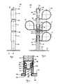
- An example aircraft conduit harness retention system will now be described with reference to the accompanying figures in which:
-
Figure 1 is a front view of a conduit harness retention system in accordance with the present invention, -
Figure 2 is a side section view of the conduit harness retention system offigure 1 along II-II, -
Figure 3 is a close-up view of a part of the conduit harness retention system offigure 1 , -
Figure 4 is a perspective view of the harness retention system offigure 1 , and, -
Figure 5 shows alternative arrangements of the harness retention system offigure 1 . - A conduit
harness retention system 100 is provided which comprises abase 102, afirst spacer 104, asecond spacer 106 and acap 108. The harness retention system retains a first P-clip harness 110, a second P-clip harness 112, a third P-clip harness 114 and a fourth P-clip harness 116 as will be described below. - The
base 102 comprises a firstcylindrical portion 118 which terminates at a first end in acircular flange 120. The flange can be adhered to an aircraft fuselage (or other component) 10. Thebase 102 comprises a secondcylindrical portion 122 at a second end, of a smaller diameter than the firstcylindrical portion 118 to form ashoulder 124. The secondcylindrical portion 122 terminates in a pair of axially extendingflexible fingers 126, each of which comprise a radially outwardly extendingtab 128. - The
first spacer 104 comprises a firstcylindrical portion 130 which, at a first end, defines ablind bore 132 terminating at anend wall 134. The bore extends radially into a first diametrically opposed pair ofslots 136, a second diametrically opposed pair ofslots 138 and a third diametrically opposed pair ofslots 140. - The
first spacer 104 is formed substantially identically to thebase 102 at a second end, defining a secondcylindrical portion 142, a shoulder 144, a pair of axially extendingflexible fingers 146 terminating intabs 148. - The
second spacer 106 is substantially identical to thefirst spacer 104. - The
cap 108 is generally cylindrical and comprises a formation similar to the first end of thefirst spacer 104, having ablind bore 150 terminating in anend wall 152. Thebore 152 only has two pairs of diametricallyopposed slots - Each P-
clip harness loop 158 and aflange 160 projecting tangentially therefrom. Theflange 160 defines abore 162 therethrough. - In use, the
base 102 is attached to theaircraft fuselage 10 by adhesive. The first P-clip harness 110 is passed over thebase 102 such that thebore 162 surrounds the secondcylindrical portion 122 and abuts theshoulder 124. Thefirst spacer 104 is then mated with thebase 102 such that thefingers 126 enter theblind bore 132. Because of thetabs 128, the fingers deform radially inwardly until the tabs snap into thefirst slots 136 at which point thefingers 126 resile outwardly. In order to secure the P-clip harness 110 firmly, thefirst spacer 104 is pushed down further such that thefingers 126 deform inwardly again and thetabs 128 snap into thesecond slots 138. At this point a groove is formed proximate theshoulder 124 equal in width to the width of theflange 160. The first P-clip 110 harness is therefore secure. - The second and third P-
clip harnesses cylindrical portion 142 of thefirst spacer 104. The P-clip harnesses second spacer 106 is then placed over the P-clip harnesses tabs 148 engage the lower slots of thesecond spacer 106 only because the combined thickness of the flanges of the second and third P-clip harnesses - Finally, the fourth P-
clip harness 116 is placed over the upper end of thesecond spacer 106 and the end cap used to secure it in place. - It will be noted that the first and
second spacers third slots 140 are used in the event that no P-clip harness will be inserted between the spacer and the base or spacer below, as shown infigure 5 in which the second P-clip harness 112 is mounted alone. - Variations of the above embodiment may fall within the scope of the present invention.
- For example a further pair of opposing slots may be provided on each spacer as a failsafe position, should the
tabs 148 become dislodged from the lowest pair of slots. - Other types of harnesses or clips may be used; the invention is not limited to P-clip harnesses. The system may be used to retain harnesses suitable for other types of conduits; e.g. fuel, pneumatic, hydraulic or coolant.
- The snap-fit formations may be designed such that they cannot be disassembled without breaking them. This ensures that the components may only be used once.
- The base may be arranged with a snap-fit formation on an upper end thereof to engage the bore of a p-clip without the use of a cap. Such a snap-fit formation preferably comprises radially outwardly biased fingers to hook over the periphery of the p-clip bore.
Claims (12)
- An aircraft conduit harness retention system comprising:a first part having an attachment portion for attachment to an aircraft component at a first end and a first mating formation at a second end,a second part having a second mating formation,wherein the first mating formation and the second mating formation are engageable via a snap-fit to retain a flange of a first conduit harness therebetween such that the conduit harness is offset from the aircraft component.
- An aircraft conduit harness retention system according to claim 1 in which the first part is a base part and the attachment portion is for attachment to an aircraft fuselage.
- An aircraft conduit harness retention system according to claim 1 or 2 in which the second part has a third mating formation defined at an end opposite the second mating formation, the third formation engageable with a further second mating formation of a further mount cap to retain a flange of a conduit harness therebetween.
- An aircraft conduit harness retention system according to any of claims 1 to 3 in which the first mating formation and the second mating formation form a snap-fit connection engageable in a first snap-fit position and a second snap-fit position in the direction of engagement.
- An aircraft conduit harness retention system according to claim 4 in which;
in the first snap-fit position the first mating formation and the second mating formation are engaged to provide a recess of a first width therebetween, and,
in the second snap-fit position the first mating formation and the second mating formation are engaged to provide a recess of a second width therebetween,
wherein the second width is greater than the first width. - An aircraft conduit harness retention system according to claim 5 in which one of the first mating formation and the second mating formation comprises a pair of similar, spaced mating formations each engageable by the other of the first mating formation and the second mating formation.
- An aircraft conduit harness retention system according to claim 4 in which in the first snap-fit position first mating formation and the second mating formation are engaged to provide a recess therebetween, and in the second snap-fit position the first and second mating parts abut.
- An aircraft conduit harness retention system according to any preceding claim in which one of the first and second parts comprises an elongate portion, and the corresponding mating formation defines a tab configured to resile outwardly to engage a recess on the other mating formation.
- An aircraft conduit harness retention system according to claim 8 in which the elongate portion comprises a resilient finger extending therefrom, the tab defined at a first end of the finger.
- An aircraft conduit harness retention system according to claim 8 in which the elongate portion is generally cylindrical, the finger extends axially therefrom, and the tab extends radially therefrom.
- An aircraft conduit harness retention system comprising:a first part having an attachment portion for attachment to an aircraft component at a first end and a first mating formation at a second end,wherein the first mating formation is a snap-fit formation for attachment of a conduit harness.
- An aircraft conduit harness retention system as described herein with reference to, or in accordance with, the accompanying drawings.
Applications Claiming Priority (1)
| Application Number | Priority Date | Filing Date | Title |
|---|---|---|---|
| GBGB1009965.3A GB201009965D0 (en) | 2010-06-15 | 2010-06-15 | Aircraft conduit harness retention system |
Publications (2)
| Publication Number | Publication Date |
|---|---|
| EP2398121A2 true EP2398121A2 (en) | 2011-12-21 |
| EP2398121A3 EP2398121A3 (en) | 2014-04-23 |
Family
ID=42471648
Family Applications (1)
| Application Number | Title | Priority Date | Filing Date |
|---|---|---|---|
| EP11169663.9A Withdrawn EP2398121A3 (en) | 2010-06-15 | 2011-06-13 | Aircraft conduit harness retention system |
Country Status (3)
| Country | Link |
|---|---|
| US (2) | US8888053B2 (en) |
| EP (1) | EP2398121A3 (en) |
| GB (1) | GB201009965D0 (en) |
Cited By (3)
| Publication number | Priority date | Publication date | Assignee | Title |
|---|---|---|---|---|
| EP3396221A1 (en) * | 2017-04-28 | 2018-10-31 | The Boeing Company | Tool-free cable mounting device |
| EP3833897A4 (en) * | 2018-08-06 | 2022-04-27 | Hubbell Incorporated | Combination securing clips |
| NO348521B1 (en) * | 2023-07-30 | 2025-02-24 | Isonova As | System for installing traction pipes in tunnels and rock cavities |
Families Citing this family (32)
| Publication number | Priority date | Publication date | Assignee | Title |
|---|---|---|---|---|
| GB201009965D0 (en) * | 2010-06-15 | 2010-07-21 | Airbus Operations Ltd | Aircraft conduit harness retention system |
| TWI390118B (en) * | 2010-09-08 | 2013-03-21 | Hannstar Display Corp | Fixing mechanism |
| CA2829748C (en) * | 2011-03-10 | 2019-09-10 | Bombardier Inc. | Standoff device and method of installation of harness |
| US9556972B2 (en) * | 2011-07-15 | 2017-01-31 | Commscope Technologies Llc | Adjustable cable manager |
| EP2590283A1 (en) * | 2011-11-03 | 2013-05-08 | CMP Products Limited | A Tie for Fixing an Article to a Surface |
| US9528535B2 (en) * | 2013-03-11 | 2016-12-27 | Illinois Tool Works Inc. | Multifunctional adaptor |
| ES2707730T3 (en) * | 2013-09-13 | 2019-04-04 | Te Connectivity Corp | Adjustable cable managers |
| GB2540881B (en) * | 2016-07-15 | 2017-08-16 | Avestin Ltd | Improvements relating to scaffolding ties |
| WO2018226874A1 (en) * | 2017-06-06 | 2018-12-13 | Hubbell Incorporated | System and method for hanging a cable |
| US10096934B1 (en) * | 2017-09-25 | 2018-10-09 | Amphenol Corporation | Cable support and attachment device |
| US10663089B2 (en) * | 2017-11-03 | 2020-05-26 | Panduit Corp. | Universal cable tie mount |
| US10670169B2 (en) * | 2017-12-12 | 2020-06-02 | Ppc Broadband Fiber Ltd. | Stackable brackets for microducts and cables |
| US10598302B2 (en) * | 2017-12-27 | 2020-03-24 | TorcSill Foundations, LLC | Safety anchor device for high pressure pipe couplings |
| US10663353B2 (en) * | 2018-08-23 | 2020-05-26 | Kidde Technologies, Inc. | Clamp for sensors |
| FR3091960B1 (en) * | 2019-01-22 | 2021-07-16 | Safran Electrical & Power | System for fixing a cable to a structural element |
| USD942256S1 (en) | 2020-08-17 | 2022-02-01 | Innovative Dental Technologies, Inc | Clip |
| US12149061B2 (en) * | 2021-09-15 | 2024-11-19 | Schneider Electric USA, Inc. | Short circuit cable support |
| CN217355883U (en) * | 2022-05-25 | 2022-09-02 | 泛达通讯零部件(无锡)有限公司 | Rotatable fixing seat |
| USD1008004S1 (en) | 2022-06-24 | 2023-12-19 | Hubbell Incorporated | Cable hanger |
| US12249822B2 (en) | 2022-06-24 | 2025-03-11 | Hubbell Incorporated | Electrical cable hangers |
| USD1008006S1 (en) | 2022-06-24 | 2023-12-19 | Hubbell Incorporated | Cable hanger |
| USD1007284S1 (en) | 2022-06-24 | 2023-12-12 | Hubbell Incorporated | Cable hanger |
| USD1008007S1 (en) | 2022-06-24 | 2023-12-19 | Hubbell Incorporated | Cable hanger |
| USD1007286S1 (en) | 2022-06-24 | 2023-12-12 | Hubbell Incorporated | Cable hanger |
| USD1007285S1 (en) | 2022-06-24 | 2023-12-12 | Hubbell Incorporated | Cable hanger |
| USD1061228S1 (en) | 2022-08-22 | 2025-02-11 | Hubbell Incorporated | Electrical component hanger |
| USD1067761S1 (en) | 2022-08-22 | 2025-03-25 | Hubbell Incorporated | Electrical component hanger |
| USD1017388S1 (en) | 2022-10-01 | 2024-03-12 | Hubbell Incorporated | Cable hanger |
| US12275359B2 (en) * | 2023-06-16 | 2025-04-15 | The Boeing Company | One-piece co-molded snap-on apparatus, and support system and method of using the same |
| EP4539279A1 (en) * | 2023-10-13 | 2025-04-16 | Airbus Operations GmbH | Adjustable spacer for holding supply lines |
| EP4583336A1 (en) * | 2024-01-05 | 2025-07-09 | B/E Aerospace, Inc. | Adjustable spacing device |
| US20260035063A1 (en) * | 2024-08-01 | 2026-02-05 | The Boeing Company | Snap-on support assembly and method |
Citations (3)
| Publication number | Priority date | Publication date | Assignee | Title |
|---|---|---|---|---|
| EP0316606A1 (en) * | 1987-11-14 | 1989-05-24 | A. Raymond & Cie | Holder for fixing supply lines in motor vehicles |
| EP2045475A2 (en) * | 2007-10-05 | 2009-04-08 | Panduit Corporation | Stackable mount assembly including indexing/locking features |
| DE102008041230A1 (en) * | 2008-08-13 | 2010-02-25 | Airbus Deutschland Gmbh | Holder for fixing line i.e. electric cable, at position in body cell structure of airplane, has line guide formed for line that is fixable in torsion-free manner, where complete mechanical decoupling is provided between holder and structure |
Family Cites Families (26)
| Publication number | Priority date | Publication date | Assignee | Title |
|---|---|---|---|---|
| US2331098A (en) * | 1942-02-10 | 1943-10-05 | Bendix Aviat Ltd | Tube clamp |
| US2407217A (en) * | 1944-05-08 | 1946-09-10 | Banneyer Joseph | Conduit supporting device |
| GB875935A (en) | 1958-11-27 | 1961-08-23 | Robin & Sons Ltd H | Improvements in or relating to cleats |
| US3563131A (en) * | 1969-04-23 | 1971-02-16 | Lockheed Aircraft Corp | Spacer |
| US3552696A (en) * | 1969-05-29 | 1971-01-05 | Emil H Orenick | Cable retainer |
| US4145977A (en) * | 1978-02-02 | 1979-03-27 | Bernard Industries Co. | Modular shelf system with assembly-disassembly feature |
| US4618114A (en) * | 1982-09-29 | 1986-10-21 | Lof Plastics Inc. | Conduit spacer and support |
| US4601447A (en) * | 1984-10-29 | 1986-07-22 | Lof Plastics Inc. | Conduit spacer anchoring system |
| JPH0334488Y2 (en) * | 1985-09-19 | 1991-07-22 | ||
| FR2589510B1 (en) * | 1985-10-30 | 1987-12-18 | Neiman Sa | BAYONET MOUNT LOCK |
| FR2631396B1 (en) * | 1988-05-11 | 1991-01-04 | Marot Jacques | ASSEMBLY DEVICE FOR REMOVABLE OR MODULAR ELEMENTS |
| US4962573A (en) * | 1989-10-17 | 1990-10-16 | Geerpres, Inc. | Clasp for retaining containers |
| US5271588A (en) * | 1992-07-17 | 1993-12-21 | General Electric Company | Multi-piece tube clamp |
| US5612509A (en) * | 1994-04-29 | 1997-03-18 | Market; Roger | Stackable wire staple and raceway system |
| US5564672A (en) | 1994-06-06 | 1996-10-15 | Matson; Bradley A. | Conduit binding system for use in restricted spaces |
| DE19820651B4 (en) * | 1998-05-08 | 2007-04-12 | Kabelschlepp Gmbh | Cable guide assembly with a zugentlastenden attachment of at least one guided in the wiring guide line |
| US6899305B2 (en) * | 1999-01-12 | 2005-05-31 | Andrew Corporation | Stackable transmission line hanger |
| US6443403B1 (en) * | 2000-09-11 | 2002-09-03 | Panduit Corp. | Cable routing clamp and method of application |
| US6663054B2 (en) * | 2001-10-26 | 2003-12-16 | Fci | Combined safety clip and closure for a conductor support |
| US7090174B2 (en) * | 2001-11-09 | 2006-08-15 | Andrew Corporation | Anchor rail adapter and hanger and method |
| US7686259B2 (en) * | 2003-02-21 | 2010-03-30 | Panduit Corp. | Ringpost assembly |
| US7726922B2 (en) * | 2003-12-09 | 2010-06-01 | The Boeing Company | Quick release support post and associated method |
| TWM292022U (en) * | 2006-01-10 | 2006-06-11 | Shiang-Chiuan Hung | Improved assembly structure of annular-sectioned-type hollow pipe for rack |
| US7478783B2 (en) * | 2006-06-05 | 2009-01-20 | Deere & Company | Frame mounted hose clamp |
| GB201009965D0 (en) * | 2010-06-15 | 2010-07-21 | Airbus Operations Ltd | Aircraft conduit harness retention system |
| GB201009967D0 (en) * | 2010-06-15 | 2010-07-21 | Airbus Operations Ltd | Conduit harness |
-
2010
- 2010-06-15 GB GBGB1009965.3A patent/GB201009965D0/en not_active Ceased
-
2011
- 2011-06-13 EP EP11169663.9A patent/EP2398121A3/en not_active Withdrawn
- 2011-06-14 US US13/159,530 patent/US8888053B2/en not_active Expired - Fee Related
-
2014
- 2014-10-17 US US14/517,198 patent/US9168997B2/en not_active Expired - Fee Related
Patent Citations (3)
| Publication number | Priority date | Publication date | Assignee | Title |
|---|---|---|---|---|
| EP0316606A1 (en) * | 1987-11-14 | 1989-05-24 | A. Raymond & Cie | Holder for fixing supply lines in motor vehicles |
| EP2045475A2 (en) * | 2007-10-05 | 2009-04-08 | Panduit Corporation | Stackable mount assembly including indexing/locking features |
| DE102008041230A1 (en) * | 2008-08-13 | 2010-02-25 | Airbus Deutschland Gmbh | Holder for fixing line i.e. electric cable, at position in body cell structure of airplane, has line guide formed for line that is fixable in torsion-free manner, where complete mechanical decoupling is provided between holder and structure |
Cited By (5)
| Publication number | Priority date | Publication date | Assignee | Title |
|---|---|---|---|---|
| EP3396221A1 (en) * | 2017-04-28 | 2018-10-31 | The Boeing Company | Tool-free cable mounting device |
| CN108808595A (en) * | 2017-04-28 | 2018-11-13 | 波音公司 | Tool-free cable mounting device |
| CN108808595B (en) * | 2017-04-28 | 2020-11-20 | 波音公司 | Tool-free cable installation device |
| EP3833897A4 (en) * | 2018-08-06 | 2022-04-27 | Hubbell Incorporated | Combination securing clips |
| NO348521B1 (en) * | 2023-07-30 | 2025-02-24 | Isonova As | System for installing traction pipes in tunnels and rock cavities |
Also Published As
| Publication number | Publication date |
|---|---|
| US20110303799A1 (en) | 2011-12-15 |
| US8888053B2 (en) | 2014-11-18 |
| US9168997B2 (en) | 2015-10-27 |
| US20150060612A1 (en) | 2015-03-05 |
| GB201009965D0 (en) | 2010-07-21 |
| EP2398121A3 (en) | 2014-04-23 |
Similar Documents
| Publication | Publication Date | Title |
|---|---|---|
| US8888053B2 (en) | Aircraft conduit harness retention system | |
| EP2397736A1 (en) | Modular conduit retention system | |
| EP2398122A2 (en) | Conduit harness holder | |
| EP3300197B1 (en) | Self-indexing nut plate | |
| US9853434B2 (en) | Hanger for mounting multiple cables | |
| EP3549215B1 (en) | Suspension assembly | |
| EP2153100B1 (en) | Grommet | |
| CN112838535A (en) | Adapter for mounting cable hangers | |
| US20130187014A1 (en) | Self-Indexing Nut Plate | |
| US7222394B2 (en) | Bushing for metal studs and the like | |
| EP3369149B1 (en) | Hanger for mounting cables | |
| CN107524683B (en) | Fastening system | |
| US11274772B2 (en) | Cable clips | |
| CN104143796A (en) | Cable fixing clip for preventing reverse-assembly | |
| EP3405063B1 (en) | A fastening device and a fastening system | |
| US2419317A (en) | Spring clip for securing conduits, wiring, and the like to structural parts | |
| WO2016062993A1 (en) | Improvements in or relating to connecting devices | |
| US20080169387A1 (en) | Retainer harness clip apparatus | |
| CN105697874A (en) | Grommet | |
| KR20160000451U (en) | The connector of electric cable pipe | |
| EP3194797B1 (en) | Securing device | |
| EP3397845B1 (en) | Heat shield with retention feature | |
| KR200391767Y1 (en) | structure of coupling a clip and a band cable | |
| EP1223650B1 (en) | Pressure plug for supporting electric cables | |
| JP2016066514A (en) | Ground terminal unit |
Legal Events
| Date | Code | Title | Description |
|---|---|---|---|
| AK | Designated contracting states |
Kind code of ref document: A2 Designated state(s): AL AT BE BG CH CY CZ DE DK EE ES FI FR GB GR HR HU IE IS IT LI LT LU LV MC MK MT NL NO PL PT RO RS SE SI SK SM TR |
|
| AX | Request for extension of the european patent |
Extension state: BA ME |
|
| PUAI | Public reference made under article 153(3) epc to a published international application that has entered the european phase |
Free format text: ORIGINAL CODE: 0009012 |
|
| PUAL | Search report despatched |
Free format text: ORIGINAL CODE: 0009013 |
|
| AK | Designated contracting states |
Kind code of ref document: A3 Designated state(s): AL AT BE BG CH CY CZ DE DK EE ES FI FR GB GR HR HU IE IS IT LI LT LU LV MC MK MT NL NO PL PT RO RS SE SI SK SM TR |
|
| AX | Request for extension of the european patent |
Extension state: BA ME |
|
| RIC1 | Information provided on ipc code assigned before grant |
Ipc: H02G 3/32 20060101AFI20140314BHEP Ipc: F16L 3/00 20060101ALI20140314BHEP |
|
| 17P | Request for examination filed |
Effective date: 20141020 |
|
| RBV | Designated contracting states (corrected) |
Designated state(s): AL AT BE BG CH CY CZ DE DK EE ES FI FR GB GR HR HU IE IS IT LI LT LU LV MC MK MT NL NO PL PT RO RS SE SI SK SM TR |
|
| 17Q | First examination report despatched |
Effective date: 20141222 |
|
| GRAP | Despatch of communication of intention to grant a patent |
Free format text: ORIGINAL CODE: EPIDOSNIGR1 |
|
| INTG | Intention to grant announced |
Effective date: 20161104 |
|
| STAA | Information on the status of an ep patent application or granted ep patent |
Free format text: STATUS: THE APPLICATION IS DEEMED TO BE WITHDRAWN |
|
| 18D | Application deemed to be withdrawn |
Effective date: 20170315 |