EP2398109A1 - Heat exchanger and method for operating and manufacturing same - Google Patents
Heat exchanger and method for operating and manufacturing same Download PDFInfo
- Publication number
- EP2398109A1 EP2398109A1 EP20110170132 EP11170132A EP2398109A1 EP 2398109 A1 EP2398109 A1 EP 2398109A1 EP 20110170132 EP20110170132 EP 20110170132 EP 11170132 A EP11170132 A EP 11170132A EP 2398109 A1 EP2398109 A1 EP 2398109A1
- Authority
- EP
- European Patent Office
- Prior art keywords
- opening
- heat exchanger
- energy storage
- profile
- housing surface
- Prior art date
- Legal status (The legal status is an assumption and is not a legal conclusion. Google has not performed a legal analysis and makes no representation as to the accuracy of the status listed.)
- Withdrawn
Links
Images


Classifications
-
- F—MECHANICAL ENGINEERING; LIGHTING; HEATING; WEAPONS; BLASTING
- F28—HEAT EXCHANGE IN GENERAL
- F28F—DETAILS OF HEAT-EXCHANGE AND HEAT-TRANSFER APPARATUS, OF GENERAL APPLICATION
- F28F3/00—Plate-like or laminated elements; Assemblies of plate-like or laminated elements
- F28F3/12—Elements constructed in the shape of a hollow panel, e.g. with channels
-
- F—MECHANICAL ENGINEERING; LIGHTING; HEATING; WEAPONS; BLASTING
- F28—HEAT EXCHANGE IN GENERAL
- F28F—DETAILS OF HEAT-EXCHANGE AND HEAT-TRANSFER APPARATUS, OF GENERAL APPLICATION
- F28F21/00—Constructions of heat-exchange apparatus characterised by the selection of particular materials
- F28F21/06—Constructions of heat-exchange apparatus characterised by the selection of particular materials of plastics material
- F28F21/065—Constructions of heat-exchange apparatus characterised by the selection of particular materials of plastics material the heat-exchange apparatus employing plate-like or laminated conduits
-
- H—ELECTRICITY
- H01—ELECTRIC ELEMENTS
- H01M—PROCESSES OR MEANS, e.g. BATTERIES, FOR THE DIRECT CONVERSION OF CHEMICAL ENERGY INTO ELECTRICAL ENERGY
- H01M10/00—Secondary cells; Manufacture thereof
- H01M10/60—Heating or cooling; Temperature control
- H01M10/61—Types of temperature control
- H01M10/613—Cooling or keeping cold
-
- H—ELECTRICITY
- H01—ELECTRIC ELEMENTS
- H01M—PROCESSES OR MEANS, e.g. BATTERIES, FOR THE DIRECT CONVERSION OF CHEMICAL ENERGY INTO ELECTRICAL ENERGY
- H01M10/00—Secondary cells; Manufacture thereof
- H01M10/60—Heating or cooling; Temperature control
- H01M10/64—Heating or cooling; Temperature control characterised by the shape of the cells
- H01M10/643—Cylindrical cells
-
- H—ELECTRICITY
- H01—ELECTRIC ELEMENTS
- H01M—PROCESSES OR MEANS, e.g. BATTERIES, FOR THE DIRECT CONVERSION OF CHEMICAL ENERGY INTO ELECTRICAL ENERGY
- H01M10/00—Secondary cells; Manufacture thereof
- H01M10/60—Heating or cooling; Temperature control
- H01M10/64—Heating or cooling; Temperature control characterised by the shape of the cells
- H01M10/647—Prismatic or flat cells, e.g. pouch cells
-
- H—ELECTRICITY
- H01—ELECTRIC ELEMENTS
- H01M—PROCESSES OR MEANS, e.g. BATTERIES, FOR THE DIRECT CONVERSION OF CHEMICAL ENERGY INTO ELECTRICAL ENERGY
- H01M10/00—Secondary cells; Manufacture thereof
- H01M10/60—Heating or cooling; Temperature control
- H01M10/65—Means for temperature control structurally associated with the cells
- H01M10/655—Solid structures for heat exchange or heat conduction
- H01M10/6554—Rods or plates
-
- H—ELECTRICITY
- H01—ELECTRIC ELEMENTS
- H01M—PROCESSES OR MEANS, e.g. BATTERIES, FOR THE DIRECT CONVERSION OF CHEMICAL ENERGY INTO ELECTRICAL ENERGY
- H01M10/00—Secondary cells; Manufacture thereof
- H01M10/60—Heating or cooling; Temperature control
- H01M10/65—Means for temperature control structurally associated with the cells
- H01M10/655—Solid structures for heat exchange or heat conduction
- H01M10/6556—Solid parts with flow channel passages or pipes for heat exchange
-
- F—MECHANICAL ENGINEERING; LIGHTING; HEATING; WEAPONS; BLASTING
- F28—HEAT EXCHANGE IN GENERAL
- F28F—DETAILS OF HEAT-EXCHANGE AND HEAT-TRANSFER APPARATUS, OF GENERAL APPLICATION
- F28F3/00—Plate-like or laminated elements; Assemblies of plate-like or laminated elements
- F28F3/08—Elements constructed for building-up into stacks, e.g. capable of being taken apart for cleaning
- F28F3/086—Elements constructed for building-up into stacks, e.g. capable of being taken apart for cleaning having one or more openings therein forming tubular heat-exchange passages
-
- H—ELECTRICITY
- H01—ELECTRIC ELEMENTS
- H01M—PROCESSES OR MEANS, e.g. BATTERIES, FOR THE DIRECT CONVERSION OF CHEMICAL ENERGY INTO ELECTRICAL ENERGY
- H01M10/00—Secondary cells; Manufacture thereof
- H01M10/60—Heating or cooling; Temperature control
- H01M10/62—Heating or cooling; Temperature control specially adapted for specific applications
- H01M10/625—Vehicles
-
- Y—GENERAL TAGGING OF NEW TECHNOLOGICAL DEVELOPMENTS; GENERAL TAGGING OF CROSS-SECTIONAL TECHNOLOGIES SPANNING OVER SEVERAL SECTIONS OF THE IPC; TECHNICAL SUBJECTS COVERED BY FORMER USPC CROSS-REFERENCE ART COLLECTIONS [XRACs] AND DIGESTS
- Y02—TECHNOLOGIES OR APPLICATIONS FOR MITIGATION OR ADAPTATION AGAINST CLIMATE CHANGE
- Y02E—REDUCTION OF GREENHOUSE GAS [GHG] EMISSIONS, RELATED TO ENERGY GENERATION, TRANSMISSION OR DISTRIBUTION
- Y02E60/00—Enabling technologies; Technologies with a potential or indirect contribution to GHG emissions mitigation
- Y02E60/10—Energy storage using batteries
Definitions
- the present invention relates to a heat exchanger and to a method for producing a heat exchanger, which can be used, for example, for cooling energy storage cells.
- the cells can be pushed into fixed insertion pockets between the coolant-filled "spikes" of the cooling gel and fixed.
- Thedeigel is very massive and therefore very heavy. Furthermore, the pockets have a slight excess for reasons of process reliability. Due to this necessary tolerance, the heat transfer based on thermal contact deteriorates significantly.
- the cells can be placed on a traversed with coolant channels cooling plate and fixed separately.
- the cells are cooled only at the bottom of the hard case.
- This one-sided cooling leads to high temperature differences within the cell.
- the embodiments of the cooling plate with and without cooling plates are heavy due to the high weight of the cooling plate and require additional fastening and bracing elements. A weight reduction by omitting the bracing elements would lead to a significantly reduced heat transfer and thus reduce the effectiveness of the cooling.
- cooling plate with cooling plates thin-walled L or T-profiles are clamped on a traversed with coolant channels cooling plate, which transport the cooling capacity of the cooling plate to the cells, which are in the "sandwich" of the cooling plates. It can be significantly reduced by an optimized design of the cooling plates, the temperature difference in the cell compared to the embodiment without a cooling plate. However, the weight increases significantly due to the cooling plates and the increased effort for fixing and clamping of metal sheets and cells. Also, two thermal contact-based interfaces are needed for this solution. In thedeigel and the embodiment without cooling plate only one is needed. Thermal contacts always place increased demands on tolerance, surface quality and rigidity in order to ensure a good thermal transition coefficient.
- the present invention is based on the finding that curved shaft profiles are suitable for thermally connecting energy cells with a heat exchanger.
- a slide-in cooler based on curved manhole profiles can be created.
- the slide-in cooler is suitable as a cooler for cooling energy storage systems.
- the energy storage cells are plugged into the cooler.
- the shaft profiles press against the cells and thus form a heat transfer to the cell.
- the result is a simple and lightweight design for the cooling components of cells while ensuring effective and safe cooling.
- the construction either contains all the functions relating to connection and clamping of the cooling component and cells directly, or at least allows simple solutions.
- the construction according to the invention is very compact and enables effective cooling of prismatic cells with metal housing.
- the good efficiency is achieved by the fact that the only thermal interface between shaft profile and cell housing by the constraint of the elastically deformed shaft profile has a very good heat transfer.
- the position of the cooling via the cell height can be set variably or even supplemented by an additional bottom cooling of the cells.
- Another advantage is the closed solution, as it is just a product that can be mounted without any special parts or tools in any environment. Access to the cells is not hampered by the modular design. Single cells can be easily exchanged.
- the heat exchanger according to the invention can be used for small-sized energy storage, for example based on lithium ions.
- the amount of heat continuously generated due to the power loss during charging or discharging inside the cell, which corresponds to the power loss of the cell, can be dissipated via the shaft profiles with the same speed. It can be ensured that the temperature difference within a cell and within a module does not exceed a cell-specific value.
- the approach of the present invention provides an optimized method for cooling "hard" cell cells, typically prismatic or cylindrical cells with aluminum housings.
- the present invention provides a heat exchanger for cooling at least one energy storage cell, having the following features: a first housing surface having at least one first opening; a second housing surface having at least a second opening, wherein the second housing surface of the first housing surface and the second opening of the first opening is arranged opposite; and at least one well profile connected to a peripheral edge region of the first opening and having a peripheral edge region of the second opening and extending between the first and the second housing surface to form a wall of a storage slot for an energy storage cell, the well profile in a between the first and the second housing surface lying region has an elastic curvature in the direction of an interior of the receiving shaft.
- the energy storage cell may be a galvanic element.
- the energy storage cell can be used for example in an electric vehicle or a hybrid vehicle.
- the heat exchanger has a housing, in which the first housing surface and the second housing surface are arranged opposite one another.
- the housing has one or a plurality of receiving wells which form through holes through the housing.
- Each of the receiving wells is formed by a first opening, a second opening and a manhole profile.
- the receiving wells form pillars between the first and second housing surfaces.
- the shaft profile may be made of a different material than the housing surfaces and have been subsequently connected to this. For this purpose, the shaft profile may have been connected to the openings, for example, in each case by means of a cohesive or a positive connection technology.
- the openings may be adapted in their cross-sectional area to a cross-sectional area of the energy source to be absorbed.
- the openings may have a round cross section or a rectangular cross section.
- a cross-sectional area of the manhole profile can be adapted to the cross-sectional area of the openings.
- Each of the receiving wells is configured to receive one or more energy storage cells.
- the energy storage cell can be introduced into the receiving shaft and shoot down flush with the first housing surface and the second housing surface or protrude beyond the first, the second or both housing surfaces.
- the housing may have further housing surfaces, which adjoin the first housing surface and the second housing surface to close the housing to the outside.
- the elastic curvature can extend over a partial area or over an entire length of the manhole profile.
- an energy storage cell If an energy storage cell is arranged in a receiving shaft, it presses with its side surface against the elastic curvature and deforms it. The deformation of the elastic curvature produces a restoring force with which the elastic curvature presses against the side surface of the energy storage cell. As a result, the energy storage cell is mechanically fixed in the receiving shaft. In addition, a contact surface is formed between the elastic curvature and the side surface of the energy storage cell, via which there is a thermally conductive connection between the heat exchanger and the energy storage cell.
- an inner diameter of the receiving shaft in the region of the elastic curvature can be smaller than a corresponding outer diameter of the energy storage cell.
- the elastic curvature can exert a holding force on the energy storage cell and form a thermal connection to the energy storage cell when the energy storage cell is arranged in the receiving shaft.
- the corresponding outer diameter is an outer diameter of the energy storage cell in the region opposite to the elastic curvature when the energy storage cell is arranged in the receiving well.
- the area where the inside diameter of the receiving shaft is smaller than the corresponding outer diameter of the energy storage cell for example, may extend over a third, half or two-thirds of the length of the receiving shaft. This area can be arranged centrally with respect to the length of the receiving shaft.
- the at least one shaft profile can be bent continuously in the region lying between the first and the second housing surface in order to form the elastic curvature.
- the elastic curvature can be generated by a deformation of the manhole profile, which results from the rigid connection of the manhole profile with the openings.
- the shaft profile may be bent before the connection with the openings.
- the at least one shaft profile is connected to the peripheral edge regions of the at least one first opening and the at least one second opening in a continuous and fluid-tight manner. This makes it possible that a gap between the housing surfaces is flowed through by a fluid. As a result, the heat dissipation via the shaft profiles can be increased.
- the heat exchanger may have a first fluid port for supplying a fluid and a second fluid port for discharging the fluid.
- the fluid connections can be arranged so that the fluid can flow around the wall of the at least one receiving shaft in a region between the first and the second housing surface.
- the heat exchanger can be connected to a cooling circuit.
- the housing surfaces may be made of plastic and the at least one shaft profile may be made of metal.
- the plastic can save weight.
- the metal offers a high thermal conductivity.
- the at least one shaft profile may be a tube. Depending on the cross-sectional area of the energy source, this may be a round tube or a flat tube.
- the at least one shaft profile can be composed of several separate profile sections.
- the heat exchanger can have a number of first openings, a number of second openings corresponding to the number of first openings and a number of shaft profiles corresponding to the number of first openings, around a number of receiving shafts corresponding to the number of first openings for a number of energy storage cells corresponding to the number of first openings to build.
- the receiving wells may be evenly distributed over the housing surfaces, for example, the receiving wells may be arranged in a plurality of rows and a plurality of columns, wherein adjacent receiving wells may be arranged offset from one another. A distance between two adjacent receiving wells can be chosen so that on the one hand optimal heat dissipation is ensured and on the other hand the largest possible number of energy storage cells can be arranged on the smallest possible area.
- the heat exchanger according to the invention may comprise the at least one energy storage cell.
- the energy storage cell can be arranged in the receiving shaft and held in position by the elastic curvature. Thus, a complete energy storage system is created.
- the energy storage cell may include a bracket extending along opposite side surfaces of the effusion memory cell. Thus, a part of the bracket between the side surfaces of the energy storage cell and the wall of the receiving shaft can be located.
- the clip may allow additional fixation of the energy storage cell in the receiving shaft.
- the clip may for example have hooks.
- the present invention further provides a method for producing a heat exchanger for cooling at least one energy storage cell, which the comprising the steps of: providing a housing having a first housing surface having at least a first opening and a second housing surface having at least a second opening wöbei the second housing surface of the first housing surface, and the second opening of the first opening opposite one another; Inserting a well profile into the at least one first and at least one second opening so that the well profile extends between the first and second casing surfaces to form a wall of a receptacle for an energy storage cell, wherein a diameter of each of the first and second openings is larger is an outer diameter of the well profile such that a peripheral edge region of the first opening and a peripheral edge region of the second opening is at least partially spaced from the well profile; and continuous connection of the manhole profile with the peripheral edge region of the first opening and the peripheral edge region of the second opening, so that the manhole profile has an elastic curvature in the direction of an interior of the receiving shaft in a region lying between the first and
- the elastic curvature can be generated by connecting the manhole profile with the housing surfaces, so that no pre-bending for the manhole profile is required.
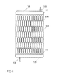
- Fig. 1 shows a representation of a heat exchanger according to the invention from above, according to an embodiment of the present invention.
- the Heat exchanger has a housing from which in the in Fig. 1 shown a first housing surface 102 is shown.
- the first housing surface 102 has a plurality of first openings 104, of which only one opening is provided with a reference numeral 104 for the sake of clarity.
- Each of the first openings 104 is each part of a receiving slot for receiving an energy storage cell.
- the first openings 104 have a rectangular cross-sectional area.
- the first openings 104 are arranged in a plurality of columns and in a plurality of rows.
- the first openings 104 are arranged in seven columns, which each have 12 and 13 openings 104 alternately.
- the first openings 104 are offset relative to one another with respect to adjacent columns.
- the heat exchanger has two collectors 108 arranged at opposite ends of the heat exchanger.
- the collectors 106 form containers which each have a fluid connection 108.
- Fig. 2 shows a front view of the in Fig. 1 shown heat exchanger. Shown are an arrangement of the first housing surface 102 and an opposite second housing surface 202. The first housing surface 102 and the second housing surface 202 are arranged parallel and spaced from one another. In each case an energy storage cell 220 is arranged in the receiving shafts of the heat exchanger, of which only one is provided with a reference numeral 220 for the sake of clarity. According to this embodiment, the energy storage cells 220 protrude beyond the first housing surface 102 and the second housing surface 202, respectively.
- the heat exchanger is arranged approximately centrally with respect to a height of the energy storage cells 220.
- Fig. 3 shows a side view of the in Fig. 1
- an energy storage cell 220 is arranged, of which only one is provided with a reference numeral for the sake of clarity.
- the energy storage cells 220 protrude beyond the first housing surface 102 and the second housing surface 202, respectively.
- the heat exchanger is arranged approximately centrally with respect to a height of the energy storage cells 220.
- a section 330 is in Fig. 4 shown enlarged
- Fig. 4 shows the cutout 330 Fig. 3 , Shown is a side view of the heat exchanger with an energy storage cell 220.
- the energy storage cell 220 is disposed in a receiving shaft of the heat exchanger.
- the receiving shaft is formed by two opposing openings or passages in the first housing surface 102 and the second housing surface 202.
- the passages may correspond to the wall of the housing surfaces 102, 202 in the region of the openings.
- the openings of the housing surfaces 102, 202 are connected via a shaft profile 435.
- the edge regions of the housing surfaces 102, 202 are bent outward.
- the shaft profile 435 is connected to the housing surfaces 102, 202 at the edge regions.
- the shaft profile 435 has a bulge into the interior of the shaft profile 435.
- the manhole profile 435 has a larger cross-sectional area at the edge regions than therebetween.
- the smallest cross-sectional area has the well profile 435 approximately midway between the first and second housing surfaces 102, 202.
- the energy storage cell 220 points along the in Fig. 4 shown narrow side to a larger diameter than the shaft profile 435 in the region of the smallest cross-sectional area.
- the cell 220 has an oversize.
- a thermal contact under pressure arises between the side surfaces of the cell 220 and the well profile 435.
- the energy storage cell 220 has brackets 437 or the like.
- Fig. 5 shows the cutout 330 Fig. 3 in a front view. Shown is a section of the heat exchanger with an energy storage cell 220.
- the energy storage cell 220 is arranged in a receiving shaft of the heat exchanger.
- the receiving shaft is like in Fig. 4 described trained.
- the cell 220 points along the in Fig. 5 shown broad side on a smaller cross section than the shaft profile at its narrowest point. Thus, the cell 220 is undersized.
- brackets or snap hooks are provided.
- a clip 437 is attached to an upper side of the energy storage cell 220 and extends along the energy storage cell 220 on both sides.
- the clip 437 has outwardly bent hooks at end sections, which hook onto the edge regions of the opening in the second housing surface 202.
- Fig. 6 shows a cross-sectional view of the housing (cooler can) of in Fig. 1 shown with the first and second housing surface 102, 202.
- the housing may for example consist of plastic.
- Fig. 7 shows a cross-sectional view of a distributor 110 (header) of the in Fig. 1 shown heat exchanger.
- the distributor 110 has a plurality of openings, the cross-section of which increases the farther they are from the inlet opening of the fluid.
- the distributor 110 may be made of plastic, for example.
- Fig. 8 shows one of a collector 106 (tank) of a erfindungsgerna built heat exchanger with the inlet opening 108 for the fluid.
- Fig. 9 shows the cutout 330 Fig. 3 without energy storage cell. Shown is a side view of a receiving shaft of the heat exchanger.
- the receiving shaft is formed by two opposite openings or passages in the first housing surface 102 and the second housing surface 202, which are connected via a shaft profile 435, the shaft profile 435 (cell slot chamber profile) may for example consist of aluminum.
- a section 940 is in Fig. 12 shown enlarged
- Fig. 10 shows the cutout 330 Fig. 3 Shown is a width a of the housing of the cell 220 and a minimum width az of the receiving shaft.
- An overlap z may vary over a circumference of the absorptive shaft, for example, between the front view and the side view.
- the receiving shaft may have at its narrowest point, for example, a smaller diameter than the narrow side, however, a larger diameter than the broad side of the energy storage cell
- Fig. 11 shows the cutout 330 Fig. 3 in a front view, without an energy storage cell.
- a cooler housing formed by the housing surfaces 102, 202 may be made of plastic, for example.
- Fig. 12 shows an enlarged view of the in the Figures 9 and 11 Shown is the first housing surface 102 of the cooler housing, which may for example consist of plastic, and the shaft profile 435.
- the shaft profile 435 may be designed as a tube, for example made of aluminum.
- crimping 1253 creates a fluid-tight connection.
- the fluid-tight connection can be made in addition to folding, for example, by soldering, welding or other joining techniques.
- the fluid-tight connection can be created by positive or non-positive connection or by a thermal or chemical joining process.
- the heat exchanger according to an embodiment of the invention will be described in detail.
- the shaft profiles 435 which are in direct contact with the cells 220.
- the shaft profiles 435 can be, for example, thin-walled tubes in a flat or round design. These are pushed through a cooler housing 102, 202 made of plastic into openings provided for this purpose. The edges of these openings have on both sides of a passage embossment 1253. In addition, the openings are at least partially slightly larger than the outer dimensions of the shaft profiles.
- connection techniques such as gluing, crimping, flanging, soldering, welding, etc. with the passage of the opening.
- the shaft cross section in the middle of the radiator remains virtually unchanged.
- the shaft profile 435 is elastically arched over the thickness of the radiator and know at least one bottleneck in the middle of the radiator.
- the clear dimension of this constriction is slightly smaller than the outer dimension of the cell 220, so that upon insertion of the cell 220 through this opening, the shaft profile 435 is pressed against the rigid cell housing and thus ensures good heat transfer.
- the number of cell bays necessary for battery performance are, for example, in a staggered matrix arrangement. As a result of the matrix offset, sufficient mixing of the cooling fluid in the direction of flow can thus be ensured.
- a plastic tank 106 including bottom 110 both made of plastic, for example, by suitable methods, such as vibration welding, permanently and tightly connected to the radiator housing.
- the Flow through the radiator can be optimized by distributing the openings in the floor 110.
- the fixation of the cooler can be done via jaws on the long sides of the radiator.
- the position of the cells 220 within the radiator is fixed by means of brackets 437.
- these additional brackets can be dispensed with if a profiled bottom is provided in the gravitational direction, whose troughs receive the bottoms of the cells 220 accordingly. This prevents jamming of the cells 220 in the cooler.
- the jumping out of the cells 220 from the cooler is also sufficiently hindered by the clamping action in the cell module.
- connection between the shaft profile and the radiator housing is to be regarded as critical.
- the connection When crimping, high plastic deformation occurs in the shaft profile, which can lead to failure of the material during assembly or operation. Nevertheless, the connection must be permanently tight. A failure of the connection is therefore absolutely excluded.
- the shape of the shaft profile 435 can be optimized, especially on the narrow sides.
- additional layers are introduced, e.g. of heat conducting foils, between the shaft profile 435 and the cell housing to optimize the heat flow.
- the introduction of the curvature in the shaft profile 435 can not be done by elastic deformation during the assembly process but by production of controlled plastically deformed semi-finished products.
Landscapes
- Engineering & Computer Science (AREA)
- Manufacturing & Machinery (AREA)
- Chemical & Material Sciences (AREA)
- Chemical Kinetics & Catalysis (AREA)
- Electrochemistry (AREA)
- General Chemical & Material Sciences (AREA)
- Physics & Mathematics (AREA)
- Thermal Sciences (AREA)
- Mechanical Engineering (AREA)
- General Engineering & Computer Science (AREA)
- Heat-Exchange Devices With Radiators And Conduit Assemblies (AREA)
- Secondary Cells (AREA)
Abstract
Description
Die vorliegende Erfindung bezieht sich auf einen Wärmetauscher und auf ein Verfahren zum Herstellen eines Wärmetauschers, der beispielsweise zur Kühlung von Energiespeicherzellen eingesetzt werden kann.The present invention relates to a heat exchanger and to a method for producing a heat exchanger, which can be used, for example, for cooling energy storage cells.
Bei der effektiven Nutzung kleinformatiger Energiespeicher, beispielsweise auf Lithium-Ionen Basis, im Folgenden auch mit Zelle bezeichnet, besteht das Problem, dass zur Aufrechterhaltung der maximalen Lebensdauer die Zelle innerhalb eines Temperaturfensters betrieben werden muss. Bisherige Lösungen für Energiespeicher basieren auf einem massiven, kühlmitteldurchfluteten Bauteil mit entsprechender Kälteleistung. Die Kühlung der Zellen ist damit durch einen Kühligel oder eine Kühlplatte mit oder ohne Kühlblechen möglich.In the effective use of small-sized energy storage, for example, lithium-ion based, also referred to as cell below, there is the problem that to maintain the maximum life, the cell must be operated within a temperature window. Previous solutions for energy storage based on a massive, coolant-flooded component with appropriate cooling capacity. The cooling of the cells is thus possible by a Kühligel or a cooling plate with or without cooling plates.
Bei dem Kühligel können die Zellen in vorgesehene Einschub-Taschen zwischen den kühlmitteldurchfluteten "Stacheln" des Kühligels eingeschoben und fixiert werden. Der Kühligel ist sehr massiv und damit sehr schwer. Weiterhin haben die Einschubtaschen ein geringes Übermaß aus Gründen der Prozesssicherheit. Aufgrund dieser notwendigen Toleranz verschlechtert sich der auf thermischen Kontakt basierte Wärmeübergang deutlich.In the case of the cooling gel, the cells can be pushed into fixed insertion pockets between the coolant-filled "spikes" of the cooling gel and fixed. The Kühligel is very massive and therefore very heavy. Furthermore, the pockets have a slight excess for reasons of process reliability. Due to this necessary tolerance, the heat transfer based on thermal contact deteriorates significantly.
Bei der Kühlplatte, ohne Kühlbleche können die Zellen auf eine mit Kühlmittelkanälen durchzogene Kühlplatte aufgestellt und gesondert fixiert werden. Dabei werden die Zellen nur am Boden des Hard-Case gekühlt. Diese einseitige Kühlung führt zu hohen Temperaturunterschieden innerhalb der Zelle. Die Ausführungsformen der Kühlplatte mit und ohne Kühlbleche sind aufgrund des hohen Gewichts der Kühlplatte schwer und benötigen zusätzliche Befestigungs- und Verspann-Elemente. Eine Gewichtreduzierung durch Weglassen der Verspann-Elemente würde zu einem deutlich reduzierten Wärmeübergang führen und so die Effektivität der Kühlung herabsetzen.In the cooling plate, without cooling plates, the cells can be placed on a traversed with coolant channels cooling plate and fixed separately. The cells are cooled only at the bottom of the hard case. This one-sided cooling leads to high temperature differences within the cell. The embodiments of the cooling plate with and without cooling plates are heavy due to the high weight of the cooling plate and require additional fastening and bracing elements. A weight reduction by omitting the bracing elements would lead to a significantly reduced heat transfer and thus reduce the effectiveness of the cooling.
Bei der Kühlplatte mit Kühlblechen werden auf eine mit Kühlmittelkanälen durchzogene Kühlplatte dünnwandige L- bzw. T-Profile aufgespannt, welche die Kälteleistung von der Kühlplatte zu den Zellen transportieren, die sich im "Sandwich" der Kühlbleche befinden. Dabei kann durch eine optimierte Gestaltung der Kühlbleche der Temperaturunterschied in der Zelle im Vergleich zu der Ausführungsform ohne Kühlplatte deutlich reduziert werden. Allerdings erhöht sich durch die Kühlbleche und den erhöhten Aufwand für die Fixierung und Verspannung von Blechen und Zellen auch das Gewicht deutlich. Auch werden für diese Lösung zwei thermische kontaktbasierte Schnittstellen benötigt. Bei dem Kühligel und der Ausführungsform ohne Kühlplatte wird lediglich eine benötigt. Thermische Kontakte stellen immer erhöhte Anforderungen bzgl. Toleranz, Oberflächenbeschaffenheit und Steifigkeit dar, um einen guten thermischen Übergangskoeffizienten sicherzustellen.In the cooling plate with cooling plates thin-walled L or T-profiles are clamped on a traversed with coolant channels cooling plate, which transport the cooling capacity of the cooling plate to the cells, which are in the "sandwich" of the cooling plates. It can be significantly reduced by an optimized design of the cooling plates, the temperature difference in the cell compared to the embodiment without a cooling plate. However, the weight increases significantly due to the cooling plates and the increased effort for fixing and clamping of metal sheets and cells. Also, two thermal contact-based interfaces are needed for this solution. In the Kühligel and the embodiment without cooling plate only one is needed. Thermal contacts always place increased demands on tolerance, surface quality and rigidity in order to ensure a good thermal transition coefficient.
Es ist die Aufgabe der vorliegenden Erfindung einen verbesserten Wärmetauscher und ein verbessertes Verfahren zum Herstellen eines Wärmetauschers zu schaffen.It is the object of the present invention to provide an improved heat exchanger and an improved method of manufacturing a heat exchanger.
Diese Aufgabe wird durch einen Wärmetauscher und ein Verfahren zum Herstellen eines Wärmetauschers gemäß den unabhängigen Patentansprüchen gelöst.This object is achieved by a heat exchanger and a method for producing a heat exchanger according to the independent patent claims.
Der vorliegenden Erfindung liegt die Erkenntnis zugrunde, dass sich gewölbte Schachtprofile eignen, um Energiezellen thermisch mit einem Wärmetauscher zu verbinden. Auf diese Weise kann ein Einschubkühler auf Basis gewölbter Schachtprofile geschaffen werden. Der Einschubkühler eignet sich als Kühler zur Kühlung von Energiespeichersystemen. Dazu werden die Energiespeicherzellen in den Kühler gesteckt. Dabei drücken die Schachtprofile gegen die Zellen und bilden somit einen Wärmeübergang zur Zelle. Es ergibt sich eine einfache und leichte Bauweise für die Kühlkomponenten von Zellen bei gleichzeitiger Gewährleistung einer effektiven und sicheren Kühlung. Zusätzlich enthält die Konstruktion entweder alle Funktionen bezüglich Verbindung und Verspannung von Kühlkomponente und Zellen direkt oder ermöglicht dazu zumindest einfache Lösungen.The present invention is based on the finding that curved shaft profiles are suitable for thermally connecting energy cells with a heat exchanger. In this way, a slide-in cooler based on curved manhole profiles can be created. The slide-in cooler is suitable as a cooler for cooling energy storage systems. For this purpose, the energy storage cells are plugged into the cooler. The shaft profiles press against the cells and thus form a heat transfer to the cell. The result is a simple and lightweight design for the cooling components of cells while ensuring effective and safe cooling. In addition, the construction either contains all the functions relating to connection and clamping of the cooling component and cells directly, or at least allows simple solutions.
Die erfindungsgemäße Konstruktionsweise ist sehr kompakt und ermöglicht eine effektive Kühlung prismatischer Zellen mit Metallgehäuse. Der gute Wirkungsgrad wird dadurch erreicht, dass die einzige thermische Schnittstelle zwischen Schachtprofil und Zellgehäuse durch die Zwängung des elastisch verformten Schachtprofils einen sehr guten Wärmeübergang aufweist. Weiterhin kann die Position der Kühlung über die Zellhöhe variabel eingestellt werden bzw. sogar durch eine zusätzliche Bodenkühlung der Zellen ergänzt werden. Ein weiterer Vorteil besteht in der geschlossenen Lösung, da es sich um lediglich ein Produkt handelt, welches ohne weitere Spezialteile oder Spezialwerkzeuge in jeder Umgebung montiert werden kann. Der Zugriff auf die Zellen wird nicht durch die Modulbauweise erschwert. Einzelne Zellen können leicht ausgetauscht werden.The construction according to the invention is very compact and enables effective cooling of prismatic cells with metal housing. The good efficiency is achieved by the fact that the only thermal interface between shaft profile and cell housing by the constraint of the elastically deformed shaft profile has a very good heat transfer. Furthermore, the position of the cooling via the cell height can be set variably or even supplemented by an additional bottom cooling of the cells. Another advantage is the closed solution, as it is just a product that can be mounted without any special parts or tools in any environment. Access to the cells is not hampered by the modular design. Single cells can be easily exchanged.
Der erfindungsgemäße Wärmetauscher kann für kleinformatige Energiespeicher, beispielsweise auf Lithium-Ionen Basis, eingesetzt werden. Die aufgrund der Verlustleistung beim Laden bzw. Entladen im Inneren der Zelle kontinuierlich generierte Wärmemenge, die der Verlustleistung der Zelle entspricht, kann über die Schachtprofile mit gleicher Geschwindigkeit abgeführt werden. Dabei kann gewährleistet werden, dass die Temperaturdifferenz innerhalb einer Zelle und innerhalb eines Moduls einen zellspezifischen Wert nicht übersteigt. Somit bietet der erfindungsgemäße Ansatz eine optimierte Methode für die Kühlung von Zellen mit "hartem" Gehäuse, in der Regel von prismatischen oder zylindrischen Zellen mit Aluminium-Gehäuse.The heat exchanger according to the invention can be used for small-sized energy storage, for example based on lithium ions. The amount of heat continuously generated due to the power loss during charging or discharging inside the cell, which corresponds to the power loss of the cell, can be dissipated via the shaft profiles with the same speed. It can be ensured that the temperature difference within a cell and within a module does not exceed a cell-specific value. Thus, the approach of the present invention provides an optimized method for cooling "hard" cell cells, typically prismatic or cylindrical cells with aluminum housings.
Die vorliegende Erfindung schafft einen Wärmetauscher zur Kühlung mindestens einer Energiespeicherzelle, mit folgenden Merkmalen: einer ersten Gehäusefläche, die mindestens eine erste Öffnung aufweist; einer zweiten Gehäusefläche, die mindestens eine zweite Öffnung aufweist, wobei die zweite Gehäusefläche der ersten Gehäusefläche und die zweite Öffnung der ersten Öffnung gegenüberliegend angeordnet ist; und mindestens einem Schachtprofil, das mit einem umlaufenden Randbereich der ersten Öffnung und mit einem umlaufenden Randbereich der zweiten Öffnung verbunden ist und sich zwischen der ersten und der zweiten Gehäusefläche erstreckt, um eine Wand eines Aufnahmeschachts für eine Energiespeicherzelle zu bilden, wobei das Schachtprofil in einem zwischen der ersten und der zweiten Gehäusefläche liegenden Bereich eine elastische Wölbung in Richtung eines Inneren des Aufnahmeschachts aufweist.The present invention provides a heat exchanger for cooling at least one energy storage cell, having the following features: a first housing surface having at least one first opening; a second housing surface having at least a second opening, wherein the second housing surface of the first housing surface and the second opening of the first opening is arranged opposite; and at least one well profile connected to a peripheral edge region of the first opening and having a peripheral edge region of the second opening and extending between the first and the second housing surface to form a wall of a storage slot for an energy storage cell, the well profile in a between the first and the second housing surface lying region has an elastic curvature in the direction of an interior of the receiving shaft.
Bei der Energiespeicherzelle kann es sich um ein galvanisches Element handeln. Die Energiespeicherzelle kann beispielsweise in einem Elektrofahrzeug oder einem Hybridfahrzeug eingesetzt werden. Der Wärmetauscher weist ein Gehäuse auf, bei dem die erste Gehäusefläche und die zweite Gehäusefläche gegenüberliegend angeordnet sind. Das Gehäuse weist einen oder eine Mehrzahl von Aufnahmeschächten auf, die Durchgangslöcher durch das Gehäuse bilden. Jeder der Aufnahmeschächte wird durch eine erste Öffnung, eine zweite Öffnung und ein Schachtprofil gebildet. Somit bilden die Aufnahmeschächte Säulen zwischen der ersten und der zweiten Gehäusefläche. Das Schachtprofil kann aus einem anderen Material als die Gehäuseflächen bestehen und nachträglich mit diesem verbunden worden seien. Dazu kann das Schachtprofil mit den Öffnungen beispielsweise jeweils mittels einer stoffschlüssigen oder einer formschlüssigen Verbindungstechnik verbunden worden sein. Die Öffnungen können in ihrer Querschnittsfläche an eine Querschnittsfläche der aufzunehmenden Energiequelle angepasst sein. Beispielsweise können die Öffnungen einen runden Querschnitt oder einen rechteckigen Querschnitt aufweisen. Entsprechend dazu kann eine Querschnittsfläche des Schachtprofils an die Querschnittsfläche der Öffnungen angepasst sein. Jeder der Aufnahmeschächte ist ausgebildet, um eine oder auch mehrere Energiespeicherzellen aufzunehmen. Die Energiespeicherzelle kann dazu in den Aufnahmeschacht eingeführt werden und bündig mit der ersten Gehäusefläche und der zweiten Gehäusefläche abschießen oder über die erste, die zweite oder beide Gehäuseflächen hinausragen. Das Gehäuse kann weitere Gehäuseflächen aufweisen, die an die erste Gehäusefläche und die zweite Gehäusefläche angrenzen, um das Gehäuse nach außen abzuschließen. Die elastische Wölbung kann sich über einen Teilbereich oder über eine gesamte Länge des Schachtprofils erstrecken. Ist eine Energiespeicherzelle in einem Aufnahmeschacht angeordnet, so drückt sie mit ihrer Seitenfläche gegen die elastische Wölbung und verformt diese. Durch die Verformung der elastischen Wölbung entsteht eine Rückstellkraft, mit der die elastische Wölbung gegen die Seitenfläche der Energiespeicherzelle drückt. Dadurch wird die Energiespeicherzelle mechanisch in den Aufnahmeschacht fixiert. Zudem wird zwischen der elastischen Wölbung und der Seitenfläche der Energiespeicherzelle eine Kontaktfläche ausgebildet, über die eine thermisch leitfähige Verbindung zwischen dem Wärmetauscher und der Energiespeicherzelle besteht.The energy storage cell may be a galvanic element. The energy storage cell can be used for example in an electric vehicle or a hybrid vehicle. The heat exchanger has a housing, in which the first housing surface and the second housing surface are arranged opposite one another. The housing has one or a plurality of receiving wells which form through holes through the housing. Each of the receiving wells is formed by a first opening, a second opening and a manhole profile. Thus, the receiving wells form pillars between the first and second housing surfaces. The shaft profile may be made of a different material than the housing surfaces and have been subsequently connected to this. For this purpose, the shaft profile may have been connected to the openings, for example, in each case by means of a cohesive or a positive connection technology. The openings may be adapted in their cross-sectional area to a cross-sectional area of the energy source to be absorbed. For example, the openings may have a round cross section or a rectangular cross section. Correspondingly, a cross-sectional area of the manhole profile can be adapted to the cross-sectional area of the openings. Each of the receiving wells is configured to receive one or more energy storage cells. The energy storage cell can be introduced into the receiving shaft and shoot down flush with the first housing surface and the second housing surface or protrude beyond the first, the second or both housing surfaces. The housing may have further housing surfaces, which adjoin the first housing surface and the second housing surface to close the housing to the outside. The elastic curvature can extend over a partial area or over an entire length of the manhole profile. If an energy storage cell is arranged in a receiving shaft, it presses with its side surface against the elastic curvature and deforms it. The deformation of the elastic curvature produces a restoring force with which the elastic curvature presses against the side surface of the energy storage cell. As a result, the energy storage cell is mechanically fixed in the receiving shaft. In addition, a contact surface is formed between the elastic curvature and the side surface of the energy storage cell, via which there is a thermally conductive connection between the heat exchanger and the energy storage cell.
Somit kann ein Innendurchmesser des Aufnahmeschachts im Bereich der elastischen Wölbung kleiner als ein korrespondierender Außendurchmesser der Energiespeicherzelle sein. Auf diese Weise kann die elastische Wölbung eine Haltekraft auf die Energiespeicherzelle ausüben und eine thermische Verbindung zu der Energiespeicherzelle ausbilden, wenn die Energiespeicherzelle in dem Aufnahmeschacht angeordnet ist. Der korrespondierende Außendurchmesser ist ein Außendurchmesser der Energiespeicherzelle in dem Bereich, der der elastischen Wölbung gegenüberliegt, wenn die Energiespeicherzelle in dem Aufnahmeschacht angeordnet ist. Der Bereich, in dem der Innendurchmesser des Aufnahmeschachts kleiner als der korrespondierender Außendurchmesser der Energiespeicherzelle ist, kann sich beispielsweise über ein Drittel, die Hälfte oder zwei Drittel der Länge des Aufnahmeschachts erstrecken. Dieser Bereich kann mittig in Bezug auf die Länge des Aufnahmeschachts angeordnet sein.Thus, an inner diameter of the receiving shaft in the region of the elastic curvature can be smaller than a corresponding outer diameter of the energy storage cell. In this way, the elastic curvature can exert a holding force on the energy storage cell and form a thermal connection to the energy storage cell when the energy storage cell is arranged in the receiving shaft. The corresponding outer diameter is an outer diameter of the energy storage cell in the region opposite to the elastic curvature when the energy storage cell is arranged in the receiving well. The area where the inside diameter of the receiving shaft is smaller than the corresponding outer diameter of the energy storage cell, for example, may extend over a third, half or two-thirds of the length of the receiving shaft. This area can be arranged centrally with respect to the length of the receiving shaft.
Beispielsweise kann das mindestens eine Schachtprofil in dem zwischen der ersten und der zweiten Gehäusefläche liegenden Bereich durchgehend gebogen sein, um die elastische Wölbung auszubilden. Die elastische Wölbung kann durch eine Verformung des Schachtprofils erzeugt werden, die sich durch die starre Verbindung des Schachtprofils mit den Öffnungen ergibt. Alternativ oder zusätzlich kann das Schachtprofil bereits vor der Verbindung mit den Öffnungen gebogen sein.For example, the at least one shaft profile can be bent continuously in the region lying between the first and the second housing surface in order to form the elastic curvature. The elastic curvature can be generated by a deformation of the manhole profile, which results from the rigid connection of the manhole profile with the openings. Alternatively or additionally, the shaft profile may be bent before the connection with the openings.
Gemäß einer Ausführungsform ist das mindestens eine Schachtprofil mit den umlaufenden Randbereichen der mindestens einen ersten Öffnung und der mindestens einen zweiten Öffnung durchgängig und fluiddicht verbunden. Dies ermöglicht es, dass ein Zwischenraum zwischen den Gehäuseflächen von einem Fluid durchströmt wird. Dadurch kann die Wärmeabfuhr über die Schachtprofile erhöht werden.According to one embodiment, the at least one shaft profile is connected to the peripheral edge regions of the at least one first opening and the at least one second opening in a continuous and fluid-tight manner. This makes it possible that a gap between the housing surfaces is flowed through by a fluid. As a result, the heat dissipation via the shaft profiles can be increased.
Dazu kann der Wärmetauscher einen ersten Fluidanschluss zum Zuführen eines Fluids und einen zweiten Fluidanschluss zum Abführen des Fluids aufweisen. Die Fluidanschlüsse können so angeordnet sein, dass das Fluid die Wand des mindestens einen Aufnahmeschachts in einem Bereich zwischen der ersten und der zweiten Gehäusefläche umströmen kann. Über die Fluidanschlüsse kann der Wärmetauscher an einen Kühlkreislauf angeschlossen werden.For this purpose, the heat exchanger may have a first fluid port for supplying a fluid and a second fluid port for discharging the fluid. The fluid connections can be arranged so that the fluid can flow around the wall of the at least one receiving shaft in a region between the first and the second housing surface. About the fluid connections, the heat exchanger can be connected to a cooling circuit.
Gemäß einer Ausführungsform können die Gehäuseflächen aus Kunststoff und das mindestens eine Schachtprofil aus Metall sein. Durch den Kunststoff kann Gewicht gespart werden. Das Metall bietet eine hohe Wärmeleitfähigkeit. Dabei kann das mindestens eine Schachtprofil ein Rohr sein, Je nach Querschnittsfläche der Energiequelle kann es sich dabei um ein Rundrohr oder um ein Flachrohr handeln. Alternativ kann das mindestens eine Schachtprofil aus mehreren separaten Profilabschnitten zusammengesetzt sein.According to one embodiment, the housing surfaces may be made of plastic and the at least one shaft profile may be made of metal. The plastic can save weight. The metal offers a high thermal conductivity. In this case, the at least one shaft profile may be a tube. Depending on the cross-sectional area of the energy source, this may be a round tube or a flat tube. Alternatively, the at least one shaft profile can be composed of several separate profile sections.
Vorteilhafterweise kann der Wärmetauscher eine Anzahl erster Öffnungen, eine der Anzahl erster Öffnungen entsprechende Anzahl zweiter Öffnungen und eine der Anzahl erster Öffnungen entsprechenden Anzahl von Schachtprofilen aufweisen, um eine der Anzahl erster Öffnungen entsprechende Anzahl von Aufnahmeschachten für eine der Anzahl erster Öffnungen entsprechende Anzahl von Energiespeicherzellen zu bilden. Die Aufnahmeschächte können gleichmäßig über die Gehäuseflächen verteil sein, Beispielsweise können die Aufnahmeschächte in mehreren Reihen und mehreren Spalten angeordnet sein, wobei benachbarte Aufnahmeschächte versetzt zueinander angeordnet sein können. Ein Abstand zwischen zwei benachbarten Aufnahmeschächten kann so gewählt sein, dass zum einen eine optimale Warmeabfuhr gewährleistet wird und zum anderen eine möglichst große Anzahl von Energiespeicherzellen auf einer möglichst geringen Fläche angeordnet werden können.Advantageously, the heat exchanger can have a number of first openings, a number of second openings corresponding to the number of first openings and a number of shaft profiles corresponding to the number of first openings, around a number of receiving shafts corresponding to the number of first openings for a number of energy storage cells corresponding to the number of first openings to build. The receiving wells may be evenly distributed over the housing surfaces, for example, the receiving wells may be arranged in a plurality of rows and a plurality of columns, wherein adjacent receiving wells may be arranged offset from one another. A distance between two adjacent receiving wells can be chosen so that on the one hand optimal heat dissipation is ensured and on the other hand the largest possible number of energy storage cells can be arranged on the smallest possible area.
Der erfindungsgemäße Wärmetauscher kann die mindestens eine Energiespeicherzelle aufweisen. Die Energiespeicherzelle kann in dem Aufnahmeschacht angeordnet sein und durch die elastische Wölbung in Position gehalten werden. Somit wird ein komplettes Energiespeichersystem geschaffen. Die Energiespeicherzelle kann eine Klammer aufweisen, die sich entlang gegenüberliegender Seitenflächen der Efiergiespeicherzelle erstreckt. Somit kann sich ein Tell der Klammer zwischen den Seitenflächen der Energiespeicherzelle und der Wand des Aufnahmeschachts befinden. Die Klammer kann eine zusätzliche Fixierung der Energiespeicherzelle in dem Aufnahmeschacht ermöglichen. Dazu kann die Klammer beispielsweise Haken aufweisen.The heat exchanger according to the invention may comprise the at least one energy storage cell. The energy storage cell can be arranged in the receiving shaft and held in position by the elastic curvature. Thus, a complete energy storage system is created. The energy storage cell may include a bracket extending along opposite side surfaces of the effusion memory cell. Thus, a part of the bracket between the side surfaces of the energy storage cell and the wall of the receiving shaft can be located. The clip may allow additional fixation of the energy storage cell in the receiving shaft. For this purpose, the clip may for example have hooks.
Die vorliegende Erfindung schaff ferner ein Verfahren zum Herstellen eines Wärmetauschers zur Kühlung mindestens einer Energiespeicherzelle, das die folgenden Schritte umfasst: Bereitstellen eines Gehäuses mit einer ersten Gehäusefläche, die mindestens eine erste Öffnung aufweist und einer zweiten Gehäusefläche, die mindestens eine zweite Öffnung aufweist, wöbei die zweite Gehäusefläche der ersten Gehäusefläche, und die zweite Öffnung der ersten Öffnung gegenüberliegend angeordnet ist; Einführen eines Schachtprofils in die mindestens eine erste und mindestens eine zweite Öffnung, so dass sich das Schachtprofil zwischen der ersten und der zweiten Gehäusefläche erstreckt, um eine Wand eines Aufnahmeschachts für eine Energiespeicherzelle zu bilden, wobei ein Durchmesser der ersten und der zweiten Öffnung jeweils größer als ein Außendurchmesser des Schachtprofils ist, so dass ein umlaufender Randbereich der ersten Öffnung und ein umlaufender Randbereich der zweiten Öffnung zumindest teilweise von dem Schachtprofil beabstandet ist; und Durchgängiges Verbinden des Schachtprofils mit dem umlaufenden Randbereich der ersten Öffnung und dem umlaufenden Randbereich der zweiten Öffnung, so dass das Schachtprofil in einem zwischen der ersten und der zweiten Gehäusefläche liegenden Bereich eine elastische Wölbung in Richtung eines Inneren des Aufnahmeschachts aufweist,The present invention further provides a method for producing a heat exchanger for cooling at least one energy storage cell, which the comprising the steps of: providing a housing having a first housing surface having at least a first opening and a second housing surface having at least a second opening wöbei the second housing surface of the first housing surface, and the second opening of the first opening opposite one another; Inserting a well profile into the at least one first and at least one second opening so that the well profile extends between the first and second casing surfaces to form a wall of a receptacle for an energy storage cell, wherein a diameter of each of the first and second openings is larger is an outer diameter of the well profile such that a peripheral edge region of the first opening and a peripheral edge region of the second opening is at least partially spaced from the well profile; and continuous connection of the manhole profile with the peripheral edge region of the first opening and the peripheral edge region of the second opening, so that the manhole profile has an elastic curvature in the direction of an interior of the receiving shaft in a region lying between the first and the second housing surface,
Vorteilhafterweise kann die elastische Wölbung durch das Verbinden des Schachtprofils mit den Gehäuseflächen erzeugt werden, so dass keine Vorbiegung für das Schachtprofil erforderlich ist.Advantageously, the elastic curvature can be generated by connecting the manhole profile with the housing surfaces, so that no pre-bending for the manhole profile is required.
Vorteilhafte Ausführungsbeispiele der vorliegenden Erfindung werden nachfolgend Bezug nehmend auf die beiliegenden Zeichnungen näher erläutert Es zeigen:
- Fig. 1
- eine Darstellung eines erfindungsgemäßen Wärmetauschers von oben;
- Fig. 2
- eine Vorderansicht eines erfindungsgemäßen Wärmetauschers;
- Fig. 3
- eine Seitenansicht eines erfindungsgemäßen Wärmetauschers;
- Fig. 4
- eine Seitenansicht eines erfindungsgemäßen Wärmetauschers mit einer Energiespelcherzelle;
- Fig. 5
- eine Vorderansicht eines erfindungsgemäßen Wärmetauschers mit einer Energiespeicherzelle;
- Fig. 6
- eine Darstellung eines Gehäuses eines erfindungsgemäßen Wärmetauschers;
- Fig. 7
- eine Dastellung eines Verteilers eines erfindungsgemäßen Wärmestauschers;
- Fig. 8
- eine Darstellung eines Sammlers eines erfindungsgemäßen Wärmetauschers;
- Fig. 9
- eine Seitenansicht eines erfindungsgemäßen Wärmetauschers;
- Fig. 10
- eine Seitenansicht eines erfindungsgemäßen Wärmetauschers mit einer Energiespeicherzelle;
- Fig. 11
- eine Vorderansicht eines erfindungsgemäßen Wärmetauschers; und
- Fig. 12
- eine Detaildarstellung eines erfindungsgemäßen Wärmetauschers.
- Fig. 1
- an illustration of a heat exchanger according to the invention from above;
- Fig. 2
- a front view of a heat exchanger according to the invention;
- Fig. 3
- a side view of a heat exchanger according to the invention;
- Fig. 4
- a side view of a heat exchanger according to the invention with a Energiepelcherzelle;
- Fig. 5
- a front view of a heat exchanger according to the invention with an energy storage cell;
- Fig. 6
- a representation of a housing of a heat exchanger according to the invention;
- Fig. 7
- a Dastellung a distributor of a heat exchanger according to the invention;
- Fig. 8
- an illustration of a collector of a heat exchanger according to the invention;
- Fig. 9
- a side view of a heat exchanger according to the invention;
- Fig. 10
- a side view of a heat exchanger according to the invention with an energy storage cell;
- Fig. 11
- a front view of a heat exchanger according to the invention; and
- Fig. 12
- a detailed representation of a heat exchanger according to the invention.
In der nachfolgenden Beschreibung der bevorzugten Ausführungsbeispiele der vorliegende Erfindung werden für die in den verschiedenen Zeichnungen dargestellten und ähnlich wirkenden Elemente gleiche oder ähnliche Bezugszeichen verwendet, wobei eine wiederholte Beschreibung dieser Elements wegge-lassen wird,In the following description of the preferred embodiments of the present invention, the same or similar reference numerals are used for the elements shown in the various drawings and similar, omitting a repetitive description of this element,
Im Folgenden wird der Wärmetauscher gemäß einem Ausführungsbeispiel der Erfindung detailliert beschrieben. Gemäß diesem Ausführungsbeispiel werden gezielt nur die Bauteile, aus Metall, in der Regel aus Aluminium, hergestellt, welche für den Warmetransport benötigt werden, d.h. hier die Schachtprofile 435, welche in direktem Kontakt zu den Zellen 220 stehen. Die Schachtprofile 435 können z.B. dünnwandige Rohre in flacher oder runder Bauweise sein, Diese werden durch ein Kühlergehäuse 102, 202 aus Kunststoff in dafür vorgesehenen Öffnungen durchgeschoben. Die Ränder dieser Öffnungen besitzen auf beiden Seiten eine Durchzugs-Verprägung 1253. Zudem sind die Öffnungen zumindest partiell etwas größer als die Außenabmessungen der Schachtprofile. Mittels eines Dorns werden die Enden der Schachtprofile gegen die Ränder der Öffnungen verpresst und durch geeignete Verbindungstechniken, wie Kleben, Umfalzen, Bördeln, Löten, Schweißen, etc. mit dem Durchzug der Öffnung dauerhaft und dicht verbunden.In the following, the heat exchanger according to an embodiment of the invention will be described in detail. According to this embodiment targeted only the components made of metal, usually made of aluminum, which are needed for the heat transport, ie here the shaft profiles 435, which are in direct contact with the
Durch diesen Prozess, bei dem nur die Enden der Schachtprofile 435 auf das Öffnungsmaß gebracht werden, bleibt der Schachtquerschnitt in der Mitte des Kühlers nahezu unverändert. Das Schachtprofil 435 wird über die Dicke des Kühlers elastisch verwölbt und weißt in der Mitte des Kühlers mindestens eine Engstelle auf.By this process, in which only the ends of the shaft profiles 435 are brought to the opening dimension, the shaft cross section in the middle of the radiator remains virtually unchanged. The
Das lichte Maß dieser Engstelle ist etwas kleiner als die Außenabmessung der Zelle 220, so dass beim Einschieben der Zelle 220 durch diese Öffnung das Schachtprofil 435 an das starre Zellgehäuse angepresst wird und so für einen guten Wärmeübergang sorgt.The clear dimension of this constriction is slightly smaller than the outer dimension of the
Im gesamten Batteriekühler befinden sich die für die Batterieleistung erforderliche Anzahl an Zelleinschüben z.B, in versetzter Matrixanordnung. Durch den Matrix-Versatz kann so für eine ausreichende Durchmischung des Kühlfluids in Strömungsrichtung gesorgt werden.Throughout the battery cooler, the number of cell bays necessary for battery performance are, for example, in a staggered matrix arrangement. As a result of the matrix offset, sufficient mixing of the cooling fluid in the direction of flow can thus be ensured.
Am vorderen und hinteren Ende des Kühlers wird ein Kunststofftank 106 inklusiv Boden 110, beides z.B. aus Kunststoff, durch geeignete Verfahren, z.B. Vibrationsschweißen, mit dem Kühlergehäuse dauerhaft und dicht verbunden. Die Durchströmung des Kühlers kann durch die Verteilung der Öffnungen im Boden 110 optimiert werden.At the front and rear end of the radiator, a
Die Fixierung des Kühlers kann über Klemmbacken an den Längsseiten des Kühlers erfolgten. Die Fixierung der Lage der Zellen 220 innerhalb des Kühlers erfolgt mittels Klammern 437. Bei liegendem Einbau des Kühlers kann auf diese zusätzlichen Klammern verzichtet werden, wenn in Graviationsrichtung ein profilierter Boden vorgesehen wird, deren Mulden die Böden der Zellen 220 entsprechend aufnehmen. Dadurch wird ein Verkannten der Zellen 220 im Kühler verhindert. Das Herausspringen der Zellen 220 aus dem Kühler ist durch die Klemmwirkung im Zelleinschub ebenfalls ausreichend behindert.The fixation of the cooler can be done via jaws on the long sides of the radiator. The position of the
Bei dem erfindungsgemäßen Konzept ist insbesondere die Verbindung zwischen Schachtprofil und Kühlergehäuse als kritisch zu sehen. Z.B. treten bei der Verbördelung hohe plastische Verformung im Schachtprofil auf, welche zum Versagen des Materials während der Montage oder des Betriebs führen kann. Dennoch muss die Verbindung dauerhaft dicht sein. Ein Versagen der Verbindung ist deshalb unbedingt auszuschließen. Um dies prozesssicher darzustellen, kann die Form des Schachtprofils 435 besonders an den schmalen Seiten optimiert werden.In the inventive concept, in particular the connection between the shaft profile and the radiator housing is to be regarded as critical. For example, When crimping, high plastic deformation occurs in the shaft profile, which can lead to failure of the material during assembly or operation. Nevertheless, the connection must be permanently tight. A failure of the connection is therefore absolutely excluded. In order to represent this reliably, the shape of the
Gemäß einem Ausführungsbeispiel erfolgt ein Einbringen zusätzlicher Schichten, z.B. von Wärmeleitfolien, zwischen dem Schachtprofil 435 und dem Zellgehäuse zur Optimierung des Wärmeflusses. Auch kann die Einbringung der Wölbung im Schachtprofil 435 nicht durch elastische Verformung während des Montageprozesses sondern durch Produktion von kontrolliert plastisch verformten Halbzeugen erfolgen.According to one embodiment, additional layers are introduced, e.g. of heat conducting foils, between the
Die beschriebenen Ausführungsbeispiele sind nur beispielhaft gewählt und können miteinander kombiniert werden.The described embodiments are chosen only by way of example and can be combined with each other.
Claims (10)
Applications Claiming Priority (1)
| Application Number | Priority Date | Filing Date | Title |
|---|---|---|---|
| DE201010030155 DE102010030155A1 (en) | 2010-06-16 | 2010-06-16 | Heat exchanger and method of manufacturing a heat exchanger |
Publications (1)
| Publication Number | Publication Date |
|---|---|
| EP2398109A1 true EP2398109A1 (en) | 2011-12-21 |
Family
ID=44503534
Family Applications (1)
| Application Number | Title | Priority Date | Filing Date |
|---|---|---|---|
| EP20110170132 Withdrawn EP2398109A1 (en) | 2010-06-16 | 2011-06-16 | Heat exchanger and method for operating and manufacturing same |
Country Status (2)
| Country | Link |
|---|---|
| EP (1) | EP2398109A1 (en) |
| DE (1) | DE102010030155A1 (en) |
Cited By (3)
| Publication number | Priority date | Publication date | Assignee | Title |
|---|---|---|---|---|
| FR2977378A1 (en) * | 2011-06-28 | 2013-01-04 | Mecaplast Sa | Storage device for electrochemical cells of lithium ion battery, has compressible elastic material layer ensuring thermal continuity between receiving compartments and portion of surface of cells when socket and surface portion are engaged |
| US9437903B2 (en) | 2012-01-31 | 2016-09-06 | Johnson Controls Technology Company | Method for cooling a lithium-ion battery pack |
| WO2016193447A1 (en) * | 2015-06-03 | 2016-12-08 | Hörnlein Umformtechnik GmbH | Method for flanging of an at least two-layer material |
Families Citing this family (1)
| Publication number | Priority date | Publication date | Assignee | Title |
|---|---|---|---|---|
| DE102013209980A1 (en) * | 2013-05-28 | 2014-12-04 | Behr Gmbh & Co. Kg | Heat exchanger |
Citations (4)
| Publication number | Priority date | Publication date | Assignee | Title |
|---|---|---|---|---|
| US20070141452A1 (en) * | 2005-12-19 | 2007-06-21 | Yong-Sam Kim | Rechargeable battery and battery module |
| US20070285051A1 (en) * | 2006-06-09 | 2007-12-13 | Yoon-Cheol Jeon | Battery module |
| DE102007050518A1 (en) * | 2007-10-19 | 2009-04-23 | Behr Gmbh & Co. Kg | Device for electrical energy storage |
| DE102008011466A1 (en) * | 2008-02-27 | 2009-09-03 | Robert Bosch Gmbh | battery module |
Family Cites Families (3)
| Publication number | Priority date | Publication date | Assignee | Title |
|---|---|---|---|---|
| US3405323A (en) * | 1967-03-20 | 1968-10-08 | Ibm | Apparatus for cooling electrical components |
| DE4015388C2 (en) * | 1990-05-14 | 1997-07-17 | Leybold Ag | Cathode sputtering device |
| DE102007021309A1 (en) * | 2007-05-07 | 2008-11-13 | Valeo Klimasysteme Gmbh | Drive battery assembly of an electric, fuel cell or hybrid vehicle |
-
2010
- 2010-06-16 DE DE201010030155 patent/DE102010030155A1/en not_active Withdrawn
-
2011
- 2011-06-16 EP EP20110170132 patent/EP2398109A1/en not_active Withdrawn
Patent Citations (4)
| Publication number | Priority date | Publication date | Assignee | Title |
|---|---|---|---|---|
| US20070141452A1 (en) * | 2005-12-19 | 2007-06-21 | Yong-Sam Kim | Rechargeable battery and battery module |
| US20070285051A1 (en) * | 2006-06-09 | 2007-12-13 | Yoon-Cheol Jeon | Battery module |
| DE102007050518A1 (en) * | 2007-10-19 | 2009-04-23 | Behr Gmbh & Co. Kg | Device for electrical energy storage |
| DE102008011466A1 (en) * | 2008-02-27 | 2009-09-03 | Robert Bosch Gmbh | battery module |
Cited By (3)
| Publication number | Priority date | Publication date | Assignee | Title |
|---|---|---|---|---|
| FR2977378A1 (en) * | 2011-06-28 | 2013-01-04 | Mecaplast Sa | Storage device for electrochemical cells of lithium ion battery, has compressible elastic material layer ensuring thermal continuity between receiving compartments and portion of surface of cells when socket and surface portion are engaged |
| US9437903B2 (en) | 2012-01-31 | 2016-09-06 | Johnson Controls Technology Company | Method for cooling a lithium-ion battery pack |
| WO2016193447A1 (en) * | 2015-06-03 | 2016-12-08 | Hörnlein Umformtechnik GmbH | Method for flanging of an at least two-layer material |
Also Published As
| Publication number | Publication date |
|---|---|
| DE102010030155A1 (en) | 2011-12-22 |
Similar Documents
| Publication | Publication Date | Title |
|---|---|---|
| EP2497145B1 (en) | Energy store device | |
| EP1990860B1 (en) | Motor battery component of an electric, fuel cell or hybrid automobile | |
| EP2601705B1 (en) | Battery cell cooling module and method for producing a battery cellcooling module | |
| EP2446492B1 (en) | Device for supplying voltage to a motor vehicle, comprising a cooler block | |
| DE10393221B4 (en) | Arrangement for a plate heat exchanger | |
| WO2011051389A1 (en) | Battery cell system | |
| WO2007076985A2 (en) | Heat exchanger comprising deep-drawn heat exchanger plates | |
| WO2011138246A1 (en) | Cooling device | |
| EP1977473B1 (en) | Battery holder | |
| DE102011077838A1 (en) | Heat exchanger and method for producing a heat exchanger | |
| DE102014219387A1 (en) | Collector and associated heat exchanger | |
| DE112014004189T5 (en) | Heat exchanger for cooling an electrical component | |
| DE102013021312A1 (en) | battery | |
| EP2398109A1 (en) | Heat exchanger and method for operating and manufacturing same | |
| DE102021202709A1 (en) | Battery module and method for manufacturing a battery module | |
| EP2167895B1 (en) | Heat exchanger | |
| WO2013171142A1 (en) | Cooling device and energy store having a cooling device | |
| DE102009056274A1 (en) | heat exchangers | |
| WO2018215112A1 (en) | Temperature control plate | |
| EP2994712B1 (en) | Heat exchanger | |
| DE102010013028A1 (en) | Cell assembly for battery for vehicle e.g. hybrid vehicle, has single cells injecting into axial direction based on clamping element, where single cells are provided with alignment elements that are fixed corresponding to surface area-side | |
| DE102012218750B4 (en) | Battery module with several devices for controlling the temperature of an energy store | |
| DE102019118853A1 (en) | Arrangement structure for cooling a battery, in particular a battery module of a motor vehicle | |
| DE102023106095A1 (en) | Module housing, battery module and battery with integrated temperature control unit | |
| DE102021124268A1 (en) | heat exchanger |
Legal Events
| Date | Code | Title | Description |
|---|---|---|---|
| AK | Designated contracting states |
Kind code of ref document: A1 Designated state(s): AL AT BE BG CH CY CZ DE DK EE ES FI FR GB GR HR HU IE IS IT LI LT LU LV MC MK MT NL NO PL PT RO RS SE SI SK SM TR |
|
| AX | Request for extension of the european patent |
Extension state: BA ME |
|
| PUAI | Public reference made under article 153(3) epc to a published international application that has entered the european phase |
Free format text: ORIGINAL CODE: 0009012 |
|
| RIN1 | Information on inventor provided before grant (corrected) |
Inventor name: SCHROTH, HOLGER Inventor name: LUDWIG, LARS |
|
| STAA | Information on the status of an ep patent application or granted ep patent |
Free format text: STATUS: THE APPLICATION IS DEEMED TO BE WITHDRAWN |
|
| 18D | Application deemed to be withdrawn |
Effective date: 20120622 |