EP2398092A1 - Electrode assembly and secondary battery using the same - Google Patents
Electrode assembly and secondary battery using the same Download PDFInfo
- Publication number
- EP2398092A1 EP2398092A1 EP20110164698 EP11164698A EP2398092A1 EP 2398092 A1 EP2398092 A1 EP 2398092A1 EP 20110164698 EP20110164698 EP 20110164698 EP 11164698 A EP11164698 A EP 11164698A EP 2398092 A1 EP2398092 A1 EP 2398092A1
- Authority
- EP
- European Patent Office
- Prior art keywords
- portions
- tab
- electrode
- tab portion
- electrode assembly
- Prior art date
- Legal status (The legal status is an assumption and is not a legal conclusion. Google has not performed a legal analysis and makes no representation as to the accuracy of the status listed.)
- Granted
Links
Images


Classifications
-
- H—ELECTRICITY
- H01—ELECTRIC ELEMENTS
- H01M—PROCESSES OR MEANS, e.g. BATTERIES, FOR THE DIRECT CONVERSION OF CHEMICAL ENERGY INTO ELECTRICAL ENERGY
- H01M50/00—Constructional details or processes of manufacture of the non-active parts of electrochemical cells other than fuel cells, e.g. hybrid cells
- H01M50/50—Current conducting connections for cells or batteries
- H01M50/531—Electrode connections inside a battery casing
-
- H—ELECTRICITY
- H01—ELECTRIC ELEMENTS
- H01M—PROCESSES OR MEANS, e.g. BATTERIES, FOR THE DIRECT CONVERSION OF CHEMICAL ENERGY INTO ELECTRICAL ENERGY
- H01M10/00—Secondary cells; Manufacture thereof
- H01M10/05—Accumulators with non-aqueous electrolyte
- H01M10/052—Li-accumulators
-
- H—ELECTRICITY
- H01—ELECTRIC ELEMENTS
- H01M—PROCESSES OR MEANS, e.g. BATTERIES, FOR THE DIRECT CONVERSION OF CHEMICAL ENERGY INTO ELECTRICAL ENERGY
- H01M50/00—Constructional details or processes of manufacture of the non-active parts of electrochemical cells other than fuel cells, e.g. hybrid cells
- H01M50/10—Primary casings; Jackets or wrappings
- H01M50/172—Arrangements of electric connectors penetrating the casing
-
- H—ELECTRICITY
- H01—ELECTRIC ELEMENTS
- H01M—PROCESSES OR MEANS, e.g. BATTERIES, FOR THE DIRECT CONVERSION OF CHEMICAL ENERGY INTO ELECTRICAL ENERGY
- H01M50/00—Constructional details or processes of manufacture of the non-active parts of electrochemical cells other than fuel cells, e.g. hybrid cells
- H01M50/50—Current conducting connections for cells or batteries
- H01M50/531—Electrode connections inside a battery casing
- H01M50/533—Electrode connections inside a battery casing characterised by the shape of the leads or tabs
-
- H—ELECTRICITY
- H01—ELECTRIC ELEMENTS
- H01M—PROCESSES OR MEANS, e.g. BATTERIES, FOR THE DIRECT CONVERSION OF CHEMICAL ENERGY INTO ELECTRICAL ENERGY
- H01M50/00—Constructional details or processes of manufacture of the non-active parts of electrochemical cells other than fuel cells, e.g. hybrid cells
- H01M50/50—Current conducting connections for cells or batteries
- H01M50/531—Electrode connections inside a battery casing
- H01M50/54—Connection of several leads or tabs of plate-like electrode stacks, e.g. electrode pole straps or bridges
-
- H—ELECTRICITY
- H01—ELECTRIC ELEMENTS
- H01M—PROCESSES OR MEANS, e.g. BATTERIES, FOR THE DIRECT CONVERSION OF CHEMICAL ENERGY INTO ELECTRICAL ENERGY
- H01M50/00—Constructional details or processes of manufacture of the non-active parts of electrochemical cells other than fuel cells, e.g. hybrid cells
- H01M50/50—Current conducting connections for cells or batteries
- H01M50/543—Terminals
- H01M50/547—Terminals characterised by the disposition of the terminals on the cells
- H01M50/55—Terminals characterised by the disposition of the terminals on the cells on the same side of the cell
-
- H—ELECTRICITY
- H01—ELECTRIC ELEMENTS
- H01M—PROCESSES OR MEANS, e.g. BATTERIES, FOR THE DIRECT CONVERSION OF CHEMICAL ENERGY INTO ELECTRICAL ENERGY
- H01M50/00—Constructional details or processes of manufacture of the non-active parts of electrochemical cells other than fuel cells, e.g. hybrid cells
- H01M50/50—Current conducting connections for cells or batteries
- H01M50/543—Terminals
- H01M50/552—Terminals characterised by their shape
- H01M50/553—Terminals adapted for prismatic, pouch or rectangular cells
- H01M50/557—Plate-shaped terminals
-
- Y—GENERAL TAGGING OF NEW TECHNOLOGICAL DEVELOPMENTS; GENERAL TAGGING OF CROSS-SECTIONAL TECHNOLOGIES SPANNING OVER SEVERAL SECTIONS OF THE IPC; TECHNICAL SUBJECTS COVERED BY FORMER USPC CROSS-REFERENCE ART COLLECTIONS [XRACs] AND DIGESTS
- Y02—TECHNOLOGIES OR APPLICATIONS FOR MITIGATION OR ADAPTATION AGAINST CLIMATE CHANGE
- Y02E—REDUCTION OF GREENHOUSE GAS [GHG] EMISSIONS, RELATED TO ENERGY GENERATION, TRANSMISSION OR DISTRIBUTION
- Y02E60/00—Enabling technologies; Technologies with a potential or indirect contribution to GHG emissions mitigation
- Y02E60/10—Energy storage using batteries
-
- Y—GENERAL TAGGING OF NEW TECHNOLOGICAL DEVELOPMENTS; GENERAL TAGGING OF CROSS-SECTIONAL TECHNOLOGIES SPANNING OVER SEVERAL SECTIONS OF THE IPC; TECHNICAL SUBJECTS COVERED BY FORMER USPC CROSS-REFERENCE ART COLLECTIONS [XRACs] AND DIGESTS
- Y02—TECHNOLOGIES OR APPLICATIONS FOR MITIGATION OR ADAPTATION AGAINST CLIMATE CHANGE
- Y02P—CLIMATE CHANGE MITIGATION TECHNOLOGIES IN THE PRODUCTION OR PROCESSING OF GOODS
- Y02P70/00—Climate change mitigation technologies in the production process for final industrial or consumer products
- Y02P70/50—Manufacturing or production processes characterised by the final manufactured product
Definitions
- the present invention relates to an electrode assembly, particularly to the coupling structure for electrode tabs of the electrode assembly and a secondary battery using the electrode assembly.
- a secondary battery is a device that converts chemical energy into electrical energy. Unlike primary batteries, secondary batteries are rechargeable and have high voltage and current density. Thus, secondary batteries are widely used in electric appliances such as portable terminals.
- a lithium secondary battery basically has a structure in which electrode plates are stacked so as to secure a suitable output factor.
- positive and negative electrode tabs are extracted from the respective positive and negative electrode plates, and the positive or negative electrode tabs are also stacked with one another. Since the positive or negative electrode tabs are simply stacked with one another but separated from one another, they are connected to one another through a separate process.
- connection between positive or negative electrode tabs is typically made using an ultrasonic welding method.
- a large-capacity battery has a large number of positive and negative electrode tabs, and is thick.
- the through-holes typically must be formed individually in each of the positive or negative electrode tabs. Therefore, the operation of the method can be inconvenient and the operational time can be increased.
- a coupling structure for electrode tabs of a stacked-type secondary battery in which electrode tabs are connected to one another without a separate processing method for connecting the electrode tabs, thus making possible to reduce the inconvenience of a coupling operation and increasing the fastening force among the electrode tabs.
- a coupling structure for electrode tabs of a secondary battery comprising: an electrode assembly formed by stacking a plurality of electrode plates; a tab portion formed by stacking electrode tabs protruding from one side of the electrode plates of the electrode assembly; and a coupling member that surrounds an outer surface of the tab portion so that the electrode tabs of the tab portion are connected to one another.
- the coupling member may have a frame structure including an upper cover portion that surrounds a top surface of the tab portion, side cover portions extending from each side of opposite sides of the upper cover portion to surround each side of opposite sides of the tab portion, and lower cover portions extending from each of the side cover portions to surround a bottom surface of the tab portion.
- Bent portions may be formed at ends of each of the lower cover portions, wherein the bent portions face each other and bend upwards, and the tab portion is mounted on the bent portions.
- the bent portion may overlap the lower cover portions on an upper surface of the lower cover portions.
- Both end portions of the bent portions may be bent toward the side cover portions.
- bent portions and the lower cover portions may be stacked into a multiple-layered structure.
- a tab protecting member may be formed on an inner surface of the coupling member and a surface of the tab portion.
- the tab portion positioned in the coupling member may be formed in an arc shape.
- Each of the electrode tabs of the tab portion may include positive and negative electrode tab portions positioned at an interval on each of the electrode plates, and wherein the coupling member may include a first coupling member that surrounds the positive electrode tab portion and a second coupling member connected to the first coupling member to surround the negative electrode tab portion.
- the first and second coupling members may be connected to each other through a connection cover piece.
- connection cover piece may have a bent portion.
- the portions of the first and second coupling members that respectively surround the positive and negative electrode tab portions of the first and second coupling members may have a circular or arc shape.
- a tab protecting member may be formed between the first and second coupling members and the positive and negative electrode tab portions.
- a coupling structure for electrode tabs of a secondary battery including: an electrode assembly formed by stacking a plurality of electrode plates; positive and negative electrode tab portions formed by stacking positive and negative electrode tabs protruding from one sides of the electrode plates of the electrode assembly; large-current tab portions attached to one end of the positive and negative electrode tab portions; and a coupling member that surrounds an outer surface of at least one coupling portion of the positive electrode tab portion, the negative electrode tab portion and large-current tab portions so that the electrode tabs of each of the tab portions are connected to one another.
- a tab protecting member may be formed on an inner surface of the coupling member.
- the coupling member may further include a separate coupling member that surrounds one or more outer surfaces of the positive and negative electrode tab portions.
- a secondary battery including: an electrode assembly formed by stacking a plurality of electrode plates; positive and negative electrode tab portions each having the coupling member according to any one of the above described embodiments, the positive and negative electrode tab portions being formed by stacking positive and negative electrode tabs protruding from one sides of the electrode plates of the electrode assembly; and a housing that accommodates the electrode assembly such that the positive and negative electrode tab portions are protruding to the exterior of the housing.
- a coupling member is formed to surround an entire tab portion having stacked electrode tabs without performing a separate processing for connecting the electrode tabs, so that it is possible to simplify the coupling operation and to obtain a high fastening force.
- a stacked-type secondary battery includes an electrode assembly 100 formed by stacking a plurality of electrode layers, and a plurality of tab portions 200.
- the electrode assembly 100 has a structure in which positive and negative electrode plates 110 and 120 are alternately stacked.
- the number of stacked first and second electrode plates 110 and 120 may be varied according to the output power of the secondary battery to be manufactured.
- the plurality of tab portions 200 may be formed on one side of the electrode assembly 100 with a structure in which the positive and negative electrode plates 110 and 120 are stacked as described above.
- the tab portions 200 may be used to collect current generated from the electrode assembly, and include positive and negative electrode tab portions 210 and 220.
- the positive electrode tab portion 210 may function to collect current generated from each of the positive electrode plates 110.
- the positive electrode tab portion 210 can have a structure in which positive electrode tabs 212 having a thin plate shape are connected to one end portion of the positive electrode plates 110 and stacked with one another.
- the negative electrode tab portion 220 may function to collect current generated from each of the negative electrode plates 120.
- the negative electrode tab portion 220 may have a structure in which negative electrode tabs 222 having a thin plate shape identical to that of the positive electrode tabs 212 are connected to one end portion of the negative electrode plates 120, and stacked with one another.
- the positive and negative electrode tab portions 210 and 220 may be arranged with an interval at both end portions of one side of the electrode assembly 100.
- coupling members are provided to the positive and negative electrode tab portions 210 and 220 of each of the plurality of tab portions 200.
- the coupling members 300 may function to connect the positive electrode tabs 212 of the positive electrode tab portion 210 to one another and to connect the negative electrode tabs 222 of the negative electrode tab portion 220 to one another.
- the coupling members 300 may include first and second coupling members 310 and 320.
- the first coupling member 310 may be used to connect the positive electrode tabs 212 to one another.
- the first coupling member 310 may be entirely formed into a metal frame structure. As shown in FIG. 3 , the first coupling member may be formed to surround the entire positive electrode portion 210 at the outside of the positive electrode portion 210.
- an upper cover piece 312 for covering a top surface of the positive electrode tab portion 210 may be positioned on the top surface of the positive electrode tab portion 210, and side cover pieces 314 may be bent to extend downward at both ends of the upper cover piece 312 to surround both sides of the positive electrode tab portion 210.
- lower cover pieces 316 may be bent to extend toward each other at ends of the side cover pieces 314 to surround a bottom surface of the positive electrode tab portion 210.
- the positive electrode tab portion 210 may be bound by the first coupling member 310, thereby maintaining the stacked state of the positive electrode tabs 212.
- bent pieces 318 may be further formed to extend upward at ends of the lower cover pieces 316, which face each other, so as to contact the bottom surface of the positive electrode tab portion 210.
- the positive electrode tab portion 210 can be safely mounted on the bent pieces 318.
- the gap between the lower cover pieces 316 can be widened due to the weight of the positive electrode tab portion 210, and therefore, the positive electrode tab portion 210 may be slipped out of the gap between the lower cover pieces 316.
- the weight load of the positive electrode tab portion 210 can be primarily supported in the vertical direction by the bent pieces 318.
- the bent pieces 318 may be formed into a structure in which they are stacked on the upper surfaces of the lower cover pieces 316 for the purpose of load distribution. However, a short circuit between the bent pieces 318 may occur due to contact with an external object.
- the bent pieces 318 may be stacked on the upper surfaces of the lower cover pieces 316.
- the strength of the lower cover pieces 316 can be reinforced, and the finishing shape of the ends of the lower cover pieces 316 can be simplified.
- bent piece 318 and the lower cover piece 316 may be stacked into a double-layered structure, or the bent piece 318 may be repeatedly formed so that the bent pieces 318 and the lower cover piece 316 are stacked into a triple or more-layered structure.
- the entire coupling member 300 may be formed in the shape of an arc so that the positive electrode tab portion 210 is also formed in the shape of an arc when the coupling member 300 surrounds the positive electrode tab portion 210, thereby increasing the fastening efficiency between the positive electrode tab portion 210 and the coupling member 300.
- a separate tab protecting member 330 may be formed on an inner surface of the first coupling member 310 regardless of the shape of the first coupling member 310, so that it is possible to prevent the surface of a corresponding electrode tab from being damaged by contact between the first coupling member 310 and the corresponding electrode tab.
- a synthetic resin tape or the like is used as the tab protecting member 330, so that it is possible to prevent a short circuit and to minimize the damage of the surface of the electrode tab.
- the second coupling member 320 formed at the negative electrode tab portion 220 may be used to connect the negative electrode tabs 222 of the negative electrode tab portion 220 to one another.
- the second coupling member 320 may be formed into the same structure of the first coupling member 310 to surround the negative electrode tab portion 220 at the outside of the negative electrode tab portion 220.
- the negative electrode tab portion 220 may be bound by the second coupling member 320, thereby maintaining the stacked state of the negative electrode tabs 222.
- the shape of the second coupling member 320 may also be varied with the same shape as the first coupling member 310.
- the second coupling member 320 may be provided with a tab protecting member 330.
- the positive and negative electrode tab portions 210 and 220 extracted from the electrode assembly 100 by the first and second coupling members 310 and 320 may be bound as bundles.
- the electrode tabs may be connected to one another by surrounding the entire tab portion at the outside of the tab portion without separate welding or machining of the electrode tabs, so that it is possible to simplify a coupling operation and to prevent a coupling portion from being broken by external impact.
- a plurality of coupling members 300 may be provided to each of the positive and negative electrode tab portions 310 and 320 as shown in FIGS. 1 and 2 . In this case, it is possible to reinforce the entire strength.
- FIG. 6 is a view showing still another embodiment. Unlike the aforementioned embodiment in which the coupling members 300 are respectively provided to the positive and negative electrode tab portions 210 and 220, one coupling member 300 may simultaneously surround the positive and negative electrode tab portions 210 and 220 so as to connect the positive and negative electrode tab portions 210 and 220 to each other.
- the coupling member 300 may include a first coupling member 310 that surrounds the positive electrode tab portion 210 and a second coupling member 320 that surrounds the negative electrode tab portion 220 as described in the aforementioned embodiment.
- a connection cover piece 319 that connects the first and second coupling members 310 and 320 to each other may be further formed between the first and second coupling members 310 and 320.
- both ends of the connection cover piece 319 positioned between the first and second coupling members 310 and 320 can be connected to the first and second coupling members 310 and 320, respectively.
- the coupling member 300 can connect the positive and negative electrode tab portions 210 and 220 to each other through the connection cover piece 319 while individually surrounding the positive and negative electrode tab portions 210 and 220.
- a separate tab protecting member 330 may be provided to the inner circumferential surfaces of the first and second coupling members 310 and 320 and the connection cover piece 319, so that it is possible to prevent a short circuit and to prevent damage of the surfaces of the positive and negative electrode tabs 212 and 222.
- the coupling members 310 and 320 have a circular shape, and the positive and negative electrode tab portions 210 and 220 are modified to have a shape corresponding to the circular shape.
- the shape of the coupling members 310 and 320 may be that shown in FIGS. 3 to 5 .
- a bent portion 319a may be formed at the connection cover piece 319, so that it is possible to reinforce the strength of the connection cover piece 319 and to enhance the entire fixing force of the coupling members 310 and 320.
- a plurality of first coupling members 310 and a plurality of second coupling members 320 which have such a shape, can be formed on the positive and negative electrode tab portions 210 and 220, respectively, so that the fastening force of the electrode tab portions can be further enhanced.
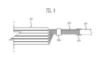
- FIG. 8 is an illustration of another embodiment.
- Coupling members 300 may function to connect electrode tabs to one another while surrounding a tab portion 200, and to connect the tab portion 200 and a large-current tab 400 to each other.
- one half side of one coupling member 300 may surround the tab portion 200, and the other half side of the one coupling member 300 may surround the large-current tab 400. Therefore, the tab portion 200 and the large-current tab 400 can be connected to each other by the medium of the one coupling member 300.
- the welding process between the tab portion 200 and the large-current tab 400 may be omitted, and accordingly, it can be possible to simplify the coupling operation and to reinforce the entire strength.
- the coupling member 300 performs the conducting function between the tab portion 200 and the large-current tab 400. Therefore, the coupling member 300 may be formed of a conductive, for example a metallic material.
- electrode tabs that constitute a tab portion may be connected to one another by simply surrounding the entire tab portion using a coupling member without separate welding or machining operation, so that it is possible to simplify a coupling operation and to reinforce the entire strength.
- Embodiments may provide various modifications of a coupling structure in which a coupling member connects electrode tabs connected and stacked in a stacked-type electrode assembly while surrounding the electrode tabs at the outside of the electrode tabs. Therefore, when the modifications and combinations are related to configurations in which it is possible to simplify a coupling operation and to reinforce the entire strength, they may be included in the scope of the present invention as defined by the claims.
Landscapes
- Chemical & Material Sciences (AREA)
- Chemical Kinetics & Catalysis (AREA)
- Electrochemistry (AREA)
- General Chemical & Material Sciences (AREA)
- Engineering & Computer Science (AREA)
- Manufacturing & Machinery (AREA)
- Connection Of Batteries Or Terminals (AREA)
- Secondary Cells (AREA)
Abstract
Description
- The present invention relates to an electrode assembly, particularly to the coupling structure for electrode tabs of the electrode assembly and a secondary battery using the electrode assembly.
- A secondary battery is a device that converts chemical energy into electrical energy. Unlike primary batteries, secondary batteries are rechargeable and have high voltage and current density. Thus, secondary batteries are widely used in electric appliances such as portable terminals.
- Among these secondary batteries, a lithium secondary battery basically has a structure in which electrode plates are stacked so as to secure a suitable output factor.
- Specifically, in the state in which a plurality of negative electrode plates and a plurality of positive electrode plates are alternately stacked, positive and negative electrode tabs are extracted from the respective positive and negative electrode plates, and the positive or negative electrode tabs are also stacked with one another. Since the positive or negative electrode tabs are simply stacked with one another but separated from one another, they are connected to one another through a separate process.
- The connection between positive or negative electrode tabs is typically made using an ultrasonic welding method. However, a large-capacity battery has a large number of positive and negative electrode tabs, and is thick. Hence, when the positive or negative electrode tabs are connected using only the ultrasonic welding method, it can be difficult to obtain a suitable fastening force, and operational efficiency may be lowered due to a long welding time.
- In order to solve such a problem, a riveting connection method has recently been proposed in which positive or negative electrode tabs are connected to one another by forming through-holes on the same line in positive or negative electrode tabs, and then inserting a separate rivet into the through-holes.
- However, in such a method, the through-holes typically must be formed individually in each of the positive or negative electrode tabs. Therefore, the operation of the method can be inconvenient and the operational time can be increased.
- In one embodiment, a coupling structure for electrode tabs of a stacked-type secondary battery is provided, in which electrode tabs are connected to one another without a separate processing method for connecting the electrode tabs, thus making possible to reduce the inconvenience of a coupling operation and increasing the fastening force among the electrode tabs.
- According to an aspect of the present invention, a coupling structure for electrode tabs of a secondary battery is provided, the coupling structure comprising: an electrode assembly formed by stacking a plurality of electrode plates; a tab portion formed by stacking electrode tabs protruding from one side of the electrode plates of the electrode assembly; and a coupling member that surrounds an outer surface of the tab portion so that the electrode tabs of the tab portion are connected to one another.
- The coupling member may have a frame structure including an upper cover portion that surrounds a top surface of the tab portion, side cover portions extending from each side of opposite sides of the upper cover portion to surround each side of opposite sides of the tab portion, and lower cover portions extending from each of the side cover portions to surround a bottom surface of the tab portion.
- Bent portions may be formed at ends of each of the lower cover portions, wherein the bent portions face each other and bend upwards, and the tab portion is mounted on the bent portions.
- The bent portion may overlap the lower cover portions on an upper surface of the lower cover portions.
- Both end portions of the bent portions may be bent toward the side cover portions.
- The bent portions and the lower cover portions may be stacked into a multiple-layered structure.
- A tab protecting member may be formed on an inner surface of the coupling member and a surface of the tab portion.
- The tab portion positioned in the coupling member may be formed in an arc shape.
- Each of the electrode tabs of the tab portion may include positive and negative electrode tab portions positioned at an interval on each of the electrode plates, and wherein the coupling member may include a first coupling member that surrounds the positive electrode tab portion and a second coupling member connected to the first coupling member to surround the negative electrode tab portion.
- The first and second coupling members may be connected to each other through a connection cover piece.
- The connection cover piece may have a bent portion.
- The portions of the first and second coupling members that respectively surround the positive and negative electrode tab portions of the first and second coupling members may have a circular or arc shape.
- A tab protecting member may be formed between the first and second coupling members and the positive and negative electrode tab portions.
- According to an aspect of the present invention, there is provided a coupling structure for electrode tabs of a secondary battery, the coupling structure including: an electrode assembly formed by stacking a plurality of electrode plates; positive and negative electrode tab portions formed by stacking positive and negative electrode tabs protruding from one sides of the electrode plates of the electrode assembly; large-current tab portions attached to one end of the positive and negative electrode tab portions; and a coupling member that surrounds an outer surface of at least one coupling portion of the positive electrode tab portion, the negative electrode tab portion and large-current tab portions so that the electrode tabs of each of the tab portions are connected to one another.
- A tab protecting member may be formed on an inner surface of the coupling member.
- The coupling member may further include a separate coupling member that surrounds one or more outer surfaces of the positive and negative electrode tab portions.
- According to an aspect of the present invention, there is provided a secondary battery including: an electrode assembly formed by stacking a plurality of electrode plates; positive and negative electrode tab portions each having the coupling member according to any one of the above described embodiments, the positive and negative electrode tab portions being formed by stacking positive and negative electrode tabs protruding from one sides of the electrode plates of the electrode assembly; and a housing that accommodates the electrode assembly such that the positive and negative electrode tab portions are protruding to the exterior of the housing.
- As described above, according to embodiments of the present invention, a coupling member is formed to surround an entire tab portion having stacked electrode tabs without performing a separate processing for connecting the electrode tabs, so that it is possible to simplify the coupling operation and to obtain a high fastening force.
- The accompanying drawings, together with the specification, illustrate certain embodiments of the present invention, and, together with the description, serve to explain principles of the present invention.
-
FIG. 1 is a side schematic view showing the stacked structure of electrode plates and electrode tabs and the formation state of coupling members. -
FIG. 2 is a plan schematic view showing the state in which the coupling members are formed at each tab portion. -
FIGs. 3 to 5 are sectional schematic view showing the structure of a coupling member and the connection structure of electrode tabs through the coupling members shown inFIG 2 . -
FIGS. 6 and 7 are sectional schematic views showing a single coupling member extending across positive and negative electrode tabs. -
Figure 8 illustrates a further embodiment showing the connection of the electrode tabs to a high-current tab. - In the following detailed description, certain embodiments of the present invention have been shown and described, simply by way of illustration. Accordingly, the drawings and description are to be regarded as illustrative in nature and not restrictive. In addition, when an element is referred to as being "on" another element, it can be directly on another element or indirectly on another element with one or more intervening elements interposed therebetween. Also, when an element is referred to as being "connected to" another element, it can be directly connected to another element or indirectly connected to another element with one or more intervening elements interposed therebetween. Hereinafter, like reference numerals refer to like elements. In the drawings, the thickness or size of layers are exaggerated for clarity and not necessarily drawn to scale.
- As shown in
FIGS. 1 and 2 , a stacked-type secondary battery according to an embodiment of the present invention includes anelectrode assembly 100 formed by stacking a plurality of electrode layers, and a plurality oftab portions 200. In this embodiment, theelectrode assembly 100 has a structure in which positive andnegative electrode plates second electrode plates - The plurality of
tab portions 200 may be formed on one side of theelectrode assembly 100 with a structure in which the positive andnegative electrode plates tab portions 200 may be used to collect current generated from the electrode assembly, and include positive and negativeelectrode tab portions - The positive
electrode tab portion 210 may function to collect current generated from each of thepositive electrode plates 110. The positiveelectrode tab portion 210 can have a structure in whichpositive electrode tabs 212 having a thin plate shape are connected to one end portion of thepositive electrode plates 110 and stacked with one another. - The negative
electrode tab portion 220 may function to collect current generated from each of thenegative electrode plates 120. The negativeelectrode tab portion 220 may have a structure in whichnegative electrode tabs 222 having a thin plate shape identical to that of thepositive electrode tabs 212 are connected to one end portion of thenegative electrode plates 120, and stacked with one another. - As the
tab portions 200 are formed into such a structure, the positive and negativeelectrode tab portions electrode assembly 100. - In this embodiment, coupling members are provided to the positive and negative
electrode tab portions tab portions 200. Thecoupling members 300 may function to connect thepositive electrode tabs 212 of the positiveelectrode tab portion 210 to one another and to connect thenegative electrode tabs 222 of the negativeelectrode tab portion 220 to one another. Thecoupling members 300 may include first andsecond coupling members - The
first coupling member 310 may be used to connect thepositive electrode tabs 212 to one another. Thefirst coupling member 310 may be entirely formed into a metal frame structure. As shown inFIG. 3 , the first coupling member may be formed to surround the entirepositive electrode portion 210 at the outside of thepositive electrode portion 210. - Specifically, an
upper cover piece 312 for covering a top surface of the positiveelectrode tab portion 210 may be positioned on the top surface of the positiveelectrode tab portion 210, andside cover pieces 314 may be bent to extend downward at both ends of theupper cover piece 312 to surround both sides of the positiveelectrode tab portion 210. - In addition,
lower cover pieces 316 may be bent to extend toward each other at ends of theside cover pieces 314 to surround a bottom surface of the positiveelectrode tab portion 210. - As the
first coupling member 310 is formed to surround the entire circumference of the positiveelectrode tab portion 210, the positiveelectrode tab portion 210 may be bound by thefirst coupling member 310, thereby maintaining the stacked state of thepositive electrode tabs 212. - As shown in
FIG. 3 ,bent pieces 318 may be further formed to extend upward at ends of thelower cover pieces 316, which face each other, so as to contact the bottom surface of the positiveelectrode tab portion 210. Thus, the positiveelectrode tab portion 210 can be safely mounted on thebent pieces 318. - In such a structure in which the bottom surface of the positive
electrode tab portion 210 is surrounded by only thelower cover pieces 316, the gap between thelower cover pieces 316 can be widened due to the weight of the positiveelectrode tab portion 210, and therefore, the positiveelectrode tab portion 210 may be slipped out of the gap between thelower cover pieces 316. - However, as the
bent pieces 318 are formed to rise vertically from the ends of the respectivelower cover pieces 316, the weight load of the positiveelectrode tab portion 210 can be primarily supported in the vertical direction by thebent pieces 318. Thus, it is possible to minimize widening of the gap between thelower cover pieces 316 due to the load distribution. - The
bent pieces 318 may be formed into a structure in which they are stacked on the upper surfaces of thelower cover pieces 316 for the purpose of load distribution. However, a short circuit between thebent pieces 318 may occur due to contact with an external object. - As shown in
FIG. 4 , thebent pieces 318 may be stacked on the upper surfaces of thelower cover pieces 316. In this case, the strength of thelower cover pieces 316 can be reinforced, and the finishing shape of the ends of thelower cover pieces 316 can be simplified. - Alternatively, the
bent piece 318 and thelower cover piece 316 may be stacked into a double-layered structure, or thebent piece 318 may be repeatedly formed so that thebent pieces 318 and thelower cover piece 316 are stacked into a triple or more-layered structure. - As shown in
FIG. 5 , theentire coupling member 300 may be formed in the shape of an arc so that the positiveelectrode tab portion 210 is also formed in the shape of an arc when thecoupling member 300 surrounds the positiveelectrode tab portion 210, thereby increasing the fastening efficiency between the positiveelectrode tab portion 210 and thecoupling member 300. - In addition, a separate
tab protecting member 330 may be formed on an inner surface of thefirst coupling member 310 regardless of the shape of thefirst coupling member 310, so that it is possible to prevent the surface of a corresponding electrode tab from being damaged by contact between thefirst coupling member 310 and the corresponding electrode tab. - In this embodiment, a synthetic resin tape or the like is used as the
tab protecting member 330, so that it is possible to prevent a short circuit and to minimize the damage of the surface of the electrode tab. - The
second coupling member 320 formed at the negativeelectrode tab portion 220 may be used to connect thenegative electrode tabs 222 of the negativeelectrode tab portion 220 to one another. Thesecond coupling member 320 may be formed into the same structure of thefirst coupling member 310 to surround the negativeelectrode tab portion 220 at the outside of the negativeelectrode tab portion 220. Thus, the negativeelectrode tab portion 220 may be bound by thesecond coupling member 320, thereby maintaining the stacked state of thenegative electrode tabs 222. - The shape of the
second coupling member 320 may also be varied with the same shape as thefirst coupling member 310. Thesecond coupling member 320 may be provided with atab protecting member 330. - The positive and negative
electrode tab portions electrode assembly 100 by the first andsecond coupling members - As described above, the electrode tabs may be connected to one another by surrounding the entire tab portion at the outside of the tab portion without separate welding or machining of the electrode tabs, so that it is possible to simplify a coupling operation and to prevent a coupling portion from being broken by external impact.
- For reference, a plurality of
coupling members 300 may be provided to each of the positive and negativeelectrode tab portions FIGS. 1 and 2 . In this case, it is possible to reinforce the entire strength. -
FIG. 6 is a view showing still another embodiment. Unlike the aforementioned embodiment in which thecoupling members 300 are respectively provided to the positive and negativeelectrode tab portions coupling member 300 may simultaneously surround the positive and negativeelectrode tab portions electrode tab portions - To this end, the
coupling member 300 may include afirst coupling member 310 that surrounds the positiveelectrode tab portion 210 and asecond coupling member 320 that surrounds the negativeelectrode tab portion 220 as described in the aforementioned embodiment. Aconnection cover piece 319 that connects the first andsecond coupling members second coupling members - More specifically, in an embodiment in which the first and
second coupling members electrode tab portions electrode tab portions connection cover piece 319 positioned between the first andsecond coupling members second coupling members - Thus, the
coupling member 300 can connect the positive and negativeelectrode tab portions connection cover piece 319 while individually surrounding the positive and negativeelectrode tab portions - In this embodiment, a separate
tab protecting member 330 may be provided to the inner circumferential surfaces of the first andsecond coupling members connection cover piece 319, so that it is possible to prevent a short circuit and to prevent damage of the surfaces of the positive andnegative electrode tabs - For reference, in the embodiment shown in
FIG. 6 , thecoupling members electrode tab portions coupling members FIGS. 3 to 5 . - As shown in
FIG. 7 , abent portion 319a may be formed at theconnection cover piece 319, so that it is possible to reinforce the strength of theconnection cover piece 319 and to enhance the entire fixing force of thecoupling members - A plurality of
first coupling members 310 and a plurality ofsecond coupling members 320, which have such a shape, can be formed on the positive and negativeelectrode tab portions -
FIG. 8 is an illustration of another embodiment. Couplingmembers 300 may function to connect electrode tabs to one another while surrounding atab portion 200, and to connect thetab portion 200 and a large-current tab 400 to each other. - In this case, one half side of one
coupling member 300 may surround thetab portion 200, and the other half side of the onecoupling member 300 may surround the large-current tab 400. Therefore, thetab portion 200 and the large-current tab 400 can be connected to each other by the medium of the onecoupling member 300. - Thus, the welding process between the
tab portion 200 and the large-current tab 400 may be omitted, and accordingly, it can be possible to simplify the coupling operation and to reinforce the entire strength. - In this embodiment, the
coupling member 300 performs the conducting function between thetab portion 200 and the large-current tab 400. Therefore, thecoupling member 300 may be formed of a conductive, for example a metallic material. - As described above, electrode tabs that constitute a tab portion may be connected to one another by simply surrounding the entire tab portion using a coupling member without separate welding or machining operation, so that it is possible to simplify a coupling operation and to reinforce the entire strength.
- Various features of the present invention described above may be modified and combined by those skilled in the art. Embodiments may provide various modifications of a coupling structure in which a coupling member connects electrode tabs connected and stacked in a stacked-type electrode assembly while surrounding the electrode tabs at the outside of the electrode tabs. Therefore, when the modifications and combinations are related to configurations in which it is possible to simplify a coupling operation and to reinforce the entire strength, they may be included in the scope of the present invention as defined by the claims.
- While the present invention has been described in connection with certain embodiments, it is to be understood that the invention is not limited to the disclosed embodiments, but, on the contrary, is intended to cover various modifications and equivalent arrangements included within the scope of the appended claims.
Claims (15)
- An electrode assembly comprising:a plurality of stacked electrode plates (110, 120);a tab portion (200) comprising stacked electrode tabs (210, 220) protruding from one side of the electrode plates; anda coupling member (300) that surrounds an outer surface of the tab portion so that the electrode tabs of the tab portion are connected to one another.
- The electrode assembly according to claim 1, wherein the coupling member has a frame structure comprising an upper cover portion that surrounds a top surface of the tab portion, side cover portions extending from each side of opposite sides of the upper cover portion to respectively surround each side of opposite sides of the tab portion, and lower cover portions extending from each of the side cover portions to surround a bottom surface of the tab portion.
- The electrode assembly according to claim 2, wherein bent portions are formed at ends of each of the lower cover portions, wherein the bent portions face each other and bend upwards, and the tab portion is mounted on the bent portions.
- The electrode assembly according to claim 3, wherein the bent portions overlap the lower cover portions on an upper surface of the lower cover portions.
- The electrode assembly according to claim 3 or 4, wherein the end portions of the bent portions are bent towards the side cover portions.
- The electrode assembly according to claim 3, 4 or 5, wherein the bent portions and the lower cover portions are stacked into a multiple-layered structure.
- The electrode assembly according to any one of the preceding claims, wherein a tab protecting member (330) is formed on an inner surface of the coupling member and a surface of the tab portion.
- The electrode assembly according to any one of the preceding claims, wherein the tab portion positioned in the coupling member is formed in an arc shape.
- The electrode assembly according to any one of the preceding claims, wherein each of the electrode tabs of the tab portion comprises positive and negative electrode tab portions positioned at an interval on each of the electrode plates, and wherein the coupling member comprises a first coupling member that surrounds the positive electrode tab portion and a second coupling member connected to the first coupling member to surround the negative electrode tab portion.
- The electrode assembly according to claim 9, wherein the first and second coupling members are connected to each other through a connection cover piece (319), wherein the connection cover piece may have a bent portion (319a).
- The electrode assembly according to claim 9 or 10, wherein portions of the first and second coupling members that respectively surround the positive and negative electrode tab portions of the first and second coupling members have a circular or arc shape.
- The electrode assembly according to any one of claims 9 to 11, wherein a tab protecting member (330) is formed between the first and second coupling members and the positive and negative electrode tab portions.
- The electrode assembly of any one of the preceding claims, further comprising:a large-current tab (400);wherein the coupling member is arranged to surround an outer surface of the tab portion and the large-current tab so that the electrode tabs of the tab portion are connected to one another and to the large current tab.
- The electrode assembly according to claim 13, wherein the coupling member further comprises a separate coupling member that surrounds one or more outer surfaces of positive and negative electrode tab portions comprised in the tab portion.
- A secondary battery comprising:an electrode assembly according to any one of the preceding claims; anda housing that accommodates the electrode assembly such that positive and negative electrode tab portions protrude to the exterior of the housing.
Applications Claiming Priority (1)
| Application Number | Priority Date | Filing Date | Title |
|---|---|---|---|
| KR20100057672A KR101122811B1 (en) | 2010-06-17 | 2010-06-17 | coupling member for electrode tabs of secondary battery and secondary battery using the same |
Publications (2)
| Publication Number | Publication Date |
|---|---|
| EP2398092A1 true EP2398092A1 (en) | 2011-12-21 |
| EP2398092B1 EP2398092B1 (en) | 2013-09-11 |
Family
ID=44487073
Family Applications (1)
| Application Number | Title | Priority Date | Filing Date |
|---|---|---|---|
| EP20110164698 Active EP2398092B1 (en) | 2010-06-17 | 2011-05-04 | Electrode assembly and secondary battery using the same |
Country Status (5)
| Country | Link |
|---|---|
| US (1) | US9029006B2 (en) |
| EP (1) | EP2398092B1 (en) |
| JP (1) | JP5362679B2 (en) |
| KR (1) | KR101122811B1 (en) |
| CN (1) | CN102290551B (en) |
Families Citing this family (12)
| Publication number | Priority date | Publication date | Assignee | Title |
|---|---|---|---|---|
| KR101809208B1 (en) | 2015-06-16 | 2017-12-14 | 주식회사 엘지화학 | Secondary battery and method for fabricating the same |
| JP6857294B2 (en) * | 2016-02-29 | 2021-04-14 | 株式会社Gsユアサ | Power storage element and manufacturing method of power storage element |
| KR102663722B1 (en) * | 2016-09-05 | 2024-05-07 | 삼성에스디아이 주식회사 | Secondary Battery |
| CN113261138A (en) * | 2019-01-15 | 2021-08-13 | 松下知识产权经营株式会社 | Secondary battery |
| US11065460B2 (en) * | 2019-05-30 | 2021-07-20 | Medtronic, Inc. | Battery assembly for medical device |
| CN210429950U (en) * | 2019-07-22 | 2020-04-28 | 宁德新能源科技有限公司 | Laminated tab, pole piece, battery core and battery |
| CN112542656B (en) * | 2020-11-18 | 2022-05-17 | 东风汽车集团有限公司 | Utmost point ear limiting plate, battery module, battery package and car |
| CN112542661B (en) * | 2020-11-18 | 2022-05-20 | 东风汽车集团有限公司 | Laminate polymer core opposition fixed block, battery module, battery package and car |
| CN112542657B (en) * | 2020-11-18 | 2022-05-20 | 东风汽车集团有限公司 | A method and device for cascading and grouping soft-packed cells |
| CN112542662B (en) * | 2020-11-18 | 2022-05-17 | 东风汽车集团有限公司 | A soft-pack battery cell series fixing device, battery module, battery pack and automobile |
| KR102733272B1 (en) * | 2021-10-05 | 2024-11-25 | 삼성에스디아이 주식회사 | Secondary battery |
| KR20250026570A (en) * | 2023-08-17 | 2025-02-25 | 주식회사 엘지에너지솔루션 | Electrode assembly, secondary battery including the electrode assembly, and method for manufacturing the electrode assembly |
Citations (3)
| Publication number | Priority date | Publication date | Assignee | Title |
|---|---|---|---|---|
| EP0199476A2 (en) * | 1985-04-20 | 1986-10-29 | LUCAS INDUSTRIES public limited company | Alkaline electric storage cells |
| US20090169991A1 (en) * | 2007-12-27 | 2009-07-02 | Industrial Technology Research Institute | Flexible envelope type battery and electrically conductible sealing structure thereof and assembling method thereof |
| EP2337106A2 (en) * | 2009-10-13 | 2011-06-22 | Samsung SDI Co., Ltd. | Rechargeable battery |
Family Cites Families (11)
| Publication number | Priority date | Publication date | Assignee | Title |
|---|---|---|---|---|
| US4098966A (en) * | 1977-11-14 | 1978-07-04 | General Motors Corporation | Welded battery elements and process |
| US5503948A (en) * | 1994-08-02 | 1996-04-02 | Microelectronics And Computer Technology Corporation | Thin cell electrochemical battery system; and method of interconnecting multiple thin cells |
| JPH08167408A (en) * | 1994-12-15 | 1996-06-25 | Sony Corp | Sealed prismatic battery electrode body and method of manufacturing the same |
| JPH08167407A (en) * | 1994-12-15 | 1996-06-25 | Sony Corp | Sealed prismatic battery electrode body and method of manufacturing the same |
| CA2384215A1 (en) * | 2002-04-30 | 2003-10-30 | Richard Laliberte | Electrochemical bundle and method for making same |
| JP3963165B2 (en) | 2003-10-10 | 2007-08-22 | 日産自動車株式会社 | Assembled battery |
| FR2876221B1 (en) | 2004-10-06 | 2006-12-22 | Batscap Sa | BATTERY MODULE COMPRISING AN ENERGY STORAGE ELEMENT WHOSE CONTACT IS EFFECTED BY CLAMPING LAYERS BETWEEN THEM |
| KR20060033642A (en) | 2004-10-15 | 2006-04-19 | 주식회사 에너랜드 | Electrode Tab Treatment Method of Multilayer Lithium Secondary Battery |
| KR100818196B1 (en) | 2006-08-11 | 2008-04-01 | 주식회사 코캄 | Method and structure of connecting grid and electrode tab of secondary battery |
| CN201112964Y (en) | 2007-08-16 | 2008-09-10 | 达昌电子科技(苏州)有限公司 | Electric connector structure |
| KR100989841B1 (en) * | 2008-01-04 | 2010-10-29 | 삼성에스디아이 주식회사 | Compression pin and secondary battery having same |
-
2010
- 2010-06-17 KR KR20100057672A patent/KR101122811B1/en active Active
- 2010-10-22 JP JP2010237305A patent/JP5362679B2/en active Active
- 2010-12-30 US US12/982,789 patent/US9029006B2/en active Active
-
2011
- 2011-01-20 CN CN201110026674.5A patent/CN102290551B/en active Active
- 2011-05-04 EP EP20110164698 patent/EP2398092B1/en active Active
Patent Citations (3)
| Publication number | Priority date | Publication date | Assignee | Title |
|---|---|---|---|---|
| EP0199476A2 (en) * | 1985-04-20 | 1986-10-29 | LUCAS INDUSTRIES public limited company | Alkaline electric storage cells |
| US20090169991A1 (en) * | 2007-12-27 | 2009-07-02 | Industrial Technology Research Institute | Flexible envelope type battery and electrically conductible sealing structure thereof and assembling method thereof |
| EP2337106A2 (en) * | 2009-10-13 | 2011-06-22 | Samsung SDI Co., Ltd. | Rechargeable battery |
Also Published As
| Publication number | Publication date |
|---|---|
| KR20110137639A (en) | 2011-12-23 |
| JP5362679B2 (en) | 2013-12-11 |
| CN102290551A (en) | 2011-12-21 |
| CN102290551B (en) | 2014-08-20 |
| KR101122811B1 (en) | 2012-03-21 |
| US20110311859A1 (en) | 2011-12-22 |
| JP2012004096A (en) | 2012-01-05 |
| EP2398092B1 (en) | 2013-09-11 |
| US9029006B2 (en) | 2015-05-12 |
Similar Documents
| Publication | Publication Date | Title |
|---|---|---|
| EP2398092B1 (en) | Electrode assembly and secondary battery using the same | |
| JP5297471B2 (en) | Secondary battery | |
| KR100599752B1 (en) | Secondary Battery and Electrode Assembly Used in the Same | |
| EP2204863B1 (en) | Battery module | |
| US8771863B2 (en) | Battery module and manufacturing method of battery module | |
| KR101359710B1 (en) | Rechargeable battery case and rechargeable battery assembly | |
| US9070939B2 (en) | Battery module | |
| EP2731174B1 (en) | Secondary battery pack | |
| CN103718342B (en) | secondary battery pack | |
| JP5149924B2 (en) | Cylindrical secondary battery and manufacturing method thereof | |
| EP2731172B1 (en) | Secondary battery pack | |
| JP2010165679A (en) | Battery pack | |
| KR20190053124A (en) | Battery pack of one body busbar for energy storage system | |
| EP1760804B1 (en) | No-welding contact type secondary battery | |
| JP2014512660A (en) | Battery cell sensing board | |
| KR101890844B1 (en) | An electrode assembly with improved safety in use by structure of outermost electrodes and material of current collectors, and lithium ion battery with the electrode assembly | |
| US8715851B2 (en) | Battery pack and battery pack stack | |
| US12244034B2 (en) | Buffer member and electrical storage module | |
| US9099723B2 (en) | Battery pack and manufacturing method thereof | |
| JP7743604B2 (en) | Cylindrical battery cell, and battery pack and automobile including the same | |
| KR20000021401A (en) | Method for manufacturing electrode assembly unit and the electrode assembly unit and battery using the electrode assembly | |
| KR101528003B1 (en) | Interconnect for electrode-tabelectrochemical cell using the same | |
| KR100589392B1 (en) | Electrode assembly and secondary battery having same | |
| JP2018147743A (en) | Electrode and nonaqueous electrolyte secondary battery | |
| JP7798435B2 (en) | Battery Module |
Legal Events
| Date | Code | Title | Description |
|---|---|---|---|
| AK | Designated contracting states |
Kind code of ref document: A1 Designated state(s): AL AT BE BG CH CY CZ DE DK EE ES FI FR GB GR HR HU IE IS IT LI LT LU LV MC MK MT NL NO PL PT RO RS SE SI SK SM TR |
|
| AX | Request for extension of the european patent |
Extension state: BA ME |
|
| PUAI | Public reference made under article 153(3) epc to a published international application that has entered the european phase |
Free format text: ORIGINAL CODE: 0009012 |
|
| 17P | Request for examination filed |
Effective date: 20120321 |
|
| REG | Reference to a national code |
Ref country code: DE Ref legal event code: R079 Ref document number: 602011002963 Country of ref document: DE Free format text: PREVIOUS MAIN CLASS: H01M0002300000 Ipc: H01M0002260000 |
|
| GRAP | Despatch of communication of intention to grant a patent |
Free format text: ORIGINAL CODE: EPIDOSNIGR1 |
|
| RIC1 | Information provided on ipc code assigned before grant |
Ipc: H01M 2/26 20060101AFI20130325BHEP |
|
| INTG | Intention to grant announced |
Effective date: 20130410 |
|
| GRAS | Grant fee paid |
Free format text: ORIGINAL CODE: EPIDOSNIGR3 |
|
| GRAA | (expected) grant |
Free format text: ORIGINAL CODE: 0009210 |
|
| AK | Designated contracting states |
Kind code of ref document: B1 Designated state(s): AL AT BE BG CH CY CZ DE DK EE ES FI FR GB GR HR HU IE IS IT LI LT LU LV MC MK MT NL NO PL PT RO RS SE SI SK SM TR |
|
| REG | Reference to a national code |
Ref country code: GB Ref legal event code: FG4D |
|
| REG | Reference to a national code |
Ref country code: CH Ref legal event code: EP |
|
| REG | Reference to a national code |
Ref country code: AT Ref legal event code: REF Ref document number: 632061 Country of ref document: AT Kind code of ref document: T Effective date: 20130915 |
|
| REG | Reference to a national code |
Ref country code: IE Ref legal event code: FG4D |
|
| REG | Reference to a national code |
Ref country code: DE Ref legal event code: R096 Ref document number: 602011002963 Country of ref document: DE Effective date: 20131107 |
|
| PG25 | Lapsed in a contracting state [announced via postgrant information from national office to epo] |
Ref country code: LT Free format text: LAPSE BECAUSE OF FAILURE TO SUBMIT A TRANSLATION OF THE DESCRIPTION OR TO PAY THE FEE WITHIN THE PRESCRIBED TIME-LIMIT Effective date: 20130911 Ref country code: HR Free format text: LAPSE BECAUSE OF FAILURE TO SUBMIT A TRANSLATION OF THE DESCRIPTION OR TO PAY THE FEE WITHIN THE PRESCRIBED TIME-LIMIT Effective date: 20130911 Ref country code: CY Free format text: LAPSE BECAUSE OF FAILURE TO SUBMIT A TRANSLATION OF THE DESCRIPTION OR TO PAY THE FEE WITHIN THE PRESCRIBED TIME-LIMIT Effective date: 20130731 Ref country code: NO Free format text: LAPSE BECAUSE OF FAILURE TO SUBMIT A TRANSLATION OF THE DESCRIPTION OR TO PAY THE FEE WITHIN THE PRESCRIBED TIME-LIMIT Effective date: 20131211 Ref country code: SE Free format text: LAPSE BECAUSE OF FAILURE TO SUBMIT A TRANSLATION OF THE DESCRIPTION OR TO PAY THE FEE WITHIN THE PRESCRIBED TIME-LIMIT Effective date: 20130911 |
|
| REG | Reference to a national code |
Ref country code: NL Ref legal event code: VDEP Effective date: 20130911 |
|
| REG | Reference to a national code |
Ref country code: AT Ref legal event code: MK05 Ref document number: 632061 Country of ref document: AT Kind code of ref document: T Effective date: 20130911 |
|
| REG | Reference to a national code |
Ref country code: LT Ref legal event code: MG4D |
|
| PG25 | Lapsed in a contracting state [announced via postgrant information from national office to epo] |
Ref country code: SI Free format text: LAPSE BECAUSE OF FAILURE TO SUBMIT A TRANSLATION OF THE DESCRIPTION OR TO PAY THE FEE WITHIN THE PRESCRIBED TIME-LIMIT Effective date: 20130911 Ref country code: FI Free format text: LAPSE BECAUSE OF FAILURE TO SUBMIT A TRANSLATION OF THE DESCRIPTION OR TO PAY THE FEE WITHIN THE PRESCRIBED TIME-LIMIT Effective date: 20130911 Ref country code: LV Free format text: LAPSE BECAUSE OF FAILURE TO SUBMIT A TRANSLATION OF THE DESCRIPTION OR TO PAY THE FEE WITHIN THE PRESCRIBED TIME-LIMIT Effective date: 20130911 Ref country code: GR Free format text: LAPSE BECAUSE OF FAILURE TO SUBMIT A TRANSLATION OF THE DESCRIPTION OR TO PAY THE FEE WITHIN THE PRESCRIBED TIME-LIMIT Effective date: 20131212 |
|
| PG25 | Lapsed in a contracting state [announced via postgrant information from national office to epo] |
Ref country code: CY Free format text: LAPSE BECAUSE OF FAILURE TO SUBMIT A TRANSLATION OF THE DESCRIPTION OR TO PAY THE FEE WITHIN THE PRESCRIBED TIME-LIMIT Effective date: 20130911 Ref country code: BE Free format text: LAPSE BECAUSE OF FAILURE TO SUBMIT A TRANSLATION OF THE DESCRIPTION OR TO PAY THE FEE WITHIN THE PRESCRIBED TIME-LIMIT Effective date: 20130911 |
|
| PG25 | Lapsed in a contracting state [announced via postgrant information from national office to epo] |
Ref country code: IS Free format text: LAPSE BECAUSE OF FAILURE TO SUBMIT A TRANSLATION OF THE DESCRIPTION OR TO PAY THE FEE WITHIN THE PRESCRIBED TIME-LIMIT Effective date: 20140111 Ref country code: CZ Free format text: LAPSE BECAUSE OF FAILURE TO SUBMIT A TRANSLATION OF THE DESCRIPTION OR TO PAY THE FEE WITHIN THE PRESCRIBED TIME-LIMIT Effective date: 20130911 Ref country code: EE Free format text: LAPSE BECAUSE OF FAILURE TO SUBMIT A TRANSLATION OF THE DESCRIPTION OR TO PAY THE FEE WITHIN THE PRESCRIBED TIME-LIMIT Effective date: 20130911 Ref country code: NL Free format text: LAPSE BECAUSE OF FAILURE TO SUBMIT A TRANSLATION OF THE DESCRIPTION OR TO PAY THE FEE WITHIN THE PRESCRIBED TIME-LIMIT Effective date: 20130911 Ref country code: RO Free format text: LAPSE BECAUSE OF FAILURE TO SUBMIT A TRANSLATION OF THE DESCRIPTION OR TO PAY THE FEE WITHIN THE PRESCRIBED TIME-LIMIT Effective date: 20130911 Ref country code: SK Free format text: LAPSE BECAUSE OF FAILURE TO SUBMIT A TRANSLATION OF THE DESCRIPTION OR TO PAY THE FEE WITHIN THE PRESCRIBED TIME-LIMIT Effective date: 20130911 |
|
| PG25 | Lapsed in a contracting state [announced via postgrant information from national office to epo] |
Ref country code: ES Free format text: LAPSE BECAUSE OF FAILURE TO SUBMIT A TRANSLATION OF THE DESCRIPTION OR TO PAY THE FEE WITHIN THE PRESCRIBED TIME-LIMIT Effective date: 20130911 Ref country code: AT Free format text: LAPSE BECAUSE OF FAILURE TO SUBMIT A TRANSLATION OF THE DESCRIPTION OR TO PAY THE FEE WITHIN THE PRESCRIBED TIME-LIMIT Effective date: 20130911 Ref country code: PL Free format text: LAPSE BECAUSE OF FAILURE TO SUBMIT A TRANSLATION OF THE DESCRIPTION OR TO PAY THE FEE WITHIN THE PRESCRIBED TIME-LIMIT Effective date: 20130911 |
|
| REG | Reference to a national code |
Ref country code: DE Ref legal event code: R097 Ref document number: 602011002963 Country of ref document: DE |
|
| PG25 | Lapsed in a contracting state [announced via postgrant information from national office to epo] |
Ref country code: PT Free format text: LAPSE BECAUSE OF FAILURE TO SUBMIT A TRANSLATION OF THE DESCRIPTION OR TO PAY THE FEE WITHIN THE PRESCRIBED TIME-LIMIT Effective date: 20140113 |
|
| PLBE | No opposition filed within time limit |
Free format text: ORIGINAL CODE: 0009261 |
|
| STAA | Information on the status of an ep patent application or granted ep patent |
Free format text: STATUS: NO OPPOSITION FILED WITHIN TIME LIMIT |
|
| 26N | No opposition filed |
Effective date: 20140612 |
|
| PG25 | Lapsed in a contracting state [announced via postgrant information from national office to epo] |
Ref country code: IT Free format text: LAPSE BECAUSE OF FAILURE TO SUBMIT A TRANSLATION OF THE DESCRIPTION OR TO PAY THE FEE WITHIN THE PRESCRIBED TIME-LIMIT Effective date: 20130911 |
|
| REG | Reference to a national code |
Ref country code: DE Ref legal event code: R097 Ref document number: 602011002963 Country of ref document: DE Effective date: 20140612 |
|
| PG25 | Lapsed in a contracting state [announced via postgrant information from national office to epo] |
Ref country code: DK Free format text: LAPSE BECAUSE OF FAILURE TO SUBMIT A TRANSLATION OF THE DESCRIPTION OR TO PAY THE FEE WITHIN THE PRESCRIBED TIME-LIMIT Effective date: 20130911 |
|
| PG25 | Lapsed in a contracting state [announced via postgrant information from national office to epo] |
Ref country code: LU Free format text: LAPSE BECAUSE OF FAILURE TO SUBMIT A TRANSLATION OF THE DESCRIPTION OR TO PAY THE FEE WITHIN THE PRESCRIBED TIME-LIMIT Effective date: 20140504 |
|
| REG | Reference to a national code |
Ref country code: CH Ref legal event code: PL |
|
| PG25 | Lapsed in a contracting state [announced via postgrant information from national office to epo] |
Ref country code: CH Free format text: LAPSE BECAUSE OF NON-PAYMENT OF DUE FEES Effective date: 20140531 Ref country code: MC Free format text: LAPSE BECAUSE OF FAILURE TO SUBMIT A TRANSLATION OF THE DESCRIPTION OR TO PAY THE FEE WITHIN THE PRESCRIBED TIME-LIMIT Effective date: 20130911 Ref country code: LI Free format text: LAPSE BECAUSE OF NON-PAYMENT OF DUE FEES Effective date: 20140531 |
|
| REG | Reference to a national code |
Ref country code: IE Ref legal event code: MM4A |
|
| PG25 | Lapsed in a contracting state [announced via postgrant information from national office to epo] |
Ref country code: IE Free format text: LAPSE BECAUSE OF NON-PAYMENT OF DUE FEES Effective date: 20140504 |
|
| PG25 | Lapsed in a contracting state [announced via postgrant information from national office to epo] |
Ref country code: MT Free format text: LAPSE BECAUSE OF FAILURE TO SUBMIT A TRANSLATION OF THE DESCRIPTION OR TO PAY THE FEE WITHIN THE PRESCRIBED TIME-LIMIT Effective date: 20130911 |
|
| REG | Reference to a national code |
Ref country code: FR Ref legal event code: PLFP Year of fee payment: 6 |
|
| PG25 | Lapsed in a contracting state [announced via postgrant information from national office to epo] |
Ref country code: SM Free format text: LAPSE BECAUSE OF FAILURE TO SUBMIT A TRANSLATION OF THE DESCRIPTION OR TO PAY THE FEE WITHIN THE PRESCRIBED TIME-LIMIT Effective date: 20130911 |
|
| PG25 | Lapsed in a contracting state [announced via postgrant information from national office to epo] |
Ref country code: RS Free format text: LAPSE BECAUSE OF NON-PAYMENT OF DUE FEES Effective date: 20130911 Ref country code: BG Free format text: LAPSE BECAUSE OF FAILURE TO SUBMIT A TRANSLATION OF THE DESCRIPTION OR TO PAY THE FEE WITHIN THE PRESCRIBED TIME-LIMIT Effective date: 20130911 |
|
| PG25 | Lapsed in a contracting state [announced via postgrant information from national office to epo] |
Ref country code: HU Free format text: LAPSE BECAUSE OF FAILURE TO SUBMIT A TRANSLATION OF THE DESCRIPTION OR TO PAY THE FEE WITHIN THE PRESCRIBED TIME-LIMIT; INVALID AB INITIO Effective date: 20110504 Ref country code: TR Free format text: LAPSE BECAUSE OF FAILURE TO SUBMIT A TRANSLATION OF THE DESCRIPTION OR TO PAY THE FEE WITHIN THE PRESCRIBED TIME-LIMIT Effective date: 20130911 |
|
| REG | Reference to a national code |
Ref country code: FR Ref legal event code: PLFP Year of fee payment: 7 |
|
| REG | Reference to a national code |
Ref country code: FR Ref legal event code: PLFP Year of fee payment: 8 |
|
| PG25 | Lapsed in a contracting state [announced via postgrant information from national office to epo] |
Ref country code: MK Free format text: LAPSE BECAUSE OF FAILURE TO SUBMIT A TRANSLATION OF THE DESCRIPTION OR TO PAY THE FEE WITHIN THE PRESCRIBED TIME-LIMIT Effective date: 20130911 |
|
| PG25 | Lapsed in a contracting state [announced via postgrant information from national office to epo] |
Ref country code: AL Free format text: LAPSE BECAUSE OF FAILURE TO SUBMIT A TRANSLATION OF THE DESCRIPTION OR TO PAY THE FEE WITHIN THE PRESCRIBED TIME-LIMIT Effective date: 20130911 |
|
| REG | Reference to a national code |
Ref country code: DE Ref legal event code: R079 Ref document number: 602011002963 Country of ref document: DE Free format text: PREVIOUS MAIN CLASS: H01M0002260000 Ipc: H01M0050531000 |
|
| P01 | Opt-out of the competence of the unified patent court (upc) registered |
Effective date: 20230528 |
|
| PGFP | Annual fee paid to national office [announced via postgrant information from national office to epo] |
Ref country code: DE Payment date: 20250429 Year of fee payment: 15 |
|
| PGFP | Annual fee paid to national office [announced via postgrant information from national office to epo] |
Ref country code: GB Payment date: 20250501 Year of fee payment: 15 |
|
| PGFP | Annual fee paid to national office [announced via postgrant information from national office to epo] |
Ref country code: FR Payment date: 20250508 Year of fee payment: 15 |