EP2397948B1 - Elektrischer Stecker, System und Verwendung eines elektrischen Steckers - Google Patents
Elektrischer Stecker, System und Verwendung eines elektrischen Steckers Download PDFInfo
- Publication number
- EP2397948B1 EP2397948B1 EP10006289A EP10006289A EP2397948B1 EP 2397948 B1 EP2397948 B1 EP 2397948B1 EP 10006289 A EP10006289 A EP 10006289A EP 10006289 A EP10006289 A EP 10006289A EP 2397948 B1 EP2397948 B1 EP 2397948B1
- Authority
- EP
- European Patent Office
- Prior art keywords
- electrical connector
- connector
- galvanic
- networking device
- local networking
- Prior art date
- Legal status (The legal status is an assumption and is not a legal conclusion. Google has not performed a legal analysis and makes no representation as to the accuracy of the status listed.)
- Active
Links
Images

Classifications
-
- G—PHYSICS
- G06—COMPUTING OR CALCULATING; COUNTING
- G06F—ELECTRIC DIGITAL DATA PROCESSING
- G06F13/00—Interconnection of, or transfer of information or other signals between, memories, input/output devices or central processing units
- G06F13/38—Information transfer, e.g. on bus
- G06F13/40—Bus structure
- G06F13/4063—Device-to-bus coupling
- G06F13/4068—Electrical coupling
- G06F13/4086—Bus impedance matching, e.g. termination
Definitions
- the present invention relates to an electrical connector for providing data communication between a local networking device and a telephone network, a system comprising an electrical connector and the use of an electrical connector for Digital Subscriber Line applications.
- WAN wide area networks
- Suchlike electrical connector cables are designed very simple. Usually, they comprise a cable with at least two wires, wherein each free end of the cable is provided with a plug connector.
- One of these plug connectors is configured to be connected to a corresponding socket of the home gateway, whereas the other of these plug connectors is configured to be connected to a telephone socket which is connected to a subscriber line of the telephone network.
- the galvanic signatures are provided by galvanic signature circuits which are permanently integrated into the local network devices.
- the operator of the telephone network is able to measure the galvanic signature and verifies that the local networking device is enabled and that the transmission line works.
- the operator directly detects the capacity of the galvanic signature circuit, as well as the break voltage of Zener diodes which are provided by the galvanic signature circuit. Therefore, the usage of a DSL-Splitter is not necessary.
- WO01/08390 discloses a home network connecting devices providing a galvanic signature circuit where two Zener diodes are connected in an opposite manner.
- US-4142220 discloses a home network connecting devices providing a surge arrester.
- the object of the present invention is achieved by an electrical connector for providing data communication between a local networking device and a telephone network as defined by claim 1.
- the galvanic signature of the galvanic signature circuit is assigned to the electrical connector and not to the local networking device. If the galvanic signature should be changed only the comparatively cheap electrical connector has to be replaced instead of replacing the whole expensive local networking device. Consequently, hardware costs and installation effort can be saved. It is an advantage of the present invention that implementing the galvanic signature circuit into the electrical connector enables an exclusively splitter-free connected Home Gateway to be identified as a line termination in electronic line check. Using the galvanic signature, it can be determined whether the Home Gateway is connected with the subscriber line or whether there is a line interruption.
- the electrical connector is a connection cable for Digital Subscriber Line applications.
- the surge arrestor is provided within the electrical connector and not in the local networking device. If there is an overvoltage on the subscriber line, the overvoltage is discharged by the surge arrestor of the electrical connector already in the area of the electrical connector and does not even reach the local networking device. Therefore, protection of the local networking device increases. If the surge arrestor should be burned by the overvoltage, the electrical connector can easily and cost-efficiently be replaced without any installation efforts.
- the surge arrestor preferably comprises a Gas-Discharge-Tube.
- the electrical connector is a connection cable for Digital Subscriber Line applications.
- the first connector comprises plug-in telecommunication connection unit for connecting the electrical connector to a subscriber line of the telephone network.
- the telecommunication connection preferably comprises a TAE male connector. It is thereby advantageously possible that the electrical connector is easily pluggable into standard TAE sockets.
- the second connector comprises a RJ45 male connector.
- the second connector is pluggable directly into a RJ45 socket of the local networking device.
- the second connector comprises a RJ45 female connector, so that the RJ45 male connector of a standard data cable e.g. included in delivery of the local networking device, is pluggable directly into the second connector.
- the RJ45 female connector is hereby integrated in a housing of the plug-in telecommunication connection unit.
- the local networking device preferably comprises a residential gateway and particularly preferably a DSL router, a DSL modem, a personal computer and/or the like.
- the residential gateway is independent from the galvanic signature and/or from the surge arrestor. So, a certain residential gateway is usable with changing galvanic signatures, wherein the actual galvanic signature only depends on the currently used electrical connector.
- the electrical connector comprises a transmission cable having at least two wires provided between the first and the second connector, wherein the galvanic signature circuit comprises two Zener diodes provided in series between the two wires of the transmission cable in such a manner, that the pass direction of the two Zener diodes are opposite to each other.
- the two Zener diodes are connected in parallel with a first capacitor and/or wherein the two Zener diodes are connected in series with a second capacitor and/or with an ohmic resistor. If one of these components, e.g. the Zener diodes becomes broken, only the electrical connector has to be replaced and not the expensive local networking device.
- the Gas-Discharge-Tube is connected to each of the two wires of the cable.
- the galvanic signature and/or the surge arrestor are integrated into the telecommunication connection unit and preferably into the TAE connector, because in the TAE connector is enough installation space to accommodate the above mentioned components.
- Another object of the present invention is a system for providing Digital Subscriber Line applications comprising a local networking device, a telephone network and an electrical connector according to the present invention, wherein the electrical connector is configured to provide data transmission between the local networking device and the telephone network for the Digital Subscriber Line applications.
- the local networking device is independent of the galvanic signature and of the surge arrestor. If the galvanic signature should be modified or if the galvanic signature circuit or the surge arrestor gets broken, only the comparatively cheap electrical connector and not the comparatively expensive local networking device must be replaced.
- Another object of the present invention is the use of an electrical connector according to the present invention as a connection cable between a local networking device and a telephone network for Digital Subscriber Line applications.
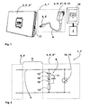
- Figure 1 schematically illustrates a system comprising an electrical connector according to an exemplary embodiment of the present invention.
- Figure 2 schematically illustrates in detail the electrical connector according to the exemplary embodiment of the present invention.
- FIG. 3 schematically illustrates in detail the TAE male connector of the electrical connector according to the exemplary embodiment of the present invention. Both male connector design of the TAE plug 4 could be possible 50 or 4.
- FIG. 1 schematically shows a system for providing Digital Subscriber Line (DSL) applications.
- the system comprises a local networking device 2, a telephone network 3 and an electrical connector 1 connecting the locale networking device 2 with the telephone network 3.
- the local networking device 2 is a residential gateway 2', also referred to as Home Gateway, in the form of a DSL router 2".
- the DSL router 2" is e.g. connected to a local network (LAN), in particular to a wireless network (WLAN).
- the telephone network 3 is a wide area network (WAN) providing a subscriber line 7 which is connectable via a TAE socket 16.
- the electrical connector 1 is a connection cable 1' especially for Digital Subscriber Line (DSL) applications providing Broadband data communication between the DSL router 2" and the subscriber line 7.
- DSL Digital Subscriber Line
- the connection cable 1' comprises a plug-in telecommunication unit 4' as a first connector 4.
- the plug-in telecommunication unit 4' is provided as a TAE male connector 4" pluggable into a TAE socket 16 connected to the subscriber line 7.
- the connection cable 1' furthermore comprises a second connector 5 in the form of a RJ45 male connector 5' pluggable into a corresponding RJ45 female connector 17 of the DSL router 2".
- the connection cable 1' is provided with a galvanic signature circuit 6 and with a surge arrestor 14. Both, the galvanic signature circuit 6 and the surge arrestor 14 are integrated into a housing of the plug-in telecommunication unit 4' which is described in more detail below referring to figure 2 .
- the operator of the telephone network 3 is capable of measuring the galvanic signature circuit 6 and consequently to verify if the connection cable 1' is connected to the subscriber line 7 and that the transmission line between the connection cable 1' and the telephone network 3 is not interrupted.
- the operator directly detects the capacity of the galvanic signature circuit 6, as well as the break voltage of Zener diodes 10 which are integrated into the galvanic signature circuit 6. In this way, troubleshooting on Digital Subscriber Lines by means of galvanic measurements is possible without using a DSL-Splitter, even when the DSL router 2" itself does not comprise a galvanic signature.
- the implementation of the galvanic signature circuit 6 in the electrical connector 1 provides splitter-free test and maintenance procedures.
- the DSL-router 2" can be detected as a line termination in electronic line checks provided that it is connected via the connection cable 1'.
- the surge arrestor 14 comprises a Gas-Discharge-Tube 15 in order to protect the integrated circuits inside of the DSL router 2" against overvoltage on the subscriber line 7.
- the electrical connector 1 is provided with shielding means.
- the first and/or the second connector 4, 5 particularly comprise suitable anti-kink sleeve.
- FIG. 2 schematically illustrates in detail the electrical connector 1 according to the exemplary embodiment of the present invention, so that the electrical connector 1 illustrated in the circuit diagram of figure 2 is substantially similar to the electrical connector 1 shown in figure 1 .
- the connection cable 1' comprises at least two wires 9. One free end of the connection cable 1' comprises the first connector 4 and the other free end of the connection cable 1' comprises the second connector 5. In between, the first and the second connector 4, 5 are connected to each other via a transmission cable 8.
- the galvanic signature circuit 6 comprises two Zener diodes 10 provided in series between the two wires 9 in such a manner that the pass directions of the Zener diodes 10 are directed opposite to each other.
- the galvanic signature circuit furthermore comprises a second capacitor 12 provided in series between one of the two wires 9 and one of the Zener diodes 10 and an ohmic resistor 13 provided in series between the other of the two wires 9 and the other of the two Zener diodes 10. Furthermore, a first capacitor 11 is connected in parallel with the two Zener diodes 10.
- the surge arrestor 14 comprises the Gas-Discharge-Tube 15 (GDT) provided between the two wires 9 and connected to each of the two wires 9.
- the Gas-Discharge-Tube 15 is adjusted to prevent the Gas-Discharge-Tube 15 to be self-oscillating and self-damaging of the local networking device 2 in case of surge or other high voltage influences.
- the first capacitor 11 comprises an electrical capacity of 470 nF
- the second capacitor 12 an electrical capacity of 150 pF
- the ohmic resistor 13 an electrical resistance of 100K ohm.
- FIG. 3 schematically illustrates in detail the TAE male connector 4" of the electrical connector 1.
- the housing of the TAE male connector 4" consists of two housing shells accommodating the galvanic signature circuit 6 and the surge arrestor 14. The appropriate components are secured using a suitable circuit board. Preferably, both housing shells of the TAE connector should be glued in technical production to protect the entire connector body from manipulation and make it secure for servicing and customers. To secure the connecting cable, a suitable anti-kink sleeve is to be provided at the transition to the transmission cable 8.
- the housing of the TAE male connector 4" has an expanded tail 50 compared to standard TAE connectors, to prevent the using of both N slots of the first TAE.
- the expanded tail 50 preferably comprises a width of about 19 Millimetres, a length of about 37 Millimetres and a thickness of about 2 Millimetres.
Landscapes
- Engineering & Computer Science (AREA)
- General Engineering & Computer Science (AREA)
- Theoretical Computer Science (AREA)
- Computer Hardware Design (AREA)
- Physics & Mathematics (AREA)
- General Physics & Mathematics (AREA)
- Details Of Connecting Devices For Male And Female Coupling (AREA)
Claims (10)
- Elektrisches Verbindungselement (1) zum Bereitstellen einer Datenkommunikation zwischen einer lokalen Netzvorrichtung (2) und einem Telefonnetz (3), wobei das elektrische Verbindungselement (1) ein erstes Verbindungselement (4) zum Verbinden des elektrischen Verbindungselements (1) mit dem Telefonnetz (3) umfasst und wobei das elektrische Verbindungselement (1) ein zweites Verbindungselement (5) zum Verbinden des elektrischen Verbindungselements (1) mit der lokalen Netzvorrichtung (2) und eine galvanische Signaturschaltung umfasst, dadurch gekennzeichnet, dass
das elektrische Verbindungselement (1) ferner einen Überspannungsschutz (14) umfasst, wobei das elektrische Verbindungselement (1) ein Übertragungskabel (8) umfasst, das wenigstens zwei Drähte (9) aufweist, die zwischen dem ersten und dem zweiten Verbindungselement (4, 5) vorgesehen sind, wobei die galvanische Signaturschaltung (6) zwei Zenerdioden (10) umfasst, die in Reihe zwischen den beiden Drähten (9) des Übertragungskabels (8) auf eine Weise vorgesehen sind, dass die Durchlassrichtungen der beiden Zenerdioden (10) einander entgegengesetzt sind, wobei das erste Verbindungselement (4) eine Telekommunikationssteckverbindungseinheit (4') zum Verbinden des elektrischen Verbindungselements (1) mit einer Teilnehmerleitung (7) des Telefonnetzes (3) umfasst, wobei die galvanische Signaturschaltung (6) und der Überspannungsschutz (14) in ein Gehäuse der Telekommunikationsverbindungseinheit (4') integriert sind. - Elektrisches Verbindungselement (1) nach Anspruch 1, wobei die Telekommunikationsverbindungseinheit (4') einen TAE-Stecker (4") umfasst, wobei die galvanische Signaturschaltung (6) und/oder der Überspannungsschutz (14) in ein Gehäuse des TAE-Steckers (4") integriert sind und wobei ein Gehäuse des TAE-Steckers (4") vorzugsweise ein vergrößertes Endstück (50) umfasst.
- Elektrisches Verbindungselement (1) nach Anspruch 1 oder 2, wobei das zweite Verbindungselement (5) einen RJ45-Stecker (5') und/oder eine RJ45-Buchse umfasst.
- Elektrisches Verbindungselement (1) nach Anspruch 1 oder 2, wobei die lokale Netzvorrichtung (2) einen wohnungsbezogenen Netzübergang (2') und vorzugsweise einen DSL-Router (2"), ein DSL-Modem, einen Personal Computer und/oder Ähnliches umfasst.
- Elektrisches Verbindungselement (1) nach einem der vorhergehenden Ansprüche, wobei die beiden Zenerdioden (10) parallel zu einem ersten Kondensator (11) geschaltet sind und/oder wobei die beiden Zenerdioden (10) in Reihe mit einem zweiten Kondensator (12) und/oder mit einem Ohmschen Widerstand (13) geschaltet sind.
- Elektrisches Verbindungselement (1) nach einem der vorhergehenden Ansprüche, wobei der Überspannungsschutz eine Gasentladungsröhre (15) umfasst.
- Elektrisches Verbindungselement (1) nach Anspruch 6, wobei die Gasentladungsröhre (15) mit jedem der beiden Drähte (9) des Kabels (8) verbunden ist.
- Elektrisches Verbindungselement (1) nach einem der Ansprüche 1 oder 2, wobei das elektrische Verbindungselement (1) ein Verbindungskabel (1') für Anwendungen einer digitalen Teilnehmerleitung (DSL-Anwendungen) ist.
- System zum Bereitstellen von Anwendungen einer digitalen Teilnehmerleitung (DSL-Anwendungen), das eine lokale Netzvorrichtung (2), ein Telefonnetz (3) und ein elektrisches Verbindungselement nach einem der vorhergehenden Ansprüche umfasst, wobei das elektrische Verbindungselement konfiguriert ist, um Datenübertragung zwischen der lokalen Netzvorrichtung (2) und dem Telefonnetz (3) für die Anwendungen einer digitalen Teilnehmerleitung zur Verfügung zu stellen.
- Verwendung eines elektrischen Verbindungselements (1) nach einem der Ansprüche 1 bis 8 als ein Verbindungskabel (1') zwischen einer lokalen Netzvorrichtung (2) und einem Telefonnetz (3) für Anwendungen einer digitalen Teilnehmerleitung (DSL-Anwendungen).
Priority Applications (1)
| Application Number | Priority Date | Filing Date | Title |
|---|---|---|---|
| EP10006289A EP2397948B1 (de) | 2010-06-17 | 2010-06-17 | Elektrischer Stecker, System und Verwendung eines elektrischen Steckers |
Applications Claiming Priority (1)
| Application Number | Priority Date | Filing Date | Title |
|---|---|---|---|
| EP10006289A EP2397948B1 (de) | 2010-06-17 | 2010-06-17 | Elektrischer Stecker, System und Verwendung eines elektrischen Steckers |
Publications (2)
| Publication Number | Publication Date |
|---|---|
| EP2397948A1 EP2397948A1 (de) | 2011-12-21 |
| EP2397948B1 true EP2397948B1 (de) | 2013-03-27 |
Family
ID=42675290
Family Applications (1)
| Application Number | Title | Priority Date | Filing Date |
|---|---|---|---|
| EP10006289A Active EP2397948B1 (de) | 2010-06-17 | 2010-06-17 | Elektrischer Stecker, System und Verwendung eines elektrischen Steckers |
Country Status (1)
| Country | Link |
|---|---|
| EP (1) | EP2397948B1 (de) |
Family Cites Families (5)
| Publication number | Priority date | Publication date | Assignee | Title |
|---|---|---|---|---|
| US4142220A (en) * | 1977-09-26 | 1979-02-27 | Reliable Electric Company | Multi arc gap surge arrester |
| US4633359A (en) * | 1984-09-27 | 1986-12-30 | Gte Products Corporation | Surge arrester for RF transmission line |
| DE19833069A1 (de) * | 1998-07-22 | 2000-01-27 | Siemens Ag | Verfahren zur Verbindung von Endgeräten mit externen Modems |
| US6535580B1 (en) * | 1999-07-27 | 2003-03-18 | Agere Systems Inc. | Signature device for home phoneline network devices |
| US20060215343A1 (en) * | 2005-03-28 | 2006-09-28 | Akros Silicon, Inc. | Method for improved ESD performance within power over ethernet devices |
-
2010
- 2010-06-17 EP EP10006289A patent/EP2397948B1/de active Active
Also Published As
| Publication number | Publication date |
|---|---|
| EP2397948A1 (de) | 2011-12-21 |
Similar Documents
| Publication | Publication Date | Title |
|---|---|---|
| US6462435B1 (en) | Cable detect and EMI reduction apparatus and method | |
| US6385030B1 (en) | Reduced signal loss surge protection circuit | |
| US20080037188A1 (en) | Surge suppression system for power over network cables | |
| CN101553959A (zh) | 电源板条系统 | |
| CN107783929A (zh) | 电子标示器与相关的缆线和方法 | |
| US20010038635A1 (en) | Local area network (LAN) packet switch remote power system | |
| CN101238620A (zh) | 过压保护模块以及至少一个电信模块和至少一个过压模块的组件 | |
| US7054127B1 (en) | Methods and apparatus to protect against voltage surges | |
| EP1120869B1 (de) | Übertragungsadapter | |
| US6848947B2 (en) | Cross-connector for interfacing multiple communication devices | |
| EP2429153A1 (de) | System zur Bereitstellung von Daten- und Telefondiensten | |
| JPH0629883A (ja) | 統合サービスデジタル網の終端装置 | |
| CN106464769B (zh) | 用于反向功率馈送的装置和方法 | |
| EP2397948A1 (de) | Elektrischer Stecker, System und Verwendung eines elektrischen Steckers | |
| US9548608B2 (en) | Gas tube impulse protection | |
| US6839215B2 (en) | Protection device for a terminal that can be connected to a local area network capable of providing a remote power feed to terminals | |
| JP7274865B2 (ja) | 電子デバイスとサージハンドリング | |
| GB2445212A (en) | Signal treatment device for use with telecommunications equipment | |
| KR20170058356A (ko) | 다수의 서지등급을 만족하는 통신용 서지보호기 | |
| US9570904B2 (en) | Transmission bandwidth extender/category 6 surge protector | |
| EP2092624B1 (de) | Stromversorgungen | |
| CN109039659B (zh) | G.fast反向供电系统以及局端设备 | |
| CN101882998B (zh) | 一种以太网接口电路 | |
| US9219462B2 (en) | Modular interface systems and methods | |
| GB2441798A (en) | Adaptor for power lines communication |
Legal Events
| Date | Code | Title | Description |
|---|---|---|---|
| AK | Designated contracting states |
Kind code of ref document: A1 Designated state(s): AL AT BE BG CH CY CZ DE DK EE ES FI FR GB GR HR HU IE IS IT LI LT LU LV MC MK MT NL NO PL PT RO SE SI SK SM TR |
|
| AX | Request for extension of the european patent |
Extension state: BA ME RS |
|
| PUAI | Public reference made under article 153(3) epc to a published international application that has entered the european phase |
Free format text: ORIGINAL CODE: 0009012 |
|
| 17P | Request for examination filed |
Effective date: 20120621 |
|
| GRAP | Despatch of communication of intention to grant a patent |
Free format text: ORIGINAL CODE: EPIDOSNIGR1 |
|
| GRAS | Grant fee paid |
Free format text: ORIGINAL CODE: EPIDOSNIGR3 |
|
| GRAA | (expected) grant |
Free format text: ORIGINAL CODE: 0009210 |
|
| AK | Designated contracting states |
Kind code of ref document: B1 Designated state(s): AL AT BE BG CH CY CZ DE DK EE ES FI FR GB GR HR HU IE IS IT LI LT LU LV MC MK MT NL NO PL PT RO SE SI SK SM TR |
|
| REG | Reference to a national code |
Ref country code: GB Ref legal event code: FG4D |
|
| REG | Reference to a national code |
Ref country code: CH Ref legal event code: EP |
|
| REG | Reference to a national code |
Ref country code: AT Ref legal event code: REF Ref document number: 603787 Country of ref document: AT Kind code of ref document: T Effective date: 20130415 |
|
| REG | Reference to a national code |
Ref country code: IE Ref legal event code: FG4D |
|
| REG | Reference to a national code |
Ref country code: DE Ref legal event code: R096 Ref document number: 602010005679 Country of ref document: DE Effective date: 20130529 |
|
| PG25 | Lapsed in a contracting state [announced via postgrant information from national office to epo] |
Ref country code: NO Free format text: LAPSE BECAUSE OF FAILURE TO SUBMIT A TRANSLATION OF THE DESCRIPTION OR TO PAY THE FEE WITHIN THE PRESCRIBED TIME-LIMIT Effective date: 20130627 Ref country code: LT Free format text: LAPSE BECAUSE OF FAILURE TO SUBMIT A TRANSLATION OF THE DESCRIPTION OR TO PAY THE FEE WITHIN THE PRESCRIBED TIME-LIMIT Effective date: 20130327 Ref country code: BG Free format text: LAPSE BECAUSE OF FAILURE TO SUBMIT A TRANSLATION OF THE DESCRIPTION OR TO PAY THE FEE WITHIN THE PRESCRIBED TIME-LIMIT Effective date: 20130627 Ref country code: SE Free format text: LAPSE BECAUSE OF FAILURE TO SUBMIT A TRANSLATION OF THE DESCRIPTION OR TO PAY THE FEE WITHIN THE PRESCRIBED TIME-LIMIT Effective date: 20130327 |
|
| REG | Reference to a national code |
Ref country code: AT Ref legal event code: MK05 Ref document number: 603787 Country of ref document: AT Kind code of ref document: T Effective date: 20130327 |
|
| REG | Reference to a national code |
Ref country code: LT Ref legal event code: MG4D |
|
| PG25 | Lapsed in a contracting state [announced via postgrant information from national office to epo] |
Ref country code: SI Free format text: LAPSE BECAUSE OF FAILURE TO SUBMIT A TRANSLATION OF THE DESCRIPTION OR TO PAY THE FEE WITHIN THE PRESCRIBED TIME-LIMIT Effective date: 20130327 Ref country code: FI Free format text: LAPSE BECAUSE OF FAILURE TO SUBMIT A TRANSLATION OF THE DESCRIPTION OR TO PAY THE FEE WITHIN THE PRESCRIBED TIME-LIMIT Effective date: 20130327 Ref country code: LV Free format text: LAPSE BECAUSE OF FAILURE TO SUBMIT A TRANSLATION OF THE DESCRIPTION OR TO PAY THE FEE WITHIN THE PRESCRIBED TIME-LIMIT Effective date: 20130327 Ref country code: GR Free format text: LAPSE BECAUSE OF FAILURE TO SUBMIT A TRANSLATION OF THE DESCRIPTION OR TO PAY THE FEE WITHIN THE PRESCRIBED TIME-LIMIT Effective date: 20130628 |
|
| REG | Reference to a national code |
Ref country code: NL Ref legal event code: VDEP Effective date: 20130327 |
|
| PG25 | Lapsed in a contracting state [announced via postgrant information from national office to epo] |
Ref country code: HR Free format text: LAPSE BECAUSE OF FAILURE TO SUBMIT A TRANSLATION OF THE DESCRIPTION OR TO PAY THE FEE WITHIN THE PRESCRIBED TIME-LIMIT Effective date: 20130327 Ref country code: BE Free format text: LAPSE BECAUSE OF FAILURE TO SUBMIT A TRANSLATION OF THE DESCRIPTION OR TO PAY THE FEE WITHIN THE PRESCRIBED TIME-LIMIT Effective date: 20130327 |
|
| PG25 | Lapsed in a contracting state [announced via postgrant information from national office to epo] |
Ref country code: NL Free format text: LAPSE BECAUSE OF FAILURE TO SUBMIT A TRANSLATION OF THE DESCRIPTION OR TO PAY THE FEE WITHIN THE PRESCRIBED TIME-LIMIT Effective date: 20130327 Ref country code: EE Free format text: LAPSE BECAUSE OF FAILURE TO SUBMIT A TRANSLATION OF THE DESCRIPTION OR TO PAY THE FEE WITHIN THE PRESCRIBED TIME-LIMIT Effective date: 20130327 Ref country code: SK Free format text: LAPSE BECAUSE OF FAILURE TO SUBMIT A TRANSLATION OF THE DESCRIPTION OR TO PAY THE FEE WITHIN THE PRESCRIBED TIME-LIMIT Effective date: 20130327 Ref country code: ES Free format text: LAPSE BECAUSE OF FAILURE TO SUBMIT A TRANSLATION OF THE DESCRIPTION OR TO PAY THE FEE WITHIN THE PRESCRIBED TIME-LIMIT Effective date: 20130708 Ref country code: PT Free format text: LAPSE BECAUSE OF FAILURE TO SUBMIT A TRANSLATION OF THE DESCRIPTION OR TO PAY THE FEE WITHIN THE PRESCRIBED TIME-LIMIT Effective date: 20130729 Ref country code: IS Free format text: LAPSE BECAUSE OF FAILURE TO SUBMIT A TRANSLATION OF THE DESCRIPTION OR TO PAY THE FEE WITHIN THE PRESCRIBED TIME-LIMIT Effective date: 20130727 Ref country code: AT Free format text: LAPSE BECAUSE OF FAILURE TO SUBMIT A TRANSLATION OF THE DESCRIPTION OR TO PAY THE FEE WITHIN THE PRESCRIBED TIME-LIMIT Effective date: 20130327 Ref country code: CZ Free format text: LAPSE BECAUSE OF FAILURE TO SUBMIT A TRANSLATION OF THE DESCRIPTION OR TO PAY THE FEE WITHIN THE PRESCRIBED TIME-LIMIT Effective date: 20130327 Ref country code: RO Free format text: LAPSE BECAUSE OF FAILURE TO SUBMIT A TRANSLATION OF THE DESCRIPTION OR TO PAY THE FEE WITHIN THE PRESCRIBED TIME-LIMIT Effective date: 20130327 |
|
| PG25 | Lapsed in a contracting state [announced via postgrant information from national office to epo] |
Ref country code: PL Free format text: LAPSE BECAUSE OF FAILURE TO SUBMIT A TRANSLATION OF THE DESCRIPTION OR TO PAY THE FEE WITHIN THE PRESCRIBED TIME-LIMIT Effective date: 20130327 Ref country code: CY Free format text: LAPSE BECAUSE OF FAILURE TO SUBMIT A TRANSLATION OF THE DESCRIPTION OR TO PAY THE FEE WITHIN THE PRESCRIBED TIME-LIMIT Effective date: 20130327 |
|
| PG25 | Lapsed in a contracting state [announced via postgrant information from national office to epo] |
Ref country code: MC Free format text: LAPSE BECAUSE OF FAILURE TO SUBMIT A TRANSLATION OF THE DESCRIPTION OR TO PAY THE FEE WITHIN THE PRESCRIBED TIME-LIMIT Effective date: 20130327 Ref country code: DK Free format text: LAPSE BECAUSE OF FAILURE TO SUBMIT A TRANSLATION OF THE DESCRIPTION OR TO PAY THE FEE WITHIN THE PRESCRIBED TIME-LIMIT Effective date: 20130327 |
|
| PLBE | No opposition filed within time limit |
Free format text: ORIGINAL CODE: 0009261 |
|
| STAA | Information on the status of an ep patent application or granted ep patent |
Free format text: STATUS: NO OPPOSITION FILED WITHIN TIME LIMIT |
|
| PG25 | Lapsed in a contracting state [announced via postgrant information from national office to epo] |
Ref country code: IT Free format text: LAPSE BECAUSE OF FAILURE TO SUBMIT A TRANSLATION OF THE DESCRIPTION OR TO PAY THE FEE WITHIN THE PRESCRIBED TIME-LIMIT Effective date: 20130327 |
|
| 26N | No opposition filed |
Effective date: 20140103 |
|
| REG | Reference to a national code |
Ref country code: IE Ref legal event code: MM4A |
|
| REG | Reference to a national code |
Ref country code: DE Ref legal event code: R097 Ref document number: 602010005679 Country of ref document: DE Effective date: 20140103 |
|
| PG25 | Lapsed in a contracting state [announced via postgrant information from national office to epo] |
Ref country code: IE Free format text: LAPSE BECAUSE OF NON-PAYMENT OF DUE FEES Effective date: 20130617 |
|
| REG | Reference to a national code |
Ref country code: CH Ref legal event code: PL |
|
| PG25 | Lapsed in a contracting state [announced via postgrant information from national office to epo] |
Ref country code: MT Free format text: LAPSE BECAUSE OF FAILURE TO SUBMIT A TRANSLATION OF THE DESCRIPTION OR TO PAY THE FEE WITHIN THE PRESCRIBED TIME-LIMIT Effective date: 20130327 |
|
| PG25 | Lapsed in a contracting state [announced via postgrant information from national office to epo] |
Ref country code: LI Free format text: LAPSE BECAUSE OF NON-PAYMENT OF DUE FEES Effective date: 20140630 Ref country code: CH Free format text: LAPSE BECAUSE OF NON-PAYMENT OF DUE FEES Effective date: 20140630 |
|
| PG25 | Lapsed in a contracting state [announced via postgrant information from national office to epo] |
Ref country code: SM Free format text: LAPSE BECAUSE OF FAILURE TO SUBMIT A TRANSLATION OF THE DESCRIPTION OR TO PAY THE FEE WITHIN THE PRESCRIBED TIME-LIMIT Effective date: 20130327 |
|
| PG25 | Lapsed in a contracting state [announced via postgrant information from national office to epo] |
Ref country code: TR Free format text: LAPSE BECAUSE OF FAILURE TO SUBMIT A TRANSLATION OF THE DESCRIPTION OR TO PAY THE FEE WITHIN THE PRESCRIBED TIME-LIMIT Effective date: 20130327 |
|
| PG25 | Lapsed in a contracting state [announced via postgrant information from national office to epo] |
Ref country code: HU Free format text: LAPSE BECAUSE OF FAILURE TO SUBMIT A TRANSLATION OF THE DESCRIPTION OR TO PAY THE FEE WITHIN THE PRESCRIBED TIME-LIMIT; INVALID AB INITIO Effective date: 20100617 Ref country code: LU Free format text: LAPSE BECAUSE OF NON-PAYMENT OF DUE FEES Effective date: 20130617 Ref country code: MK Free format text: LAPSE BECAUSE OF FAILURE TO SUBMIT A TRANSLATION OF THE DESCRIPTION OR TO PAY THE FEE WITHIN THE PRESCRIBED TIME-LIMIT Effective date: 20130327 |
|
| REG | Reference to a national code |
Ref country code: FR Ref legal event code: PLFP Year of fee payment: 7 |
|
| REG | Reference to a national code |
Ref country code: FR Ref legal event code: PLFP Year of fee payment: 8 |
|
| REG | Reference to a national code |
Ref country code: FR Ref legal event code: PLFP Year of fee payment: 9 |
|
| PG25 | Lapsed in a contracting state [announced via postgrant information from national office to epo] |
Ref country code: AL Free format text: LAPSE BECAUSE OF FAILURE TO SUBMIT A TRANSLATION OF THE DESCRIPTION OR TO PAY THE FEE WITHIN THE PRESCRIBED TIME-LIMIT Effective date: 20130327 |
|
| PGFP | Annual fee paid to national office [announced via postgrant information from national office to epo] |
Ref country code: GB Payment date: 20260623 Year of fee payment: 17 |
|
| PGFP | Annual fee paid to national office [announced via postgrant information from national office to epo] |
Ref country code: DE Payment date: 20260623 Year of fee payment: 17 |
|
| PGFP | Annual fee paid to national office [announced via postgrant information from national office to epo] |
Ref country code: FR Payment date: 20260626 Year of fee payment: 17 |