EP2397928A1 - Armrest assembly - Google Patents
Armrest assembly Download PDFInfo
- Publication number
- EP2397928A1 EP2397928A1 EP11169573A EP11169573A EP2397928A1 EP 2397928 A1 EP2397928 A1 EP 2397928A1 EP 11169573 A EP11169573 A EP 11169573A EP 11169573 A EP11169573 A EP 11169573A EP 2397928 A1 EP2397928 A1 EP 2397928A1
- Authority
- EP
- European Patent Office
- Prior art keywords
- support member
- arm support
- control device
- arm
- armrest assembly
- Prior art date
- Legal status (The legal status is an assumption and is not a legal conclusion. Google has not performed a legal analysis and makes no representation as to the accuracy of the status listed.)
- Granted
Links
Images





Classifications
-
- G—PHYSICS
- G05—CONTROLLING; REGULATING
- G05G—CONTROL DEVICES OR SYSTEMS INSOFAR AS CHARACTERISED BY MECHANICAL FEATURES ONLY
- G05G1/00—Controlling members, e.g. knobs or handles; Assemblies or arrangements thereof; Indicating position of controlling members
- G05G1/58—Rests or guides for relevant parts of the operator's body
- G05G1/62—Arm rests
Definitions
- the present invention generally relates to armrest assemblies, and more particularly relates to armrest assemblies for use with a first control device and a second control device arranged in tandem.
- Control devices including, but not limited to, touch screens, keyboards, and cursor control devices (e.g., track balls) are used in the operation and control of vehicles. Such control devices are commonly used, for instance, in aircraft, spacecraft, water craft and automobiles. These control devices are frequently mounted on horizontal surfaces. For instance, the center pedestal located between a pilot and a co-pilot may include such control devices. In many instances, two or more control devices are arranged on the center pedestal or other surfaces within the flight deck and are arranged in tandem or are otherwise longitudinally aligned.
- the vehicle frequently encounters disruptive motion of some sort. For example, an aircraft may encounter turbulence, a water craft may bounce from wave to wave, an automobile may encounter pot holes, speed bumps, etc.... Under such circumstances, vehicle operators may have difficulty in keeping their hands steady as they attempt to use the control devices. This can result in the typing of an incorrect letter on a keyboard, the selection of an undesired menu option with a cursor control device, or the touching of an undesired graphic button using a touch screen.
- One solution has been to provide a raised surface proximate the control device on which vehicle operators may rest their hands. This allows vehicle operators to keep their hands substantially steady and immobile with respect to the control device that they are manipulating. This solution is adequate when vehicle operators are presented with a single control device, but when there are two or more such control devices aligned longitudinally, the raised surface may be adequate only for the proximate control device. The vehicle operator will still have to manipulate the distal control devices with an unsupported hand.
- An armrest assembly for use with a first control device and a second control device arranged in a generally in tandem configuration is disclosed herein.
- the armrest assembly includes, but is not limited to, a base member that is configured for mounting to a surface proximate the first control device in a position that is generally longitudinally aligned with the first control device and the second control device, and an arm support member that is movably mounted to the base member.
- the arm support member is configured to move between a first position and a second position.
- the arm support member is configured to steady a user's arm while accessing the first control device when the arm support member is in the first position.
- the arm support member is further configured to steady the user's arm while accessing the second control device when the arm support member is in the second position.
- the armrest assembly includes, but is not limited to, a base member that is configured for mounting to a surface proximate the first control device in a position that is generally longitudinally aligned with the first control device and the second control device, and an arm support member that is rotatably mounted to the base member.
- the arm support member is configured to rotate between a first position and a second position.
- the arm support member is configured to steady a user's arm when accessing the first control device when the arm support member is in the first position,.
- the arm support member is further configured to steady the user's arm when accessing the second control device when the arm support member is in the second position.
- the armrest assembly includes, but is not limited to, a base member that is configured for mounting to a surface proximate the first control device in a position that is generally longitudinally aligned with the first control device and the second control device, and an arm support member that is mounted to the base member via a two bar linkage and configured to articulate between a first position and a second position.
- the arm support member is configured to steady a user's arm when accessing the first control device when the arm support member is in the first position.
- the arm support member is further configured to steady the user's arm when accessing the second control device when the arm support member is in the second position.
- FIG. 1 is a perspective view illustrating an aircraft flight deck including an embodiment of an armrest assembly made in accordance with the teachings of the present disclosure
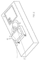
- FIG. 2 is an expanded perspective view illustrating the armrest assembly of FIG. 1 with an arm support member in a position to support a user's palm;
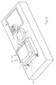
- FIG. 3 is a perspective view illustrating the armrest assembly of FIG. 2 with the arm support member in a position to support a user's wrist/forearm;
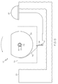
- FIG. 4 is a schematic side view illustrating various features of the armrest assembly of FIG. 1 with the arm support member in a position to support a user's palm;
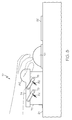
- FIG. 5 is a cutaway, schematic side view illustrating the armrest assembly of FIG. 4 with the arm support member in a position to support a user's wrist/forearm;
- FIG. 6 is a schematic side view of an alternate embodiment of an armrest assembly with the arm support member in a position that supports a user's arm proximate a first control device;
- FIG. 7 is a schematic side view of the armrest assembly of FIG. 6 with the arm support member in a position that supports a user's arm proximate a second control device;
- FIG. 8 is a schematic side view of an alternate embodiment of an armrest assembly with the arm support member in a position that supports a user's arm proximate a first control device;
- FIG. 9 is a schematic side view of the armrest assembly of FIG. 8 with the arm support member in a position that supports a user's arm proximate a second control device;
- FIG. 10 is a perspective view illustrating an alternate embodiment of an armrest assembly with the arm support member in a position to support a user's palm;
- FIG. 11 is a perspective view illustrating the armrest assembly of FIG. 10 with the arm support member in a position to support a user's wrist/forearm;
- FIG. 12 is cutaway a schematic side view illustrating various features of the armrest assembly of FIG. 10 with the arm support member in a position to support a user's palm;
- FIG. 13 is a cutaway schematic side view illustrating the armrest assembly of FIG. 12 with the arm support member in a position to support a user's wrist/forearm.
- An improved armrest assembly is disclosed herein that is adapted to support a user's arm against unintended movement caused by motion of a vehicle as the user accesses two control devices arranged in tandem.
- the armrest assembly is longitudinally aligned with the two control devices and includes a base and an arm support member that is movably mounted on the base.
- the arm support member moves between a first position and a second position. While in the first position, the arm support member is configured to support a user's arm as the user manipulates the control device located closest to the armrest assembly. While in the second position, the arm support member is configured to support the user's arm as the user manipulates the control device located remotely from the arm support member.
- FIG. 1 is a perspective view illustrating an aircraft flight deck 20 including an embodiment of an armrest assembly 22 made in accordance with the teachings of the present disclosure. While the context of this discussion is that of an aircraft, it should be understood that armrest assembly 22 is not limited to use with aircraft. Rather, armrest assembly 22 is compatible with any type of vehicle including spacecraft, watercraft, and vehicles adapted to travel over land. Although the drawings illustrate the center console in an aircraft, the armrest can be located in any location in the aircraft that supports the access to the control devices.
- Armrest assembly 22 is mounted to a center pedestal 24, which is positioned between a pilot seat 26 and a co-pilot seat 28.
- a first control device 30 and a second control device 32 are mounted to center pedestal 24 where they are each accessible to both a pilot and a co-pilot.
- first control device 30 is a track ball that may be used to control a cursor on a flight display 34
- second control device 32 is a touch screen control panel that may be used to control various functions of the aircraft.
- first and second control devices 30 and 32 may both be touch screen control panels or may both be track balls, or each may be any of a wide variety of other types of control devices including, but not limited to, touch pads, key boards, knobs, switches, buttons, and dials.
- First and second control devices 30 and 32 are arranged in tandem on center pedestal 24, with second control device 32 being positioned forward of first control device 30.
- Armrest assembly 22 is located rearward of first control device 30 and is generally longitudinally aligned with both first control device 30 and second control devices 32.
- the terms "forward” and "rearward”, as used herein, are with reference to the direction of vehicle travel.
- a pilot or co-pilot can rest their hand or a portion of their arm on armrest assembly 22 to stabilize their hand with respect to center pedestal 24. Additionally, as discussed in detail below, a portion of armrest assembly 22 is configured to move as the pilot or co-pilot moves their hand between first and second control devices 30 and 32.
- armrest assembly 22 can provide continuous stabilizing support to a hand or arm, and thereby make it less likely that any inadvertent control inputs will be input into either first control device 30 or second control device 32 as the pilot or co-pilot manipulates these control devices.
- FIG. 2 is an expanded perspective view illustrating the armrest assembly 22 of FIG. 1 .
- Armrest assembly 22 includes a base member 36 and an arm support member 38.
- Arm support member 38 is rotatably mounted to base member 36 and is configured to rotate between a first position (shown in FIG. 2 ) and a second position (shown in FIG. 3 ).
- first position shown in FIG. 2
- second position shown in FIG. 3
- alternate embodiments configured to permit other types of movement of arm support member 38 are contemplated by this disclosure.
- arm support member 38 While in the first position, arm support member 38 presents a surface 40 having a generally convex contour. This configuration is well suited for receiving the palm of a person's hand, as illustrated by the hand and arm portion drawn in phantom lines. With a person's palm resting on the convex surface of arm support member 38, the person's fingers can easily access and manipulate first control device 30.
- FIG. 3 is a perspective view illustrating armrest assembly 22 with arm support member 38 in a position to support a user's wrist/forearm.
- arm support member 38 has rotated to the second position, exposing a surface 42 having a generally concave contour.
- the shallow portion of surface 42 is aligned with first and second control devices 30 and 32, making it well suited for a person to rest either their wrist or a portion of their forearm on surface 42.
- the person's arm is stabilized with respect to center pedestal 24 and their fingers are positioned in close proximity to second control device 32 as illustrated by the hand and arm portion drawn in phantom lines.
- FIGS. 2 and 3 include a convex surface (surface 40) and a concave surface (surface 42), it should be understood that other geometric configurations, including, but not limited to, flat configurations may also be employed.
- FIG. 4 is a schematic side view illustrating various features of armrest assembly 22 with arm support member 38 in a position to support a user's palm.
- Arm support member 38 is generally configured as a wheel with surfaces 40 and 42 spaced apart from one another at a periphery of arm support member 38.
- the circumferential distance between surface 40 and surface 42 will vary to correspond with the longitudinal distance between first and second control devices 30 and 32.
- arm support member 38 may not be configured as a wheel, but may instead have different geometric configurations.
- Arm support member 38 is mounted to base member 36 via a pin 44 extending through arm support member 38 and about which arm support member 38 rotates.
- alternate configurations suitable for providing a rotational relationship between base member 36 and arm support member 38 may be employed without departing from the teachings of the present disclosure.
- Armrest assembly 22 further includes a torsion spring 46 connected at a first end 48 to base member 36 and at a second end 50 to arm support member 38.
- torsion spring 46 stores energy.
- torsion spring 46 releases its energy and causes arm support member 38 to rotate in a counter-clockwise direction (from the perspective of FIG. 4 ) back to the first position where surface 40 is exposed.
- suitable stopping members may be included in armrest assembly 22 to prevent rotation of arm support member 38 beyond predetermined limits in either the clockwise or counter-clockwise direction.
- armrest assembly 22 also includes an interlock mechanism 52 which can prevent first control device 30 from responding to any inputs while arm support member 38 is in the second position.
- interlock mechanism 52 comprises a cable extending from a lower portion 54 of arm support member 38 to a switch 56.
- Switch 56 is electrically interposed in a wire 58 that delivers power to first control device 30.
- Switch 56 is urged by a torsion spring 60 towards a closed position.
- interlock mechanism 52 will pull on and open switch 56, thus stopping the flow of power to first control device 30 and rendering first control device 30 inoperative.
- the interlock may activate a control signal that notifies the control surface to ignore all touches. This control signal can go directly to the control device or via any system that has access to the control device.
- the interlock switch may be any device including a mechanical switch, a proximity sensor, an optical sensor, optical encoder, or any device that indicates the position of the arm rest.
- FIG. 5 is a schematic side view illustrating armrest assembly 22 of FIG. 4 with the arm support member 38 in a position to support a user's wrist/forearm.
- arm support member 38 is in position two, and interlock mechanism 52 has opened switch 56, thereby depriving first control device 30 of power.
- Torsion spring 46 and torsion spring 60 are each storing energy. Torsion spring 46 is urging arm support member 38 towards the first position (i.e., in the direction of arrow 61) and torsion spring 60 is urging switch 56 towards the closed position.
- the urging of torsion spring 46 will cause arm support member 38 to return to the first position.
- interlock mechanism 52 will slacken and torsion spring 60 will cause switch 56 to close, thus restoring power to first control device 30.
- FIG. 6 is a schematic side view of an alternate embodiment of an armrest assembly 62 with an arm support member 64 in a position that supports a user's arm proximate first control device 30.
- Armrest assembly 62 includes a base member 66 mounted to center pedestal 24.
- Arm support member 64 is telescopically mounted to base member 66 and is configured to move longitudinally between a first position and a second position.
- arm support member 64 includes a convex portion 68 having a convex contour which is configured to accommodate the palm of a person's hand. While in the first position, which is illustrated in FIG. 6 , when a person rests the palm of their hand on convex portion 68, their fingers are disposed proximate first control device 30.
- Armrest assembly 62 further includes a spring 70 connecting arm support member 64 to base member 66.
- FIG. 7 is a schematic side view of armrest assembly 62 with arm support member 64 in a position that supports a person's arm proximate second control device 32.
- arm support member 64 When arm support member 64 is in the second position (as illustrated in FIG. 7 ) the user's fingers will be positioned to provide inputs into second control device 32.
- Spring 70 has been stretched and now stores energy.
- arm support member 64 When the person lifts their arm from arm support member 64, arm support member 64 will retract within base member 66 (i.e., return to the first position).
- an interlock mechanism may be fitted to armrest assembly 62.
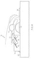
- FIG. 8 is a schematic side view of an alternate embodiment of an armrest assembly 72 with an arm support member 74 in a position that supports a user's arm proximate first control device 30.
- Arm support member 74 includes a convex portion 80 having a convex contour which is configured to accommodate the palm of a person's hand. While in the first position, which is illustrated in FIG. 8 , when a person rests the palm of their hand on convex portion 80, their fingers are disposed proximate first control device 30.
- Arm support member 74 is connected to a base member 76 via a four bar linkage 78.
- Two bars of four bar linkage 78 are visible in FIG. 8 and it should be understood that two additional bars link the opposite side of arm support member 74 to the opposite side of base member 76.
- Four bar linkage 78 permits movement of arm support member 74 in a longitudinal direction towards second control device 32.
- Springs 82 are connected to four bar linkage 78 in a manner that biases arm support member 74 towards the first position.
- FIG. 9 is a schematic side view of armrest assembly 72 with arm support member 74 in a position that supports a user's arm proximate second control device 32.
- arm support member 74 When arm support member 74 is in the second position (as illustrated in FIG. 9 ) the user's fingers will be positioned to provide inputs into second control device 32. Springs 82 have been stretched and now store energy. When the person lifts their arm from arm support member 74, arm support member 74 will return to the first position.
- an interlock mechanism may be fitted to armrest assembly 72.
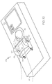
- FIG. 10 is a perspective view illustrating an alternate embodiment of an armrest assembly 84 with the arm support member 86 in a position to support a user's palm.
- Arm support member 86 is movably mounted to a base member 88 via a two bar linkage 90. Further, arm support member 86 is rotatably mounted to two bar linkage 90. Accordingly, arm support member 86 can move longitudinally with respect to base member 88 between a first position (shown in FIG. 10 ) and a second position (shown in FIG. 11 ) and can also rotate with respect to two bar linkage 90.
- a generally convex surface faces upward and is contoured to conform to the palm of a person's hand, as illustrated in phantom lines.
- arm support member 86 When arm support member 86 is in the first position, a person's fingers will be disposed in close proximity to first control device 30, thus facilitating the pilot or co-pilot's ability to stably manipulate first control device 30.
- Springs 92 join two bar linkage 90 to base member 88 and bias arm support member 86 towards the first position.
- arm support member 86 will both move forward and rotate in a clockwise direction (from the perspective of FIG. 10 ) and springs 92 will store energy.
- a surface of arm support member 86 that faces downward in FIG. 11 will rotate into an upward facing position to support the person's arm.
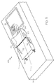
- FIG. 11 is a perspective view illustrating armrest assembly 84 with arm support member 86 in a position to support a user's wrist/forearm.
- arm support member 86 is shown in the second position where it has moved longitudinally forward, toward second control device 32, and has also rotated such that its generally convex surface (shown in FIG. 10 ) faces downward and a concave surface now faces upward.
- the concave surface is contoured such that its shallow portion is longitudinally aligned with first and second control devices 30 and 32. In this manner, arm support member 86 is well suited for supporting a person's wrist or forearm when in the second position.
- arm support member 86 when arm support member 86 is in the second position, it is longitudinally closer to second control device 32 than it is when in the first position. Because arm support member 86 moves longitudinally towards second control device 32, armrest assembly 84 is well suited for supporting a person's arm in a configuration of center pedestal 24 where first and second control devices 30 and 32 are not disposed in close proximity to one another.
- arm support member 86 When the person lifts their arm from armrest assembly 84, arm support member 86 will move back to the first position under the urging of springs 92. Additionally, interference between a forward surface of base member 88 and a rearward surface of arm support member 86 may cause arm support member 86 to rotate such that its convex surface is once again facing upwards.
- one or more torsion springs may be attached to two bar linkage 90 that will store energy when the concave surface faces upwards and that will urge arm support member 86 to rotate back towards a position where its convex surface faces in an upward direction once the person lifts their arm from armrest assembly 84.
- FIG. 12 is a cutaway, schematic side view illustrating various features of armrest assembly 84 with arm support member 86 in a position to support a user's palm.
- Armrest assembly 84 includes an interlock mechanism 94.
- interlock mechanism 94 comprises a cable attached at one end to a switch 96 and at an opposite end to two bar linkage 90.
- Switch 96 is interposed in electrical wire 98 which delivers power to first control device 30.
- a torsion spring 100 biases switch 96 towards a close state. While arm support member 86 is in the first position, switch 96 stays closed and power flows to first control device 30.
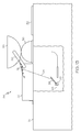
- FIG. 13 is a cutaway schematic side view illustrating armrest assembly 84 with arm support member 86 in a position to support a user's wrist/forearm.
- interlock mechanism 94 pulls switch 96 open, preventing the flow of electricity through electrical wire 98 and thus depriving first control device 30 of power. This prevents any inadvertent contact with first control device 30 from resulting in any inadvertent control inputs being input into a system controlled by first control device 30.
- first control device 30 may serve to support arm support member 86 while it is the second position.
- springs 92 stores energy torsion and urges arm support member 86 back towards the first position.
- torsion spring 100 stores energy and urges switch 96 back towards a closed state.
Landscapes
- Physics & Mathematics (AREA)
- General Physics & Mathematics (AREA)
- Engineering & Computer Science (AREA)
- Automation & Control Theory (AREA)
- Mechanical Control Devices (AREA)
- Chair Legs, Seat Parts, And Backrests (AREA)
Abstract
Description
- The present invention generally relates to armrest assemblies, and more particularly relates to armrest assemblies for use with a first control device and a second control device arranged in tandem.
- Control devices including, but not limited to, touch screens, keyboards, and cursor control devices (e.g., track balls) are used in the operation and control of vehicles. Such control devices are commonly used, for instance, in aircraft, spacecraft, water craft and automobiles. These control devices are frequently mounted on horizontal surfaces. For instance, the center pedestal located between a pilot and a co-pilot may include such control devices. In many instances, two or more control devices are arranged on the center pedestal or other surfaces within the flight deck and are arranged in tandem or are otherwise longitudinally aligned.
- During vehicle operations, the vehicle frequently encounters disruptive motion of some sort. For example, an aircraft may encounter turbulence, a water craft may bounce from wave to wave, an automobile may encounter pot holes, speed bumps, etc.... Under such circumstances, vehicle operators may have difficulty in keeping their hands steady as they attempt to use the control devices. This can result in the typing of an incorrect letter on a keyboard, the selection of an undesired menu option with a cursor control device, or the touching of an undesired graphic button using a touch screen.
- One solution has been to provide a raised surface proximate the control device on which vehicle operators may rest their hands. This allows vehicle operators to keep their hands substantially steady and immobile with respect to the control device that they are manipulating. This solution is adequate when vehicle operators are presented with a single control device, but when there are two or more such control devices aligned longitudinally, the raised surface may be adequate only for the proximate control device. The vehicle operator will still have to manipulate the distal control devices with an unsupported hand.
- An armrest assembly for use with a first control device and a second control device arranged in a generally in tandem configuration is disclosed herein.
- In a first embodiment, the armrest assembly includes, but is not limited to, a base member that is configured for mounting to a surface proximate the first control device in a position that is generally longitudinally aligned with the first control device and the second control device, and an arm support member that is movably mounted to the base member. The arm support member is configured to move between a first position and a second position. The arm support member is configured to steady a user's arm while accessing the first control device when the arm support member is in the first position. The arm support member is further configured to steady the user's arm while accessing the second control device when the arm support member is in the second position.
- In a second embodiment, the armrest assembly includes, but is not limited to, a base member that is configured for mounting to a surface proximate the first control device in a position that is generally longitudinally aligned with the first control device and the second control device, and an arm support member that is rotatably mounted to the base member. The arm support member is configured to rotate between a first position and a second position. The arm support member is configured to steady a user's arm when accessing the first control device when the arm support member is in the first position,. The arm support member is further configured to steady the user's arm when accessing the second control device when the arm support member is in the second position.
- In a third embodiment, the armrest assembly includes, but is not limited to, a base member that is configured for mounting to a surface proximate the first control device in a position that is generally longitudinally aligned with the first control device and the second control device, and an arm support member that is mounted to the base member via a two bar linkage and configured to articulate between a first position and a second position. The arm support member is configured to steady a user's arm when accessing the first control device when the arm support member is in the first position. The arm support member is further configured to steady the user's arm when accessing the second control device when the arm support member is in the second position.
- The present invention will hereinafter be described in conjunction with the following drawing figures, wherein like numerals denote like elements, and
-
FIG. 1 is a perspective view illustrating an aircraft flight deck including an embodiment of an armrest assembly made in accordance with the teachings of the present disclosure; -
FIG. 2 is an expanded perspective view illustrating the armrest assembly ofFIG. 1 with an arm support member in a position to support a user's palm; -
FIG. 3 is a perspective view illustrating the armrest assembly ofFIG. 2 with the arm support member in a position to support a user's wrist/forearm; -
FIG. 4 is a schematic side view illustrating various features of the armrest assembly ofFIG. 1 with the arm support member in a position to support a user's palm; -
FIG. 5 is a cutaway, schematic side view illustrating the armrest assembly ofFIG. 4 with the arm support member in a position to support a user's wrist/forearm; -
FIG. 6 . is a schematic side view of an alternate embodiment of an armrest assembly with the arm support member in a position that supports a user's arm proximate a first control device; -
FIG. 7 is a schematic side view of the armrest assembly ofFIG. 6 with the arm support member in a position that supports a user's arm proximate a second control device; -
FIG. 8 . is a schematic side view of an alternate embodiment of an armrest assembly with the arm support member in a position that supports a user's arm proximate a first control device; -
FIG. 9 is a schematic side view of the armrest assembly ofFIG. 8 with the arm support member in a position that supports a user's arm proximate a second control device; -
FIG. 10 is a perspective view illustrating an alternate embodiment of an armrest assembly with the arm support member in a position to support a user's palm; -
FIG. 11 is a perspective view illustrating the armrest assembly ofFIG. 10 with the arm support member in a position to support a user's wrist/forearm; -
FIG. 12 is cutaway a schematic side view illustrating various features of the armrest assembly ofFIG. 10 with the arm support member in a position to support a user's palm; and -
FIG. 13 is a cutaway schematic side view illustrating the armrest assembly ofFIG. 12 with the arm support member in a position to support a user's wrist/forearm. - The following detailed description is merely exemplary in nature and is not intended to limit the invention or the application and uses of the invention. Furthermore, there is no intention to be bound by any theory presented in the preceding background or the following detailed description.
- An improved armrest assembly is disclosed herein that is adapted to support a user's arm against unintended movement caused by motion of a vehicle as the user accesses two control devices arranged in tandem. The armrest assembly is longitudinally aligned with the two control devices and includes a base and an arm support member that is movably mounted on the base. The arm support member moves between a first position and a second position. While in the first position, the arm support member is configured to support a user's arm as the user manipulates the control device located closest to the armrest assembly. While in the second position, the arm support member is configured to support the user's arm as the user manipulates the control device located remotely from the arm support member.
- A further understanding of the armrest assembly disclosed herein may be obtained through a review of the illustrations accompanying this application together with a review of the detailed description that follows.
-
FIG. 1 is a perspective view illustrating anaircraft flight deck 20 including an embodiment of anarmrest assembly 22 made in accordance with the teachings of the present disclosure. While the context of this discussion is that of an aircraft, it should be understood thatarmrest assembly 22 is not limited to use with aircraft. Rather,armrest assembly 22 is compatible with any type of vehicle including spacecraft, watercraft, and vehicles adapted to travel over land. Although the drawings illustrate the center console in an aircraft, the armrest can be located in any location in the aircraft that supports the access to the control devices. -
Armrest assembly 22 is mounted to acenter pedestal 24, which is positioned between apilot seat 26 and aco-pilot seat 28. Afirst control device 30 and asecond control device 32 are mounted tocenter pedestal 24 where they are each accessible to both a pilot and a co-pilot. InFIG. 1 ,first control device 30 is a track ball that may be used to control a cursor on aflight display 34 andsecond control device 32 is a touch screen control panel that may be used to control various functions of the aircraft. In other embodiments, first andsecond control devices - First and
second control devices center pedestal 24, withsecond control device 32 being positioned forward offirst control device 30.Armrest assembly 22 is located rearward offirst control device 30 and is generally longitudinally aligned with bothfirst control device 30 andsecond control devices 32. The terms "forward" and "rearward", as used herein, are with reference to the direction of vehicle travel. A pilot or co-pilot can rest their hand or a portion of their arm onarmrest assembly 22 to stabilize their hand with respect tocenter pedestal 24. Additionally, as discussed in detail below, a portion ofarmrest assembly 22 is configured to move as the pilot or co-pilot moves their hand between first andsecond control devices armrest assembly 22 can provide continuous stabilizing support to a hand or arm, and thereby make it less likely that any inadvertent control inputs will be input into eitherfirst control device 30 orsecond control device 32 as the pilot or co-pilot manipulates these control devices. -
FIG. 2 is an expanded perspective view illustrating thearmrest assembly 22 ofFIG. 1 .Armrest assembly 22 includes abase member 36 and anarm support member 38.Arm support member 38 is rotatably mounted tobase member 36 and is configured to rotate between a first position (shown inFIG. 2 ) and a second position (shown inFIG. 3 ). As discussed below, alternate embodiments configured to permit other types of movement ofarm support member 38 are contemplated by this disclosure. - While in the first position,
arm support member 38 presents asurface 40 having a generally convex contour. This configuration is well suited for receiving the palm of a person's hand, as illustrated by the hand and arm portion drawn in phantom lines. With a person's palm resting on the convex surface ofarm support member 38, the person's fingers can easily access and manipulatefirst control device 30. -
FIG. 3 is a perspective view illustratingarmrest assembly 22 witharm support member 38 in a position to support a user's wrist/forearm. InFIG. 3 ,arm support member 38 has rotated to the second position, exposing asurface 42 having a generally concave contour. The shallow portion ofsurface 42 is aligned with first andsecond control devices surface 42. With a person's wrist/forearm resting onsurface 42, the person's arm is stabilized with respect tocenter pedestal 24 and their fingers are positioned in close proximity tosecond control device 32 as illustrated by the hand and arm portion drawn in phantom lines. Although the embodiment illustrated inFIGS. 2 and3 include a convex surface (surface 40) and a concave surface (surface 42), it should be understood that other geometric configurations, including, but not limited to, flat configurations may also be employed. -
FIG. 4 is a schematic side view illustrating various features ofarmrest assembly 22 witharm support member 38 in a position to support a user's palm. In the illustrated embodiment,Arm support member 38 is generally configured as a wheel withsurfaces arm support member 38. In differing embodiments, the circumferential distance betweensurface 40 andsurface 42 will vary to correspond with the longitudinal distance between first andsecond control devices arm support member 38 may not be configured as a wheel, but may instead have different geometric configurations. -
Arm support member 38 is mounted tobase member 36 via apin 44 extending througharm support member 38 and about whicharm support member 38 rotates. In other embodiments, alternate configurations suitable for providing a rotational relationship betweenbase member 36 andarm support member 38 may be employed without departing from the teachings of the present disclosure. With a person's palm resting onsurface 40, the person need only move their arm forward while maintaining contact witharm support member 38 andarm support member 38 will rotate in a clockwise direction (from the perspective ofFIG. 4 ), thus exposingsurface 42 which aligns with and cradles the person's wrist or forearm, depending upon the dimensions of the person's arm. -
Armrest assembly 22 further includes atorsion spring 46 connected at afirst end 48 tobase member 36 and at asecond end 50 toarm support member 38. As a person moves their arm forward (i.e., in the direction indicated by arrow 51) andarm support member 38 rotates to exposesurface 42,torsion spring 46 stores energy. When the person's arm is lifted fromarm support member 38,torsion spring 46 releases its energy and causesarm support member 38 to rotate in a counter-clockwise direction (from the perspective ofFIG. 4 ) back to the first position wheresurface 40 is exposed. In some embodiments, suitable stopping members may be included inarmrest assembly 22 to prevent rotation ofarm support member 38 beyond predetermined limits in either the clockwise or counter-clockwise direction. - In the embodiment illustrated in
FIG. 4 , and with continuing reference toFIGS. 1-3 ,armrest assembly 22 also includes aninterlock mechanism 52 which can preventfirst control device 30 from responding to any inputs whilearm support member 38 is in the second position. In the illustrated embodiment,interlock mechanism 52 comprises a cable extending from alower portion 54 ofarm support member 38 to aswitch 56.Switch 56 is electrically interposed in awire 58 that delivers power tofirst control device 30.Switch 56 is urged by atorsion spring 60 towards a closed position. Asarm support member 38 moves to the second position,interlock mechanism 52 will pull on andopen switch 56, thus stopping the flow of power tofirst control device 30 and renderingfirst control device 30 inoperative. This will preventfirst control device 30 from responding to any unintended control inputs in the event that there is inadvertent contact withfirst control device 30 while a person is accessingsecond control device 32. In other embodiments, other types of interlock mechanisms are also possible. For example, rather than controlling power as illustrated in these embodiments, the interlock may activate a control signal that notifies the control surface to ignore all touches. This control signal can go directly to the control device or via any system that has access to the control device. Also, the interlock switch may be any device including a mechanical switch, a proximity sensor, an optical sensor, optical encoder, or any device that indicates the position of the arm rest. -
FIG. 5 is a schematic side view illustratingarmrest assembly 22 ofFIG. 4 with thearm support member 38 in a position to support a user's wrist/forearm. As illustrated here,arm support member 38 is in position two, andinterlock mechanism 52 has openedswitch 56, thereby deprivingfirst control device 30 of power.Torsion spring 46 andtorsion spring 60 are each storing energy.Torsion spring 46 is urgingarm support member 38 towards the first position (i.e., in the direction of arrow 61) andtorsion spring 60 is urgingswitch 56 towards the closed position. When the person lifts their arm off ofarm support member 38, the urging oftorsion spring 46 will causearm support member 38 to return to the first position. Asarm support member 38 returns to the first position,interlock mechanism 52 will slacken andtorsion spring 60 will causeswitch 56 to close, thus restoring power tofirst control device 30. -
FIG. 6 . is a schematic side view of an alternate embodiment of anarmrest assembly 62 with anarm support member 64 in a position that supports a user's arm proximatefirst control device 30.Armrest assembly 62 includes abase member 66 mounted to centerpedestal 24.Arm support member 64 is telescopically mounted tobase member 66 and is configured to move longitudinally between a first position and a second position. As illustrated inFIG. 6 ,arm support member 64 includes aconvex portion 68 having a convex contour which is configured to accommodate the palm of a person's hand. While in the first position, which is illustrated inFIG. 6 , when a person rests the palm of their hand onconvex portion 68, their fingers are disposed proximatefirst control device 30.Armrest assembly 62 further includes aspring 70 connectingarm support member 64 tobase member 66. -
FIG. 7 is a schematic side view ofarmrest assembly 62 witharm support member 64 in a position that supports a person's arm proximatesecond control device 32. Whenarm support member 64 is in the second position (as illustrated inFIG. 7 ) the user's fingers will be positioned to provide inputs intosecond control device 32.Spring 70 has been stretched and now stores energy. When the person lifts their arm fromarm support member 64,arm support member 64 will retract within base member 66 (i.e., return to the first position). Although not illustrated, it should be understood that an interlock mechanism may be fitted toarmrest assembly 62. -
FIG. 8 . is a schematic side view of an alternate embodiment of anarmrest assembly 72 with anarm support member 74 in a position that supports a user's arm proximatefirst control device 30.Arm support member 74 includes aconvex portion 80 having a convex contour which is configured to accommodate the palm of a person's hand. While in the first position, which is illustrated inFIG. 8 , when a person rests the palm of their hand onconvex portion 80, their fingers are disposed proximatefirst control device 30. -
Arm support member 74 is connected to abase member 76 via a fourbar linkage 78. Two bars of fourbar linkage 78 are visible inFIG. 8 and it should be understood that two additional bars link the opposite side ofarm support member 74 to the opposite side ofbase member 76. Fourbar linkage 78 permits movement ofarm support member 74 in a longitudinal direction towardssecond control device 32.Springs 82 are connected to fourbar linkage 78 in a manner that biases armsupport member 74 towards the first position. -
FIG. 9 is a schematic side view ofarmrest assembly 72 witharm support member 74 in a position that supports a user's arm proximatesecond control device 32. Whenarm support member 74 is in the second position (as illustrated inFIG. 9 ) the user's fingers will be positioned to provide inputs intosecond control device 32.Springs 82 have been stretched and now store energy. When the person lifts their arm fromarm support member 74,arm support member 74 will return to the first position. Although not illustrated, it should be understood that an interlock mechanism may be fitted toarmrest assembly 72. -
FIG. 10 is a perspective view illustrating an alternate embodiment of anarmrest assembly 84 with thearm support member 86 in a position to support a user's palm.Arm support member 86 is movably mounted to abase member 88 via a twobar linkage 90. Further,arm support member 86 is rotatably mounted to twobar linkage 90. Accordingly,arm support member 86 can move longitudinally with respect tobase member 88 between a first position (shown inFIG. 10 ) and a second position (shown inFIG. 11 ) and can also rotate with respect to twobar linkage 90. When in the first position, a generally convex surface faces upward and is contoured to conform to the palm of a person's hand, as illustrated in phantom lines. Whenarm support member 86 is in the first position, a person's fingers will be disposed in close proximity tofirst control device 30, thus facilitating the pilot or co-pilot's ability to stably manipulatefirst control device 30. -
Springs 92 join twobar linkage 90 tobase member 88 and biasarm support member 86 towards the first position. As a person moves their arm towardssecond control device 32 while maintaining contact witharm support member 86,arm support member 86 will both move forward and rotate in a clockwise direction (from the perspective ofFIG. 10 ) and springs 92 will store energy. Asarm support member 86 rotates, a surface ofarm support member 86 that faces downward inFIG. 11 will rotate into an upward facing position to support the person's arm. -
FIG. 11 is a perspective view illustratingarmrest assembly 84 witharm support member 86 in a position to support a user's wrist/forearm. Here,arm support member 86 is shown in the second position where it has moved longitudinally forward, towardsecond control device 32, and has also rotated such that its generally convex surface (shown inFIG. 10 ) faces downward and a concave surface now faces upward. The concave surface is contoured such that its shallow portion is longitudinally aligned with first andsecond control devices arm support member 86 is well suited for supporting a person's wrist or forearm when in the second position. Furthermore, whenarm support member 86 is in the second position, it is longitudinally closer tosecond control device 32 than it is when in the first position. Becausearm support member 86 moves longitudinally towardssecond control device 32,armrest assembly 84 is well suited for supporting a person's arm in a configuration ofcenter pedestal 24 where first andsecond control devices - When the person lifts their arm from
armrest assembly 84,arm support member 86 will move back to the first position under the urging ofsprings 92. Additionally, interference between a forward surface ofbase member 88 and a rearward surface ofarm support member 86 may causearm support member 86 to rotate such that its convex surface is once again facing upwards. In other embodiments, one or more torsion springs may be attached to twobar linkage 90 that will store energy when the concave surface faces upwards and that will urgearm support member 86 to rotate back towards a position where its convex surface faces in an upward direction once the person lifts their arm fromarmrest assembly 84. -
FIG. 12 is a cutaway, schematic side view illustrating various features ofarmrest assembly 84 witharm support member 86 in a position to support a user's palm.Armrest assembly 84 includes aninterlock mechanism 94. In the illustrated embodiment,interlock mechanism 94 comprises a cable attached at one end to aswitch 96 and at an opposite end to twobar linkage 90.Switch 96 is interposed inelectrical wire 98 which delivers power tofirst control device 30. Atorsion spring 100 biases switch 96 towards a close state. Whilearm support member 86 is in the first position, switch 96 stays closed and power flows tofirst control device 30. -
FIG. 13 is a cutaway schematic side view illustratingarmrest assembly 84 witharm support member 86 in a position to support a user's wrist/forearm. Whenarm support member 86 is in the second position,interlock mechanism 94 pullsswitch 96 open, preventing the flow of electricity throughelectrical wire 98 and thus deprivingfirst control device 30 of power. This prevents any inadvertent contact withfirst control device 30 from resulting in any inadvertent control inputs being input into a system controlled byfirst control device 30. - In embodiments equipped with
interlock mechanism 94, such the one illustrated inFIG. 13 ,first control device 30 may serve to supportarm support member 86 while it is the second position. Whenarm support member 86 is disposed in the second position, springs 92 stores energy torsion and urgesarm support member 86 back towards the first position. Additionally, whenarm support member 86 is disposed in the second position,torsion spring 100 stores energy and urges switch 96 back towards a closed state. When the pilot or co-pilot lift their arm fromarmrest assembly 84,spring 92 will movearm support member 86 back to the first position andtorsion spring 100 will closeswitch 96, thus restoring the flow of electricity tofirst control device 30. - While at least one exemplary embodiment has been presented in the foregoing detailed description of the invention, it should be appreciated that a vast number of variations exist. It should also be appreciated that the exemplary embodiment or exemplary embodiments are only examples, and are not intended to limit the scope, applicability, or configuration of the invention in any way. Rather, the foregoing detailed description will provide those skilled in the art with a convenient road map for implementing an exemplary embodiment of the invention. It being understood that various changes may be made in the function and arrangement of elements described in an exemplary embodiment without departing from the scope of the invention as set forth in the appended claims.
Claims (10)
- An armrest assembly (22) for use with a first control device (30) and a second control device (32) arranged generally in a tandem configuration, the armrest assembly (22) comprising:a base member (36) configured for mounting to a surface (24) proximate the first control device (30) in a position generally longitudinally aligned with the first control (30) device and the second control device (32); andan arm support member (38) movably mounted to the base member (36), the arm support member (38) configured to move between a first position and a second position, the arm support member (38) configured to steady a user's arm while accessing the first control device (30) when the arm support member (38) is in the first position, and the arm support member (38) being further configured to steady the user's arm while accessing the second control device (32) when the arm support member (38) is in the second position.
- The armrest assembly (22) of claim 1, further comprising a biasing member (46) connected to the arm support member (38) and configured to bias the arm support member (38) towards the first position.
- The armrest assembly (22) of claim 1, further comprising an interlock mechanism (52) connected to the arm support member (38), the interlock mechanism (52) being configured to render the first control device (30) incapable of responding to control inputs while the arm support member (38) is in the second position.
- The armrest assembly (22) of claim 1, wherein the arm support member (38) is telescopically mounted to the base member (36).
- The armrest assembly (72) of claim 1, wherein the arm support member (74) is mounted to the base member (76) via a four bar linkage (78).
- An armrest assembly (22) for use with a first control device (30) and a second control device (32) arranged generally in a tandem configuration, the armrest assembly (22) comprising:a base member (36) configured for mounting to a surface (24) proximate the first control device (30) in a position aligned generally longitudinally with the first control device (30) and the second control device (32); andan arm support member (38) rotatably mounted to the base member (36), the arm support member (38) configured to rotate between a first position and a second position, the arm support member (38) configured to steady a user's arm while accessing the first control device (30) when the arm support member (38) is in the first position, and the arm support member (30) being further configured to steady the user's arm while accessing the second control device (32) when the arm support member (38) is in the second position.
- The armrest assembly (22) of claim 6, wherein the arm support member (38) has a first surface (40) and a second surface (42), wherein the first surface (40) is positioned on the arm support member (38) to support a first portion of the user's arm when the arm support member (30) is in the first position and wherein the second surface (42) is positioned on the arm support member (38) to support a second portion of the user's arm when the arm support member (38) is in the second position.
- The armrest assembly (22) of claim 7, wherein the first surface (40) is contoured in a manner that accommodates the first portion of the user's arm and wherein the second surface (42) is contoured in a manner that accommodates the second portion of the user's arm.
- The armrest assembly (22) of claim 8, wherein the first surface (40) has a generally convex configuration and wherein the second surface (42) has a generally concave configuration.
- An armrest assembly (84) for use with a first control device (30) and a second control device (32) arranged generally in a tandem configuration, the armrest assembly (84) comprising:a base member (88) configured for mounting to a surface (24) proximate the first control device (30) in a position generally longitudinally aligned with the first control device (30) and the second control device (32); andan arm support member (86) mounted to the base member (90) via a two bar linkage and configured to move between a first position and a second position, the arm support member (86) configured to steady a user's arm while accessing the first control device (30) when the arm support member (86) is in the first position, and the arm support member (86) being further configured to steady the user's arm while accessing the second control device (32) when the arm support member (86) is in the second position.
Applications Claiming Priority (1)
| Application Number | Priority Date | Filing Date | Title |
|---|---|---|---|
| US12/815,947 US8282051B2 (en) | 2010-06-15 | 2010-06-15 | Armrest assembly |
Publications (2)
| Publication Number | Publication Date |
|---|---|
| EP2397928A1 true EP2397928A1 (en) | 2011-12-21 |
| EP2397928B1 EP2397928B1 (en) | 2015-07-15 |
Family
ID=44720532
Family Applications (1)
| Application Number | Title | Priority Date | Filing Date |
|---|---|---|---|
| EP11169573.0A Active EP2397928B1 (en) | 2010-06-15 | 2011-06-10 | Armrest assembly |
Country Status (2)
| Country | Link |
|---|---|
| US (1) | US8282051B2 (en) |
| EP (1) | EP2397928B1 (en) |
Cited By (5)
| Publication number | Priority date | Publication date | Assignee | Title |
|---|---|---|---|---|
| GB2505413A (en) * | 2012-08-28 | 2014-03-05 | Ge Aviat Systems Ltd | An input device with a touch screen, track ball and palm rest |
| FR3034888A1 (en) * | 2015-04-07 | 2016-10-14 | Airbus Operations Sas | VEHICLE COMPRISING A TOUCH SCREEN |
| WO2018108433A1 (en) * | 2016-12-14 | 2018-06-21 | Lisa Dräxlmaier GmbH | Operating unit for a motor vehicle |
| WO2021156051A1 (en) * | 2020-02-04 | 2021-08-12 | Man Truck & Bus Se | Arrangement of a palm rest and an operating element for a vehicle |
| WO2022038383A1 (en) * | 2020-08-21 | 2022-02-24 | Hill Group Technologies Limited | Aircraft flight control |
Families Citing this family (12)
| Publication number | Priority date | Publication date | Assignee | Title |
|---|---|---|---|---|
| US9011515B2 (en) | 2012-04-19 | 2015-04-21 | Caisson Interventional, LLC | Heart valve assembly systems and methods |
| US9427315B2 (en) | 2012-04-19 | 2016-08-30 | Caisson Interventional, LLC | Valve replacement systems and methods |
| US9421094B2 (en) | 2013-10-23 | 2016-08-23 | Caisson Interventional, LLC | Methods and systems for heart valve therapy |
| JP6201864B2 (en) * | 2014-03-28 | 2017-09-27 | マツダ株式会社 | Vehicle control device |
| US9974647B2 (en) | 2014-06-12 | 2018-05-22 | Caisson Interventional, LLC | Two stage anchor and mitral valve assembly |
| US9750605B2 (en) | 2014-10-23 | 2017-09-05 | Caisson Interventional, LLC | Systems and methods for heart valve therapy |
| US9750607B2 (en) | 2014-10-23 | 2017-09-05 | Caisson Interventional, LLC | Systems and methods for heart valve therapy |
| EP3366637B1 (en) | 2015-01-29 | 2019-11-13 | Crown Equipment Corporation | Palm rest for a materials handling vehicle |
| EP3270827B1 (en) | 2015-03-19 | 2023-12-20 | Caisson Interventional, LLC | Systems for heart valve therapy |
| CA3010324A1 (en) | 2015-12-30 | 2017-07-06 | Caisson Interventional, LLC | Systems and methods for heart valve therapy |
| FR3122934B1 (en) * | 2021-05-17 | 2023-08-11 | Thales Sa | System for remote interaction with a pointing means of an aircraft cockpit display system. |
| FR3155927A1 (en) * | 2023-11-28 | 2025-05-30 | Thales | Remote interaction system with a pointing means of an HMI of an aircraft cockpit display system |
Citations (5)
| Publication number | Priority date | Publication date | Assignee | Title |
|---|---|---|---|---|
| US6056247A (en) * | 1997-10-14 | 2000-05-02 | Volvo Wheel Loaders Ab | Wrist support |
| EP1350669A2 (en) * | 2002-04-03 | 2003-10-08 | Kabushiki Kaisha Toyota Jidoshokki | Operating member and armrest for industrial vehicle |
| DE102006018537A1 (en) * | 2006-04-21 | 2007-11-08 | Grammer Ag | Control panel for use at arm rest of seat of e.g. tractor, has support element tiltable opposite to surface of panel for supporting hand, where pivotings of control lever and element partially surrounded within lower area are synchronized |
| DE102009008728A1 (en) * | 2009-02-12 | 2009-10-29 | Daimler Ag | Operating arrangement for central console of motor vehicle, comprises hand rest which is arranged above arm support, where hand rest comprises covering element which is moved from closing position to open position |
| DE102009008727A1 (en) * | 2009-02-12 | 2009-11-05 | Daimler Ag | Operating arrangement for center console of motor vehicle, has control panel partly covered in one position of partial element and is partly accessible in other position of partial element, where element slidingly moves between positions |
Family Cites Families (7)
| Publication number | Priority date | Publication date | Assignee | Title |
|---|---|---|---|---|
| US5201485A (en) * | 1990-07-10 | 1993-04-13 | Product Innovation, Inc. | Apparatus and method for reducing repetitive or maintained stress injuries |
| US6203109B1 (en) * | 1991-09-05 | 2001-03-20 | Industrial Ergonomics, Inc. | Ergonomic arm support |
| US5398896A (en) * | 1993-08-06 | 1995-03-21 | Terbrack; William H. | Dynamic support device for keyboards |
| US5383632A (en) * | 1993-08-20 | 1995-01-24 | Shirlin; Jack W. | Moveable forearm and wrist support |
| US6454224B1 (en) * | 2001-03-13 | 2002-09-24 | Dilip Nogueira | Forearm and wrist support assembly for keyboard user |
| KR100887807B1 (en) | 2007-10-15 | 2009-03-09 | 현대자동차주식회사 | The rear seat of the vehicle |
| US20090288123A1 (en) | 2008-05-14 | 2009-11-19 | Havlovick Ron G | Passenger tray convenience system |
-
2010
- 2010-06-15 US US12/815,947 patent/US8282051B2/en active Active
-
2011
- 2011-06-10 EP EP11169573.0A patent/EP2397928B1/en active Active
Patent Citations (5)
| Publication number | Priority date | Publication date | Assignee | Title |
|---|---|---|---|---|
| US6056247A (en) * | 1997-10-14 | 2000-05-02 | Volvo Wheel Loaders Ab | Wrist support |
| EP1350669A2 (en) * | 2002-04-03 | 2003-10-08 | Kabushiki Kaisha Toyota Jidoshokki | Operating member and armrest for industrial vehicle |
| DE102006018537A1 (en) * | 2006-04-21 | 2007-11-08 | Grammer Ag | Control panel for use at arm rest of seat of e.g. tractor, has support element tiltable opposite to surface of panel for supporting hand, where pivotings of control lever and element partially surrounded within lower area are synchronized |
| DE102009008728A1 (en) * | 2009-02-12 | 2009-10-29 | Daimler Ag | Operating arrangement for central console of motor vehicle, comprises hand rest which is arranged above arm support, where hand rest comprises covering element which is moved from closing position to open position |
| DE102009008727A1 (en) * | 2009-02-12 | 2009-11-05 | Daimler Ag | Operating arrangement for center console of motor vehicle, has control panel partly covered in one position of partial element and is partly accessible in other position of partial element, where element slidingly moves between positions |
Cited By (10)
| Publication number | Priority date | Publication date | Assignee | Title |
|---|---|---|---|---|
| GB2505413A (en) * | 2012-08-28 | 2014-03-05 | Ge Aviat Systems Ltd | An input device with a touch screen, track ball and palm rest |
| FR2995103A1 (en) * | 2012-08-28 | 2014-03-07 | Ge Aviat Systems Ltd | ENTRY DEVICE |
| FR3034888A1 (en) * | 2015-04-07 | 2016-10-14 | Airbus Operations Sas | VEHICLE COMPRISING A TOUCH SCREEN |
| WO2018108433A1 (en) * | 2016-12-14 | 2018-06-21 | Lisa Dräxlmaier GmbH | Operating unit for a motor vehicle |
| WO2021156051A1 (en) * | 2020-02-04 | 2021-08-12 | Man Truck & Bus Se | Arrangement of a palm rest and an operating element for a vehicle |
| US12083892B2 (en) | 2020-02-04 | 2024-09-10 | MAN Truck & Buse SE | Arrangement of a palm rest and an operating element for a vehicle |
| WO2022038383A1 (en) * | 2020-08-21 | 2022-02-24 | Hill Group Technologies Limited | Aircraft flight control |
| GB2602954A (en) * | 2020-08-21 | 2022-07-27 | Hill Group Tech Limited | Aircraft flight control |
| GB2602954B (en) * | 2020-08-21 | 2024-09-18 | Hill Group Tech Limited | Aircraft flight control |
| US12351332B2 (en) * | 2020-08-21 | 2025-07-08 | Hill Group Technologies Limited | Aircraft flight control |
Also Published As
| Publication number | Publication date |
|---|---|
| US20110303802A1 (en) | 2011-12-15 |
| EP2397928B1 (en) | 2015-07-15 |
| US8282051B2 (en) | 2012-10-09 |
Similar Documents
| Publication | Publication Date | Title |
|---|---|---|
| US8282051B2 (en) | Armrest assembly | |
| US5694123A (en) | Keyboard with integrated pointing device and click buttons with lock down for drag operation in a computer system with a graphical user interface | |
| US20190112030A1 (en) | Cockpit seat armrest avionics cursor control device | |
| JP2004245025A (en) | Control lever safety device for heavy equipment | |
| EP0515664A1 (en) | Laptop computer having integrated keyboard, cursor control device and palm rest | |
| US20080238874A1 (en) | Operation device | |
| US11682535B2 (en) | Rocker switch | |
| JP7256672B2 (en) | steering gear | |
| US20220396368A1 (en) | System for remote interaction with a pointing means of an aircraft cockpit display system | |
| JP4673695B2 (en) | Interface device | |
| CN101233016B (en) | Operation device for vehicle | |
| US20140310632A1 (en) | Mission system adapted for use in a strongly disturbed environment perturbed by movements of the carrier | |
| GB2516295A (en) | Keypad | |
| WO2019073538A1 (en) | Touch panel type display device | |
| EP3464781B1 (en) | Control center for an aerial device with control lever | |
| JP4157356B2 (en) | Joypad switch | |
| KR100918606B1 (en) | Car Manipulator | |
| CN204197302U (en) | Throttle console device | |
| SE520647C2 (en) | Hand control device for work vehicles | |
| EP2458608B1 (en) | Electric switch | |
| JP2002220197A (en) | Control lever safety device | |
| JP2000353022A (en) | Actuator | |
| US20070290987A1 (en) | Multifunctional mouse | |
| JP2010250860A (en) | Interface device | |
| JPH08221182A (en) | Keyboard integrated pointing device |
Legal Events
| Date | Code | Title | Description |
|---|---|---|---|
| 17P | Request for examination filed |
Effective date: 20110610 |
|
| AK | Designated contracting states |
Kind code of ref document: A1 Designated state(s): AL AT BE BG CH CY CZ DE DK EE ES FI FR GB GR HR HU IE IS IT LI LT LU LV MC MK MT NL NO PL PT RO RS SE SI SK SM TR |
|
| AX | Request for extension of the european patent |
Extension state: BA ME |
|
| PUAI | Public reference made under article 153(3) epc to a published international application that has entered the european phase |
Free format text: ORIGINAL CODE: 0009012 |
|
| 17Q | First examination report despatched |
Effective date: 20111206 |
|
| GRAP | Despatch of communication of intention to grant a patent |
Free format text: ORIGINAL CODE: EPIDOSNIGR1 |
|
| INTG | Intention to grant announced |
Effective date: 20150302 |
|
| GRAS | Grant fee paid |
Free format text: ORIGINAL CODE: EPIDOSNIGR3 |
|
| GRAA | (expected) grant |
Free format text: ORIGINAL CODE: 0009210 |
|
| AK | Designated contracting states |
Kind code of ref document: B1 Designated state(s): AL AT BE BG CH CY CZ DE DK EE ES FI FR GB GR HR HU IE IS IT LI LT LU LV MC MK MT NL NO PL PT RO RS SE SI SK SM TR |
|
| REG | Reference to a national code |
Ref country code: CH Ref legal event code: EP Ref country code: GB Ref legal event code: FG4D |
|
| REG | Reference to a national code |
Ref country code: IE Ref legal event code: FG4D |
|
| REG | Reference to a national code |
Ref country code: AT Ref legal event code: REF Ref document number: 737099 Country of ref document: AT Kind code of ref document: T Effective date: 20150815 |
|
| REG | Reference to a national code |
Ref country code: DE Ref legal event code: R096 Ref document number: 602011017826 Country of ref document: DE |
|
| REG | Reference to a national code |
Ref country code: AT Ref legal event code: MK05 Ref document number: 737099 Country of ref document: AT Kind code of ref document: T Effective date: 20150715 |
|
| RAP2 | Party data changed (patent owner data changed or rights of a patent transferred) |
Owner name: HONEYWELL INTERNATIONAL INC. |
|
| REG | Reference to a national code |
Ref country code: NL Ref legal event code: MP Effective date: 20150715 |
|
| REG | Reference to a national code |
Ref country code: LT Ref legal event code: MG4D |
|
| PG25 | Lapsed in a contracting state [announced via postgrant information from national office to epo] |
Ref country code: FI Free format text: LAPSE BECAUSE OF FAILURE TO SUBMIT A TRANSLATION OF THE DESCRIPTION OR TO PAY THE FEE WITHIN THE PRESCRIBED TIME-LIMIT Effective date: 20150715 Ref country code: LT Free format text: LAPSE BECAUSE OF FAILURE TO SUBMIT A TRANSLATION OF THE DESCRIPTION OR TO PAY THE FEE WITHIN THE PRESCRIBED TIME-LIMIT Effective date: 20150715 Ref country code: LV Free format text: LAPSE BECAUSE OF FAILURE TO SUBMIT A TRANSLATION OF THE DESCRIPTION OR TO PAY THE FEE WITHIN THE PRESCRIBED TIME-LIMIT Effective date: 20150715 Ref country code: NO Free format text: LAPSE BECAUSE OF FAILURE TO SUBMIT A TRANSLATION OF THE DESCRIPTION OR TO PAY THE FEE WITHIN THE PRESCRIBED TIME-LIMIT Effective date: 20151015 Ref country code: GR Free format text: LAPSE BECAUSE OF FAILURE TO SUBMIT A TRANSLATION OF THE DESCRIPTION OR TO PAY THE FEE WITHIN THE PRESCRIBED TIME-LIMIT Effective date: 20151016 |
|
| PG25 | Lapsed in a contracting state [announced via postgrant information from national office to epo] |
Ref country code: RS Free format text: LAPSE BECAUSE OF FAILURE TO SUBMIT A TRANSLATION OF THE DESCRIPTION OR TO PAY THE FEE WITHIN THE PRESCRIBED TIME-LIMIT Effective date: 20150715 Ref country code: PL Free format text: LAPSE BECAUSE OF FAILURE TO SUBMIT A TRANSLATION OF THE DESCRIPTION OR TO PAY THE FEE WITHIN THE PRESCRIBED TIME-LIMIT Effective date: 20150715 Ref country code: IS Free format text: LAPSE BECAUSE OF FAILURE TO SUBMIT A TRANSLATION OF THE DESCRIPTION OR TO PAY THE FEE WITHIN THE PRESCRIBED TIME-LIMIT Effective date: 20151115 Ref country code: AT Free format text: LAPSE BECAUSE OF FAILURE TO SUBMIT A TRANSLATION OF THE DESCRIPTION OR TO PAY THE FEE WITHIN THE PRESCRIBED TIME-LIMIT Effective date: 20150715 Ref country code: HR Free format text: LAPSE BECAUSE OF FAILURE TO SUBMIT A TRANSLATION OF THE DESCRIPTION OR TO PAY THE FEE WITHIN THE PRESCRIBED TIME-LIMIT Effective date: 20150715 Ref country code: PT Free format text: LAPSE BECAUSE OF FAILURE TO SUBMIT A TRANSLATION OF THE DESCRIPTION OR TO PAY THE FEE WITHIN THE PRESCRIBED TIME-LIMIT Effective date: 20151116 Ref country code: ES Free format text: LAPSE BECAUSE OF FAILURE TO SUBMIT A TRANSLATION OF THE DESCRIPTION OR TO PAY THE FEE WITHIN THE PRESCRIBED TIME-LIMIT Effective date: 20150715 Ref country code: SE Free format text: LAPSE BECAUSE OF FAILURE TO SUBMIT A TRANSLATION OF THE DESCRIPTION OR TO PAY THE FEE WITHIN THE PRESCRIBED TIME-LIMIT Effective date: 20150715 |
|
| REG | Reference to a national code |
Ref country code: DE Ref legal event code: R097 Ref document number: 602011017826 Country of ref document: DE |
|
| PG25 | Lapsed in a contracting state [announced via postgrant information from national office to epo] |
Ref country code: SK Free format text: LAPSE BECAUSE OF FAILURE TO SUBMIT A TRANSLATION OF THE DESCRIPTION OR TO PAY THE FEE WITHIN THE PRESCRIBED TIME-LIMIT Effective date: 20150715 Ref country code: CZ Free format text: LAPSE BECAUSE OF FAILURE TO SUBMIT A TRANSLATION OF THE DESCRIPTION OR TO PAY THE FEE WITHIN THE PRESCRIBED TIME-LIMIT Effective date: 20150715 Ref country code: EE Free format text: LAPSE BECAUSE OF FAILURE TO SUBMIT A TRANSLATION OF THE DESCRIPTION OR TO PAY THE FEE WITHIN THE PRESCRIBED TIME-LIMIT Effective date: 20150715 Ref country code: DK Free format text: LAPSE BECAUSE OF FAILURE TO SUBMIT A TRANSLATION OF THE DESCRIPTION OR TO PAY THE FEE WITHIN THE PRESCRIBED TIME-LIMIT Effective date: 20150715 Ref country code: IT Free format text: LAPSE BECAUSE OF FAILURE TO SUBMIT A TRANSLATION OF THE DESCRIPTION OR TO PAY THE FEE WITHIN THE PRESCRIBED TIME-LIMIT Effective date: 20150715 |
|
| PLBE | No opposition filed within time limit |
Free format text: ORIGINAL CODE: 0009261 |
|
| STAA | Information on the status of an ep patent application or granted ep patent |
Free format text: STATUS: NO OPPOSITION FILED WITHIN TIME LIMIT |
|
| PG25 | Lapsed in a contracting state [announced via postgrant information from national office to epo] |
Ref country code: RO Free format text: LAPSE BECAUSE OF FAILURE TO SUBMIT A TRANSLATION OF THE DESCRIPTION OR TO PAY THE FEE WITHIN THE PRESCRIBED TIME-LIMIT Effective date: 20150715 |
|
| REG | Reference to a national code |
Ref country code: FR Ref legal event code: PLFP Year of fee payment: 6 |
|
| 26N | No opposition filed |
Effective date: 20160418 |
|
| PG25 | Lapsed in a contracting state [announced via postgrant information from national office to epo] |
Ref country code: SI Free format text: LAPSE BECAUSE OF FAILURE TO SUBMIT A TRANSLATION OF THE DESCRIPTION OR TO PAY THE FEE WITHIN THE PRESCRIBED TIME-LIMIT Effective date: 20150715 |
|
| PG25 | Lapsed in a contracting state [announced via postgrant information from national office to epo] |
Ref country code: BE Free format text: LAPSE BECAUSE OF FAILURE TO SUBMIT A TRANSLATION OF THE DESCRIPTION OR TO PAY THE FEE WITHIN THE PRESCRIBED TIME-LIMIT Effective date: 20150715 |
|
| PG25 | Lapsed in a contracting state [announced via postgrant information from national office to epo] |
Ref country code: MC Free format text: LAPSE BECAUSE OF FAILURE TO SUBMIT A TRANSLATION OF THE DESCRIPTION OR TO PAY THE FEE WITHIN THE PRESCRIBED TIME-LIMIT Effective date: 20150715 |
|
| REG | Reference to a national code |
Ref country code: CH Ref legal event code: PL |
|
| GBPC | Gb: european patent ceased through non-payment of renewal fee |
Effective date: 20160610 |
|
| REG | Reference to a national code |
Ref country code: IE Ref legal event code: MM4A |
|
| PG25 | Lapsed in a contracting state [announced via postgrant information from national office to epo] |
Ref country code: CH Free format text: LAPSE BECAUSE OF NON-PAYMENT OF DUE FEES Effective date: 20160630 Ref country code: LI Free format text: LAPSE BECAUSE OF NON-PAYMENT OF DUE FEES Effective date: 20160630 |
|
| REG | Reference to a national code |
Ref country code: FR Ref legal event code: PLFP Year of fee payment: 7 |
|
| PG25 | Lapsed in a contracting state [announced via postgrant information from national office to epo] |
Ref country code: IE Free format text: LAPSE BECAUSE OF NON-PAYMENT OF DUE FEES Effective date: 20160610 Ref country code: GB Free format text: LAPSE BECAUSE OF NON-PAYMENT OF DUE FEES Effective date: 20160610 |
|
| PG25 | Lapsed in a contracting state [announced via postgrant information from national office to epo] |
Ref country code: NL Free format text: LAPSE BECAUSE OF FAILURE TO SUBMIT A TRANSLATION OF THE DESCRIPTION OR TO PAY THE FEE WITHIN THE PRESCRIBED TIME-LIMIT Effective date: 20150715 |
|
| PG25 | Lapsed in a contracting state [announced via postgrant information from national office to epo] |
Ref country code: CY Free format text: LAPSE BECAUSE OF FAILURE TO SUBMIT A TRANSLATION OF THE DESCRIPTION OR TO PAY THE FEE WITHIN THE PRESCRIBED TIME-LIMIT Effective date: 20150715 Ref country code: HU Free format text: LAPSE BECAUSE OF FAILURE TO SUBMIT A TRANSLATION OF THE DESCRIPTION OR TO PAY THE FEE WITHIN THE PRESCRIBED TIME-LIMIT; INVALID AB INITIO Effective date: 20110610 Ref country code: SM Free format text: LAPSE BECAUSE OF FAILURE TO SUBMIT A TRANSLATION OF THE DESCRIPTION OR TO PAY THE FEE WITHIN THE PRESCRIBED TIME-LIMIT Effective date: 20150715 |
|
| REG | Reference to a national code |
Ref country code: FR Ref legal event code: PLFP Year of fee payment: 8 |
|
| PG25 | Lapsed in a contracting state [announced via postgrant information from national office to epo] |
Ref country code: LU Free format text: LAPSE BECAUSE OF NON-PAYMENT OF DUE FEES Effective date: 20160610 Ref country code: MT Free format text: LAPSE BECAUSE OF NON-PAYMENT OF DUE FEES Effective date: 20160630 Ref country code: MK Free format text: LAPSE BECAUSE OF FAILURE TO SUBMIT A TRANSLATION OF THE DESCRIPTION OR TO PAY THE FEE WITHIN THE PRESCRIBED TIME-LIMIT Effective date: 20150715 Ref country code: TR Free format text: LAPSE BECAUSE OF FAILURE TO SUBMIT A TRANSLATION OF THE DESCRIPTION OR TO PAY THE FEE WITHIN THE PRESCRIBED TIME-LIMIT Effective date: 20150715 |
|
| PG25 | Lapsed in a contracting state [announced via postgrant information from national office to epo] |
Ref country code: BG Free format text: LAPSE BECAUSE OF FAILURE TO SUBMIT A TRANSLATION OF THE DESCRIPTION OR TO PAY THE FEE WITHIN THE PRESCRIBED TIME-LIMIT Effective date: 20150715 |
|
| PG25 | Lapsed in a contracting state [announced via postgrant information from national office to epo] |
Ref country code: AL Free format text: LAPSE BECAUSE OF FAILURE TO SUBMIT A TRANSLATION OF THE DESCRIPTION OR TO PAY THE FEE WITHIN THE PRESCRIBED TIME-LIMIT Effective date: 20150715 |
|
| RIC2 | Information provided on ipc code assigned after grant |
Ipc: G05G 1/62 20080401AFI20111017BHEP |
|
| PGFP | Annual fee paid to national office [announced via postgrant information from national office to epo] |
Ref country code: DE Payment date: 20190628 Year of fee payment: 9 |
|
| REG | Reference to a national code |
Ref country code: DE Ref legal event code: R119 Ref document number: 602011017826 Country of ref document: DE |
|
| PG25 | Lapsed in a contracting state [announced via postgrant information from national office to epo] |
Ref country code: DE Free format text: LAPSE BECAUSE OF NON-PAYMENT OF DUE FEES Effective date: 20210101 |
|
| P01 | Opt-out of the competence of the unified patent court (upc) registered |
Effective date: 20230525 |
|
| PGFP | Annual fee paid to national office [announced via postgrant information from national office to epo] |
Ref country code: FR Payment date: 20260622 Year of fee payment: 16 |