EP2397866B1 - Systems and methods for using an evidence grid to eliminate ambiguities in an interferometric radar - Google Patents
Systems and methods for using an evidence grid to eliminate ambiguities in an interferometric radar Download PDFInfo
- Publication number
- EP2397866B1 EP2397866B1 EP11168969.1A EP11168969A EP2397866B1 EP 2397866 B1 EP2397866 B1 EP 2397866B1 EP 11168969 A EP11168969 A EP 11168969A EP 2397866 B1 EP2397866 B1 EP 2397866B1
- Authority
- EP
- European Patent Office
- Prior art keywords
- region
- probability
- sub
- bin
- radar
- Prior art date
- Legal status (The legal status is an assumption and is not a legal conclusion. Google has not performed a legal analysis and makes no representation as to the accuracy of the status listed.)
- Active
Links
Images


Classifications
-
- G—PHYSICS
- G01—MEASURING; TESTING
- G01S—RADIO DIRECTION-FINDING; RADIO NAVIGATION; DETERMINING DISTANCE OR VELOCITY BY USE OF RADIO WAVES; LOCATING OR PRESENCE-DETECTING BY USE OF THE REFLECTION OR RERADIATION OF RADIO WAVES; ANALOGOUS ARRANGEMENTS USING OTHER WAVES
- G01S13/00—Systems using the reflection or reradiation of radio waves, e.g. radar systems; Analogous systems using reflection or reradiation of waves whose nature or wavelength is irrelevant or unspecified
- G01S13/66—Radar-tracking systems; Analogous systems
- G01S13/72—Radar-tracking systems; Analogous systems for two-dimensional tracking, e.g. combination of angle and range tracking, track-while-scan radar
- G01S13/723—Radar-tracking systems; Analogous systems for two-dimensional tracking, e.g. combination of angle and range tracking, track-while-scan radar by using numerical data
-
- G—PHYSICS
- G01—MEASURING; TESTING
- G01S—RADIO DIRECTION-FINDING; RADIO NAVIGATION; DETERMINING DISTANCE OR VELOCITY BY USE OF RADIO WAVES; LOCATING OR PRESENCE-DETECTING BY USE OF THE REFLECTION OR RERADIATION OF RADIO WAVES; ANALOGOUS ARRANGEMENTS USING OTHER WAVES
- G01S13/00—Systems using the reflection or reradiation of radio waves, e.g. radar systems; Analogous systems using reflection or reradiation of waves whose nature or wavelength is irrelevant or unspecified
- G01S13/003—Bistatic radar systems; Multistatic radar systems
-
- G—PHYSICS
- G01—MEASURING; TESTING
- G01S—RADIO DIRECTION-FINDING; RADIO NAVIGATION; DETERMINING DISTANCE OR VELOCITY BY USE OF RADIO WAVES; LOCATING OR PRESENCE-DETECTING BY USE OF THE REFLECTION OR RERADIATION OF RADIO WAVES; ANALOGOUS ARRANGEMENTS USING OTHER WAVES
- G01S13/00—Systems using the reflection or reradiation of radio waves, e.g. radar systems; Analogous systems using reflection or reradiation of waves whose nature or wavelength is irrelevant or unspecified
- G01S13/88—Radar or analogous systems specially adapted for specific applications
- G01S13/89—Radar or analogous systems specially adapted for specific applications for mapping or imaging
- G01S13/90—Radar or analogous systems specially adapted for specific applications for mapping or imaging using synthetic aperture techniques, e.g. synthetic aperture radar [SAR] techniques
- G01S13/9021—SAR image post-processing techniques
- G01S13/9023—SAR image post-processing techniques combined with interferometric techniques
-
- G—PHYSICS
- G01—MEASURING; TESTING
- G01S—RADIO DIRECTION-FINDING; RADIO NAVIGATION; DETERMINING DISTANCE OR VELOCITY BY USE OF RADIO WAVES; LOCATING OR PRESENCE-DETECTING BY USE OF THE REFLECTION OR RERADIATION OF RADIO WAVES; ANALOGOUS ARRANGEMENTS USING OTHER WAVES
- G01S3/00—Direction-finders for determining the direction from which infrasonic, sonic, ultrasonic, or electromagnetic waves, or particle emission, not having a directional significance, are being received
- G01S3/02—Direction-finders for determining the direction from which infrasonic, sonic, ultrasonic, or electromagnetic waves, or particle emission, not having a directional significance, are being received using radio waves
- G01S3/14—Systems for determining direction or deviation from predetermined direction
- G01S3/38—Systems for determining direction or deviation from predetermined direction using adjustment of real or effective orientation of directivity characteristic of an antenna or an antenna system to give a desired condition of signal derived from that antenna or antenna system, e.g. to give a maximum or minimum signal
- G01S3/42—Systems for determining direction or deviation from predetermined direction using adjustment of real or effective orientation of directivity characteristic of an antenna or an antenna system to give a desired condition of signal derived from that antenna or antenna system, e.g. to give a maximum or minimum signal the desired condition being maintained automatically
-
- G—PHYSICS
- G01—MEASURING; TESTING
- G01S—RADIO DIRECTION-FINDING; RADIO NAVIGATION; DETERMINING DISTANCE OR VELOCITY BY USE OF RADIO WAVES; LOCATING OR PRESENCE-DETECTING BY USE OF THE REFLECTION OR RERADIATION OF RADIO WAVES; ANALOGOUS ARRANGEMENTS USING OTHER WAVES
- G01S3/00—Direction-finders for determining the direction from which infrasonic, sonic, ultrasonic, or electromagnetic waves, or particle emission, not having a directional significance, are being received
- G01S3/02—Direction-finders for determining the direction from which infrasonic, sonic, ultrasonic, or electromagnetic waves, or particle emission, not having a directional significance, are being received using radio waves
- G01S3/14—Systems for determining direction or deviation from predetermined direction
- G01S3/46—Systems for determining direction or deviation from predetermined direction using antennas spaced apart and measuring phase or time difference between signals therefrom, i.e. path-difference systems
- G01S3/48—Systems for determining direction or deviation from predetermined direction using antennas spaced apart and measuring phase or time difference between signals therefrom, i.e. path-difference systems the waves arriving at the antennas being continuous or intermittent and the phase difference of signals derived therefrom being measured
-
- G—PHYSICS
- G01—MEASURING; TESTING
- G01S—RADIO DIRECTION-FINDING; RADIO NAVIGATION; DETERMINING DISTANCE OR VELOCITY BY USE OF RADIO WAVES; LOCATING OR PRESENCE-DETECTING BY USE OF THE REFLECTION OR RERADIATION OF RADIO WAVES; ANALOGOUS ARRANGEMENTS USING OTHER WAVES
- G01S13/00—Systems using the reflection or reradiation of radio waves, e.g. radar systems; Analogous systems using reflection or reradiation of waves whose nature or wavelength is irrelevant or unspecified
- G01S13/87—Combinations of radar systems, e.g. primary radar and secondary radar
- G01S13/878—Combination of several spaced transmitters or receivers of known location for determining the position of a transponder or a reflector
Definitions
- the ability of a radar to precisely locate a target is limited by the beamwidth of the radar, since a radar return can come from anywhere in the cone formed by the beam. By making the beam as narrow as possible, the target can be located more precisely.
- the target can be in any of a small number of discrete locations, each contained within the radar beam, and each located more precisely than is possible without the interferometry.
- the tradeoff with the Interferometric approach is between the precision with which we can locate the target, the number of receivers (and antennas required), and the introduction of a number of "ghost" targets. From a single radar return and using two receivers, there is no way to differentiate the true target from the ghost targets that arise from the phase ambiguities. In order to differentiate between the true target and the ghost targets, multiple radar returns must be utilized.
- FIGURE 1 the basic geometry of an Interferometric radar with two receivers 10, 20 is shown. Other cases, with more receivers or different alignments, may be used.
- the two receivers 10, 20 are displaced from a single transmitter by distances of ⁇ N 1 and ⁇ N 2 , with ⁇ being the wavelength of the radar.
- the signal paths from the transmitter to the target and back to the two receivers 10, 20 have slightly different paths.
- R is the distance from the transmitter to the target
- must be less than the vertical radar half-beamwidth.
- n are limited only by the requirement that
- EP 2 103 957 discloses a system including at least one sensor device configured to transmit a detection signal over a spatial region, such as a radar, and making use of an evidence grid for combining multiple sensor measurements.
- a system in its various aspects is as set out in the appended claims.
- a system includes an Interferometric radar that transmits a first detection signal over a first spatial region and a second detection signal over a second spatial region.
- the second region has a first sub-region in common with the first region.
- the system further includes a processing device that assigns a first occupancy value to a first cell in an evidence grid.
- the first cell represents the first sub-region, and the first occupancy value characterizes whether an object has been detected by the first detection signal as being present in the first sub-region.
- the processing device calculates, based on the first and second detection signals, the probability that the first occupancy value accurately characterizes the presence of the object in the first sub-region, and generates a data representation of the first sub-region based on the probability calculation.
- the combination of the evidence grid with the Interferometric radar provides a powerful tool with many applications.
- the evidence grid provides a means to eliminate the ambiguities (i.e., ghosts) associated with the use of interferometry using only two receivers, while the capabilities of the Interferometric radar provides sensor data to the evidence grid that is far superior to that from a non-Interferometric radar.
- An evidence grid at its most basic is a collection of points and a measure of occupancy at each of these points.
- the collection of points forms a uniform grid in three-dimensions, but the uniformity is not required.
- the measure of occupancy of a cell in the three-dimensional grid can be interpreted as the probability that the cell is occupied.
- a question addressed herein is how to arrange the occupancies of the cells in the evidence grid so as to match as well as possible the measurements corresponding to the sensed environment.
- An approach includes asking the related question: given a proposed evidence grid, with probabilities of occupancy assumed for each cell, what is the probability that (modeled) measurements of the cells in this evidence grid will match (actual) measurements of the real world? If we can make that calculation as a function of the occupancies of the cells, then we can turn the problem of how to fill out the occupancies of the cells in the evidence grid into a related optimization problem, to find the occupancies of the cells that maximize the probability that those (modeled) measurements of the evidence grid match the (actual) measurements of the real world.
- the evidence grid is a method of accumulating knowledge about a volume to determine what parts of the area are occupied by obstacles.
- the volume is divided up into cells, and the results of the measurements are used to determine whether the cells are occupied or not.
- An important part of this determination is the use of negative inferencing, so that the lack of a return from a radar measurement can be used as evidence that some part of the volume is unoccupied.
- areas 40 show the volumes in space corresponding to radar bins in which there were positive radar returns. At least some portion of these volumes must be occupied in order to have a positive return.
- Areas 42 correspond to those radar bins in which there was no radar return above a threshold; hence, those areas are unoccupied.
- the only part of the area 40 which can be occupied is the part of the area 40 which does not intersect the area 42.
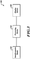
- FIGURE 3 illustrates a system 100 according to an embodiment of the invention.
- the system 100 includes an Interferometric radar device 102, a processing device 104, such as a computer, microprocessor or other appropriate computational device, and an optional display device 108, such as a synthetic vision system.
- the Interferometric radar device 102 transmits multiple simultaneous and/or sequential sensory (detection) signals.
- the display device 108 displays a representation of the terrain or other environment surveyed by the Interferometric radar device 102.
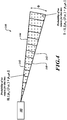
- FIGURE 4 consider a measurement made by the Interferometric radar device 102 of a spatial region 140 that can be modeled by an evidence grid. Center points 142 of cells of the evidence grid representing subregions of the region 140 are shown superimposed on the region 140. Additionally, the region 140 is illustrated as being divided into multiple bins 146, each of which includes one or more such cells and is a respective distance from the Interferometric radar device 102. The region 140 has some angular width ⁇ ( i.e., may be conical in configuration), within which a beam transmitted by the Interferometric radar device 102 will, with some probability, reflect off of a volume in space represented in the evidence grid by an occupied cell.
- ⁇ i.e., may be conical in configuration
- p 11 is the probability that a volume in space represented by an occupied cell reflects the beam, and can, but need not, make the assumption that this probability is independent both of the distance from the Interferometric radar device 102 (up to the maximum range of the Interferometric radar device), and of the angle from the central axis of the Interferometric radar device (up to the angular width of the beam).
- the radar measurement is actually a measurement not just at the distance r , but also returns information about bins 148 that are at a distance less than r from the Interferometric radar device 102.
- the probability that a theoretical radar measurement of an evidence grid is the same as a measurement of the actual sensed environment can be calculated as follows. The probability that a single cell makes a reflection is considered.
- the probability that there is no return is simply the probability that each of the cells in that range bin do not reflect the beam, which may be expressed as the product of the individual probabilities, ⁇ i p ⁇ i .
- the probability that there is a reflection given the state of the evidence grid is obtained by calculating the probability that there was no detection and subtracting from 1, or 1 - ⁇ i p ⁇ i . This simply states that in order to detect a reflection, at least one of the cells must have reflected the beam.
- the goal is to find the occupancies ⁇ i which maximize ⁇ . In so doing, the occupancies that are most likely to match the measurements of the actual sensed environment are found.
- the product in Eq. (9) is rearranged so that it is more transparent.
- the product k is over the radar beams for which the i th cell is in the beam but from which there is no return in the corresponding range bin
- the product over k ' is over the radar beams for which the i th cell is in the range bin for which there was a detection.
- This expression splits the dependence on ⁇ i into two parts. The first part is a measure of how often the cell is not seen by a radar beam. The second part is a measure of how well the current evidence grid supports the actual measured detections.
- Eq. (10) A few observations about the result in Eq. (10) follow. First, if a cell never appears in a detected range bin, then the second product in Eq. (10) (over k') is empty and the occupancy of the cell can be set to zero. In other words, if the cell is never in a detection range bin of any radar beam, then its occupancy can be set to zero. Second, if the first product in Eq. (10) is empty, then the cell has never been not seen by a radar beam. In this case, ⁇ i can be set to 1.
- FIGURE 5 illustrates a process 200 according to an embodiment of the invention.
- the process 200 is illustrated as a set of operations shown as discrete blocks.
- the process 200 may be implemented in any suitable hardware, software, firmware, or combination thereof.
- the process 200 may be implemented in computer-executable instructions that can be stored on a computer-readable medium and/or transferred from one computer, such as a server, to a second computer or other electronic device via a communications medium.
- the order in which the operations are described is not to be necessarily construed as a limitation.
- a first data set is received corresponding to a first detection signal transmitted over a first spatial region.
- the processing device 104 may receive data corresponding to a first measurement made of a first geographic area of interest by the Interferometric radar device 102.
- a second data set is received corresponding to a second detection signal transmitted over a second spatial region.
- the second region may have a first sub-region in common with the first region.
- the processing device 104 may receive data corresponding to a second measurement made of a second geographic area of interest by the Interferometric radar device 102.
- the second geographic area may be the same as or partially overlap the first geographic area.
- a first occupancy value is assigned to a first cell in an evidence grid.
- the first cell may represent the first sub-region.
- the first occupancy value characterizes whether an object has been detected by the first detection signal as being present in the first sub-region.
- the processing device 104 may generate an evidence grid corresponding to the first geographic area and assign occupancy values (i.e., occupied/unoccupied) to one or more of the cells in the grid based on the presence or absence of reflecting objects detected in the first geographic area.
- the processing device 104 may perform the optimum cell occupancy calculations described above herein.
- a representation of the first sub-region is displayed based on the probability calculation. For example, after performing the optimum cell occupancy calculations, the processing device 104 may generate a displayable model of the surveyed geographical regions to the display device 108.
- the evidence grid eliminates the ghost targets produced by the Interferometric radar device 102.
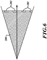
- regions 282 correspond to the target and ghosts, and the region 280 corresponds to no radar return at all. From this single return it is determined which of the regions 282 contains the target. All that is known is that there is at least one radar reflector in the combination of all the regions 282. But this is all that is ever known about the volumes from which there are a positive detection, e.g., the regions 282 in FIGURE 6 .
- the use of interferometry results in a disjoint but significantly smaller volume associated with a positive detection as compared to non-Interferometric radar signal. And so the evidence grid techniques enable one to combine different radar measurements to narrow down the location of targets.
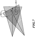
- FIGURE 7 shows an example of how combining two Interferometric radar measurements can easily eliminate ghost detections and determine where the target is.
- the ghost 282-1 are determined because they don't occupy the same location in space across the multiple radar scans. However, the target 282-2 does.
- an aircraft is traveling at 100 km/hr, 50 m above a flat plane with a cable initially located 1500 m in front of it.
- the radar takes a frame of data each 0.1 second.
- Each frame of data consists of a sweep in azimuth from -15° to +15° in 370 steps at a fixed elevation. The elevation is stepped from -3° to +3° in 1° steps.
- Radar data from this flight is fed into an evidence grid, with a cell size of 4 ⁇ 4m (horizontal) and 2 m (vertical).
- the vertical cell size of 2 m limits the vertical resolution to 2 m.
- the elevation of the radar is fixed, as might be the case for an approach to a runway.
- the range of stepping of elevation might not be large enough to ensure that the target is not in the beam at some elevation. In these cases, the elimination of the ghosts cannot be done through elevation stepping, as above, but rather through the forward motion of the aircraft.
- z t n z 0 + z t ⁇ z 0 cos n ⁇ ⁇ 2 ⁇ N 1 + N 2
- the y-component is, to first order, independent of the phase measurement and will be henceforth ignored.
- the only permissible values of n are those that lie within the original beamwidth of the radar, and if it is assumed that the vertical beamwidth of the radar is less than 6 degrees, then the permissible values of n are such that n N 1 + N 2 ⁇ ⁇ 1.
- x t (n) and z t ( n ) are the components of the position of the n th order ghost.
- the zeroth order ghost is the target.
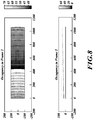
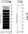
- FIGURE 10 The results of a simulation with a constant elevation are shown in FIGURE 10 .
- the ghosts are eliminated only by the forward motion of the aircraft. Since the vertical dimension of the evidence grid cell is 2 m, and since the distance from the initial position of the aircraft to the cable is 1500 m, from Eq. (15) it is estimated that the ghosts arising from the cable will disappear after the aircraft moves 122 m towards the cable, after 4.4 seconds and 44 frames of data.
- FIGURE 10 shows the last remnants of the ghosts of the cable after 4.2 seconds, just before they disappear, and after 44 frames of data have been taken, the cable ghosts have disappeared completely. ghosts associated with the ground plane are also disappearing in a similar manner at a similar rate.
Description
- The ability of a radar to precisely locate a target is limited by the beamwidth of the radar, since a radar return can come from anywhere in the cone formed by the beam. By making the beam as narrow as possible, the target can be located more precisely. However, physics dictates that in order to make the beam narrower, the physical size of the antenna must correspondingly increase. Thus, to precisely locate a target with a radar requires a large antenna.
- One way to escape from this physics-induced tradeoff is to use Interferometric methods, in which two or more radar receivers are used instead of the normal one. These receivers are placed a distance apart, and by comparing the differences in phase between the received signals, it is possible to obtain a much more accurate location of a target than with a single receiver. If there are enough receivers, it may be possible to localize the target without ambiguity. However, if we use only two receivers, or in certain geometries with more than two receivers, physics again limits the applicability of this approach. Because the phase can be measured only modulo 2π, the location of the target cannot be determined uniquely because of phase ambiguity. As a result, the target can be in any of a small number of discrete locations, each contained within the radar beam, and each located more precisely than is possible without the interferometry. The tradeoff with the Interferometric approach is between the precision with which we can locate the target, the number of receivers (and antennas required), and the introduction of a number of "ghost" targets. From a single radar return and using two receivers, there is no way to differentiate the true target from the ghost targets that arise from the phase ambiguities. In order to differentiate between the true target and the ghost targets, multiple radar returns must be utilized.
- The use of two or more receivers does have an additional drawback, in that the antenna design becomes more complicated. At worst, two or more separate antennas will be required; at best, one single antenna may be shared by the two or more receivers. However, with interferometry it is possible to achieve performance with two antennas (and two receivers) that is much superior to that achieved with a single receiver and a single antenna of twice the size.
- As shown in
FIGURE 1 the basic geometry of an Interferometric radar with tworeceivers receivers receivers receiver 10 is given, to first order in λN1/R by:
receivers 
receivers 
- Let Δθ and ΔΦ be the difference in elevation and azimuth, respectively, between the target position and the direction of the radar beam. Then the phase difference is

- Suppose now a measurement has been made, resulting in a measured phase difference of Φm ± δΦ. The measured phase difference is ambiguous. A measurement of Φm means only that the true phase difference is Φm + 2nπ, where n is any integer. Hence, solving Eq. (4) for Δθ, the following is determined:

- The possible values for n are limited only by the requirement that |Δθ| be less than the radar beamwidth. Only one of the possible values of n represents the target; the other values are ghost targets.
- Noteworthy is the dependence of the calculation of Δθ on δΦ, as this determines how accurately one can localize the target. Increasing the separation between the two
receivers receivers antenna 20 times larger. -
EP 2 103 957 - The present invention in its various aspects is as set out in the appended claims. In an embodiment of the invention, a system includes an Interferometric radar that transmits a first detection signal over a first spatial region and a second detection signal over a second spatial region. The second region has a first sub-region in common with the first region. The system further includes a processing device that assigns a first occupancy value to a first cell in an evidence grid. The first cell represents the first sub-region, and the first occupancy value characterizes whether an object has been detected by the first detection signal as being present in the first sub-region. The processing device calculates, based on the first and second detection signals, the probability that the first occupancy value accurately characterizes the presence of the object in the first sub-region, and generates a data representation of the first sub-region based on the probability calculation.
- The combination of the evidence grid with the Interferometric radar provides a powerful tool with many applications. The evidence grid provides a means to eliminate the ambiguities (i.e., ghosts) associated with the use of interferometry using only two receivers, while the capabilities of the Interferometric radar provides sensor data to the evidence grid that is far superior to that from a non-Interferometric radar.
- Preferred and alternative embodiments of the present invention are described in detail below with reference to the following drawings.
-
FIGURE 1 illustrates a geometric relationship of signals produced/received by an Interferometric radar; -
FIGURE 2 illustrates two different radar measurements; -
FIGURE 3 illustrates a system formed in accordance with to an embodiment of the invention; -
FIGURE 4 a spatial region that can be modeled by an evidence grid according to an embodiment of the invention; -
FIGURE 5 illustrates a process according to an embodiment of the invention; -
FIGURE 6 shows target results of a single Interferometric radar signal; -
FIGURE 7 shows a combined result of Interferometric radar signals using the present invention; and -
FIGURES 8-10 show output of an Interferometric radar after different numbers of frames of data. - An evidence grid at its most basic is a collection of points and a measure of occupancy at each of these points. Typically, the collection of points forms a uniform grid in three-dimensions, but the uniformity is not required. The measure of occupancy of a cell in the three-dimensional grid can be interpreted as the probability that the cell is occupied. A question addressed herein is how to arrange the occupancies of the cells in the evidence grid so as to match as well as possible the measurements corresponding to the sensed environment.
- An approach includes asking the related question: given a proposed evidence grid, with probabilities of occupancy assumed for each cell, what is the probability that (modeled) measurements of the cells in this evidence grid will match (actual) measurements of the real world? If we can make that calculation as a function of the occupancies of the cells, then we can turn the problem of how to fill out the occupancies of the cells in the evidence grid into a related optimization problem, to find the occupancies of the cells that maximize the probability that those (modeled) measurements of the evidence grid match the (actual) measurements of the real world.
- The evidence grid is a method of accumulating knowledge about a volume to determine what parts of the area are occupied by obstacles. The volume is divided up into cells, and the results of the measurements are used to determine whether the cells are occupied or not. An important part of this determination is the use of negative inferencing, so that the lack of a return from a radar measurement can be used as evidence that some part of the volume is unoccupied. As shown in
FIGURE 2 ,areas 40 show the volumes in space corresponding to radar bins in which there were positive radar returns. At least some portion of these volumes must be occupied in order to have a positive return.Areas 42 correspond to those radar bins in which there was no radar return above a threshold; hence, those areas are unoccupied. Considering thearea 40 which overlaps thearea 42, the only part of thearea 40 which can be occupied is the part of thearea 40 which does not intersect thearea 42. By doing this, one can narrow down which parts of the volume are occupied, and so increase the resolution of the measurements beyond what would be possible with a single radar measurement. -
FIGURE 3 illustrates asystem 100 according to an embodiment of the invention. Thesystem 100 includes anInterferometric radar device 102, aprocessing device 104, such as a computer, microprocessor or other appropriate computational device, and anoptional display device 108, such as a synthetic vision system. TheInterferometric radar device 102 transmits multiple simultaneous and/or sequential sensory (detection) signals. Thedisplay device 108 displays a representation of the terrain or other environment surveyed by theInterferometric radar device 102. - Referring now to
FIGURE 4 , consider a measurement made by theInterferometric radar device 102 of aspatial region 140 that can be modeled by an evidence grid. Center points 142 of cells of the evidence grid representing subregions of theregion 140 are shown superimposed on theregion 140. Additionally, theregion 140 is illustrated as being divided intomultiple bins 146, each of which includes one or more such cells and is a respective distance from theInterferometric radar device 102. Theregion 140 has some angular width Φ (i.e., may be conical in configuration), within which a beam transmitted by theInterferometric radar device 102 will, with some probability, reflect off of a volume in space represented in the evidence grid by an occupied cell. For simplicity, p11 is the probability that a volume in space represented by an occupied cell reflects the beam, and can, but need not, make the assumption that this probability is independent both of the distance from the Interferometric radar device 102 (up to the maximum range of the Interferometric radar device), and of the angle from the central axis of the Interferometric radar device (up to the angular width of the beam). - Similarly, p00 is the probability that a volume in space represented by an unoccupied cell does not reflect the beam. From these, we can easily obtain the probability that a volume in space represented by an unoccupied cell reflects the beam (a false positive response from the Interferometric radar device) as p10 = 1 - poo, and also the probability that a volume in space represented by an occupied cell does not reflect the beam (a false negative response) as p01 = 1 - p11.
- Now suppose one of the actual radar measurements results in a first detection at some
bin 146 at a distance r from theInterferometric radar device 102. The radar measurement is actually a measurement not just at the distance r, but also returns information aboutbins 148 that are at a distance less than r from theInterferometric radar device 102. Hence, the probability that a theoretical radar measurement of an evidence grid is the same as a measurement of the actual sensed environment can be calculated as follows. The probability that a single cell makes a reflection is considered. Letting ρi be the probability that the ith cell in the evidence grid is occupied, then the probability that the ith cell produces a reflection is:

- For each range bin up to but not including the range bin within which an object is detected, the probability that there is no return is simply the probability that each of the cells in that range bin do not reflect the beam, which may be expressed as the product of the individual probabilities, Π ip̃i . For the
range bin 146 in which there was an object detection, the probability that there is a reflection given the state of the evidence grid is obtained by calculating the probability that there was no detection and subtracting from 1, or 1 - Π ip̃i . This simply states that in order to detect a reflection, at least one of the cells must have reflected the beam. The net result for the probability that a theoretical radar measurement of the evidence grid matches the actual radar measurement of the sensed environment is thus
Interferometric radar device 102 than the range bin in which there was an object detection, and the subscript jk runs in the kth radar beam over all of the cells lying in the range bin in which there was an object detection. Then, theprocessing device 104 can calculate the probability that all of the theoretical radar measurements made on the evidence grid matches the actual measurements made by multiple beams transmitted by theInterferometric radar device 102 as
- The goal is to find the occupancies ρi which maximize β. In so doing, the occupancies that are most likely to match the measurements of the actual sensed environment are found.
- The product in Eq. (9) is rearranged so that it is more transparent. In particular, the dependence of β on the occupancy of a single cell is as follows:

- A few observations about the result in Eq. (10) follow. First, if a cell never appears in a detected range bin, then the second product in Eq. (10) (over k') is empty and the occupancy of the cell can be set to zero. In other words, if the cell is never in a detection range bin of any radar beam, then its occupancy can be set to zero. Second, if the first product in Eq. (10) is empty, then the cell has never been not seen by a radar beam. In this case, ρi can be set to 1.
- To solve for the optimum occupancies for those cells which cannot be trivially set to 0 or 1, one may examine more closely the quantity inside the braces in Eq. (10), P(ρi). An embodiment seeks the maximum of β with respect to the ρi, subject to the constraint that 0 ≤ ρi ≤ 1 (since ρi is a probability of occupancy).
- The maximum of β is attained when one of the following conditions is met for each cell (note that this optimization is a constrained optimization, since 0 ≤ ρi≤1):

- Solving these equations for the optimum point may be done in a conventional manner, such as using, for example, a steepest-descent method. Each of the calculations discussed above herein may be performed completely or partially by the
processing device 104. -
FIGURE 5 illustrates aprocess 200 according to an embodiment of the invention. Theprocess 200 is illustrated as a set of operations shown as discrete blocks. Theprocess 200 may be implemented in any suitable hardware, software, firmware, or combination thereof. As such theprocess 200 may be implemented in computer-executable instructions that can be stored on a computer-readable medium and/or transferred from one computer, such as a server, to a second computer or other electronic device via a communications medium. The order in which the operations are described is not to be necessarily construed as a limitation. - At a
block 210, a first data set is received corresponding to a first detection signal transmitted over a first spatial region. For example, theprocessing device 104 may receive data corresponding to a first measurement made of a first geographic area of interest by theInterferometric radar device 102. - At a
block 220, a second data set is received corresponding to a second detection signal transmitted over a second spatial region. The second region may have a first sub-region in common with the first region. For example, theprocessing device 104 may receive data corresponding to a second measurement made of a second geographic area of interest by theInterferometric radar device 102. The second geographic area may be the same as or partially overlap the first geographic area. - At a
block 230, based on the first data set, a first occupancy value is assigned to a first cell in an evidence grid. The first cell may represent the first sub-region. The first occupancy value characterizes whether an object has been detected by the first detection signal as being present in the first sub-region. For example, theprocessing device 104 may generate an evidence grid corresponding to the first geographic area and assign occupancy values (i.e., occupied/unoccupied) to one or more of the cells in the grid based on the presence or absence of reflecting objects detected in the first geographic area. - At a
block 240, based on the first and second data sets, the probability that the first occupancy value accurately characterizes the presence of the object in the first sub-region is calculated. For example, theprocessing device 104 may perform the optimum cell occupancy calculations described above herein. - At a
block 250, a representation of the first sub-region is displayed based on the probability calculation. For example, after performing the optimum cell occupancy calculations, theprocessing device 104 may generate a displayable model of the surveyed geographical regions to thedisplay device 108. - The evidence grid eliminates the ghost targets produced by the
Interferometric radar device 102. Consider a single radar return with Interferometric ghosts, as depicted inFIGURE 6 , whereregions 282 correspond to the target and ghosts, and theregion 280 corresponds to no radar return at all. From this single return it is determined which of theregions 282 contains the target. All that is known is that there is at least one radar reflector in the combination of all theregions 282. But this is all that is ever known about the volumes from which there are a positive detection, e.g., theregions 282 inFIGURE 6 . The use of interferometry results in a disjoint but significantly smaller volume associated with a positive detection as compared to non-Interferometric radar signal. And so the evidence grid techniques enable one to combine different radar measurements to narrow down the location of targets. -
FIGURE 7 shows an example of how combining two Interferometric radar measurements can easily eliminate ghost detections and determine where the target is. The ghost 282-1 are determined because they don't occupy the same location in space across the multiple radar scans. However, the target 282-2 does. - From Eqs. (1-4) it is clear that rotating the radar in either elevation or in azimuth, without changing the position of the radar, will not provide any change in the location of the ghosts, at least to first order in the angles between the target location and the nominal beam direction, assuming that the beamwidth of the radar is small enough in both directions that first order is a good approximation. However,
this is true only as long as the target remains within the beam. If one were to change the elevation of the radar just enough that the target is no longer in the beam, any of the ghost locations that lie within the new beam will be quickly identified as ghosts. - In one example, an aircraft is traveling at 100 km/hr, 50 m above a flat plane with a cable initially located 1500 m in front of it. The radar, with a range limitation of 2048 m and a bin size of 1 m, takes a frame of data each 0.1 second. Each frame of data consists of a sweep in azimuth from -15° to +15° in 370 steps at a fixed elevation. The elevation is stepped from -3° to +3° in 1° steps. Radar data from this flight is fed into an evidence grid, with a cell size of 4 × 4m (horizontal) and 2 m (vertical). The vertical cell size of 2 m limits the vertical resolution to 2 m.
-
FIGURE 8 shows an example output of the evidence grid for theInterferometric radar 102 after the first 3 frames of data have been analyzed. Since the elevations for these 3 frames are -3°, -2°, and -1°, the targets are within the beam for all three frames. (The ground is one target, a flat plane at an elevation of 0; the cable is the second target, at x = 500 inFIGURE 8 .) Consequently, the ghosts cannot be eliminated and show up clearly. As the elevation is stepped to higher values, the ghosts are eliminated. By the time that the seventh frame of data has been processed by the evidence grid, all ghosts have been eliminated, as shown inFIGURE 9 , with only the flat ground plane and the cable remaining. The increased resolution in the vertical axis available with the Interferometric radar leads to a dramatic improvement in the ability of the evidence grid to model the scene. - In one embodiment, the elevation of the radar is fixed, as might be the case for an approach to a runway. Or the range of stepping of elevation might not be large enough to ensure that the target is not in the beam at some elevation. In these cases, the elimination of the ghosts cannot be done through elevation stepping, as above, but rather through the forward motion of the aircraft.
- From Eq. (4), the locations of the target and ghosts, as obtained by the Interferometric radar are as follows:


- In these equations, n = 0 represents the true target; the ghosts occur for non-zero n. The y-component is, to first order, independent of the phase measurement and will be henceforth ignored. The only permissible values of n are those that lie within the original beamwidth of the radar, and if it is assumed that the vertical beamwidth of the radar is less than 6 degrees, then the permissible values of n are such that


- The results of a simulation with a constant elevation are shown in
FIGURE 10 . In this case, the ghosts are eliminated only by the forward motion of the aircraft. Since the vertical dimension of the evidence grid cell is 2 m, and since the distance from the initial position of the aircraft to the cable is 1500 m, from Eq. (15) it is estimated that the ghosts arising from the cable will disappear after the aircraft moves 122 m towards the cable, after 4.4 seconds and 44 frames of data.FIGURE 10 shows the last remnants of the ghosts of the cable after 4.2 seconds, just before they disappear, and after 44 frames of data have been taken, the cable ghosts have disappeared completely. Ghosts associated with the ground plane are also disappearing in a similar manner at a similar rate.
Claims (9)
- A method for a system comprising an interferometric radar (102), a processing device (104) and a display device (108), the method comprising:a) receiving (210) at the processing device a first data set corresponding to a first detection signal transmitted over a first spatial region;b) receiving (220) at the processing device a second data set corresponding to a second detection signal transmitted over a second spatial region, the second region having a first sub-region in common with the first region, wherein the first and second data set are radar reflections produced by an Interferometric radar;c) based on the first data set, assigning (230) by the processing device a first occupancy value to a first cell in an evidence grid, the first cell representing the first sub-region, the first occupancy value characterizing whether an object has been detected by the first detection signal as being present in the first sub-region;d) calculating (240) by the processing device, based on the first and second data sets, the probability that the first occupancy value accurately characterizes the presence of the object in the first sub-region;e) displaying (250) by the display device a representation of the first sub-region based on the probability calculation; and
repeating a)-d), wherein calculating comprises eliminating ghost radar returns after a plurality of repetitions of a)-d). - The method of Claim 1, wherein the evidence grid comprises a three-dimensional grid.
- The method of Claim 1, wherein calculating the probability comprises calculating the probability that the first sub-region represented by the first cell reflects at least one of the plurality of detection signals, wherein calculating the probability further comprises calculating the probability that the first sub-region represented by the first cell does not reflect at least one of the plurality of detection signals, wherein each of the first and second spatial regions comprises a respective plurality of volumetric bins, each said bin comprising at least one sub-region, the first sub-region being located in at least one of the bins, each sub-region being represented by a corresponding cell in the evidence grid and calculating the probability further comprises calculating a first probability that each sub-region within a first bin of the first spatial region does not reflect at least one of the plurality of detection signals and a second probability that each sub-region within a first bin of the second spatial region does not reflect at least one of the plurality of detection signals.
- The method of Claim 3, wherein calculating the probability further comprises calculating a third probability that each sub-region within a second bin of the first spatial region reflects at least one of the plurality of detection signals and a fourth probability that each sub-region within a second bin of the second spatial region does not reflect at least one of the plurality of detection signals.
- The method of Claim 4, wherein calculating the probability further comprises:calculating a first product of the first probability corresponding to at least one bin of the first spatial region and the third probability corresponding to at least one bin of the first spatial region; andcalculating a second product of the second probability corresponding to at least one bin of the second spatial region and the fourth probability corresponding to at least one bin of the second spatial region,wherein calculating the probability further comprises calculating a third product of the first and second products or calculating the maximum of the third product.
- A system (100) comprising:an Interferometric radar (102) configured to transmit a first detection signal over a first spatial region, receive any radar reflections associated with the first detection signal, transmit a second detection signal over a second spatial region and receive any radar reflections associated with the second detection signal, the second region having a first sub-region in common with the first region;a processing device (104) configured to receive from the interferometric radar the reflections associated with the first detection signal and the reflections associated with the second detection signal, the processing device further configured to:a) assign, based on the reflections associated with the first detection signal, a first occupancy value to a first cell in an evidence grid, the first cell representing the first sub-region, the first occupancy value characterizing whether an object has been detected by the first detection signal as being present in the first sub-region,b) calculate, based on the reflections associated with the first and second detection signals, the probability that the first occupancy value accurately characterizes the presence of the object in the first sub-region, andc) generate a data representation of the first sub-region based on the probability calculation; and a display device (108) configured to produce an output based on the generated data representation,wherein the processing device is further configured to eliminate ghost radar returns after the Interferometric radar sends more detection signals and receives associated reflections and the processing device repeats a)-c) based on the additional reflections received.
- The system of Claim 6, wherein the processing device is further configured to calculate the probability that the first sub-region represented by the first cell reflects at least one of the plurality of detection signals or calculate the probability that the first sub-region represented by the first cell does not reflect at least one of the plurality of detection signals.
- The system of Claim 7, wherein:each of the first and second spatial regions comprises a respective plurality of volumetric bins, each said bin comprising at least one sub-region, the first sub-region being located in at least one of the bins, each sub-region being represented by a corresponding cell in the evidence grid; andthe processing device is further configured to calculate a first probability that each sub-region within a first bin of the first spatial region does not reflect at least one of the plurality of detection signals and a second probability that each sub-region within a first bin of the second spatial region does not reflect at least one of the plurality of detection signals.
- The system of Claim 8, wherein the processing device is further configured to calculate a third probability that each sub-region within a second bin of the first spatial region reflects at least one of the plurality of detection signals and a fourth probability that each sub-region within a second bin of the second spatial region does not reflect at least one of the plurality of detection signals, wherein the processing device is further configured to:calculate a first product of the first probability corresponding to at least one bin of the first spatial region and the third probability corresponding to at least one bin of the first spatial region; andcalculate a second product of the second probability corresponding to at least one bin of the second spatial region and the fourth probability corresponding to at least one bin of the second spatial region,wherein the processing device is further configured to calculate a third product of the first and second products or calculate the maximum of the third product.
Applications Claiming Priority (1)
| Application Number | Priority Date | Filing Date | Title |
|---|---|---|---|
| US12/817,918 US8391553B2 (en) | 2008-03-19 | 2010-06-17 | Systems and methods for using an evidence grid to eliminate ambiguities in an interferometric radar |
Publications (2)
| Publication Number | Publication Date |
|---|---|
| EP2397866A1 EP2397866A1 (en) | 2011-12-21 |
| EP2397866B1 true EP2397866B1 (en) | 2017-09-13 |
Family
ID=44118312
Family Applications (1)
| Application Number | Title | Priority Date | Filing Date |
|---|---|---|---|
| EP11168969.1A Active EP2397866B1 (en) | 2010-06-17 | 2011-06-07 | Systems and methods for using an evidence grid to eliminate ambiguities in an interferometric radar |
Country Status (4)
| Country | Link |
|---|---|
| US (1) | US8391553B2 (en) |
| EP (1) | EP2397866B1 (en) |
| JP (1) | JP5977486B2 (en) |
| CN (1) | CN102338868A (en) |
Families Citing this family (7)
| Publication number | Priority date | Publication date | Assignee | Title |
|---|---|---|---|---|
| US20150192668A1 (en) * | 2014-01-06 | 2015-07-09 | Honeywell International Inc. | Mathematically combining remote sensing data with different resolution to create 3d maps |
| EP3182155A1 (en) * | 2015-12-17 | 2017-06-21 | Autoliv Development AB | A vehicle radar system arranged for determining an unoccupied domain |
| IT201600094991A1 (en) * | 2016-09-21 | 2018-03-21 | Ids Georadar S R L | MULTI-BISTATIC GROUND INTERFEROMETRIC RADAR SYSTEM FOR THE MEASUREMENT OF 2D and 3D DEFORMATIONS |
| US10338216B2 (en) * | 2016-11-04 | 2019-07-02 | GM Global Technology Operations LLC | Object detection in multiple radars |
| US10473775B2 (en) | 2017-03-20 | 2019-11-12 | David Slemp | Frequency modulated continuous wave antenna system |
| CN110687512A (en) * | 2019-07-02 | 2020-01-14 | 中国航空工业集团公司雷华电子技术研究所 | Multi-machine heterogeneous radar cooperative TBD processing method based on probability matrix |
| US11175370B1 (en) * | 2020-05-27 | 2021-11-16 | Bae Systems Information And Electronic Systems Integration Inc. | Multiple long baseline interferometry geolocation |
Family Cites Families (18)
| Publication number | Priority date | Publication date | Assignee | Title |
|---|---|---|---|---|
| US4975704A (en) * | 1990-01-26 | 1990-12-04 | The United States Of America As Represented By The Administrator Of The National Aeronautics And Space Administration | Method for detecting surface motions and mapping small terrestrial or planetary surface deformations with synthetic aperture radar |
| JP3147541B2 (en) * | 1992-11-06 | 2001-03-19 | 株式会社豊田中央研究所 | Obstacle recognition device for vehicles |
| FR2709834B1 (en) | 1993-09-10 | 1995-11-10 | Framatome Sa | Method and device for detecting and locating obstacles in the environment of a vehicle. |
| JP3301292B2 (en) * | 1995-12-12 | 2002-07-15 | 三菱電機株式会社 | Interferometric high-resolution radar device and terrain height measuring method using high-resolution radar device |
| JP2000292538A (en) * | 1999-04-07 | 2000-10-20 | Mitsubishi Electric Corp | Obstacle detector for vehicle |
| JP2005003579A (en) * | 2003-06-13 | 2005-01-06 | Mitsubishi Electric Corp | Angle measurement system and positioning system |
| JP2005140639A (en) * | 2003-11-06 | 2005-06-02 | Mitsubishi Electric Corp | Distributed aperture radar system |
| JP2005308428A (en) * | 2004-04-19 | 2005-11-04 | Mitsubishi Electric Corp | Position estimation system |
| US7142150B2 (en) * | 2004-12-15 | 2006-11-28 | Deere & Company | Method and system for detecting an object using a composite evidence grid |
| FR2890774B1 (en) | 2005-09-09 | 2007-11-16 | Inst Nat Rech Inf Automat | VEHICLE DRIVING ASSISANCE METHOD AND IMPROVED ASSOCIATED DEVICE |
| US7783612B2 (en) * | 2005-09-21 | 2010-08-24 | The Boeing Company | Creation of optimized terrain databases |
| US7417586B2 (en) * | 2006-02-07 | 2008-08-26 | Honeywell International Inc. | Methods and systems for interferometric cross track phase calibration |
| US7372393B2 (en) * | 2006-07-07 | 2008-05-13 | Mitsubishi Electric Research Laboratories, Inc. | Method and system for determining unwrapped phases from noisy two-dimensional wrapped-phase images |
| DE102006047131A1 (en) * | 2006-10-05 | 2008-04-10 | Robert Bosch Gmbh | Method for automatically controlling a vehicle |
| JP4855304B2 (en) * | 2007-03-06 | 2012-01-18 | 三菱電機株式会社 | Image radar signal processor |
| US7609200B1 (en) * | 2007-05-29 | 2009-10-27 | Rockwell Collins, Inc. | Radar derived perspective display system |
| US8311695B2 (en) * | 2008-03-19 | 2012-11-13 | Honeywell International Inc. | Construction of evidence grid from multiple sensor measurements |
| US8244455B2 (en) * | 2008-09-09 | 2012-08-14 | Honeywell International Inc. | Apparatus and method for determining the position of a vehicle with respect to a terrain |
-
2010
- 2010-06-17 US US12/817,918 patent/US8391553B2/en active Active
-
2011
- 2011-06-07 EP EP11168969.1A patent/EP2397866B1/en active Active
- 2011-06-09 JP JP2011129205A patent/JP5977486B2/en not_active Expired - Fee Related
- 2011-06-16 CN CN2011101624259A patent/CN102338868A/en active Pending
Non-Patent Citations (1)
| Title |
|---|
| None * |
Also Published As
| Publication number | Publication date |
|---|---|
| CN102338868A (en) | 2012-02-01 |
| JP5977486B2 (en) | 2016-08-24 |
| US8391553B2 (en) | 2013-03-05 |
| US20100271255A1 (en) | 2010-10-28 |
| EP2397866A1 (en) | 2011-12-21 |
| JP2012002809A (en) | 2012-01-05 |
Similar Documents
| Publication | Publication Date | Title |
|---|---|---|
| EP2397866B1 (en) | Systems and methods for using an evidence grid to eliminate ambiguities in an interferometric radar | |
| KR102252219B1 (en) | Adaptive scanning method and system using optical distance measurement system | |
| US9939522B2 (en) | Systems and methods for 4-dimensional radar tracking | |
| EP2103957B1 (en) | Construction of evidence grid from multiple sensor measurements | |
| Daun et al. | Tracking in multistatic passive radar systems using DAB/DVB-T illumination | |
| US6219594B1 (en) | Landing area obstacle detection radar system | |
| US10175348B2 (en) | Use of range-rate measurements in a fusion tracking system via projections | |
| KR100852103B1 (en) | Altitude estimation system and method | |
| US8981990B2 (en) | Three dimensional radar system | |
| US20020147544A1 (en) | High resolution autonomous precision positioning system | |
| CN110678772B (en) | Enhanced vertical object detection for vehicle radar systems | |
| EP2573582B1 (en) | Systems and methods for combining a priori data with sensor data | |
| AU2017232034B2 (en) | Ground-based, multi-bistatic interferometric radar system for measuring 2d and 3d deformations | |
| Magnard et al. | Analysis of a maximum likelihood phase estimation method for airborne multibaseline SAR interferometry | |
| US9933519B2 (en) | Three dimensional radar system | |
| RU2569843C1 (en) | Method of forming three-dimensional image of earth's surface in on-board doppler radar station with linear antenna array | |
| Johnsen et al. | Bi-and multistatic radar | |
| Michelini et al. | Deformation vector measurement by means of ground based interferometric radar system | |
| US20190339378A1 (en) | Acquiring information regarding a volume using wireless networks | |
| Cabalkova et al. | Comparison of target detections from active MSPSR system with outputs of MLAT system | |
| Soysal et al. | Information analysis in passive radar networks for target tracking | |
| Koch | Advanced Target Tracking for Applications in Multistatic Systems | |
| del Corte Valiente et al. | Localization Techniques Based on Ray-Tracing for Transportation Systems: The Case of Adolfo Suarez Madrid-Barajas Airport | |
| Kabakchiev et al. | Height Target Estimation in a Three Positioned Radar System |
Legal Events
| Date | Code | Title | Description |
|---|---|---|---|
| 17P | Request for examination filed |
Effective date: 20110607 |
|
| AK | Designated contracting states |
Kind code of ref document: A1 Designated state(s): AL AT BE BG CH CY CZ DE DK EE ES FI FR GB GR HR HU IE IS IT LI LT LU LV MC MK MT NL NO PL PT RO RS SE SI SK SM TR |
|
| AX | Request for extension of the european patent |
Extension state: BA ME |
|
| PUAI | Public reference made under article 153(3) epc to a published international application that has entered the european phase |
Free format text: ORIGINAL CODE: 0009012 |
|
| RAP1 | Party data changed (applicant data changed or rights of an application transferred) |
Owner name: HONEYWELL INTERNATIONAL INC. |
|
| GRAP | Despatch of communication of intention to grant a patent |
Free format text: ORIGINAL CODE: EPIDOSNIGR1 |
|
| INTG | Intention to grant announced |
Effective date: 20170419 |
|
| GRAS | Grant fee paid |
Free format text: ORIGINAL CODE: EPIDOSNIGR3 |
|
| GRAA | (expected) grant |
Free format text: ORIGINAL CODE: 0009210 |
|
| AK | Designated contracting states |
Kind code of ref document: B1 Designated state(s): AL AT BE BG CH CY CZ DE DK EE ES FI FR GB GR HR HU IE IS IT LI LT LU LV MC MK MT NL NO PL PT RO RS SE SI SK SM TR |
|
| REG | Reference to a national code |
Ref country code: GB Ref legal event code: FG4D |
|
| REG | Reference to a national code |
Ref country code: CH Ref legal event code: EP |
|
| REG | Reference to a national code |
Ref country code: IE Ref legal event code: FG4D |
|
| REG | Reference to a national code |
Ref country code: AT Ref legal event code: REF Ref document number: 928698 Country of ref document: AT Kind code of ref document: T Effective date: 20171015 |
|
| REG | Reference to a national code |
Ref country code: DE Ref legal event code: R096 Ref document number: 602011041504 Country of ref document: DE |
|
| REG | Reference to a national code |
Ref country code: NL Ref legal event code: MP Effective date: 20170913 |
|
| REG | Reference to a national code |
Ref country code: LT Ref legal event code: MG4D |
|
| PG25 | Lapsed in a contracting state [announced via postgrant information from national office to epo] |
Ref country code: NO Free format text: LAPSE BECAUSE OF FAILURE TO SUBMIT A TRANSLATION OF THE DESCRIPTION OR TO PAY THE FEE WITHIN THE PRESCRIBED TIME-LIMIT Effective date: 20171213 Ref country code: LT Free format text: LAPSE BECAUSE OF FAILURE TO SUBMIT A TRANSLATION OF THE DESCRIPTION OR TO PAY THE FEE WITHIN THE PRESCRIBED TIME-LIMIT Effective date: 20170913 Ref country code: SE Free format text: LAPSE BECAUSE OF FAILURE TO SUBMIT A TRANSLATION OF THE DESCRIPTION OR TO PAY THE FEE WITHIN THE PRESCRIBED TIME-LIMIT Effective date: 20170913 Ref country code: FI Free format text: LAPSE BECAUSE OF FAILURE TO SUBMIT A TRANSLATION OF THE DESCRIPTION OR TO PAY THE FEE WITHIN THE PRESCRIBED TIME-LIMIT Effective date: 20170913 Ref country code: HR Free format text: LAPSE BECAUSE OF FAILURE TO SUBMIT A TRANSLATION OF THE DESCRIPTION OR TO PAY THE FEE WITHIN THE PRESCRIBED TIME-LIMIT Effective date: 20170913 |
|
| REG | Reference to a national code |
Ref country code: AT Ref legal event code: MK05 Ref document number: 928698 Country of ref document: AT Kind code of ref document: T Effective date: 20170913 |
|
| PG25 | Lapsed in a contracting state [announced via postgrant information from national office to epo] |
Ref country code: LV Free format text: LAPSE BECAUSE OF FAILURE TO SUBMIT A TRANSLATION OF THE DESCRIPTION OR TO PAY THE FEE WITHIN THE PRESCRIBED TIME-LIMIT Effective date: 20170913 Ref country code: BG Free format text: LAPSE BECAUSE OF FAILURE TO SUBMIT A TRANSLATION OF THE DESCRIPTION OR TO PAY THE FEE WITHIN THE PRESCRIBED TIME-LIMIT Effective date: 20171213 Ref country code: ES Free format text: LAPSE BECAUSE OF FAILURE TO SUBMIT A TRANSLATION OF THE DESCRIPTION OR TO PAY THE FEE WITHIN THE PRESCRIBED TIME-LIMIT Effective date: 20170913 Ref country code: RS Free format text: LAPSE BECAUSE OF FAILURE TO SUBMIT A TRANSLATION OF THE DESCRIPTION OR TO PAY THE FEE WITHIN THE PRESCRIBED TIME-LIMIT Effective date: 20170913 Ref country code: GR Free format text: LAPSE BECAUSE OF FAILURE TO SUBMIT A TRANSLATION OF THE DESCRIPTION OR TO PAY THE FEE WITHIN THE PRESCRIBED TIME-LIMIT Effective date: 20171214 |
|
| PG25 | Lapsed in a contracting state [announced via postgrant information from national office to epo] |
Ref country code: NL Free format text: LAPSE BECAUSE OF FAILURE TO SUBMIT A TRANSLATION OF THE DESCRIPTION OR TO PAY THE FEE WITHIN THE PRESCRIBED TIME-LIMIT Effective date: 20170913 |
|
| PG25 | Lapsed in a contracting state [announced via postgrant information from national office to epo] |
Ref country code: CZ Free format text: LAPSE BECAUSE OF FAILURE TO SUBMIT A TRANSLATION OF THE DESCRIPTION OR TO PAY THE FEE WITHIN THE PRESCRIBED TIME-LIMIT Effective date: 20170913 Ref country code: PL Free format text: LAPSE BECAUSE OF FAILURE TO SUBMIT A TRANSLATION OF THE DESCRIPTION OR TO PAY THE FEE WITHIN THE PRESCRIBED TIME-LIMIT Effective date: 20170913 Ref country code: RO Free format text: LAPSE BECAUSE OF FAILURE TO SUBMIT A TRANSLATION OF THE DESCRIPTION OR TO PAY THE FEE WITHIN THE PRESCRIBED TIME-LIMIT Effective date: 20170913 |
|
| PG25 | Lapsed in a contracting state [announced via postgrant information from national office to epo] |
Ref country code: SK Free format text: LAPSE BECAUSE OF FAILURE TO SUBMIT A TRANSLATION OF THE DESCRIPTION OR TO PAY THE FEE WITHIN THE PRESCRIBED TIME-LIMIT Effective date: 20170913 Ref country code: IT Free format text: LAPSE BECAUSE OF FAILURE TO SUBMIT A TRANSLATION OF THE DESCRIPTION OR TO PAY THE FEE WITHIN THE PRESCRIBED TIME-LIMIT Effective date: 20170913 Ref country code: AT Free format text: LAPSE BECAUSE OF FAILURE TO SUBMIT A TRANSLATION OF THE DESCRIPTION OR TO PAY THE FEE WITHIN THE PRESCRIBED TIME-LIMIT Effective date: 20170913 Ref country code: IS Free format text: LAPSE BECAUSE OF FAILURE TO SUBMIT A TRANSLATION OF THE DESCRIPTION OR TO PAY THE FEE WITHIN THE PRESCRIBED TIME-LIMIT Effective date: 20180113 Ref country code: EE Free format text: LAPSE BECAUSE OF FAILURE TO SUBMIT A TRANSLATION OF THE DESCRIPTION OR TO PAY THE FEE WITHIN THE PRESCRIBED TIME-LIMIT Effective date: 20170913 Ref country code: SM Free format text: LAPSE BECAUSE OF FAILURE TO SUBMIT A TRANSLATION OF THE DESCRIPTION OR TO PAY THE FEE WITHIN THE PRESCRIBED TIME-LIMIT Effective date: 20170913 |
|
| REG | Reference to a national code |
Ref country code: DE Ref legal event code: R097 Ref document number: 602011041504 Country of ref document: DE |
|
| REG | Reference to a national code |
Ref country code: FR Ref legal event code: PLFP Year of fee payment: 8 |
|
| PLBE | No opposition filed within time limit |
Free format text: ORIGINAL CODE: 0009261 |
|
| STAA | Information on the status of an ep patent application or granted ep patent |
Free format text: STATUS: NO OPPOSITION FILED WITHIN TIME LIMIT |
|
| PG25 | Lapsed in a contracting state [announced via postgrant information from national office to epo] |
Ref country code: DK Free format text: LAPSE BECAUSE OF FAILURE TO SUBMIT A TRANSLATION OF THE DESCRIPTION OR TO PAY THE FEE WITHIN THE PRESCRIBED TIME-LIMIT Effective date: 20170913 |
|
| 26N | No opposition filed |
Effective date: 20180614 |
|
| PG25 | Lapsed in a contracting state [announced via postgrant information from national office to epo] |
Ref country code: SI Free format text: LAPSE BECAUSE OF FAILURE TO SUBMIT A TRANSLATION OF THE DESCRIPTION OR TO PAY THE FEE WITHIN THE PRESCRIBED TIME-LIMIT Effective date: 20170913 |
|
| REG | Reference to a national code |
Ref country code: CH Ref legal event code: PL |
|
| REG | Reference to a national code |
Ref country code: BE Ref legal event code: MM Effective date: 20180630 |
|
| REG | Reference to a national code |
Ref country code: IE Ref legal event code: MM4A |
|
| PG25 | Lapsed in a contracting state [announced via postgrant information from national office to epo] |
Ref country code: MC Free format text: LAPSE BECAUSE OF FAILURE TO SUBMIT A TRANSLATION OF THE DESCRIPTION OR TO PAY THE FEE WITHIN THE PRESCRIBED TIME-LIMIT Effective date: 20170913 Ref country code: LU Free format text: LAPSE BECAUSE OF NON-PAYMENT OF DUE FEES Effective date: 20180607 |
|
| PG25 | Lapsed in a contracting state [announced via postgrant information from national office to epo] |
Ref country code: IE Free format text: LAPSE BECAUSE OF NON-PAYMENT OF DUE FEES Effective date: 20180607 Ref country code: LI Free format text: LAPSE BECAUSE OF NON-PAYMENT OF DUE FEES Effective date: 20180630 Ref country code: CH Free format text: LAPSE BECAUSE OF NON-PAYMENT OF DUE FEES Effective date: 20180630 |
|
| PG25 | Lapsed in a contracting state [announced via postgrant information from national office to epo] |
Ref country code: BE Free format text: LAPSE BECAUSE OF NON-PAYMENT OF DUE FEES Effective date: 20180630 |
|
| PG25 | Lapsed in a contracting state [announced via postgrant information from national office to epo] |
Ref country code: MT Free format text: LAPSE BECAUSE OF NON-PAYMENT OF DUE FEES Effective date: 20180607 |
|
| PG25 | Lapsed in a contracting state [announced via postgrant information from national office to epo] |
Ref country code: TR Free format text: LAPSE BECAUSE OF FAILURE TO SUBMIT A TRANSLATION OF THE DESCRIPTION OR TO PAY THE FEE WITHIN THE PRESCRIBED TIME-LIMIT Effective date: 20170913 |
|
| PG25 | Lapsed in a contracting state [announced via postgrant information from national office to epo] |
Ref country code: HU Free format text: LAPSE BECAUSE OF FAILURE TO SUBMIT A TRANSLATION OF THE DESCRIPTION OR TO PAY THE FEE WITHIN THE PRESCRIBED TIME-LIMIT; INVALID AB INITIO Effective date: 20110607 Ref country code: PT Free format text: LAPSE BECAUSE OF FAILURE TO SUBMIT A TRANSLATION OF THE DESCRIPTION OR TO PAY THE FEE WITHIN THE PRESCRIBED TIME-LIMIT Effective date: 20170913 |
|
| PG25 | Lapsed in a contracting state [announced via postgrant information from national office to epo] |
Ref country code: MK Free format text: LAPSE BECAUSE OF NON-PAYMENT OF DUE FEES Effective date: 20170913 Ref country code: CY Free format text: LAPSE BECAUSE OF FAILURE TO SUBMIT A TRANSLATION OF THE DESCRIPTION OR TO PAY THE FEE WITHIN THE PRESCRIBED TIME-LIMIT Effective date: 20170913 |
|
| PG25 | Lapsed in a contracting state [announced via postgrant information from national office to epo] |
Ref country code: AL Free format text: LAPSE BECAUSE OF FAILURE TO SUBMIT A TRANSLATION OF THE DESCRIPTION OR TO PAY THE FEE WITHIN THE PRESCRIBED TIME-LIMIT Effective date: 20170913 |
|
| PGFP | Annual fee paid to national office [announced via postgrant information from national office to epo] |
Ref country code: DE Payment date: 20210628 Year of fee payment: 11 |
|
| PGFP | Annual fee paid to national office [announced via postgrant information from national office to epo] |
Ref country code: GB Payment date: 20210625 Year of fee payment: 11 |
|
| REG | Reference to a national code |
Ref country code: DE Ref legal event code: R119 Ref document number: 602011041504 Country of ref document: DE |
|
| GBPC | Gb: european patent ceased through non-payment of renewal fee |
Effective date: 20220607 |
|
| PG25 | Lapsed in a contracting state [announced via postgrant information from national office to epo] |
Ref country code: GB Free format text: LAPSE BECAUSE OF NON-PAYMENT OF DUE FEES Effective date: 20220607 Ref country code: DE Free format text: LAPSE BECAUSE OF NON-PAYMENT OF DUE FEES Effective date: 20230103 |
|
| P01 | Opt-out of the competence of the unified patent court (upc) registered |
Effective date: 20230525 |
|
| PGFP | Annual fee paid to national office [announced via postgrant information from national office to epo] |
Ref country code: FR Payment date: 20230622 Year of fee payment: 13 |