EP2397835A1 - Vorrichtung und Verfahren zur Charakterisierung eines Materials - Google Patents
Vorrichtung und Verfahren zur Charakterisierung eines Materials Download PDFInfo
- Publication number
- EP2397835A1 EP2397835A1 EP11169714A EP11169714A EP2397835A1 EP 2397835 A1 EP2397835 A1 EP 2397835A1 EP 11169714 A EP11169714 A EP 11169714A EP 11169714 A EP11169714 A EP 11169714A EP 2397835 A1 EP2397835 A1 EP 2397835A1
- Authority
- EP
- European Patent Office
- Prior art keywords
- sample
- relative humidity
- enclosure
- variations
- volume
- Prior art date
- Legal status (The legal status is an assumption and is not a legal conclusion. Google has not performed a legal analysis and makes no representation as to the accuracy of the status listed.)
- Withdrawn
Links
Images


Classifications
-
- G—PHYSICS
- G01—MEASURING; TESTING
- G01N—INVESTIGATING OR ANALYSING MATERIALS BY DETERMINING THEIR CHEMICAL OR PHYSICAL PROPERTIES
- G01N5/00—Analysing materials by weighing, e.g. weighing small particles separated from a gas or liquid
- G01N5/04—Analysing materials by weighing, e.g. weighing small particles separated from a gas or liquid by removing a component, e.g. by evaporation, and weighing the remainder
- G01N5/045—Analysing materials by weighing, e.g. weighing small particles separated from a gas or liquid by removing a component, e.g. by evaporation, and weighing the remainder for determining moisture content
-
- G—PHYSICS
- G01—MEASURING; TESTING
- G01N—INVESTIGATING OR ANALYSING MATERIALS BY DETERMINING THEIR CHEMICAL OR PHYSICAL PROPERTIES
- G01N9/00—Investigating density or specific gravity of materials; Analysing materials by determining density or specific gravity
- G01N9/36—Analysing materials by measuring the density or specific gravity, e.g. determining quantity of moisture
Definitions
- the invention relates to the characterization of materials capable of absorbing water. It relates more particularly to the characterization of soil samples, and in particular clay soils, but can be used for other applications such as for example the study of the absorption of water by biological tissues, food products, etc. .
- Humidification (or hydration) of soils by water absorption is a known phenomenon. This is a water absorption that occurs throughout the mass of material, not just at the surface.
- Characterization of clay soils in known manner, can be done by measuring the swelling and shrinkage potential. This measure consists in causing the swelling and the withdrawal of a soil sample, placed in an oedometric mold (or sometimes in isotropic conditions), by putting the sample in contact with liquid water to impregnate it with water, or on the contrary by desiccating it by evacuating the water it releases.
- the main disadvantage of this method is its duration, often close to several weeks, this duration being due to the slowness of the hydric kinetics of a clay sample, that is to say of the slowness of the exchanges of water between a clay sample and its environment. It follows that the use of such tests is difficult, and as a result, this type of testing is not practiced.
- a first objective of the invention is to propose a device for characterizing a material, making it possible to determine the surface and / or volume variations of a sample of the material as a function of its water content, a device making it possible to obtain this information more faster than with known devices, while maintaining high reliability.
- the term 'surface' and especially 'surface variations' does not refer to the surface condition, but rather to the area occupied by the sample (or possibly part of the sample ) on its support, expressed for example in mm 2 .
- the water content of a sample of material here designates the ratio M water / M sec , in which M water is the mass of the water contained in the sample, and M sec the mass of the sample after drying.
- the invention proposes a device comprising in particular an enclosure, of the 'climatic chamber' type, in which the relative humidity level, or degree of hygrometry, can be regulated by means of regulation of the humidity level. relative.
- the relative humidity level or degree of hygrometry
- the weighing system makes it possible to determine the mass variations of the sample, and thus to measure at each step the water content of the sample.
- the device according to the invention makes it possible to determine the variations of surface and / or volume of clay materials, as a function of their water content, in less than 24 hours usually (or even 48 hours in some cases), compared to 10 at 20 days of the previous methods.
- the device makes it possible, if necessary, to obtain a continuous curve, since it enables the relative humidity level and consequently the water content of the sample to be varied substantially continuously (albeit in stages in general).
- the apparatus has a measurement uncertainty of less than 10 mg or even 2 mg for mass measurement.
- Such sensitivity is suitable for weighing masses of the order of 100 to 300 mg in particular. This size is sufficient for the sample to be handled relatively easily, and the risk of pollution of the sample during handling remains low.
- the data processing means includes means for evaluating a surface variation of the sample, and means for determining a volume change of the sample. from its surface variation.
- the processing means first make it possible to determine the surface variations of the portion of the sample studied, that is to say the variations of the surface that it occupies on the sample holder, determined from images provided by the microscope, at different levels of relative humidity.
- the area occupied by the Part of sample studied is calculated for example in mm 2 or ⁇ m 2 . As a first approximation, this area can be considered as proportional to the number of pixels it occupies in the microscope image.
- the microscope is a scanning electron microscope.
- This type of microscope has an extremely fine resolution and is adapted to produce images including samples of a length of a few tens of microns, which allows to have a field of observations in which appear only a few aggregates, in the case where the material is a clay material.
- one or a few isolated aggregates are selected from the sample placed in the climatic chamber, and distinct from the other neighboring aggregates. Thanks to this, the information acquired on these aggregates is more easily exploitable (the risks of confusion with neighboring aggregates being reduced), which allows an accurate determination of the variations of surface and / or volume of the aggregates examined and by extension, of the sample.
- the microscope enables the acquisition of images of the sample, which are transmitted to the processing means for determining surface and / or volume variations of the sample from the images.
- the microscope is a scanning electron microscope.
- This microscopy technology is able to provide very high resolution images, which may be necessary to achieve the expected accuracy of the device.
- a scanning electron microscope specially designed to operate with a climatic chamber (in which the relative humidity is controlled), i.e., an environmental scanning electron microscope may be used.
- Such an electron microscope is particularly suitable for producing a device according to the invention.
- the sample may be placed in a porous cylindrical mold with a vertical axis.
- the information acquisition means mainly comprise a distance meter, which measures the height variations of the upper surface of the sample.
- the determination of surface and / or volume variations of the sample is made using a 3D imaging system or 3D scanner.
- a 3D imaging system or 3D scanner can be realized for example using a distance meter (for example, by holographic conoscopy), arranged to measure the position along the vertical axis of a point on the surface of the sample, coupled with a XY two-axis table or stage on which the sample is fixed.
- a set of points covering the surface of the sample is measured by moving the sample in the horizontal plane, and measuring at each point the position along the axis. vertical surface of the sample.
- a cloud of 3D points is thus constituted and makes it possible to determine the volume (and consequently the surface and / or volume variations) of the sample.
- the observation zone of the microscope includes only a fraction of the sample, for example less than one-fifth of the sample.
- This embodiment may be chosen in particular, but not exclusively, when the image processing comprises a step in which the surface deformations of the sample are determined.
- an easily identifiable part is preferably selected.
- the surface and / or volume variations of this sample portion are determined in the different images, with the sample portion being kept the same throughout the test.
- the device further comprises a temperature control system.
- This system is controlled on the basis of information provided by at least one temperature sensor, generally disposed in the vicinity of the sample. It can avoid temperature variations during the test, which could distort the results.
- a system for regulating both the temperature and the pressure can be used as a means of regulating the relative humidity level in the enclosure.
- the relative humidity rate is directly a function of the pressure and temperature parameters.
- the control of these two parameters is sufficient to impose or regulate (in the presence of water), the relative humidity in the enclosure.
- the pressure regulating means may comprise means for injecting water vapor into the chamber, which ensures the presence of water therein.
- the chamber is capable of operating under very low pressure, namely at a pressure of less than 5000 Pa, or even 2000 Pa.
- the inventors have noted that for many samples including soil, the assumption can be made that, given the swelling pressure that is able to develop the material studied, surface variations and / or The volume of the sample of material as a function of its water content can be assumed to be similar for both very low pressures (such as those required in the enclosure of an environmental scanning electron microscope), as well as for those found in the atmosphere and up to a few meters deep into the soil.
- a second object of the invention is to propose a method for characterizing a material, making it possible to determine the variations in the volume of a sample of the material as a function of its water content, more rapidly than the known processes, while presenting high reliability.
- a sample whose mass after drying is less than 300 mg or 150 mg is used.
- the relative humidity is controlled by keeping the temperature constant in the vicinity of the sample, and varying the pressure in the enclosure. Under these conditions, the pressure variations impose corresponding variations in the relative humidity level in the chamber.
- the figure 1 represents a material characterization device 10 according to the invention. This comprises an enclosure 12, a weighing apparatus 14, a scanning electron microscope 16; and data processing means 20, essentially comprising a computer processing unit of the microcomputer type.
- the chamber 12 is a climatic chamber, in practice coupled to the scanning electron microscope 16 which is thus of the 'environmental' type.
- the device 10 comprises various regulating means.
- the device 10 comprises first of all means 22 for regulating the relative humidity RH in the enclosure. This regulation is achieved by imposing in the enclosure a pressure and a temperature chosen. From these, by means of abacuses, the relative humidity level is immediately determined.
- the pressure is regulated by means 24 of pressure regulation.
- means 24 comprise on the one hand a pressure capacity 25, which is connected to or isolated from the chamber 12 by a valve 26 controlled by the treatment unit 20, and makes it possible to inject a neutral gas (nitrogen ) inside the enclosure.
- means 24 also include a pump 27, able to pump gas contained in the chamber, to eject it outside the enclosure.
- the means 24 finally comprise a pressure sensor 28.
- the pressure information in the chamber 12 measured by the sensor 28 is transmitted to the processing means 20.
- the processing means are connected to the valve 26 and to the pump 27, to which they can respectively transmit a set of instructions. opening / closing and an operating instruction.
- the means 24 thus make it possible to regulate the pressure in the chamber 12.
- the device 10 further comprises a system 30 for regulating the temperature.
- This temperature control system comprises a heat transfer fluid heat transfer circuit, and a Peltier effect heat transfer module.
- the heat evacuation circuit comprises a heat exchanger 32 disposed in the enclosure in the vicinity of a sample 48, the material of which must be characterized.
- This exchanger 32 captures heat near the sample 48 to evacuate outside the enclosure.
- the heat transfer fluid, heated during its passage through this exchanger, is transferred into a cooling block 34, from which it is cooled.
- the temperature control system 30 includes a Peltier module, i.e., a module using the Peltier effect to reduce or raise the temperature in a zone.
- This module is constituted by a plate 35 of calorie evacuation by Peltier effect, said 'Peltier module'. This is connected to an external power supply 37 to the enclosure 12.
- the plate 35 serves to facilitate the evacuation of the heat released by the sample 48, and to direct it towards the heat exchanger 32.
- the Peltier plate 35 is fixed on the upper surface of the heat exchanger 32; it absorbs the calories on its upper face, and releases them within the heat exchanger 32, on its underside.
- the Peltier module can also be arranged to raise the temperature in the vicinity of the sample.
- the temperature is measured by a first temperature sensor 36, disposed near the heat exchanger 32, and a second temperature sensor 39 disposed near the measured sample. These two sensors are connected to the processing unit 20.
- the unit 20 is able to regulate the temperature in the vicinity of the sample.
- the chamber 12 is formed with a not shown opening allowing the introduction and removal of the various components arranged in the enclosure.
- a plate 38 on which the weighing apparatus 14 is fixed at the top of a support 40.
- the weighing apparatus 14 is thus disposed inside the housing. 'pregnant.
- the weighing apparatus 14 consists mainly of a miniature force sensor 42. This sensor has a microbeam 44, at the end of which must be applied the force to be measured.
- the force sensor used although marketed as a force sensor, is actually a torque sensor, using strain gauges which it detects deformations. As a function of the deformations detected, this sensor determines a torque, namely the torque resulting from the application of the force to be measured at the end of the microbeam 44.
- this sensor 42 is used as a torque sensor. More particularly, it is used as this allows a reduction of the sensitivity, thanks to the use of an extension arm 46.
- the reduction coefficient can in certain cases be approximated by the ratio D2 / D1, in which D1 and D2 denote the distance between the point A of measurement of the torque and the point of application of the force measured by the sensor 42, respectively without and with the extension arm 46.
- the force sensor 42 coupled to the arm 46 constitutes a weighing apparatus 14 capable of weighing very small masses, usable in particular in the range 0-160 mg with a measurement uncertainty of less than 1 mg.
- the sample 48 to be measured is a sample of clay soil (naturally, the device or the method according to the invention can be implemented with any type of material). This sample can be indifferently paste, block, or powder.
- the sample 48 is preferably a sample whose volume is of the order of 30 to 50 mm 3, having a thickness of 1 to 2 mm. These small dimensions are compatible with the measuring range of the weighing apparatus 14.
- the sample 48 is attached to the end of the arm 46 of the weighing apparatus 14, the arm 46 being connected to the torque measuring device 42 (the force sensor 42).
- the end of the arm 46 comprises a sample holder 50, on which the sample 48 is placed.
- the device 10 is provided so that the sample is fixed only to the weighing apparatus. without contact or connection with other equipment.
- the sample, the sample holder and the arm 46 are not in contact with other components of the device (apart from the force sensor 42), which avoids disturbing the mass measurement.
- the Peltier module 35 is placed just under the sample holder 50 at the end of the arm 46, so as to evacuate the calories from the sample-carrying tray as efficiently as possible, but at a sufficient distance to avoid any contact. with the end of the arm 46.
- the weighing apparatus 14 makes it possible to measure the mass of the sample 48 placed on the plate 50.
- this measurement can be carried out continuously, or more precisely, periodically, by example every 15 seconds.
- the measurements are transmitted to the processing unit 20 to which the weighing apparatus is connected.
- the material characterization device 10 comprises a scanning electron microscope 16. This is of the environmental type, that is to say that it is coupled with the environmental enclosure 12 so as to enable the acquisition images of objects located inside the enclosure 12.
- the chamber is pressure-regulated by the pressure-regulating means 24 at a pressure of less than 2000 Pa.
- the detector 52 of the microscope 16 coupled to an electronic column, is directed towards the sample 48 placed on the sample plate 50. It is focused only on a part of the sample 48. This part is preferably of small thickness, and separated from the rest of the sample, so that its outer contour can be precisely determined in the different images acquired by the microscope 16.
- these images are transmitted to the processing unit 20. This uses algorithms that make it possible to determine the variation in the volume of the sample, based on its apparent surface variations, as they appear. in the images acquired by the microscope.
- a sample of the material is placed in an oven for a time sufficient to obtain complete drying, for example 24 hours at 105 ° C .; we then weigh the sample. Then, the sample is placed in the laboratory for a sufficient time to reach the water balance with the laboratory; it is then weighed again, and the ambient relative humidity is measured. This allows to obtain accurately the water content W 0 corresponding to the relative humidity of the laboratory.
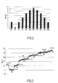
- the figure 2 thus presents the steps followed in an embodiment in which after initial drying is carried out a humidification phase followed by a drying phase.
- the relative humidity RH (controlled by the means 22 for regulating the relative humidity level in the chamber 12) does not vary continuously, but is modified in steps (S0 to S10).
- the weight measurements are carried out continuously; however, measures considered representative of the state of the sample at a given relative humidity level (weight measurement and acquisition of sample information) are those that are performed when the sample reaches the sample. water balance with the surrounding atmosphere.
- a sample 48 is placed in the chamber 12. This sample (generally different from that used to determine W 0 ) has a water content W 0 which corresponds to the relative humidity in the laboratory. 'trial.
- the mass M 0 of this sample is then measured.
- the enclosure is closed, and the relative humidity is brought into it at a rate equal to that prevailing in the test laboratory.
- the sample 48 is placed at a relative humidity level equal to that prevailing in the room in which the test takes place.
- This arrangement makes it possible to reduce the physical disturbance experienced by the sample at the beginning of the test, and thus to increase the representativity of the results obtained.
- it makes it possible to use a precise value for the dry mass of the sample placed in the chamber, which is deduced immediately from the initial mass measurement M 0 , the water content W 0 being known.
- the dry mass of the sample can also be measured by performing a complete drying of the sample placed in the chamber.
- the figure 2 presents the succession of the different levels observed.
- Step S0 corresponds to the initial step indicated above, during which the relative humidity level in the chamber is brought to the same value as in the test laboratory in which the device 10 is located.
- Step S1 corresponds to a drying step, during which the relative humidity level is lowered to about 5%.
- the means 22 for regulating the relative humidity rate impose five levels S2-S6 humidification, during which the relative humidity RH varies from 5% to about 100%, followed by four stages of drying S7- S10, in which the relative humidity RH is reduced to the relative humidity applied at the beginning of the test and equal to that prevailing in the test laboratory, ie in the case presented, 30%.
- a substantially constant temperature is kept close to the sample, of the order of 10 ° C. to 20 ° C., and the pressure is varied, which causes a change in relative humidity.
- the duration of the bearings is sufficient to allow stabilization of the mass of the sample (at each level). Indeed, when the sample reaches the water balance, its mass and therefore its water content W stabilize, depending on the relative humidity in the chamber.
- the duration of the bearings must generally be adapted according to the behavior of the sample.
- the duration of the steps is approximately one hour.
- the figure 3 presents the variations of the water content W, as measured (from the weighings), as a function of time.
- the time axis is represented on the abscissa and only the steps S0 to S6 are represented.
- the indication '1H' corresponds to a test duration of 1 hour.
- On the ordinate is represented the water content W, which is calculated in known manner from the change in weight of the sample, as measured by the weighing apparatus 14.
- the variations of the volume, that is to say the swelling or shrinkage, of the sample are determined.
- FIGS 7A and 7B schematically present two images obtained successively with the aid of the electron microscope 16, in two different stages.
- the images of the microscope are subjected to image analysis by means of specialized software. This allows, by defining the outline of the aggregates, to determine the area and the perimeter of the aggregates.
- the area occupied by the sample occupies an area S1 of the image. From this, we determine the area (also denoted S1) occupied by the aggregate on the sample tray.
- each of the aggregates was inflated with water. It follows for the aggregate considered an increase of the surface S2 that it occupies on the sample holder as its volume.
- the volume deformation can then be calculated:
Landscapes
- Physics & Mathematics (AREA)
- Health & Medical Sciences (AREA)
- Life Sciences & Earth Sciences (AREA)
- Chemical & Material Sciences (AREA)
- Analytical Chemistry (AREA)
- Biochemistry (AREA)
- General Health & Medical Sciences (AREA)
- General Physics & Mathematics (AREA)
- Immunology (AREA)
- Pathology (AREA)
- Analysing Materials By The Use Of Radiation (AREA)
Applications Claiming Priority (1)
| Application Number | Priority Date | Filing Date | Title |
|---|---|---|---|
| FR1054771A FR2961596B1 (fr) | 2010-06-16 | 2010-06-16 | Dispositif et procede de caracterisation d'un materiau |
Publications (1)
| Publication Number | Publication Date |
|---|---|
| EP2397835A1 true EP2397835A1 (de) | 2011-12-21 |
Family
ID=43530250
Family Applications (1)
| Application Number | Title | Priority Date | Filing Date |
|---|---|---|---|
| EP11169714A Withdrawn EP2397835A1 (de) | 2010-06-16 | 2011-06-14 | Vorrichtung und Verfahren zur Charakterisierung eines Materials |
Country Status (2)
| Country | Link |
|---|---|
| EP (1) | EP2397835A1 (de) |
| FR (1) | FR2961596B1 (de) |
Cited By (1)
| Publication number | Priority date | Publication date | Assignee | Title |
|---|---|---|---|---|
| CN115753488A (zh) * | 2022-11-10 | 2023-03-07 | 福州大学 | 基于点云强度的沙滩表层含水率反演方法 |
Citations (1)
| Publication number | Priority date | Publication date | Assignee | Title |
|---|---|---|---|---|
| EP0344465A2 (de) * | 1988-05-10 | 1989-12-06 | Mitsubishi Jukogyo Kabushiki Kaisha | Feuchtigkeitsmesssystem |
-
2010
- 2010-06-16 FR FR1054771A patent/FR2961596B1/fr not_active Expired - Fee Related
-
2011
- 2011-06-14 EP EP11169714A patent/EP2397835A1/de not_active Withdrawn
Patent Citations (1)
| Publication number | Priority date | Publication date | Assignee | Title |
|---|---|---|---|---|
| EP0344465A2 (de) * | 1988-05-10 | 1989-12-06 | Mitsubishi Jukogyo Kabushiki Kaisha | Feuchtigkeitsmesssystem |
Non-Patent Citations (5)
| Title |
|---|
| "COMPUTERIZED THERMOGRAVIMETRIC REACTOR WITH VIDEO MICROSCOPY IMAGING SYSTEM FOR COAL PYROLYSIS AND COMBUSTION STUDIES", REVIEW OF SCIENTIFIC INSTRUMENTS, AIP, MELVILLE, NY, US, vol. 64, no. 6, 1 June 1993 (1993-06-01), pages 1541 - 1548, XP000380689, ISSN: 0034-6748, DOI: 10.1063/1.1144024 * |
| HIRANUMA ET AL: "Using environmental scanning electron microscopy to determine the hygroscopic properties of agricultural aerosols", ATMOSPHERIC ENVIRONMENT, PERGAMON, GB, vol. 42, no. 9, 14 January 2008 (2008-01-14), pages 1983 - 1994, XP022494095, ISSN: 1352-2310, DOI: 10.1016/J.ATMOSENV.2007.12.003 * |
| IERVOLINO E ET AL: "Thermogravimetric device with integrated thermal actuators", MICRO ELECTRO MECHANICAL SYSTEMS (MEMS), 2010 IEEE 23RD INTERNATIONAL CONFERENCE ON, IEEE, PISCATAWAY, NJ, USA, 24 January 2010 (2010-01-24), pages 683 - 686, XP031655036, ISBN: 978-1-4244-5761-8 * |
| LEE JUNGCHUL ET AL: "Microthermogravimetry using a microcantilever hot plate with integrated temperature-compensated piezoresistive strain sensors", REVIEW OF SCIENTIFIC INSTRUMENTS, AIP, MELVILLE, NY, US, vol. 79, no. 5, 6 May 2008 (2008-05-06), pages 54901 - 54901, XP012115405, ISSN: 0034-6748, DOI: 10.1063/1.2913337 * |
| SORGI ET AL: "Analyse microstructurale au MEB environnemental d'une craie soumise a chargement hydrique et mecanique", COMPTES RENDUS - GEOSCIENCE, ELSEVIER, PARIS, FR, vol. 339, no. 7, 6 August 2007 (2007-08-06), pages 468 - 481, XP022183977, ISSN: 1631-0713, DOI: 10.1016/J.CRTE.2007.06.003 * |
Cited By (1)
| Publication number | Priority date | Publication date | Assignee | Title |
|---|---|---|---|---|
| CN115753488A (zh) * | 2022-11-10 | 2023-03-07 | 福州大学 | 基于点云强度的沙滩表层含水率反演方法 |
Also Published As
| Publication number | Publication date |
|---|---|
| FR2961596A1 (fr) | 2011-12-23 |
| FR2961596B1 (fr) | 2014-06-27 |
Similar Documents
| Publication | Publication Date | Title |
|---|---|---|
| Gieseler et al. | Evaluation of tunable diode laser absorption spectroscopy for in‐process water vapor mass flux measurements during freeze drying | |
| Ma et al. | Characterization of pharmaceutical powder blends by NIR chemical imaging | |
| US5487702A (en) | Grain weighing and measuring system | |
| Li et al. | Use of optical coherence tomography and light microscopy for characterisation of mechanical properties and cellular level responses of ‘Centurion’blueberries during weight loss | |
| Lever et al. | The mechanics of snow friction as revealed by micro-scale interface observations | |
| EP0961924A1 (de) | Verfahren und vorrichtung zur bestimmung der stabilität einer emulsion von kohlenwasserstoffen und wasser | |
| FR3078776A1 (fr) | Procédé de Mesure de Pression sans étalonnage dans des dispositifs de jauge à vide micro-fabriqués | |
| Vollrath et al. | Evaluation of heat flux measurement as a new process analytical technology monitoring tool in freeze drying | |
| FR2823307A1 (fr) | Procede et micropresse pour caracteriser les proprietes mecaniques des solides pharmaceutiques | |
| EP2397835A1 (de) | Vorrichtung und Verfahren zur Charakterisierung eines Materials | |
| EP2729796B1 (de) | Messvorrichtung zur gekoppelten messung von wasserwerten von böden | |
| CN101021488A (zh) | 稻谷损伤的检测方法和装置 | |
| FR2667400A1 (fr) | Methode de detection des changements d'etat d'un milieu liquide ou gelifie et dispositif capteur pour la mise en óoeuvre de cette methode. | |
| FR2657434A1 (fr) | Dispositif pour determiner automatiquement des caracteristiques physiques d'un produit et procede de mesure mis en óoeuvre au moyen de ce dispositif. | |
| EP0932036B1 (de) | Permeameter mit grossem Messbereich | |
| WO1995030118A1 (fr) | Procede et dispositif de controle de la lyophilisation sous vide | |
| FR2775076A1 (fr) | Procede et dispositif de controle de la teneur en eau de produits stockes dans une enceinte | |
| Cerri et al. | Sugar cane yield monitor | |
| EP0577512A1 (de) | Verfahren und Vorrichtung zur Bestimmung der Ermüdungsgrenze eines Werkstoffes | |
| CN106290370B (zh) | 流体中凝聚态结构演变实时监测的微距微观图像识别方法 | |
| WO2021229176A1 (fr) | Dispositif de mesure de proprietes physico-chimiques d'une matrice deformable, procede de mise en oeuvre et utilisations | |
| Zeng et al. | A novel infrared thermography-based method for measuring suction at evaporating soil surfaces | |
| CN114166633A (zh) | 基于piv技术快速准确获得土体抗拉强度的试验方法 | |
| EP1989541B1 (de) | Verfahren zur Messung der rheologischen Qualitäten von fermentiertem oder ungesäuertem Teig auf Mehlbasis, sowie Vorrichtung dafür | |
| Enzmann et al. | 3-D imaging and quantification of graupel porosity by synchrotron-based micro-tomography |
Legal Events
| Date | Code | Title | Description |
|---|---|---|---|
| AK | Designated contracting states |
Kind code of ref document: A1 Designated state(s): AL AT BE BG CH CY CZ DE DK EE ES FI FR GB GR HR HU IE IS IT LI LT LU LV MC MK MT NL NO PL PT RO RS SE SI SK SM TR |
|
| AX | Request for extension of the european patent |
Extension state: BA ME |
|
| PUAI | Public reference made under article 153(3) epc to a published international application that has entered the european phase |
Free format text: ORIGINAL CODE: 0009012 |
|
| 17P | Request for examination filed |
Effective date: 20120619 |
|
| 17Q | First examination report despatched |
Effective date: 20150213 |
|
| STAA | Information on the status of an ep patent application or granted ep patent |
Free format text: STATUS: THE APPLICATION IS DEEMED TO BE WITHDRAWN |
|
| 18D | Application deemed to be withdrawn |
Effective date: 20190103 |