EP2397437B1 - Flaschenöffner zum Abschneiden der Flaschenkapsel - Google Patents
Flaschenöffner zum Abschneiden der Flaschenkapsel Download PDFInfo
- Publication number
- EP2397437B1 EP2397437B1 EP10425206A EP10425206A EP2397437B1 EP 2397437 B1 EP2397437 B1 EP 2397437B1 EP 10425206 A EP10425206 A EP 10425206A EP 10425206 A EP10425206 A EP 10425206A EP 2397437 B1 EP2397437 B1 EP 2397437B1
- Authority
- EP
- European Patent Office
- Prior art keywords
- supporting body
- bottle
- cutting element
- shaft
- plates
- Prior art date
- Legal status (The legal status is an assumption and is not a legal conclusion. Google has not performed a legal analysis and makes no representation as to the accuracy of the status listed.)
- Active
Links
Images



Classifications
-
- B—PERFORMING OPERATIONS; TRANSPORTING
- B67—OPENING, CLOSING OR CLEANING BOTTLES, JARS OR SIMILAR CONTAINERS; LIQUID HANDLING
- B67B—APPLYING CLOSURE MEMBERS TO BOTTLES JARS, OR SIMILAR CONTAINERS; OPENING CLOSED CONTAINERS
- B67B7/00—Hand- or power-operated devices for opening closed containers
- B67B7/02—Hand- or power-operated devices for opening closed containers for removing stoppers
- B67B7/04—Cork-screws
- B67B7/0417—Cork-screws with supporting means for assisting the pulling action
- B67B7/0441—Cork-screws with supporting means for assisting the pulling action whereby the supporting means abut around the whole periphery of the neck of the bottle
-
- B—PERFORMING OPERATIONS; TRANSPORTING
- B67—OPENING, CLOSING OR CLEANING BOTTLES, JARS OR SIMILAR CONTAINERS; LIQUID HANDLING
- B67B—APPLYING CLOSURE MEMBERS TO BOTTLES JARS, OR SIMILAR CONTAINERS; OPENING CLOSED CONTAINERS
- B67B7/00—Hand- or power-operated devices for opening closed containers
- B67B7/02—Hand- or power-operated devices for opening closed containers for removing stoppers
- B67B7/04—Cork-screws
- B67B2007/0458—Means for cutting sealing capsules
Definitions
- the present invention relates to a bottle opening device, particularly for cutting the capsule covering the stopper of a bottle.
- corkscrews also known as cork pullers
- bottle cap openers also known simply as bottle openers
- corkscrews are comprised of a self-tapping screw, called a worm, which is screwed into the stopper and to which is subsequently applied an axial traction force that is sufficient to defeat the friction that keeps the stopper in place, so extracting it.
- the traction force is exerted directly by the user, while in others it is amplified by means of levers cooperating with a rack, and in others it is produced by exploiting the Archimedes screw principle.
- the corkscrew is made of steel or of zinc alloys with, occasionally, some portions made of wood, such as the handle in manual models.
- the bottle cap opener is usually comprised of a metal bar that has an opening or a slot into which the cap is inserted in such a way that one side of the slot rests on top of the cap, acting as a fulcrum, and the other side acts on the edge of the cap, lifting it.
- Bottle cap openers are made in countless shapes and finishes.
- bottle opener is usually used to indicate devices that combine different opening systems, including a bottle cap opener and a corkscrew.
- devices are known that are provided with a threaded portion, acting as a corkscrew, and a widened portion provided with a slot, acting as a bottle cap opener.
- bottle opening device is used herein to indicate a device for opening bottles that is provided both with a corkscrew, and more generically with a threaded portion that is adapted to be screwed into a stopper, and also with a bottle cap opener, and more generally with a slot inside which the cap to be lifted and removed is inserted.
- Bottles in particular bottles made of glass, have a thin capsule made of a flexible material wrapped around the neck to cover the stopper.
- devices for opening bottles are known that are provided with means that are especially designed to perform the cut in the capsule.
- the cutting portions are not suitably covered but on the contrary they are located in portions of the device that come into contact with the user's hand, so exposing the user to the risk of cuts and wounds.
- the cutting portion is incorporated in a fixed and permanent manner to the device, and this is particularly disadvantageous because, if the cutting portion is damaged, the entire device must be discarded.
- the capsule cutting means incorporated in known devices are not capable of adapting easily to different sizes of bottle necks.
- IT 1 161 607 discloses a bottle opening device according to the preamble of claim 1 provided with two facing arms, each provided with a cutting element.
- the aim of the present invention is to solve the aforementioned problems, by overcoming the drawbacks of the cited prior art devices.
- an object of the invention is to provide a bottle opening device that functions as a corkscrew, as a bottle cap opener and also as a capsule cutter.
- a further object of the invention is to provide a bottle opening device that performs a well-defined and precise cut of the capsule.
- Another object of the invention is to provide a bottle opening device that is easy and safe to use.
- Another object of the present invention is to provide a bottle opening device that adapts easily to cutting the capsules on bottle necks of different sizes.
- a still further object of the present invention is to provide a bottle opening device that has reduced encumbrance.
- Another object of the present invention is to provide a bottle opening device that optimally combines, both from the functional point of view and also from the point of view of spatial encumbrance, the corkscrew function with the bottle cap opener function.
- Another object of the present invention is to provide a bottle opening device that is highly reliable, easy to implement and at low cost.
- a bottle opening device particularly for cutting the capsule covering the neck of a bottle, comprising a shaft provided with a threaded portion and, above, with a widened portion that has a hole in it, characterised in that said widened portion comprises two plates which are provided internally with mutually aligned openings for the transversal insertion of a stopper, said plates being mutually spaced apart so as to define a space for accommodating a supporting body that is provided with at least one cutting element.
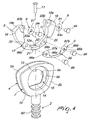
- the bottle opening device indicated generally with the reference numeral 1, comprises a shaft 2 provided with a threaded portion 3 that is adapted to be screwed into the stopper of the bottle.
- the shaft 2 comprises a widened portion 4 that has a hole in it and which comprises two plates 5a and 5b.
- the plates 5a and 5b are provided internally and centrally with openings, respectively 6a and 6b, that are mutually aligned for the transversal insertion of the stopper of a bottle.
- the shaft 2 and the widened portion 4 are made in a single piece.
- the presence of the threaded portion 3 enables the device 1 to act as a corkscrew while the presence of the openings 6a and 6b enables the device 1 to act as a bottle cap opener.
- the plates 5a and 5b can be mutually parallel or mutually inclined internally or externally.
- only one of the two plates 5a and 5b can be inclined while the other remains substantially comprised on the same plane as the shaft 2.
- the plates 5a and 5b have an identical outer profile while the openings 6a and 6b have different profiles from each other.
- the opening 6b has a profile that is substantially circular and the opening 6a has a shape that is substantially defined by a semicircular profile 13 with, at its base, a rectilinear profile 14 that has an inclined thickness.
- the circular opening 6b being larger in size, facilitates the transversal insertion of the stopper while the rectilinear profile 14 of the opening 6a allows its stable fitting onto the circular base of the cap to be lifted.
- the upper area of the circular opening 6b rests on the cap, acting as a fulcrum, while the rectilinear profile 14 of the opening 6a acts on the circular edge of the cap, lifting it.
- the plates 5a and 5b are spaced apart so as to define a space 7 for accommodating a supporting body 8 that supports at least one cutting element 9.
- the plates 5a and 5b can be made as a single body, comprising a connection base 10 that is common to both of the plates and which can be associated with the shaft 2 or which can be integral with the shaft 2.
- the supporting body 8 is fixed to the shaft 2 by means of a first pin 11 which, by passing through a first punching 12a defined on said supporting body 8, is inserted into a first hole 12b that is defined on the base 10 or directly on the shaft 2.
- the device 1 When no cap is inserted between the openings 6a and 6b, the device 1 assumes a rest configuration, in which the cutting element 9 is completely hidden behind the profiles of the opening 6a or also of the opening 6b.
- the device 1 assumes an operational configuration, in which the cutting element 9 protrudes from the profiles of the opening 6a or also of the opening 6b.
- the cutting element 9 in the rest configuration, is covered by the two plates 5a and 5b without entering inside the volume that is defined by the through hole 15 which is defined by the alignment of the two openings 6a and 6b.
- the cutting element 9 In the operational configuration, the cutting element 9 extends into the volume that is defined by the through hole 15 and it comes into contact with the capsule to be cut.
- the supporting body 8 comprises at least one protruding portion 16, which protrudes laterally from the outer lateral profile of the plates 5a and 5b.
- the supporting body comprises two protruding portions 16 that protrude on the two opposite sides of the plates 5a and 5b.
- Each protruding portion 16 is connected with at least one elastically flexible portion 17.
- the device 1 comprises activation means upon which the user acts.
- the activation means are defined by the protruding portions 16.
- the cutting elements 9 associated with the supporting body 8 are pushed towards the centre of the through hole 15 in such a way as to make them protrude inside the plane defined by the opening 6a.
- the cutting elements 9 come into contact with the capsule to be cut.
- the cutting of the capsule covering the stopper is achieved.
- the supporting body 8 can have different shapes and sizes which, however, must be such as to permit the accommodation of the body 8 inside the accommodation space 7 defined between the two plates 5a and 5b.
- the supporting body 8 can have substantially the shape of an arc of circumference in which the protruding portions 16a and 16b are defined respectively at the ends 19a and 19b of the arc.
- the protruding portions 16a and 16b have a greater thickness than that of the remaining portions of the supporting body 8, but their thickness must not exceed the distance between the plates 5a and 5b, i.e. the thickness of the accommodation space 7.
- the elastically flexible portions 17 are defined at the thin and curved branches 20 located at the sides of the central portion 21 of the arc.
- the thin and curved configuration of the branches 20 allow the protruding portions 16 to be bent so as to cause their mutual approach or retreat.
- the cutting element 9 can comprise a disc 91 that is provided with a sharpened edge 92.
- a second pin 94 pass through a second punching 93a defined centrally on the disc 91 and is then inserted into second holes 93b which are defined on the supporting body 8.
- the disc 91 can be fixed to the supporting body 8 so as to permit its rotation about the second pin 94.
- a disc 91 can be associated with each of the ends 19 of the supporting body 8 at the recesses 23 of the protruding portions 16.
- the cutting elements 9 of the device 1 comprise two discs 91, located respectively at the ends 19a and 19b of the supporting body 8.
- the cutting element 9 can comprise an arced arm 95 that is provided at its ends 96a and 96b with sharpened profiles, respectively 97a and 97b.
- Third pins 99 pass through third punchings 98a, positioned at the ends 96a and 96b, and are then inserted into third holes 98b which are defined in the central portion 21 of the supporting body 8.
- the cutting elements 9 of the device 1 comprise in addition to the two discs 91, located respectively at the ends 19a and 19b of the supporting body 8, also an arced arm 95 which is associated with the central portion 21 of the supporting body 8.
- the device 1 can comprise a system, known per se, to facilitate the extraction of the stopper from the bottle.
- a system known per se, to facilitate the extraction of the stopper from the bottle.
- such system comprises a shaft 2 provided with a rack 60 which cooperates with a pair of levers 61 a and 61b which are mounted laterally on a supporting structure 63, which is provided with a perforated cylinder inside which the shaft 2 is inserted.
- the user by acting on the widened portion 4, makes the shaft 2 rotate inside the supporting structure 63 thereby screwing the threaded portion 3 into the stopper and, at the same time, causing the rotation of the levers 61a and 61b upwards and outwards. Subsequently, by pushing the levers 61 a and 61b downwards a force is applied that allows the extraction of the stopper.
- the shaft 2 and the widened portion 4 are made for example of chrome zinc alloy.
- the supporting body 8 is made for example of plastics.
- the cutting elements are made for example of tempered steel.
- the first pins 11, the second pins 94 and the third pins 99 are made for example of steel.
- the device according to the invention fully achieves the aim and objects in that the bottle opening device makes it possible to perform the cut in the capsule that covers the stopper easily, quickly, practically and safely.
- the fact that the cutting element is covered by the plates when in the rest configuration prevents any contact, even accidental, between said cutting element and the user.
- this feature makes it possible to add the capsule cutting functionality to the device without having to excessively modify the aesthetics and encumbrance of the device itself.
- the fact that the cutting element protrudes into the openings only when the device is in the operational configuration increases the level of safety of the device, since to activate such configuration the user must press on the protruding portions with his/her fingers, thus making contact between the cutting element and other parts of the body highly unlikely.
- the fact that pressing on the protruding portions of the supporting body brings the cutting element into contact with the capsule to be cut offers greater ease of adaptation to bottle necks of different diameters.
- increasing or decreasing the pressure on the protruding portions causes the approach of the cutting element towards the neck of the bottle or its retreat therefrom.
- the fact that the cutting element is associated with the supporting body allows the substitution of said supporting body and, in particular, it allows the substitution of the cutting element. This is particularly advantageous if the cutting profile is worn with use.
- a plurality of cutting elements such as, for example, two discs and an arced arm make it possible to achieve a cut that is better defined and of better quality, as well as speeding up the entire cutting operation.
- the device according to the invention has been conceived specifically for bottle opening devices that have both a corkscrew function and also a bottle cap opener function, it can in any case be used, more generally, for devices that act only as corkscrews or only as bottle cap openers.
- the materials employed, as well as the dimensions, may be any according to requirements and to the state of the art.
Landscapes
- Engineering & Computer Science (AREA)
- Mechanical Engineering (AREA)
- Devices For Opening Bottles Or Cans (AREA)
Claims (14)
- Ein Flaschenöffner (1), insbesondere zum Abschneiden der Kapsel, die den Flaschenhals bedeckt, umfassend einen Schaft (2), der mit einem Gewindeabschnitt (3) und darüber mit einem verbreiterten Abschnitt (4) versehen ist, der ein Loch darin hat, dadurch gekennzeichnet, dass der verbreiterte Abschnitt (4) zwei Platten (5a, 5b) umfasst, die innen mit miteinander ausgerichteten Öffnungen (6a, 6b) für das transversale Einführen eines Stopfens versehen sind, wobei die Platten (5a, 5b) voneinander beabstandet sind, um einen Raum (7) zur Aufnahme eines tragenden Körpers (8) zu bestimmen, der mit mindestens einem Schneidelement (9) ausgestattet ist.
- Die Vorrichtung gemäß Anspruch 1, dadurch gekennzeichnet, dass sie eine Ruheanordnung umfasst, wobei das mindestens eine Schneidelement (9) vollständig hinter dem Profil mindestens einer der Öffnungen (6a, 6b) verborgen ist, und eine Arbeitsanordnung, wobei das mindestens eine Schneidelement (9) aus dem Profil mindestens einer der Öffnungen (6a, 6b) herausragt.
- Die Vorrichtung gemäß Anspruch 2, dadurch gekennzeichnet, dass sie Aktivierungsmittel (16) zum Veranlassen des Übergangs von der Ruheanordnung in die Arbeitsanordnung umfasst.
- Die Vorrichtung gemäß Anspruch 1, dadurch gekennzeichnet, dass der tragende Körper (8) lösbar mit dem Schaft (2) verbunden werden kann, wobei das mindestens eine Schneidelement (9) lösbar mit dem tragenden Körper (8) verknüpft werden kann.
- Die Vorrichtung gemäß Anspruch 1, dadurch gekennzeichnet, dass der tragende Körper mindestens einen Abschnitt (16) umfasst, der außen aus den Platten (5a, 5b) herausragt und mit mindestens einem elastisch biegsamen Abschnitt (17) verbunden ist.
- Die Vorrichtung gemäß Anspruch 1, dadurch gekennzeichnet, dass der tragende Körper (8) im Wesentlichen die Form eines Bogens einer Kreislinie hat.
- Die Vorrichtung gemäß Anspruch 5, dadurch gekennzeichnet, dass die herausragenden Abschnitte (16) an jedem Ende des Bogens bestimmt sind.
- Die Vorrichtung gemäß Anspruch 1, dadurch gekennzeichnet, dass das mindestens eine Schneidelement (9) eine Scheibe (91) mit einer geschärften Kante (92) umfasst, die sich um einen Stift (94) dreht, welcher mit dem tragenden Körper (8) verknüpft werden kann.
- Die Vorrichtung gemäß Anspruch 1, dadurch gekennzeichnet, dass das mindestens eine Schneidelement (9) einen gebogenen Arm umfasst, der an seinen Enden mit geschärften gekrümmten Profilen ausgestattet ist.
- Die Vorrichtung gemäß Anspruch 8, dadurch gekennzeichnet, dass sie zwei der Scheiben (91) umfasst, die mit den Enden (19a, 19b) des tragenden Körpers (8) verknüpft sind.
- Die Vorrichtung gemäß Anspruch 1, dadurch gekennzeichnet, dass sie einen gebogenen Arm (95) umfasst, der mit dem zentralen Abschnitt (21) des tragenden Körpers (8) verknüpft ist.
- Die Vorrichtung gemäß Anspruch 1, dadurch gekennzeichnet, dass der Schaft (2) eine Zahnstange (60) umfasst, die mit einem Paar von Hebeln (61a, 61b) zusammenwirkt, welche seitlich an einer tragenden Struktur (63) für den Schaft (2) montiert sind, wobei der Schaft (2) im Verhältnis zu der Struktur (63) drehbar ist.
- Die Vorrichtung gemäß Anspruch 1, dadurch gekennzeichnet, dass mindestens eine der Öffnungen (6a, 6b) der Platten (5a, 5b) von einem halbkreisförmigen Profil mit einem rechteckigen Profil an seiner Basis bestimmt wird, das ausgebildet ist, um stabil mit der kreisförmigen Basis des anzuhebenden Deckels zusammenzupassen.
- Die Vorrichtung gemäß Anspruch 1, dadurch gekennzeichnet, dass der tragende Körper (8) aus Kunststoff besteht.
Priority Applications (2)
| Application Number | Priority Date | Filing Date | Title |
|---|---|---|---|
| EP10425206A EP2397437B1 (de) | 2010-06-17 | 2010-06-17 | Flaschenöffner zum Abschneiden der Flaschenkapsel |
| US13/154,937 US8646137B2 (en) | 2010-06-17 | 2011-06-07 | Bottle opening device for cutting the capsule covering the neck of the bottle |
Applications Claiming Priority (1)
| Application Number | Priority Date | Filing Date | Title |
|---|---|---|---|
| EP10425206A EP2397437B1 (de) | 2010-06-17 | 2010-06-17 | Flaschenöffner zum Abschneiden der Flaschenkapsel |
Publications (2)
| Publication Number | Publication Date |
|---|---|
| EP2397437A1 EP2397437A1 (de) | 2011-12-21 |
| EP2397437B1 true EP2397437B1 (de) | 2012-11-21 |
Family
ID=43033307
Family Applications (1)
| Application Number | Title | Priority Date | Filing Date |
|---|---|---|---|
| EP10425206A Active EP2397437B1 (de) | 2010-06-17 | 2010-06-17 | Flaschenöffner zum Abschneiden der Flaschenkapsel |
Country Status (2)
| Country | Link |
|---|---|
| US (1) | US8646137B2 (de) |
| EP (1) | EP2397437B1 (de) |
Families Citing this family (8)
| Publication number | Priority date | Publication date | Assignee | Title |
|---|---|---|---|---|
| USD716624S1 (en) * | 2013-05-24 | 2014-11-04 | Alexander Philip Bommer | Bottle opener |
| US9440834B2 (en) * | 2013-11-06 | 2016-09-13 | Lifetime Brands, Inc. | Self-centering and self-gripping corkscrew |
| WO2016172835A1 (zh) * | 2015-04-28 | 2016-11-03 | 尚平 | 一种开瓶器 |
| US20170043989A1 (en) * | 2015-08-12 | 2017-02-16 | Kenneth S. Kwak | Winged corkscrew with one or more secondary utensils |
| DE202016106422U1 (de) | 2016-11-16 | 2016-11-28 | Verallia Spain, S.A. | Flasche mit einer durch einen Korken verschließbaren Mündung mit einer Rille zum Zerschneiden der Kapsel |
| USD1022644S1 (en) * | 2020-01-06 | 2024-04-16 | George Edward Hutchison | Corkscrew bottle opener |
| USD1075451S1 (en) * | 2022-09-28 | 2025-05-20 | Deiss Limited | Wine bottle opener |
| USD1033185S1 (en) * | 2023-12-05 | 2024-07-02 | Ningbo Chuangxin Jump E-Commerce Co., Ltd. | Wine bottle opener |
Family Cites Families (6)
| Publication number | Priority date | Publication date | Assignee | Title |
|---|---|---|---|---|
| US1990289A (en) * | 1934-03-14 | 1935-02-05 | Herman S Krueger | Corkscrew |
| US4399720A (en) * | 1982-05-17 | 1983-08-23 | Towle Manufacturing Company | Cork puller |
| IT1161607B (it) * | 1983-02-09 | 1987-03-18 | Jacques Souhart | Dispositivo per tagliare il fondo di una capsula in un sol pezzo,che copre il collo di una bottiglia |
| KR100252705B1 (ko) * | 1997-02-26 | 2000-04-15 | 김인석 | 포일캇타 겸용 오프너 |
| EP1494957B1 (de) * | 2002-04-12 | 2005-12-21 | Heftitec SA | Korkenzieher mit in den griff einsetzbaren kapselschneider |
| US20080022810A1 (en) * | 2006-07-28 | 2008-01-31 | Panetti David F | Wine bottle opener |
-
2010
- 2010-06-17 EP EP10425206A patent/EP2397437B1/de active Active
-
2011
- 2011-06-07 US US13/154,937 patent/US8646137B2/en active Active
Also Published As
| Publication number | Publication date |
|---|---|
| EP2397437A1 (de) | 2011-12-21 |
| US20110308357A1 (en) | 2011-12-22 |
| US8646137B2 (en) | 2014-02-11 |
Similar Documents
| Publication | Publication Date | Title |
|---|---|---|
| US8646137B2 (en) | Bottle opening device for cutting the capsule covering the neck of the bottle | |
| US4437359A (en) | Wine waiter's corkscrews | |
| US8312633B2 (en) | Electric can opener having removable opener tools | |
| CA2178890C (en) | Portable corkscrew with accessory to shear the caps on the neck of bottles | |
| US20150075012A1 (en) | Outil a main perfectionne | |
| CA2920412A1 (en) | Winged corkscrew with one or more secondary utensils | |
| US9457414B2 (en) | Pliers for cutting workpieces | |
| BR9306068A (pt) | Ferramenta para romper um vácuo em um vaso de boca larga para compotas fechado por uma tampa de rosca | |
| US20170043990A1 (en) | Below The Bead Foil Cutter | |
| US9415987B2 (en) | Container opening device and method of use | |
| EP1336587B1 (de) | Korkenzieher mit zwei Abstützarmen | |
| US20080022810A1 (en) | Wine bottle opener | |
| EP2718222A1 (de) | Korkenentferner für eine flasche mit schäumender flüssigkeit | |
| US2975515A (en) | Can opener | |
| US20200189894A1 (en) | Multi-purpose bottle opener | |
| EP2089307A1 (de) | Korkenzieher für sektflaschen | |
| RU178862U1 (ru) | Универсальный нож | |
| CN202640383U (zh) | 一种新型刀剪 | |
| EP2322467A2 (de) | Flaschenöffner | |
| CN201151656Y (zh) | 弹性一轮两圆切割刀 | |
| CN201151653Y (zh) | 弹性一轮五圆切割刀 | |
| CN2442982Y (zh) | 旋转式安瓶切割器 | |
| CN201148337Y (zh) | 弹性三轮三圆切割刀 | |
| CN201151654Y (zh) | 弹性一轮三圆切割刀 | |
| CN201148338Y (zh) | 弹性两轮一圆切割刀 |
Legal Events
| Date | Code | Title | Description |
|---|---|---|---|
| AK | Designated contracting states |
Kind code of ref document: A1 Designated state(s): AL AT BE BG CH CY CZ DE DK EE ES FI FR GB GR HR HU IE IS IT LI LT LU LV MC MK MT NL NO PL PT RO SE SI SK SM TR |
|
| AX | Request for extension of the european patent |
Extension state: BA ME RS |
|
| PUAI | Public reference made under article 153(3) epc to a published international application that has entered the european phase |
Free format text: ORIGINAL CODE: 0009012 |
|
| 17P | Request for examination filed |
Effective date: 20120320 |
|
| GRAP | Despatch of communication of intention to grant a patent |
Free format text: ORIGINAL CODE: EPIDOSNIGR1 |
|
| GRAS | Grant fee paid |
Free format text: ORIGINAL CODE: EPIDOSNIGR3 |
|
| RAP1 | Party data changed (applicant data changed or rights of an application transferred) |
Owner name: GHIDINI CIPRIANO S.R.L. |
|
| GRAA | (expected) grant |
Free format text: ORIGINAL CODE: 0009210 |
|
| AK | Designated contracting states |
Kind code of ref document: B1 Designated state(s): AL AT BE BG CH CY CZ DE DK EE ES FI FR GB GR HR HU IE IS IT LI LT LU LV MC MK MT NL NO PL PT RO SE SI SK SM TR |
|
| REG | Reference to a national code |
Ref country code: GB Ref legal event code: FG4D |
|
| REG | Reference to a national code |
Ref country code: CH Ref legal event code: EP |
|
| REG | Reference to a national code |
Ref country code: AT Ref legal event code: REF Ref document number: 584974 Country of ref document: AT Kind code of ref document: T Effective date: 20121215 |
|
| REG | Reference to a national code |
Ref country code: IE Ref legal event code: FG4D |
|
| REG | Reference to a national code |
Ref country code: DE Ref legal event code: R096 Ref document number: 602010003733 Country of ref document: DE Effective date: 20130124 |
|
| REG | Reference to a national code |
Ref country code: NL Ref legal event code: VDEP Effective date: 20121121 |
|
| REG | Reference to a national code |
Ref country code: AT Ref legal event code: MK05 Ref document number: 584974 Country of ref document: AT Kind code of ref document: T Effective date: 20121121 |
|
| REG | Reference to a national code |
Ref country code: LT Ref legal event code: MG4D |
|
| PG25 | Lapsed in a contracting state [announced via postgrant information from national office to epo] |
Ref country code: SE Free format text: LAPSE BECAUSE OF FAILURE TO SUBMIT A TRANSLATION OF THE DESCRIPTION OR TO PAY THE FEE WITHIN THE PRESCRIBED TIME-LIMIT Effective date: 20121121 Ref country code: ES Free format text: LAPSE BECAUSE OF FAILURE TO SUBMIT A TRANSLATION OF THE DESCRIPTION OR TO PAY THE FEE WITHIN THE PRESCRIBED TIME-LIMIT Effective date: 20130304 Ref country code: LT Free format text: LAPSE BECAUSE OF FAILURE TO SUBMIT A TRANSLATION OF THE DESCRIPTION OR TO PAY THE FEE WITHIN THE PRESCRIBED TIME-LIMIT Effective date: 20121121 Ref country code: FI Free format text: LAPSE BECAUSE OF FAILURE TO SUBMIT A TRANSLATION OF THE DESCRIPTION OR TO PAY THE FEE WITHIN THE PRESCRIBED TIME-LIMIT Effective date: 20121121 Ref country code: NO Free format text: LAPSE BECAUSE OF FAILURE TO SUBMIT A TRANSLATION OF THE DESCRIPTION OR TO PAY THE FEE WITHIN THE PRESCRIBED TIME-LIMIT Effective date: 20130221 |
|
| PG25 | Lapsed in a contracting state [announced via postgrant information from national office to epo] |
Ref country code: LV Free format text: LAPSE BECAUSE OF FAILURE TO SUBMIT A TRANSLATION OF THE DESCRIPTION OR TO PAY THE FEE WITHIN THE PRESCRIBED TIME-LIMIT Effective date: 20121121 Ref country code: PT Free format text: LAPSE BECAUSE OF FAILURE TO SUBMIT A TRANSLATION OF THE DESCRIPTION OR TO PAY THE FEE WITHIN THE PRESCRIBED TIME-LIMIT Effective date: 20130321 Ref country code: BE Free format text: LAPSE BECAUSE OF FAILURE TO SUBMIT A TRANSLATION OF THE DESCRIPTION OR TO PAY THE FEE WITHIN THE PRESCRIBED TIME-LIMIT Effective date: 20121121 Ref country code: GR Free format text: LAPSE BECAUSE OF FAILURE TO SUBMIT A TRANSLATION OF THE DESCRIPTION OR TO PAY THE FEE WITHIN THE PRESCRIBED TIME-LIMIT Effective date: 20130222 Ref country code: PL Free format text: LAPSE BECAUSE OF FAILURE TO SUBMIT A TRANSLATION OF THE DESCRIPTION OR TO PAY THE FEE WITHIN THE PRESCRIBED TIME-LIMIT Effective date: 20121121 Ref country code: SI Free format text: LAPSE BECAUSE OF FAILURE TO SUBMIT A TRANSLATION OF THE DESCRIPTION OR TO PAY THE FEE WITHIN THE PRESCRIBED TIME-LIMIT Effective date: 20121121 |
|
| PG25 | Lapsed in a contracting state [announced via postgrant information from national office to epo] |
Ref country code: AT Free format text: LAPSE BECAUSE OF FAILURE TO SUBMIT A TRANSLATION OF THE DESCRIPTION OR TO PAY THE FEE WITHIN THE PRESCRIBED TIME-LIMIT Effective date: 20121121 |
|
| PG25 | Lapsed in a contracting state [announced via postgrant information from national office to epo] |
Ref country code: CZ Free format text: LAPSE BECAUSE OF FAILURE TO SUBMIT A TRANSLATION OF THE DESCRIPTION OR TO PAY THE FEE WITHIN THE PRESCRIBED TIME-LIMIT Effective date: 20121121 Ref country code: EE Free format text: LAPSE BECAUSE OF FAILURE TO SUBMIT A TRANSLATION OF THE DESCRIPTION OR TO PAY THE FEE WITHIN THE PRESCRIBED TIME-LIMIT Effective date: 20121121 Ref country code: SK Free format text: LAPSE BECAUSE OF FAILURE TO SUBMIT A TRANSLATION OF THE DESCRIPTION OR TO PAY THE FEE WITHIN THE PRESCRIBED TIME-LIMIT Effective date: 20121121 Ref country code: DK Free format text: LAPSE BECAUSE OF FAILURE TO SUBMIT A TRANSLATION OF THE DESCRIPTION OR TO PAY THE FEE WITHIN THE PRESCRIBED TIME-LIMIT Effective date: 20121121 Ref country code: BG Free format text: LAPSE BECAUSE OF FAILURE TO SUBMIT A TRANSLATION OF THE DESCRIPTION OR TO PAY THE FEE WITHIN THE PRESCRIBED TIME-LIMIT Effective date: 20130221 |
|
| PG25 | Lapsed in a contracting state [announced via postgrant information from national office to epo] |
Ref country code: RO Free format text: LAPSE BECAUSE OF FAILURE TO SUBMIT A TRANSLATION OF THE DESCRIPTION OR TO PAY THE FEE WITHIN THE PRESCRIBED TIME-LIMIT Effective date: 20121121 Ref country code: NL Free format text: LAPSE BECAUSE OF FAILURE TO SUBMIT A TRANSLATION OF THE DESCRIPTION OR TO PAY THE FEE WITHIN THE PRESCRIBED TIME-LIMIT Effective date: 20121121 |
|
| PLBE | No opposition filed within time limit |
Free format text: ORIGINAL CODE: 0009261 |
|
| STAA | Information on the status of an ep patent application or granted ep patent |
Free format text: STATUS: NO OPPOSITION FILED WITHIN TIME LIMIT |
|
| 26N | No opposition filed |
Effective date: 20130822 |
|
| REG | Reference to a national code |
Ref country code: DE Ref legal event code: R097 Ref document number: 602010003733 Country of ref document: DE Effective date: 20130822 |
|
| PG25 | Lapsed in a contracting state [announced via postgrant information from national office to epo] |
Ref country code: MC Free format text: LAPSE BECAUSE OF FAILURE TO SUBMIT A TRANSLATION OF THE DESCRIPTION OR TO PAY THE FEE WITHIN THE PRESCRIBED TIME-LIMIT Effective date: 20121121 Ref country code: HR Free format text: LAPSE BECAUSE OF FAILURE TO SUBMIT A TRANSLATION OF THE DESCRIPTION OR TO PAY THE FEE WITHIN THE PRESCRIBED TIME-LIMIT Effective date: 20130731 |
|
| REG | Reference to a national code |
Ref country code: IE Ref legal event code: MM4A |
|
| REG | Reference to a national code |
Ref country code: DE Ref legal event code: R119 Ref document number: 602010003733 Country of ref document: DE Effective date: 20140101 |
|
| REG | Reference to a national code |
Ref country code: FR Ref legal event code: ST Effective date: 20140228 |
|
| PG25 | Lapsed in a contracting state [announced via postgrant information from national office to epo] |
Ref country code: IE Free format text: LAPSE BECAUSE OF NON-PAYMENT OF DUE FEES Effective date: 20130617 Ref country code: DE Free format text: LAPSE BECAUSE OF NON-PAYMENT OF DUE FEES Effective date: 20140101 |
|
| PG25 | Lapsed in a contracting state [announced via postgrant information from national office to epo] |
Ref country code: FR Free format text: LAPSE BECAUSE OF NON-PAYMENT OF DUE FEES Effective date: 20130701 |
|
| REG | Reference to a national code |
Ref country code: CH Ref legal event code: PL |
|
| GBPC | Gb: european patent ceased through non-payment of renewal fee |
Effective date: 20140617 |
|
| PG25 | Lapsed in a contracting state [announced via postgrant information from national office to epo] |
Ref country code: MT Free format text: LAPSE BECAUSE OF FAILURE TO SUBMIT A TRANSLATION OF THE DESCRIPTION OR TO PAY THE FEE WITHIN THE PRESCRIBED TIME-LIMIT Effective date: 20121121 |
|
| PG25 | Lapsed in a contracting state [announced via postgrant information from national office to epo] |
Ref country code: CH Free format text: LAPSE BECAUSE OF NON-PAYMENT OF DUE FEES Effective date: 20140630 Ref country code: LI Free format text: LAPSE BECAUSE OF NON-PAYMENT OF DUE FEES Effective date: 20140630 |
|
| PG25 | Lapsed in a contracting state [announced via postgrant information from national office to epo] |
Ref country code: GB Free format text: LAPSE BECAUSE OF NON-PAYMENT OF DUE FEES Effective date: 20140617 Ref country code: SM Free format text: LAPSE BECAUSE OF FAILURE TO SUBMIT A TRANSLATION OF THE DESCRIPTION OR TO PAY THE FEE WITHIN THE PRESCRIBED TIME-LIMIT Effective date: 20121121 |
|
| PG25 | Lapsed in a contracting state [announced via postgrant information from national office to epo] |
Ref country code: CY Free format text: LAPSE BECAUSE OF FAILURE TO SUBMIT A TRANSLATION OF THE DESCRIPTION OR TO PAY THE FEE WITHIN THE PRESCRIBED TIME-LIMIT Effective date: 20121121 Ref country code: TR Free format text: LAPSE BECAUSE OF FAILURE TO SUBMIT A TRANSLATION OF THE DESCRIPTION OR TO PAY THE FEE WITHIN THE PRESCRIBED TIME-LIMIT Effective date: 20121121 |
|
| PG25 | Lapsed in a contracting state [announced via postgrant information from national office to epo] |
Ref country code: MK Free format text: LAPSE BECAUSE OF FAILURE TO SUBMIT A TRANSLATION OF THE DESCRIPTION OR TO PAY THE FEE WITHIN THE PRESCRIBED TIME-LIMIT Effective date: 20121121 Ref country code: HU Free format text: LAPSE BECAUSE OF FAILURE TO SUBMIT A TRANSLATION OF THE DESCRIPTION OR TO PAY THE FEE WITHIN THE PRESCRIBED TIME-LIMIT; INVALID AB INITIO Effective date: 20100617 Ref country code: LU Free format text: LAPSE BECAUSE OF NON-PAYMENT OF DUE FEES Effective date: 20130617 |
|
| PG25 | Lapsed in a contracting state [announced via postgrant information from national office to epo] |
Ref country code: IS Free format text: LAPSE BECAUSE OF FAILURE TO SUBMIT A TRANSLATION OF THE DESCRIPTION OR TO PAY THE FEE WITHIN THE PRESCRIBED TIME-LIMIT Effective date: 20121121 |
|
| PG25 | Lapsed in a contracting state [announced via postgrant information from national office to epo] |
Ref country code: AL Free format text: LAPSE BECAUSE OF FAILURE TO SUBMIT A TRANSLATION OF THE DESCRIPTION OR TO PAY THE FEE WITHIN THE PRESCRIBED TIME-LIMIT Effective date: 20121121 |
|
| PGFP | Annual fee paid to national office [announced via postgrant information from national office to epo] |
Ref country code: IT Payment date: 20260407 Year of fee payment: 17 |